US4642786A - Method and apparatus for position and orientation measurement using a magnetic field and retransmission - Google Patents
Method and apparatus for position and orientation measurement using a magnetic field and retransmissionDownload PDFInfo
- Publication number
- US4642786A US4642786AUS06/614,250US61425084AUS4642786AUS 4642786 AUS4642786 AUS 4642786AUS 61425084 AUS61425084 AUS 61425084AUS 4642786 AUS4642786 AUS 4642786A
- Authority
- US
- United States
- Prior art keywords
- retransmitter
- receiver
- magnetic field
- transmitter
- orientation
- Prior art date
- Legal status (The legal status is an assumption and is not a legal conclusion. Google has not performed a legal analysis and makes no representation as to the accuracy of the status listed.)
- Expired - Fee Related
Links
- 238000005259measurementMethods0.000titleclaimsabstractdescription25
- 238000000034methodMethods0.000titleclaimsabstractdescription19
- 230000005540biological transmissionEffects0.000abstractdescription5
- 238000004422calculation algorithmMethods0.000description18
- 230000005284excitationEffects0.000description17
- 239000003990capacitorSubstances0.000description9
- 230000008878couplingEffects0.000description7
- 238000010168coupling processMethods0.000description7
- 238000005859coupling reactionMethods0.000description7
- 230000035699permeabilityEffects0.000description6
- 238000004364calculation methodMethods0.000description5
- 238000013461designMethods0.000description4
- 239000003550markerSubstances0.000description4
- 238000001514detection methodMethods0.000description3
- 229910000859α-FeInorganic materials0.000description3
- 230000002238attenuated effectEffects0.000description2
- 238000012937correctionMethods0.000description2
- 230000005670electromagnetic radiationEffects0.000description2
- 239000011159matrix materialSubstances0.000description2
- 230000004048modificationEffects0.000description2
- 238000012986modificationMethods0.000description2
- 238000012544monitoring processMethods0.000description2
- 230000004044responseEffects0.000description2
- 230000009466transformationEffects0.000description2
- 235000011960Brassica ruvoNutrition0.000description1
- 101100386054Saccharomyces cerevisiae (strain ATCC 204508 / S288c) CYS3 geneProteins0.000description1
- 230000009471actionEffects0.000description1
- 230000004075alterationEffects0.000description1
- 230000008859changeEffects0.000description1
- 238000012512characterization methodMethods0.000description1
- 238000004891communicationMethods0.000description1
- 230000007812deficiencyEffects0.000description1
- 230000001419dependent effectEffects0.000description1
- 238000009795derivationMethods0.000description1
- 230000008846dynamic interplayEffects0.000description1
- 238000013507mappingMethods0.000description1
- 239000000463materialSubstances0.000description1
- 230000008707rearrangementEffects0.000description1
- 238000000926separation methodMethods0.000description1
- 239000002356single layerSubstances0.000description1
- 101150035983str1 geneProteins0.000description1
- 230000002123temporal effectEffects0.000description1
- 238000012360testing methodMethods0.000description1
Images


Classifications
- G—PHYSICS
- G01—MEASURING; TESTING
- G01B—MEASURING LENGTH, THICKNESS OR SIMILAR LINEAR DIMENSIONS; MEASURING ANGLES; MEASURING AREAS; MEASURING IRREGULARITIES OF SURFACES OR CONTOURS
- G01B7/00—Measuring arrangements characterised by the use of electric or magnetic techniques
- G01B7/004—Measuring arrangements characterised by the use of electric or magnetic techniques for measuring coordinates of points
- G—PHYSICS
- G01—MEASURING; TESTING
- G01V—GEOPHYSICS; GRAVITATIONAL MEASUREMENTS; DETECTING MASSES OR OBJECTS; TAGS
- G01V3/00—Electric or magnetic prospecting or detecting; Measuring magnetic field characteristics of the earth, e.g. declination, deviation
- G01V3/08—Electric or magnetic prospecting or detecting; Measuring magnetic field characteristics of the earth, e.g. declination, deviation operating with magnetic or electric fields produced or modified by objects or geological structures or by detecting devices
- G01V3/10—Electric or magnetic prospecting or detecting; Measuring magnetic field characteristics of the earth, e.g. declination, deviation operating with magnetic or electric fields produced or modified by objects or geological structures or by detecting devices using induction coils
- G01V3/104—Electric or magnetic prospecting or detecting; Measuring magnetic field characteristics of the earth, e.g. declination, deviation operating with magnetic or electric fields produced or modified by objects or geological structures or by detecting devices using induction coils using several coupled or uncoupled coils
Definitions
- This inventionrelates to a method and apparatus for position and orientation measurement using a magnetic field and retransmission.
- a position and orientation measuring systemincluding a passive sensor unconnected to the computing portion of the system, with the system being capable of tracking a plurality of objects and including great simplicity.
- this combination of featureshas been found to be lacking as should become clear from the detailed discussion of the prior art known to applicant, as follows:
- U.S. Pat. No. 3,868,565 to Kuipersdiscloses a system which detects the position and orientation of an object in two dimensions (FIGS. 9-10) or three dimensions (FIG. 11).
- the objecthas affixed thereto mutually orthogonal magnetic field sensing coils related to magnetic field generating coils. Signals are induced in the sensing coils dependent upon their position and orientation to thereby determine the object's position and orientation.
- This systemis quite different from the systems disclosed herein in that there is no separation of the source coils and the sensor coils, information transformation between the source and the sensor is necessary, no retransmission of the magnetic field is contemplated, the sensor is not passive, the patented invention may only detect one object at a time and there is no means for compensation for non-orthogonality of coils or for metallic scatters.
- U.S. Pat. No. 4,054,881 to Raabdiscloses three mutually-orthogonal radiating antennas each of which transmits electromagnetic radiation to three mutually orthogonal receiving antennas.
- the receiving antennasmeasure the radiated signals and produce nine parameters which enable calculations of the position and orientation of the receiving antennas with respect to the transmitting antennas.
- This patented inventionis quite different from the inventions disclosed herein for many reasons including: there is no retransmission of the magnetic fields utilized therein, the transmitting and receiving antennas are integrally connected in the system and the sensor is not passive; further, there is no means for compensation for non-orthogonality of coils or for metallic scatters.
- U.S. Pat. No. 4,119,908 to Cosman, et al.discloses a means for locating a pole box buried underground which includes the use of a passive marker including a circuit resonant at a particular frequency. A transmitter is utilized to generate the particular frequency of resonance of the passive marker to thereby enable detection thereof.
- the passive marker's resonant circuitmerely changes the magnetic pattern transmitted from the transmitter along the pipe and as such no real retransmission in the sense with which retransmission is contemplated in the present invention is used and, further, any measurements contemplated by the patented invention are only in two dimensions whereas with the present invention three-dimensional, as well as three additional degrees of freedom including pitch, roll, and yaw, are measured.
- U.S. Pat. No. 4,281,321 to Narlow, et al.discloses a system which determines the presence of a surveillance tag attached to merchandise.
- the systemincludes a mat which forms a capacitive coupling with a pedestrian who steps thereon. If this pedestrian is carrying merchandise which includes a surveillance tag attached thereto indicative of the potential theft of the merchandise, the surveillance tag is sensed by the system.
- This inventionis vastly different from the inventions disclosed herein since it merely detects the presence of a surveillance tag and not the precise position and orientation thereof. Further, there is no use in the patented invention of mutually orthogonal coils in either the transmitter or sensor and, further, the system operates with a very high frequency well above the low frequency magnetic near-field utilized by the present invention.
- U.S. Pat. No. 4,303,910 to McCanndiscloses a system for monitoring the position of a retransmitter attached to a target within a work area.
- a transmitter or transmitterstransmit a signal into the work area which is retransmitted back to a receiver.
- the receiverdetermines the position of the retransmitter by interpreting the received signal.
- This inventionis different from the inventions disclosed herein basically because no position or orientation measurements are made and further for the reasons set forth with regard to the above-discussed U.S. Pat. No. 4,281,321.
- U.S. Pat. No. 4,308,530 to Kip, et al.discloses a system which includes a wafer with a resonance circuit including a coil capacitor and diode.
- a transmittertransmits signals at two frequencies and a receiver receives signals retransmitted by the wafer to determine when the wafer is located in an unauthorized location while attached to an object being monitored thereby.
- This systemis a theft-detection system similar in nature to the above-discussed U.S. Pat. No. 4,281,321 and 4,303,910. The system is only able to detect the presence of the receptor-reradiator in a surveillance area and does not detect the position or orientation thereof.
- U.S. Pat. No. 4,356,477 to Vandebultdiscloses a resonant tag circuit responsive to at least one frequency of electromagnetic radiation.
- a transmittertransmits a signal at a frequency at which the circuits in the tag resonate, with the resonant signal being detected by a receiver for a variety of purposes.
- thisis a theft-detection system similar in nature to the above-discussed U.S. Pat. Nos. 4,281,321; 4,303,910 and 4,308,530 and is distinct from the teachings of the present invention for the same reasons as noted hereinabove.
- the present inventionovecomes the deficiencies and shortcomings of the prior art as espoused hereinabove by providing three exemplary embodiments.
- a systemwhich includes three coils deployed as a three-axis antenna and utilized for both transmitting and receiving of magnetic fields between approximately 10 and 100 kilohertz.
- a retransmitteris provided as attached to an object the position and orientation of which are to be determined.
- the transmitterconsists of three passive resonant circuits whose coils are attached together as a three-axis antenna.
- a magnetic fieldis transmitted from the three transmitter/receiver coils sequentially using three different frequencies. These three frequencies correspond to the respective resonant frequencies of the three passive resonant circuits attached to the object.
- Each respective passive resonant circuitretransmits its respective magnetic field and, from these received sequential magnetic fields, the position and orientation of the object may be determined.
- a second embodiment of the present inventionis similar to the above-described first embodiment thereof.
- the main difference therebetweenlies in the fact that the second embodiment uses a separate transmitter for the respective magnetic fields and the coils utilized in the first embodiment as transmitter/receivers, in this embodiment, merely comprise receivers.
- the transmittersequentially transmits the three frequencies which are retransmitted by the retransmitters and received by the receiver coils. From the received magnetic fields, the position and orientation of the object may be determined.
- the systemincludes a transmitter coil, one retransmitter attached to the object the position and orientation of which are to be determined, and nine receiver coils which are deployed as three three-axis antennas.
- the transmitter coiltransmits a magnetic field at a predetermined frequency corresponding to the resonant frequency of the resonance circuit in the retransmitter.
- the magnetic field retransmitted by the retransmitteris received at the three three-axis antennas which convert the field as received thereby into voltages which may be utilized to calculate the position and orientation of the object to which the single retransmitter is attached.
- FIG. 1shows a schematic view of a loop excited with a current to produce a magnetic field including identification of various aspects of the magnetic field for the purpose of the theoretical discussion herein.
- FIG. 2shows the orientation of a transmitter/receiver coil and a retransmitter coil when aligned for maximum received signal.
- FIG. 3shows a schematic view of a first embodiment of the present invention.
- FIG. 4shows a schematic view of a second embodiment of the present invention.
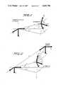
- FIG. 5shows a geometrical view of the three-axis retransmitter with respect to the three-axis transmitter/receiver of FIG. 3 or the three-axis receiver of FIG. 4.
- FIG. 6shows a schematic view of a third embodiment of the present invention.
- FIG. 7shows a geometrical view of the system schematically illustrated in FIG. 6.
- FIG. 8shows a flow chart for the non-linearized algorithm utilized in calculating the estimated position and orientation of an object.
- FIG. 9shows a flow chart for the linearized algorithm which utilizes the estimates from the non-linearized algorithm and calculates the precise position and orientation of the object.
- FIG. 10shows a geometrical view similar to that of FIG. 5, but with a "scatter source" shown.
- a first systemuses a retransmitter having three passive resonant circuits, with resonant frequencies f 1 , f 2 , and f 3 .
- the resonant circuitsare preferably attenuated 30-40 dB at the other resonant circuits' resonant frequencies and at f 0 .
- the transmitter/receiver systemis able to transmit and receive at the frequencies f 0 , f 1 , f 2 , and f 3 .
- the frequency f 0is used to measure the scattering from metallic scatters in the environment.
- the systemtransmits from the x-coil at f 0 and f 1 , the y-coil at f 0 and f 2 , and the z-coil at f 0 and f 3 with pulsed sine waves one after the other.
- the systemreceives the retransmitted field at the three transmitter/receiver coils for each transmitted frequency.
- the systemcould, if desired, used only the x-coil as transmitter for the frequencies f 0 , f 1 , f 2 , and f 3 .
- a second embodiment(FIG. 4) comprises a modification of the embodiment of FIG. 3.
- a separate transmitteris provided and the transmitter/receivers of the FIG. 3 embodiment become merely receivers.
- the single transmittertransmits the three frequencies sequentially for sequential receipt at the three receivers.
- a third embodimentuses a retransmitter, one passive resonant circuit, with resonant frequency f 1 .
- the resonant circuitis attenuated 30-40 dB at f 0 .
- the transmitter/receiver systemis able to transmit and receive at frequencies f 0 and f 1 .
- the frequency f 0is used to measure the scattering from metallic scatters in the environment.
- the systemtransmits pulsed sine waves at frequency f 1 from one coil and receives the retransmitted field at all three three-axis receiver coils.
- the present inventionassumes the use of source and sensor loops whose diameters are small in comparison to the distance separating them. They can therefore be regarded as point sources and point sensors.
- the excitation frequencyis low enough that the field structure retains essentially free-space geometry throughout the region in which the sensor may be located.
- the frequency of the systems described hereinshould be between 10 kHz and 100 kHz for a 1 m motionbox.
- MNIA is the magnetic moment of the loop and A and N represent the area and number of turns of the loop and ⁇ T is the relative permeability of the ferrite inside the coil.
- ⁇ Tis the relative permeability of the ferrite inside the coil.
- the received voltage of the sensor generated from the magnetic field of the source coil, when aligned for maximum received signal as shown in FIG. 2is:
- ⁇ Rthe relative permeability of the ferrite inside the receiver coil
- N RNumber of turns of the receiver loop
- the coilsare arranged in two three-axis antennas; the source and the sensor (See FIG. 5). This means that the first coil (the x-coil) is placed for maximum signal in the x-axis direction the second coil (the y-coil) is placed for maximum signal in the y-axis direction and the third coil (the z-coil) is placed for maximum signal in the z-axis direction.
- the excitation of a three-axis magnetic dipole source and the resultant fields at a particular locationare most conveniently described in vector notation.
- the excitation of the sourceis therefore represented by ##EQU1##
- the coupling between a source and sensor of arbitrary position and orientationcan be determined by inserting orthogonal rotation matrices into (5).
- the geometry for two embodiments of systems in accordance with the present inventionis shown in FIG. 5. These matrices are based upon position azimuth ( ⁇ ), position elevation ( ⁇ ), orientation azimuth ( ⁇ ), orientation elevation ( ⁇ ), and orientation roll ( ⁇ ), as shown in Table 1.
- the output f o from a similarly aligned equivalent sensorthen has the same form as (5), i.e.,
- the output of the zero-orientation sensoris then found by applying inverse position and orientation rotations, thus
- the output of the multi-axis sensor of arbitrary orientation( ⁇ , ⁇ , ⁇ ) is determined by applying orientation azimuth, elevation and roll rotations to the output of the zero-orientation sensor, thus
- equations 1-10were made in order to solve the simple case of a three-axis source and a three-axis sensor.
- the situation nowconsists of a three-axis source which transmits the magnetic field and a retransmitter which receives the magnetic field.
- the retransmitterconsists of three passive resonance circuits, so that when the magnetic field is received, the circuit will be in resonance and the magnetic field will be retransmitted toward the transmitter which also works as a receiver.
- the same method as described aboveis used where the retransmitter is considered as the source and the transmitter/receiver is considered as the sensor.
- a Treceive area of transmitter coil
- M RTrelative permeability of retransmitter coil
- a RTreceive area of retransmitter coil
- N RTnumber of turns in retransmitter coil
- I RTcurrent in retransmitter
- Q RTquality factor of retransmitter coil
- the retransmittertransmits the field ##EQU6##
- the induced voltage in the receiveris ##EQU7##
- ⁇ Rrelative permeability of receiver coil
- N Rnumber of turns in receiver coil
- a Rreceive area of receiver coil
- the voltage placed over the coil in order for it to transmit a magnetic fieldmust be subtracted from the sensed voltage over the coil in order to get the received signal.
- the transmitter coilWhen the transmitter coil generates a magnetic field, voltages are induced over the receiver coils unless the receiver coils and the transmitter coil are perpendicular to each other. The induced voltages are measured initially for all operating frequencies with no retransmitters present. A compensation can then be made using comparators or by preprogramming the microcomputer.
- the final designs of the systems disclosed hereinmust take into account the following stability considerations: (1) temperature stability, (2) double induced voltage, (3) retransmitter influence on the frequency of the transmitter, (4) retransmitter influence on transmitter amplitude, (5) frequency stability of the retransmitter, (6) the errors caused by circular or square loops.
- Step 1The transmitter/receiver, transmits a magnetic field at the frequency f 1 from the x-coil placed for maximum signal in the x-axis direction.
- This magnetic fieldwill be received at the x-axis coil in the retransmitter, placed for maximum received signal in the x-axis direction (f 1 is the resonance frequency for this resonant circuit; but it is not the resonance frequency for the circuitry which includes the y-axis coil or the z-axis coil).
- f 1is the resonance frequency for this resonant circuit; but it is not the resonance frequency for the circuitry which includes the y-axis coil or the z-axis coil).
- Step 2The transmitter/receiver transmits a magnetic field at the frequency f 2 from the y-coil placed for maximum signal in the y-axis direction. This magnetic field will be received at the y-coil in the retransmitter, placed for maximum received signals in the y-axis direction. (f 2 is the resonance frequency for this resonant circuit; but is not the resonance frequency for the circuits which include x-axis coil or z-axis coil). Since the retransmitter is in resonance, a magnetic field will be retransmitted toward the transmitter/receiver. This magnetic field will be received at the three transmitter/receiver coils generating a voltage over each of the coils. This gives the vector equation (21) which contains three equations: ##EQU10##
- Step 3The transmitter/receiver transmits a magnetic field at the frequency f 3 from the coil placed for maximum signal in the z-axis direction.
- This magnetic fieldwill be received at the z-axis coil in the retransmitter, placed for maximum received signal in the z-axis direction (f 3 is the resonance frequency for this resonant circuit; but is not the resonance frequency for the circuits which include x-axis coil or y-axis coil). Since the retransmitter is in resonance, a magnetic field will be retransmitted toward the transmitter/receiver.
- This magnetic fieldwill be received at the three transmitter/receiver coils generating a voltage over each of the coils. This gives the vector equation (22) which contains three equations: ##EQU11##
- the received field at the retransmitteris: ##EQU12##
- the received fields at the receiverare:
- Equations 26, 27 and 28are equations 24 and 25 written out fully.
- Equations 29 and 30reflect the case wherein the transmitter, receiver and retransmitter coordinate systems are aligned.
- the preliminary determination of position quadrantcan be done in a manner known to those skilled in the art.
- orientation determinationit is useful to begin the explanation of orientation determination by developing an algorithm that determines orientation in the special case of the retransmitter located on the positive x-axis in the transmitter/receiver coordinate-system.
- the x-axis responsesare to be synthesized as linear combinations of the real responses which are the outputs of the transmitter/receiver located at an arbitrary location, as follows: ##EQU32##
- the non-linearized algorithmis shown in FIG. 8.
- the equation relating signal amplitude to retransmitter position and orientationcan be linearized with a linearized algorithm in the vicinity of the initial position and orientation estimate calculated as explained hereinabove with the nonlinearized equations.
- the nine linearized equationscan then be solved for the differences between the initial position and orientation estimates and the true position and orientation. Recursive application of this linearized solution overcomes the nonlinearitites inherent in moderate position and orientation errors.
- the initial or previous estimates of position and orientationcan be used to compute a set of amplitudes ( ⁇ 1 .sbsb.x, ⁇ 1 .sbsb.y, ⁇ 1 .sbsb.z, ⁇ 2 .sbsb.x, ⁇ 2 .sbsb.y, ⁇ 2 .sbsb.z, ⁇ 3 .sbsb.x, ⁇ 3 .sbsb.y, ⁇ 3 .sbsb.z), that would be produced if the estimates were correct.
- the difference between the estimated and the true position and orientation parametersare given by ##EQU38## where the elements contain estimated noise for the nine different magnetic fields.
- the noiseincludes atmospheric noise, room noise, retransmitter and receiver noise.
- the linearized algorithmis shown in FIG. 9.
- the transmitter/receiver axesare activated one by one at ⁇ 0 with the retransmitter in place.
- the following nine measurementsare made: ##EQU39##
- Sx, Sy and Szare constants containing the magnitude of the scattered magnetic field of the metallic scatter.
- ⁇ 1 , ⁇ 1 , ⁇ 1 , ⁇ 1 , ⁇ 1 , ⁇ 1 , and ⁇ 1are the coordinates of the metallic scatter seen from the transmitter/receiver.
- the nine equationsare solved for the nine unknowns, ⁇ 1 , ⁇ 1 , ⁇ 1 , ⁇ 1 , ⁇ 1 , ⁇ 1 , S x , S y , S z .
- the systems disclosed hereinuse a new method for calibration as compensation for any nonorthogonalty of coils, namely an automatic scanning routine.
- the calibrationis made in an area where there are no metallic scatters.
- the transmitter/receiver and retransmitterare employed in a fixed gimbal, where the relative position and orientation ( ⁇ 12 , ⁇ 12 , ⁇ 12 , ⁇ 12 , ⁇ 12 , ⁇ 12 , ⁇ 12 ) are known. Instead of turning the coils, the magnetic field is generated in a pattern, which electronically "turns" the transmitter coils.
- Step 1align retransmitter x-coil with transmitter/receiver x-coil.
- the measurementsare made for two different transmitter orientations (electronic scanning) ⁇ 0 and the unknowns ⁇ 01 and ⁇ 01 are found.
- the methodis similar for the next steps.
- Step 2Align retransmitter y-coil with transmitter/receiver x-coil.
- Step 3Align retransmitter z-coil with transmitter/receiver x-coil.
- Step 4Align transmitter/receiver y-coil with retransmitter y-coil.
- Step 5and align transmitter/receiver z-coil with transmitter z-coil.
- This alignment procedurewill not influence the field-pattern calibration because the two measurements used in each step are ⁇ 0 .
- the systemsare also compensated for the possibility of non-ideal dipole, in that a mapping of the field is made in the same area as described above.
- the measurementsare made by electronically "turning" the transmitter coils in steps of 1° in all the planes.
- the mapped measurementsare saved in the computer memory and are used to increase the accuracy of the system.
- the mapped measurementsare used to correct the initial position and orientation estimates similarly to the method used in the linearized algorithm.
- the coil design parametersare N, I, 1 1 , 1 2 , 1 3 , and ⁇ 1 .
- the size of the retransmitter coilsis normally determined by the particular application. The larger the value of ⁇ 1 , the more magnetic field will be transmitted and/or received. Calculations show that ⁇ 1 ⁇ 4, if the retransmitter coils are limited to a cube dimension. By selecting a design where longer ferrite rods are possible, ⁇ 1 >20 can be achieved.
- the size of the retransmittercan be less than a cube of 20 mm 3 with proper design and no limitation on the transmitter/receiver dimensions.
- Position accuracy within 1% of the distance between transmitter/receiver and retransmitter, and orientation accuracy within 0.5°are achieved.
- the system 10includes a transmitter/receiver section 11 and a retransmitter generally designated by the reference numeral 20.
- the transmitter/receiver section 11includes an x-axis transmitter/receiver 13, a y-axis transmitter/receiver 15 and a z-axis transmitter/receiver 17.
- the retransmitter 20is shown in FIG. 3 in a schematic fashion with the three components thereof shown separately; however, it is to be understood that the x, y and z-axis retransmitters of the retransmitter 20 are mounted together in substantially mutually orthogonal relation.
- the retransmitter 20includes an x-axis retransmitter 21, a y-axis retransmitter 25 and a z-axis retransmitter 29.
- the x-axis retransmitterincludes a coil 22 and a capacitor 23.
- Reference numeral 24refers to a resistor which is shown in the circuitry of the retransmitter 21. In reality, there is no resistor in the retransmitter circuitry, however, the resistor 24 is shown as an indication of the inherent resistances in the circuitry of the retransmitter 21 caused by the wiring and other factors as is known to those skilled in the art.
- the retransmitter 25includes a coil 26 and a capacitor 27 with a resistor 28 being shown for the same reasons as discussed above regarding the resistor 24.
- the retransmitter 29includes a coil 30 and a capacitor 31 with the resistor 32, again, being shown for the same reasons as discussed hereinabove with respect to the resistor 24.
- an oscillator 35is connected thereto for the purpose of providing a voltage thereacross at a frequency f 1 .
- a comparator 41is provided so that a comparison can be made of the voltage across the oscillator 35 and the voltage induced across the coil 14 by one of the retransmitters 21, 25 or 29.
- the transmitter/receiver 15has connected thereto an oscillator 37 and a comparator 43 while the transmitter/receiver 17 has connected thereto an oscillator 39 and a comparator 45.
- each comparatorConnected to each comparator is a bandpass filter 47 provided so that only the magnetic field of the transmitted frequency is received and a preamplifier 49 which amplifies the signal coming from the bandpass filter 47.
- the signals being outputted by the preamplifiers 49are inputted into a multiplexer 53 which is controlled by the microprocessor 57.
- the signals inputted to the multiplexer 53 from the preamplifiers 49are outputted therefrom to an analog-to-digital converter 55 which converts the signals to digital signals usable by the microprocessor 57.
- the microprocessor 57also controls the control circuit 51 which controls the operation of the oscillators 35, 37 and 39 so that only one oscillator is operating at any given moment.
- a display 59is connected to the microprocessor to display any data calculated thereby as to the position and orientation of an object (not shown in FIG. 3) to which the retransmitter 20 is attached.
- FIG. 3also shows retransmitter 200, including retransmitters 210, 250, and 290.
- the x-axis retransmitterincludes the coil 220, the capacitor 230, and the inherent resistor 240.
- the y-axis retransmitterincludes the coil 260, the capacitor 270, and the inherent resistor 280.
- the z-axis retransmitterincludes the coil 300, the capacitor 310, and the inherent resistor 320.
- the system 10may be utilized to determine the position and orientation of both the retransmitters 20 and 200, since the retransmitters 21, 25 and 29 of retransmitter 20 are designed to resonate at distinct frequencies f1, f2 and f3 and the retransmitters 210, 250 and 290 of retransmitter 200 are designed to resonate at distinct frequencies f10, f20, and f30.
- the oscillator 35can oscillate at both f1 and f10
- the oscillator 37can oscillate at both f2 and f20
- the oscillator 39can oscillate at both f3 and f30.
- as many retransmitters as desiredmay be simultaneously used.
- the control circuit 51is controlled by the microprocessor 57 to first cause the oscillator 35 to place a voltage across the transmitter/receiver 13 at a predetermined frequency f 1 .
- This frequencyis received by the retransmitter 21, the circuitry of which is designed to retransmit at the frequency f 1 .
- This retransmission of the frequency f 1is sensed at each of the transmitter/receivers 13, 15 and 17.
- the comparator 41subtracts the voltage received at the coil 14 from the voltage outputted on the oscillator 35 and presents this signal to the multiplexer 53 via the bandpass filter 47 and preamplifier 49.
- the comparator 43receives as an input the voltage induced in coil 16 from the retransmitter 21.
- the oscillator 39was not operating, so the signal outputted by the comparator 43 arrived at by subtracting the voltage across the coil 16 from the voltage across the oscillator 37 is, in fact, the full negative value of the voltage across the coil 16.
- No voltageis induced over coil 16 caused by the magnetic field generated by the voltage placed over the coil 14, since the coils 14 and 16 are perpendicular to each other.
- This valueis inputted into the multiplexer 53 via the bandpass filter 47 and the preamplifier 49.
- the coil 18also receives the retransmitted signal from the retransmitter 21 and has a voltage induced thereacross.
- the comparator 45subtracts the induced voltage across the coil 18 from 0 and outputs a signal to the multiplexer 53 via the bandpass filter 47 and the preamplifier 49 equal to the full negative value of the voltage induced across the coil 18 by the retransmitter 21. No voltage is induced over coil 18 caused by the magnetic field generated by the voltage placed over the coil 14 since the coils 14 and 18 are perpendicular to each other.
- the y-axis retransmitter 25retransmits the signal which induces voltages across the three coils 14, 16 and 18.
- the comparator 43Since the oscillator 37 is in operation, the comparator 43 outputs a signal equal to the difference between the voltage across the oscillator 37 less the voltage induced across the coil 16 by the y-axis transmitter 25. Since the oscillators 35 and 39 do not operate during the operation of the oscillator 37, the respective comparators 41 and 45 send signals to the multiplexer 53 equal to the full negative value of the respective voltages induced across the coils 14 and 18. From the above explanation, the explanation with regard to the z-axis circuitry should be clearly evident.
- the multiplexer 53After the three oscillators 35, 37 and 39 have been sequentially actuated, a total of nine voltages have been received by the multiplexer 53, have been converted to digital signals by the analog-to-digital converter 55, and have been inputted to the microprocessor 57. From these nine received voltages, the estimates of the position and orientation of the retransmitter 20 are calculated using the non-linearized algorithm discussed hereinabove and from the data calculated through the use of the non-linearized algorithm, the linearized algorithm also discussed hereinabove is utilized to calculate the actual position of the retransmitter in terms of the coordinates x, y and z and the orientation of the retransmitter 20 in terms of the orientation coordinates ⁇ , ⁇ and ⁇ .
- FIG. 4shows a second embodiment of the system in accordance with the present invention which is slightly modified from the system described in conjunction with FIG. 3.
- like elementswill be referred to with like primed reference numerals.
- the embodiment of FIG. 4will be discussed in terms of its distinctions from the embodiment of FIG. 3.
- the transmitter/receiver structure of FIG. 3has been replaced with a separate transmitter 36 and three receivers 3, 5 and 7.
- the transmitter 36is connected with a single oscillator 34 which is adjustable by the microprocessor 57' to place a voltage across the transmitter 36 which is at one of three predetermined frequencies corresponding to the resonant frequencies of the respective retransmitters 21', 25' and 29'.
- the oscillator 34has three output lines which go to the respective comparator 41', comparator 43' and comparator 45'.
- FIG. 4also shows retransmitter 200', including retransmitters 210', 250' and 290'.
- the system 10'may be utilized to determine the position and orientation of both the retransmitters 20' and 200'. Since the retransmitters 21', 25' and 29' of retransmitter 20' are designed to resonate at frequencies f1, f2 and f3, and the retransmitters 210', 250', and 290' of retransmitter 200' are designed to resonate at frequencies f10, f20 and f30. All frequencies are different from each other. Thus the oscillator 34 can oscillate at all the above mentioned frequencies. In a similar fashion, as many retransmitters as desired may be simultaneously used.
- FIG. 5illustrates the geometry for position and orientation measurement of the embodiment of FIGS. 3 and 4.
- the figureshows, schematically, the retransmitters as well as the transmitter/receiver (FIG. 3) or receiver (FIG. 4).
- the position and orientation parametersare illustrated in FIG. 5.
- FIG. 6illustrates a third exemplary embodiment of the present invention.
- the System 100includes a single retransmitter 121 having a coil 123, a capacitor 125, and with reference numeral 127 referring to a resistance which is shown only as representative of the inherent resistances within the circuitry of the retransmitter 121.
- the System 100further includes three three-axis receivers A, B and C with the receiver A consisting of coils 102, 104 and 106 mounted on respective members 101, 103 and 105 which may, if desired, comprise the same member upon which all three coils 102, 104 and 106 are simultaneously wound.
- the receiver Bconsists of coils 108, 110 and 112 mounted on respective members 107, 109 and 111 which, again, may comprise a single member with the three coils 108, 110 and 112 wound therearound.
- the receiver Cconsists of coils 114, 116 and 118 wound around respective members 113, 115 and 117 which may, again, if desired, consist of the same member with the coils 114, 116 and 118 simultaneously wound therearound.
- Each individual coilhas an output connected to the multiplexer 153 via a respective filter 147 and the preamp 149 which operate in the same manner as the corresponding elements discussed hereinabove with respect to the embodiments of FIGS. 3 and 4.
- the microprocessor 157controls the operation of the multiplexer 153 to thereby control the outputting of individual signals from the multiplexer 153 to the analog-to-digital converter 155 which converts the signals to digital signals usable by the microprocessor 157.
- An oscillator 134is provided which is controlled by the microprocessor 157 and which places a voltage across the transmitter coil 136, which voltage is at a predetermined chosen frequency.
- the transmitter 136includes a housing 119 with a coil 120 wound therearound.
- FIG. 6also shows retransmitter 1210, including coil 1230, the capacitor 1250, and the inherent resistor 1270.
- the system 100may be utilized to determine the position and orientation of both the retransmitters 121 and 1210, since the retransmitter 121 is designed to resonate at the frequency f1 and the retransmitter 1210 is designed to resonate at the frequency f2.
- the oscillator 134can oscillate at both f1 and f2.
- as many retransmitters as desiredmay be simultaneously used.
- the receivers A, B and Care deployed in spaced relation within a work area as best shown in FIG. 7.
- the transmitter 136is also located adjacent the work area and is operated by the microprocessor to transmit a magnetic field at the resonant frequency fo the retransmitter 121.
- the retransmitterresonates and retransmits this frequency toward the nine coils arranged as receivers A, B and C.
- This retransmission of the magnetic fieldcreates nine distinct voltages at the respective nine coils which voltages are related to the position and orientation of the retransmitter 121 within the work area.
- Each voltageis processed to a respective filter 147 and preamp 149 before being inputted in the multiplexer 153.
- the signalsare fed through the analog-to-digital converter 155 and thence are inputted in the form of digital signals into the microprocessor 157.
- the induced voltage, at the coils 102, 104, 106, 108, 110, 112, 114, 116 and 118,is caused by the magnetic field generated by the voltage placed over coil 136. These voltages are measured by an initial calibration at the frequencies f1, f2 and f3 with no retransmitters present.
- the inputted signalsare first compensated therefore in the microprocessor.
- the microprocessorutilizes the non-linearized algorithm and the linearized algorithm discussed hereinabove to calculate an estimate of the position and orientation of the retransmitter 121, and from this data the true position and orientation of the retransmitter 121.
- field distortion calibrations and compensations for metallic scattersmay be undertaken as well as compensations for non-orthogonalities of the three axis receivers A, B and C.
- a further compensation for non-ideal dipole as discussed hereinabovemay be undertaken.
- the systems disclosed hereincan measure the position and orientation of several targets placed on a person's hand.
- the systems in accordance with the present inventioncan be utilized to measure the position and orientation of several targets placed on the human body (gaitanalysis).
- the systems disclosed hereinabove in accordance with the present inventioncan be utilized to measure the position and orientation of a target in a fixed three-dimensional space. These measurements may be made continuously or on a point-by-point basis. Further, the invention may be utilized to make six-dimensional drawings of any model placed in the three-dimensional space.
- the invention disclosed hereinmay be utilized as a six-dimensional input for computer-type games.
- the systems disclosed hereinmay be utilized in stress and vibration monitoring of machines and large structures. They may also be used in deformation tests of polymeric materials and for alignment, angle measurement and board sighting operations.
- the systems disclosed hereinmay be utilized as a direct input device for communication and control devices in view of the passive nature of the target.
- the output device and the displayare active.
- the systems disclosed hereinmay be utilized in conjunction with a non-preprogrammed robot. All that must be done is attach a retransmitting target at the point where action is to be taken by the robot. As such, dynamic interaction is possible between the robot and the object.
- the retransmittermay be as small as 15 mm 3 for a work area of the size 1 m 3 . Similar parameters may be utilized in the retransmitter 121 disclosed in conjunction with the embodiment of FIG. 6.
- the transmitter/receiver coils of the embodiment of FIG. 3, as well as the receiver coils of the embodiments of FIGS. 4 and 6,may be wound on cubes of a size 25 mm 3 . Again, these parameters are merely exemplary and should not be considered to be limiting in any way upon the teachings of the present invention.
Landscapes
- Physics & Mathematics (AREA)
- Engineering & Computer Science (AREA)
- Remote Sensing (AREA)
- Life Sciences & Earth Sciences (AREA)
- General Physics & Mathematics (AREA)
- Electromagnetism (AREA)
- Environmental & Geological Engineering (AREA)
- Geology (AREA)
- General Life Sciences & Earth Sciences (AREA)
- Geophysics (AREA)
- Measurement Of Length, Angles, Or The Like Using Electric Or Magnetic Means (AREA)
Abstract
Description
This invention relates to a method and apparatus for position and orientation measurement using a magnetic field and retransmission. There has long been a need for a position and orientation measuring system including a passive sensor unconnected to the computing portion of the system, with the system being capable of tracking a plurality of objects and including great simplicity. In the prior art, this combination of features has been found to be lacking as should become clear from the detailed discussion of the prior art known to applicant, as follows:
U.S. Pat. No. 3,868,565 to Kuipers discloses a system which detects the position and orientation of an object in two dimensions (FIGS. 9-10) or three dimensions (FIG. 11). For example, (FIG. 11), the object has affixed thereto mutually orthogonal magnetic field sensing coils related to magnetic field generating coils. Signals are induced in the sensing coils dependent upon their position and orientation to thereby determine the object's position and orientation. This system is quite different from the systems disclosed herein in that there is no separation of the source coils and the sensor coils, information transformation between the source and the sensor is necessary, no retransmission of the magnetic field is contemplated, the sensor is not passive, the patented invention may only detect one object at a time and there is no means for compensation for non-orthogonality of coils or for metallic scatters.
U.S. Pat. No. 4,054,881 to Raab discloses three mutually-orthogonal radiating antennas each of which transmits electromagnetic radiation to three mutually orthogonal receiving antennas. The receiving antennas measure the radiated signals and produce nine parameters which enable calculations of the position and orientation of the receiving antennas with respect to the transmitting antennas. This patented invention is quite different from the inventions disclosed herein for many reasons including: there is no retransmission of the magnetic fields utilized therein, the transmitting and receiving antennas are integrally connected in the system and the sensor is not passive; further, there is no means for compensation for non-orthogonality of coils or for metallic scatters.
U.S. Pat. No. 4,119,908 to Cosman, et al., discloses a means for locating a pole box buried underground which includes the use of a passive marker including a circuit resonant at a particular frequency. A transmitter is utilized to generate the particular frequency of resonance of the passive marker to thereby enable detection thereof. There are several differences from this invention and the inventions disclosed herein including the fact that the transmitter is moved while the passive marker remains stationary just opposite to the structure and operation of the present invention, the passive marker's resonant circuit merely changes the magnetic pattern transmitted from the transmitter along the pipe and as such no real retransmission in the sense with which retransmission is contemplated in the present invention is used and, further, any measurements contemplated by the patented invention are only in two dimensions whereas with the present invention three-dimensional, as well as three additional degrees of freedom including pitch, roll, and yaw, are measured.
U.S. Pat. No. 4,281,321 to Narlow, et al., discloses a system which determines the presence of a surveillance tag attached to merchandise. The system includes a mat which forms a capacitive coupling with a pedestrian who steps thereon. If this pedestrian is carrying merchandise which includes a surveillance tag attached thereto indicative of the potential theft of the merchandise, the surveillance tag is sensed by the system. This invention is vastly different from the inventions disclosed herein since it merely detects the presence of a surveillance tag and not the precise position and orientation thereof. Further, there is no use in the patented invention of mutually orthogonal coils in either the transmitter or sensor and, further, the system operates with a very high frequency well above the low frequency magnetic near-field utilized by the present invention.
U.S. Pat. No. 4,303,910 to McCann discloses a system for monitoring the position of a retransmitter attached to a target within a work area. A transmitter or transmitters transmit a signal into the work area which is retransmitted back to a receiver. The receiver determines the position of the retransmitter by interpreting the received signal. This invention is different from the inventions disclosed herein basically because no position or orientation measurements are made and further for the reasons set forth with regard to the above-discussed U.S. Pat. No. 4,281,321.
U.S. Pat. No. 4,308,530 to Kip, et al., discloses a system which includes a wafer with a resonance circuit including a coil capacitor and diode. A transmitter transmits signals at two frequencies and a receiver receives signals retransmitted by the wafer to determine when the wafer is located in an unauthorized location while attached to an object being monitored thereby. This system is a theft-detection system similar in nature to the above-discussed U.S. Pat. No. 4,281,321 and 4,303,910. The system is only able to detect the presence of the receptor-reradiator in a surveillance area and does not detect the position or orientation thereof.
U.S. Pat. No. 4,356,477 to Vandebult discloses a resonant tag circuit responsive to at least one frequency of electromagnetic radiation. A transmitter transmits a signal at a frequency at which the circuits in the tag resonate, with the resonant signal being detected by a receiver for a variety of purposes. Again, this is a theft-detection system similar in nature to the above-discussed U.S. Pat. Nos. 4,281,321; 4,303,910 and 4,308,530 and is distinct from the teachings of the present invention for the same reasons as noted hereinabove.
The following prior art U.S. patents are also known to applicant and are believed to be of only general interest to the teachings of the present invention: Nos. 3,457,502; 3,644,825; 4,041,285; 4,160,204 and 4,314,251.
The present invention ovecomes the deficiencies and shortcomings of the prior art as espoused hereinabove by providing three exemplary embodiments.
In a first embodiment of the present invention, a system is provided which includes three coils deployed as a three-axis antenna and utilized for both transmitting and receiving of magnetic fields between approximately 10 and 100 kilohertz. A retransmitter is provided as attached to an object the position and orientation of which are to be determined. The transmitter consists of three passive resonant circuits whose coils are attached together as a three-axis antenna. In the operation of the system, a magnetic field is transmitted from the three transmitter/receiver coils sequentially using three different frequencies. These three frequencies correspond to the respective resonant frequencies of the three passive resonant circuits attached to the object. Each respective passive resonant circuit retransmits its respective magnetic field and, from these received sequential magnetic fields, the position and orientation of the object may be determined.
A second embodiment of the present invention is similar to the above-described first embodiment thereof. The main difference therebetween lies in the fact that the second embodiment uses a separate transmitter for the respective magnetic fields and the coils utilized in the first embodiment as transmitter/receivers, in this embodiment, merely comprise receivers. The transmitter sequentially transmits the three frequencies which are retransmitted by the retransmitters and received by the receiver coils. From the received magnetic fields, the position and orientation of the object may be determined.
In a third embodiment of the present invention, the system includes a transmitter coil, one retransmitter attached to the object the position and orientation of which are to be determined, and nine receiver coils which are deployed as three three-axis antennas. In the operation of this embodiment, the transmitter coil transmits a magnetic field at a predetermined frequency corresponding to the resonant frequency of the resonance circuit in the retransmitter. The magnetic field retransmitted by the retransmitter is received at the three three-axis antennas which convert the field as received thereby into voltages which may be utilized to calculate the position and orientation of the object to which the single retransmitter is attached.
Accordingly, it is a first object of the present invention to provide a system enabling position and orientation measurements using a magnetic field and the concept of retransmission.
It is a further object of the present invention to provide such a system wherein the sensing means attached to an object, the position and orientation which are to be measured, is passive and as such unconnected to the rest of the system.
It is a yet further object of the present invention to provide such a system which operates utilizing the concept of retransmission of a tuned circuit at the resonant frequency thereof.
It is a yet further object of the present invention to provide such a system wherein magnetic fields are transmitted from transmitting members, the magnetic fields cause the respective retransmitters to retransmit the magnetic fields, and receiving means is utilized to receive the retransmitted fields and therefrom calculate the precise position and orientation of the object to which the retransmitting means is attached.
It is a yet further object of the present invention to provide such a system wherein compensation is possible for the induced voltages over the receiver coils caused by the magnetic field generated by the transmitter alone.
It is a yet further object of the present invention to provide such a system wherein compensation is possible for possible nonorthogonality of transmission and/or receiver coils as well as for undesirable metallic scatters.
It is a yet further object of the present invention to provide such a system which may sequentially track a plurality of objects located within a predetermined space.
It is a yet further object of the present invention to provide methods of operation corresponding to the system and embodiments herein.
These and other objects, aspects and features of the present invention will be better understood from the following detailed description of the preferred embodiments when read in conjunction with the appended drawing figures.
FIG. 1 shows a schematic view of a loop excited with a current to produce a magnetic field including identification of various aspects of the magnetic field for the purpose of the theoretical discussion herein.
FIG. 2 shows the orientation of a transmitter/receiver coil and a retransmitter coil when aligned for maximum received signal.
FIG. 3 shows a schematic view of a first embodiment of the present invention.
FIG. 4 shows a schematic view of a second embodiment of the present invention.
FIG. 5 shows a geometrical view of the three-axis retransmitter with respect to the three-axis transmitter/receiver of FIG. 3 or the three-axis receiver of FIG. 4.
FIG. 6 shows a schematic view of a third embodiment of the present invention.
FIG. 7 shows a geometrical view of the system schematically illustrated in FIG. 6.
FIG. 8 shows a flow chart for the non-linearized algorithm utilized in calculating the estimated position and orientation of an object.
FIG. 9 shows a flow chart for the linearized algorithm which utilizes the estimates from the non-linearized algorithm and calculates the precise position and orientation of the object.
FIG. 10 shows a geometrical view similar to that of FIG. 5, but with a "scatter source" shown.
Before discussing the exemplary preferred embodiments, it is believed instructive to discuss the theoretical aspects of the present invention.
Many different configurations are possible for the present invention with three basic configurations being described herein. All other configurations can be derived from these three basic configurations. Herein, the following symbols are defined as follows: (see FIG. 5 and FIG. 7)
ρ: distance from transmitter to retransmitter
α: position azimuth angle
β: position elevation angle
ψ: orientation azimuth angle (yaw)
θ: orientation elevation angle (pitch)
φ: orientation roll angle (roll)
[notations used for ships, and aircraft movement]
A first system (FIG. 3) uses a retransmitter having three passive resonant circuits, with resonant frequencies f1, f2, and f3. The resonant circuits are preferably attenuated 30-40 dB at the other resonant circuits' resonant frequencies and at f0. The transmitter/receiver system is able to transmit and receive at the frequencies f0, f1, f2, and f3. The frequency f0 is used to measure the scattering from metallic scatters in the environment. The system transmits from the x-coil at f0 and f1, the y-coil at f0 and f2, and the z-coil at f0 and f3 with pulsed sine waves one after the other. The system receives the retransmitted field at the three transmitter/receiver coils for each transmitted frequency. The system could, if desired, used only the x-coil as transmitter for the frequencies f0, f1, f2, and f3.
A second embodiment (FIG. 4) comprises a modification of the embodiment of FIG. 3. In this embodiment, a separate transmitter is provided and the transmitter/receivers of the FIG. 3 embodiment become merely receivers. The single transmitter transmits the three frequencies sequentially for sequential receipt at the three receivers.
A third embodiment (FIG. 6) uses a retransmitter, one passive resonant circuit, with resonant frequency f1. The resonant circuit is attenuated 30-40 dB at f0. The transmitter/receiver system is able to transmit and receive at frequencies f0 and f1. The frequency f0 is used to measure the scattering from metallic scatters in the environment. The system transmits pulsed sine waves at frequency f1 from one coil and receives the retransmitted field at all three three-axis receiver coils.
Only the calculations for the system using a three-axis transmitter/receiver and a three-axis retransmitter are made hereinafter. The calculations for other configurations may be derived in a similar way by those skilled in the art.
The present invention assumes the use of source and sensor loops whose diameters are small in comparison to the distance separating them. They can therefore be regarded as point sources and point sensors. The excitation frequency is low enough that the field structure retains essentially free-space geometry throughout the region in which the sensor may be located.
The condition for quasi-static field (only the term varying as the inverse cube of distance is significant), ρ<<λ/π where λ=the wavelength of the magnetic field, gives for thefrequency 10 kHz, ρ<<4.77·103 m and for thefrequency 100 kHz, ρ<<4.77·102 m. The frequency of the systems described herein should be between 10 kHz and 100 kHz for a 1 m motionbox.
Suppose now that the loop shown in FIG. 1 is excited with a current i(t)=I cos ωt. The magnetic field produced at a point of distance ρ and off-axis angle ζ is described completely by the radial and the tangential components as follows:
H.sub.ρ =μ.sub.T (M/2πρ.sup.3) Cos ζ (1)
H.sub.t =μ.sub.T (M/4πρ.sup.3.spsp.3) Sin ζ, (2)
where M=NIA is the magnetic moment of the loop and A and N represent the area and number of turns of the loop and μT is the relative permeability of the ferrite inside the coil. A temporal variation of exp (Jωt) is implied, the spatial phase variation of exp (jρλ) can be neglected in this application. This characterization is valid for a loop of any shape as long as the distance is more than about four times the radius of the loop. Note that the amplitude of the fields is independent of the frequency.
The received voltage of the sensor generated from the magnetic field of the source coil, when aligned for maximum received signal as shown in FIG. 2 is:
V=2 πfμ.sub.R μ.sub.o A.sub.R N.sub.R H.sub.ρ (3)
where
f=frequency of magnetic field
μR =the relative permeability of the ferrite inside the receiver coil
μo =4 π10-7 is a free space constant
AR =Area of the receiver loop
NR =Number of turns of the receiver loop
The coils are arranged in two three-axis antennas; the source and the sensor (See FIG. 5). This means that the first coil (the x-coil) is placed for maximum signal in the x-axis direction the second coil (the y-coil) is placed for maximum signal in the y-axis direction and the third coil (the z-coil) is placed for maximum signal in the z-axis direction.
The excitation of a three-axis magnetic dipole source and the resultant fields at a particular location are most conveniently described in vector notation. The excitation of the source is therefore represented by ##EQU1## The number of turns and area of the three source loops are assumed to be identical, so fx =1 for excitation of the x-coil, fy =1 for excitation of the y-coil, and fz =1 for excitation of the z-coil.
Consider the output of a multi-axis sensor of zero orientation (ψ=θ=φ=0) represented by fo =[fox, foy, foz ].T If the zero-orientation sensor is located on the x-axis, each loop in the source is coupled only to the identically aligned sensor axis. Since the Y1 -Yo and Z1 -Zo couplings are produced by tangential field components (2), their amplitudes are reduced by a factor of -1/2 from the amplitude of the X1 -Xo coupling, which results from a radial field component (1). The coupling can be described completely in vector-matrix form by ##EQU2## are the voltages measured in the three receiver coils.
The coupling between a source and sensor of arbitrary position and orientation can be determined by inserting orthogonal rotation matrices into (5). The geometry for two embodiments of systems in accordance with the present invention is shown in FIG. 5. These matrices are based upon position azimuth (α), position elevation (β), orientation azimuth (ψ), orientation elevation (θ), and orientation roll (φ), as shown in Table 1.
TABLE I ______________________________________ ORTHOGONAL ROTATION MATRICES Position Orientation ______________________________________ Azimuth Rotates x into y ##STR1## ##STR2## Elevation Rotates x into z ##STR3## ##STR4## Roll Rotates y into z not applicable ##STR5## ______________________________________
Note that the subscript defines both the type of transformation and its independent variable
Consider first the coupling between the source and a zero orientation sensor located at (α, β, ρ). The excitation fT ' of an equivalent source whose x axis is aligned with a line connecting the source and the sensor can be determined by rotating the excitation vector of the real source by position azimuth and elevation, thus
f.sub.T '=T.sub.β T.sub.α f.sub.T. (6)
The output fo from a similarly aligned equivalent sensor then has the same form as (5), i.e.,
f.sub.o '=(C.sub.T /ρ.sup.3)Sf.sub.T ' (7)
The output of the zero-orientation sensor is then found by applying inverse position and orientation rotations, thus
f.sub.o =(C.sub.T /ρ.sup.3)T.sub.-α T.sub.-β ST.sub.β T.sub.α f.sub.T =(C/ρ.sup.3)Q.sup.-1 SQf.sub.T (8)
The output of the multi-axis sensor of arbitrary orientation (ψ, θ, φ) is determined by applying orientation azimuth, elevation and roll rotations to the output of the zero-orientation sensor, thus
f.sub.R =T.sub.φ T.sub.θ T.sub.ψ f.sub.o =T.sub.A f.sub.o. (9)
The above can be combined with (8) to show the coupling between a given source and a multi-axis sensor of arbitrary orientation; e.g.,
f.sub.R =(C.sub.T /ρ.sup.3)T.sub.A Q.sup.-1 SQf.sub.T (10)
The mathematical manipulations of equations 1-10 were made in order to solve the simple case of a three-axis source and a three-axis sensor.
The situation now consists of a three-axis source which transmits the magnetic field and a retransmitter which receives the magnetic field. The retransmitter consists of three passive resonance circuits, so that when the magnetic field is received, the circuit will be in resonance and the magnetic field will be retransmitted toward the transmitter which also works as a receiver. This means the transmitter/receiver transmits a magnetic field, the retransmitter receives and retransmits the magnetic field and the transmitter/receiver receives the retransmitted magnetic field. In order to find the voltages received at the source (the transmitter/receiver) the same method as described above is used where the retransmitter is considered as the source and the transmitter/receiver is considered as the sensor.
The transmitter coil produces the magnetic field (the ideal dipole field and free-space equations are used) ##EQU3## NT =number of turns of transmitter coil IT =current in transmitter coil
AT =receive area of transmitter coil
μT =relative permeability of transmitter coil
The voltage induced in the retransmitter is, when the two coils are aligned for maximum received signal: ##EQU4## VRT =voltage induced in the retransmitter f=frequency of the magnetic field
MRT =relative permeability of retransmitter coil
μo =free space permeability
ART =receive area of retransmitter coil
NRT =number of turns in retransmitter coil
The induced current in the retransmitter is ##EQU5## IRT =current in retransmitter QRT =quality factor of retransmitter coil
ω=radiant frequency (=2πf).
LRT =inductance of retransmitter circuit
The retransmitter transmits the field ##EQU6## The induced voltage in the receiver is ##EQU7## μR =relative permeability of receiver coil NR =number of turns in receiver coil
AR =receive area of receiver coil
The following amplitude measurement derivations are of special interest: ##EQU8## The magnetic noise field H (noise) ≦-80 dB at 10-100 kHz in a 1 Hz bandwidth. Both H.sub.ρ and H.sub.ρRT must have a higher value than H(noise). The following must also be satisfied: VRT >VRT (noise), VRR >VR (noise), and VT >VT (noise).
There are two special cases:
1. Transmitter and receiver coils are the same:
When the same coil transmits and receives, the voltage placed over the coil in order for it to transmit a magnetic field must be subtracted from the sensed voltage over the coil in order to get the received signal.
When the transmission is made with the x-axis coil, no voltage will be induced over the y-axis and the z-axis coils since they are perpendicular to the x-axis coil. It is then easy to see what happens for transmission with the y-axis or the z-axis coil.
2. Transmitter and receiver coil are separated:
When the transmitter coil generates a magnetic field, voltages are induced over the receiver coils unless the receiver coils and the transmitter coil are perpendicular to each other. The induced voltages are measured initially for all operating frequencies with no retransmitters present. A compensation can then be made using comparators or by preprogramming the microcomputer.
The final designs of the systems disclosed herein must take into account the following stability considerations: (1) temperature stability, (2) double induced voltage, (3) retransmitter influence on the frequency of the transmitter, (4) retransmitter influence on transmitter amplitude, (5) frequency stability of the retransmitter, (6) the errors caused by circular or square loops.
It is now possible to set up nine equations with six unknowns, the position (x,y,z) and the orientation (Ψ,θ,Φ) of the retransmitter relative to the transmitter/receiver.
T.sub.A =T.sub.ψ T.sub.θ T.sub.ψ
O=T.sub.β T.sub.α
O.sup.-1 =T.sub.-α T.sub.-β
Where the transmitter excitations are ##EQU13## The received field at the receiver, generated from the retransmitter, is ##EQU14## Where the theorem of reciprocity is used, and the retransmitter "excitations" are ##EQU15## and CRT =NRT ART GRT /2π.
With regard to the nonlinearized algorithm, the received fields at the receiver are:
for x-axis excitation: ##EQU16## for y-axis excitation: ##EQU17## for z-axis excitation: ##EQU18##Equations equations
The fields received at the receiver with a position-frame retransmitter in the transmitter/receiver coordinate system are then for x-axis excitation ##EQU19## The more specific received fields for the different excitations are then ##EQU20##
These excitations are, unfortunately, not directly observable.Equations
Since the orthogonal rotations used to find the true received fields do not change the vector length and relative angle, it is apparent that |ƒRR |=|ƒIRR |. The more tractible squared magnitudes or dot-products are similarly equal. ##EQU21## The self-dot products or sensed "power" are then
P(x)=(C.sub.T.sup.2 C.sub.RT.sup.2 /ρ.sup.12) cos.sup.2 α cos.sup.2 β (cos.sup.2 α cos.sup.2 β+1/4 sin.sup.2 α+1/4 cos.sup.2 α sin.sup.2 β), (32)
P(y)=(C.sub.T.sup.2 C.sub.RT.sup.2 /ρ.sup.12)1/4 cos.sup.2 α (sin.sup.2 α cos.sup.2 β+1/4 cos.sup.2 α+1/4 sin.sup.2 α sin.sup.2 β), (33)
P(z)=(C.sub.T.sup.2 C.sub.RT.sup.2 /ρ.sup.12)1/4 cos.sup.2 β(sin.sup.2 β+1/4 cos.sup.2 β). (34)
The first step in determining position in circular coordinates is to sum the three measurable quantities ##EQU22## All dependence upon α and β disappears and rearrangement yields ##EQU23## Once ρ has been determined, then equation (34) is used to find |β| ##EQU24## Then αA is found from the sum of equation (32) and 4 cos2 β·(equation 33) ##EQU25##
Note that α contains a four-quadrant ambiguity, i.e., α=αA, α=π-αA, α=π+αA or α=2π-αA. The elevation angle β contains a two-quadrant ambiguity, i.e., β=βA or β=-βA. The preliminary determination of position quadrant can be done in a manner known to those skilled in the art.
It is useful to begin the explanation of orientation determination by developing an algorithm that determines orientation in the special case of the retransmitter located on the positive x-axis in the transmitter/receiver coordinate-system.
In this situation α=0 and β=0, hence Tβ=Tα=I, which gives the x-axis excitation ##EQU26## and fRRII (x), fRRII (y), fRRII (z)
are the voltages over the receiver coils for a special transmitter/receiver-retransmitter positioning.
The following measurements are accordingly made: ##EQU27## The x-element of equation (42) can be solved for ##EQU28## Note that since -90°≦θ<+90°, θ is placed in the proper quadrant. Once θ is determined, the value of φ is found by dividing the y-element with the z-element of equation (42): ##EQU29##
Since -180°≦φ≦180°, the value of φ can be placed in the proper quadrant by using a four-quadrant inverse tangent. The value of ψ is found by dividing the x-element of equation (40) ##EQU30## The use of a four-quadrant inverse tangent places ψ in the proper quadrant.
The outputs of the receiver for a retransmitter located at the positive x-axis in the transmitter/receiver coordinate-system are represented by ##EQU31##
The x-axis responses are to be synthesized as linear combinations of the real responses which are the outputs of the transmitter/receiver located at an arbitrary location, as follows: ##EQU32## The matrix U is determined from ##EQU33## where R=O-1 SO. This implies that ##EQU34## It can be shown in a similar manner that, ##EQU35## So U is simply ##EQU36## Ambiguity resolutions are made as outlined as known by those skilled in the art. The non-linearized algorithm is shown in FIG. 8. CL LINEARIZED ALGORITHM
The equation relating signal amplitude to retransmitter position and orientation can be linearized with a linearized algorithm in the vicinity of the initial position and orientation estimate calculated as explained hereinabove with the nonlinearized equations. The nine linearized equations can then be solved for the differences between the initial position and orientation estimates and the true position and orientation. Recursive application of this linearized solution overcomes the nonlinearitites inherent in moderate position and orientation errors.
All information available regarding the retransmitter's position and orientation is contained in the set of amplitude measurements. ##EQU37## The initial or previous estimates of position and orientation can be used to compute a set of amplitudes (ƒ1.sbsb.x, ƒ1.sbsb.y, ƒ1.sbsb.z, ƒ2.sbsb.x, ƒ2.sbsb.y, ƒ2.sbsb.z, ƒ3.sbsb.x, ƒ3.sbsb.y, ƒ3.sbsb.z), that would be produced if the estimates were correct.
The difference between the estimated and the true position and orientation parameters are given by ##EQU38## where the elements contain estimated noise for the nine different magnetic fields. The noise includes atmospheric noise, room noise, retransmitter and receiver noise. The linearized algorithm is shown in FIG. 9.
There exist three basic problems using the quasi-static magnetic-field scattering technique: (1) field distortion from metallic scatters, (2) non-orthogonality of three-axis coils, and (3) non-ideal dipole field-pattern.
It is possible to calibrate for field distortion by collecting all metallic scatters into one three-axis scatter, when the metallic scatters can be set equivalent to the plates seen from both the transmitter/receiver and the retransmitter. The distance to the metallic scatters from the retransmitter must be at least three times the largest dimension of the retransmitter so that the retransmitter coils can be set equivalently to a magnetic dipole.
The transmitter/receiver axes are activated one by one at ƒ0 with the retransmitter in place. The following nine measurements are made: ##EQU39##
Sx, Sy and Sz are constants containing the magnitude of the scattered magnetic field of the metallic scatter.
ρ1, α1, β1, ψ1, θ1, and φ1 are the coordinates of the metallic scatter seen from the transmitter/receiver.
The nine equations are solved for the nine unknowns, ρ1, α1, β1, ψ1, θ1, φ1, Sx, Sy, Sz.
In order to compensate for the metallic scatters on the way from transmitter/receiver to the retransmitter the following corrections are made:
ƒ.sub.RR.sup.IV (x)=ƒ.sub.RR.sup.III (x)-ƒ.sub.ST (x),
ƒ.sub.RR.sup.IV (y)=ƒ.sub.RR.sup.III (y)-ƒ.sub.ST (y),
ƒ.sub.RR.sup.IV (z)=ƒ.sub.RR.sup.III (z)-ƒ.sub.ST (z), (64)
where ##EQU40## and (ρ2 α2, β2, ψ2, θ2, φ2) can be determined from the geometry shown in FIG. 10.
In order to compensate for the metallic scatters on the way back form the retransmitter to the transmitter/receiver, following corrections are made
ƒ.sub.RR (x)=ƒ.sub.RR.sup.IV (x)-ƒ.sub.SRT (x),
ƒ.sub.RR (y)=ƒ.sub.RR.sup.IV (y)-ƒ.sub.SRT (y),
ƒ.sub.RR (z)=ƒ.sub.RR.sup.IV (z)-ƒ.sub.SRT (z), (68)
where ##EQU41##
The systems disclosed herein use a new method for calibration as compensation for any nonorthogonalty of coils, namely an automatic scanning routine. The calibration is made in an area where there are no metallic scatters. The transmitter/receiver and retransmitter are employed in a fixed gimbal, where the relative position and orientation (ρ12, α12, β12, ψ12, θ12, φ12) are known. Instead of turning the coils, the magnetic field is generated in a pattern, which electronically "turns" the transmitter coils.
If the two three-axis coils are not orthogonal, the measured amplitudes, with the x-coil used as reference are ##EQU42##
The procedure is as follows:Step 1, align retransmitter x-coil with transmitter/receiver x-coil. The measurements are made for two different transmitter orientations (electronic scanning) ±ζ0 and the unknowns φ01 and θ01 are found. The method is similar for the next steps. Step 2: Align retransmitter y-coil with transmitter/receiver x-coil. Step 3: Align retransmitter z-coil with transmitter/receiver x-coil. Step 4: Align transmitter/receiver y-coil with retransmitter y-coil. Step 5: and align transmitter/receiver z-coil with transmitter z-coil. This alignment procedure will not influence the field-pattern calibration because the two measurements used in each step are ±ζ0.
The systems are also compensated for the possibility of non-ideal dipole, in that a mapping of the field is made in the same area as described above. The measurements are made by electronically "turning" the transmitter coils in steps of 1° in all the planes. The mapped measurements are saved in the computer memory and are used to increase the accuracy of the system. The mapped measurements are used to correct the initial position and orientation estimates similarly to the method used in the linearized algorithm.
The coil design parameters are N, I, 11, 12, 13, and μ1. The size of the retransmitter coils is normally determined by the particular application. The larger the value of μ1, the more magnetic field will be transmitted and/or received. Calculations show that μ1 <4, if the retransmitter coils are limited to a cube dimension. By selecting a design where longer ferrite rods are possible, μ1 >20 can be achieved.
The approximate inductance of a single layer air coil (which gives the best Q) may be calculated from the simplified formula: ##EQU43## where "a" is the coil radius in cm, "b" is the coil length in cm, and "n" is the number of turns. This formula is a close approximation for coils having a length equal to or greater than 0.8 a.
It can be shown for the resonant circuit retransmitter that Rc >>RL with careful selection of the capacitance. The important factor is therefore the quality factor QL for the inductance. The impedance of the resonant circuit is
Z.sub.RT =R.sub.SL (I+Jx), where (79)
RSL =resistance in circuit
I=current in circuit
J=base of complex numbers j2 =-1 ##EQU44## ω0 =2πf0 ω= 2πf
this gives ##EQU45## The induced current at ω is
I.sub.RT (ω.sub.0)=(V.sub.RT Q.sub.RT /ω.sub.0 L.sub.RT), (82)
and at ω ##EQU46## It is then possible to find ω for 40 dB attentuation
ω=(50 ω.sub.0 /Q)+ω.sub.0 (84)
An example of frequencies and the quality factor: Q=100, ƒ0 =10 kHz, ƒ1 =12 kHz, ƒ2 =14 kHz, and ƒ3 =16 kHz with an attentuation of 32 dB.
The size of the retransmitter can be less than a cube of 20 mm3 with proper design and no limitation on the transmitter/receiver dimensions.
Position accuracy within 1% of the distance between transmitter/receiver and retransmitter, and orientation accuracy within 0.5° are achieved.
As shown in FIG. 3, thesystem 10 includes a transmitter/receiver section 11 and a retransmitter generally designated by thereference numeral 20. The transmitter/receiver section 11 includes an x-axis transmitter/receiver 13, a y-axis transmitter/receiver 15 and a z-axis transmitter/receiver 17. Theretransmitter 20 is shown in FIG. 3 in a schematic fashion with the three components thereof shown separately; however, it is to be understood that the x, y and z-axis retransmitters of theretransmitter 20 are mounted together in substantially mutually orthogonal relation. Theretransmitter 20 includes anx-axis retransmitter 21, a y-axis retransmitter 25 and a z-axis retransmitter 29. The x-axis retransmitter includes acoil 22 and acapacitor 23.Reference numeral 24 refers to a resistor which is shown in the circuitry of theretransmitter 21. In reality, there is no resistor in the retransmitter circuitry, however, theresistor 24 is shown as an indication of the inherent resistances in the circuitry of theretransmitter 21 caused by the wiring and other factors as is known to those skilled in the art. Theretransmitter 25 includes acoil 26 and acapacitor 27 with aresistor 28 being shown for the same reasons as discussed above regarding theresistor 24. Theretransmitter 29 includes acoil 30 and acapacitor 31 with theresistor 32, again, being shown for the same reasons as discussed hereinabove with respect to theresistor 24.
Looking first at the x-axis transmitter/receiver 13, it is seen that anoscillator 35 is connected thereto for the purpose of providing a voltage thereacross at a frequency f1. Further, acomparator 41 is provided so that a comparison can be made of the voltage across theoscillator 35 and the voltage induced across thecoil 14 by one of theretransmitters receiver 15 has connected thereto anoscillator 37 and acomparator 43 while the transmitter/receiver 17 has connected thereto anoscillator 39 and acomparator 45. Connected to each comparator is abandpass filter 47 provided so that only the magnetic field of the transmitted frequency is received and apreamplifier 49 which amplifies the signal coming from thebandpass filter 47. The signals being outputted by thepreamplifiers 49 are inputted into amultiplexer 53 which is controlled by themicroprocessor 57. The signals inputted to themultiplexer 53 from thepreamplifiers 49 are outputted therefrom to an analog-to-digital converter 55 which converts the signals to digital signals usable by themicroprocessor 57. Themicroprocessor 57 also controls thecontrol circuit 51 which controls the operation of theoscillators display 59 is connected to the microprocessor to display any data calculated thereby as to the position and orientation of an object (not shown in FIG. 3) to which theretransmitter 20 is attached.
FIG. 3 also showsretransmitter 200, includingretransmitters coil 220, thecapacitor 230, and theinherent resistor 240. The y-axis retransmitter includes thecoil 260, thecapacitor 270, and theinherent resistor 280. The z-axis retransmitter includes thecoil 300, thecapacitor 310, and theinherent resistor 320. Thesystem 10 may be utilized to determine the position and orientation of both theretransmitters retransmitters retransmitter 20 are designed to resonate at distinct frequencies f1, f2 and f3 and theretransmitters retransmitter 200 are designed to resonate at distinct frequencies f10, f20, and f30. Thus, theoscillator 35 can oscillate at both f1 and f10, theoscillator 37 can oscillate at both f2 and f20, and theoscillator 39 can oscillate at both f3 and f30. In a similar fashion, as many retransmitters as desired may be simultaneously used.
The operation of the embodiment of FIG. 3 is as follows:
Thecontrol circuit 51 is controlled by themicroprocessor 57 to first cause theoscillator 35 to place a voltage across the transmitter/receiver 13 at a predetermined frequency f1. This frequency is received by theretransmitter 21, the circuitry of which is designed to retransmit at the frequency f1. This retransmission of the frequency f1 is sensed at each of the transmitter/receivers comparator 41 subtracts the voltage received at thecoil 14 from the voltage outputted on theoscillator 35 and presents this signal to themultiplexer 53 via thebandpass filter 47 andpreamplifier 49. Thecomparator 43 receives as an input the voltage induced incoil 16 from theretransmitter 21. In this case, however, theoscillator 39 was not operating, so the signal outputted by thecomparator 43 arrived at by subtracting the voltage across thecoil 16 from the voltage across theoscillator 37 is, in fact, the full negative value of the voltage across thecoil 16. No voltage is induced overcoil 16 caused by the magnetic field generated by the voltage placed over thecoil 14, since thecoils multiplexer 53 via thebandpass filter 47 and thepreamplifier 49. Regarding the z-axis circuitry, thecoil 18 also receives the retransmitted signal from theretransmitter 21 and has a voltage induced thereacross. Since theoscillator 39 was not operating during the transmission and receipt of the x signal, thecomparator 45 subtracts the induced voltage across thecoil 18 from 0 and outputs a signal to themultiplexer 53 via thebandpass filter 47 and thepreamplifier 49 equal to the full negative value of the voltage induced across thecoil 18 by theretransmitter 21. No voltage is induced overcoil 18 caused by the magnetic field generated by the voltage placed over thecoil 14 since thecoils oscillator 37 is activated by thecontrol circuit 51, the y-axis retransmitter 25 retransmits the signal which induces voltages across the threecoils oscillator 37 is in operation, thecomparator 43 outputs a signal equal to the difference between the voltage across theoscillator 37 less the voltage induced across thecoil 16 by the y-axis transmitter 25. Since theoscillators oscillator 37, therespective comparators multiplexer 53 equal to the full negative value of the respective voltages induced across thecoils oscillator 39 by thecontrol circuit 51 at frequency f3 causes theretransmitter 29 to retransmit a signal received by thecoils comparators
After the threeoscillators multiplexer 53, have been converted to digital signals by the analog-to-digital converter 55, and have been inputted to themicroprocessor 57. From these nine received voltages, the estimates of the position and orientation of theretransmitter 20 are calculated using the non-linearized algorithm discussed hereinabove and from the data calculated through the use of the non-linearized algorithm, the linearized algorithm also discussed hereinabove is utilized to calculate the actual position of the retransmitter in terms of the coordinates x, y and z and the orientation of theretransmitter 20 in terms of the orientation coordinates Ψ, θ and φ.
Reference is now made to FIG. 4 which shows a second embodiment of the system in accordance with the present invention which is slightly modified from the system described in conjunction with FIG. 3. As such, in the description of FIG. 4, like elements will be referred to with like primed reference numerals. In view of the similarities between the embodiments of FIGS. 3 and 4, the embodiment of FIG. 4 will be discussed in terms of its distinctions from the embodiment of FIG. 3. As shown in FIG. 4, the transmitter/receiver structure of FIG. 3 has been replaced with aseparate transmitter 36 and threereceivers transmitter 36 is connected with asingle oscillator 34 which is adjustable by the microprocessor 57' to place a voltage across thetransmitter 36 which is at one of three predetermined frequencies corresponding to the resonant frequencies of the respective retransmitters 21', 25' and 29'. As further shown, theoscillator 34 has three output lines which go to the respective comparator 41', comparator 43' and comparator 45'.
The purpose of these output lines is so that the respective comparators will receive respective signals indicative of the induced voltage at thecoils coil 36. These voltages are measured by an initial calibration at the frequencies f1 and f2 and f3 with no retransmitters present. The output lines from theoscillator 34 to the comparators 41', 43' and 45' are made as parts of the voltage from the oscillator outputted over thecoil 36. Otherwise, the operation of the embodiment of FIG. 4 is the same as the embodiment of FIG. 3 with the microprocessor 57' controlling the multiplexer 53', the display 59' and the operation of theoscillator 34 not only with regard to the outputting of signals to the comparators but also as to providing control of which frequency is transmitted by thetransmitter 36. Again, the calculations for the non-linearized algorithm and the linearized algorithm are the same as those discussed hereinabove with respect to FIG. 3.
FIG. 4 also shows retransmitter 200', including retransmitters 210', 250' and 290'. The system 10' may be utilized to determine the position and orientation of both the retransmitters 20' and 200'. Since the retransmitters 21', 25' and 29' of retransmitter 20' are designed to resonate at frequencies f1, f2 and f3, and the retransmitters 210', 250', and 290' of retransmitter 200' are designed to resonate at frequencies f10, f20 and f30. All frequencies are different from each other. Thus theoscillator 34 can oscillate at all the above mentioned frequencies. In a similar fashion, as many retransmitters as desired may be simultaneously used.
FIG. 5 illustrates the geometry for position and orientation measurement of the embodiment of FIGS. 3 and 4. The figure shows, schematically, the retransmitters as well as the transmitter/receiver (FIG. 3) or receiver (FIG. 4). The position and orientation parameters are illustrated in FIG. 5.
FIG. 6 illustrates a third exemplary embodiment of the present invention. As shown in FIG. 6, theSystem 100 includes asingle retransmitter 121 having acoil 123, acapacitor 125, and withreference numeral 127 referring to a resistance which is shown only as representative of the inherent resistances within the circuitry of theretransmitter 121. TheSystem 100 further includes three three-axis receivers A, B and C with the receiver A consisting ofcoils respective members coils coils respective members coils coils respective members coils multiplexer 153 via arespective filter 147 and thepreamp 149 which operate in the same manner as the corresponding elements discussed hereinabove with respect to the embodiments of FIGS. 3 and 4. Themicroprocessor 157 controls the operation of themultiplexer 153 to thereby control the outputting of individual signals from themultiplexer 153 to the analog-to-digital converter 155 which converts the signals to digital signals usable by themicroprocessor 157. Anoscillator 134 is provided which is controlled by themicroprocessor 157 and which places a voltage across thetransmitter coil 136, which voltage is at a predetermined chosen frequency. Thetransmitter 136 includes ahousing 119 with acoil 120 wound therearound.
FIG. 6 also showsretransmitter 1210, includingcoil 1230, thecapacitor 1250, and theinherent resistor 1270. Thesystem 100 may be utilized to determine the position and orientation of both theretransmitters retransmitter 121 is designed to resonate at the frequency f1 and theretransmitter 1210 is designed to resonate at the frequency f2. Thus theoscillator 134 can oscillate at both f1 and f2. In a similar fashion, as many retransmitters as desired may be simultaneously used.
In the operation of the embodiment illustrated in FIG. 6, the receivers A, B and C are deployed in spaced relation within a work area as best shown in FIG. 7. Thetransmitter 136 is also located adjacent the work area and is operated by the microprocessor to transmit a magnetic field at the resonant frequency fo theretransmitter 121. The retransmitter resonates and retransmits this frequency toward the nine coils arranged as receivers A, B and C. This retransmission of the magnetic field creates nine distinct voltages at the respective nine coils which voltages are related to the position and orientation of theretransmitter 121 within the work area. Each voltage is processed to arespective filter 147 andpreamp 149 before being inputted in themultiplexer 153. From there, under the control of themicroprocessor 157, the signals are fed through the analog-to-digital converter 155 and thence are inputted in the form of digital signals into themicroprocessor 157. The induced voltage, at thecoils coil 136. These voltages are measured by an initial calibration at the frequencies f1, f2 and f3 with no retransmitters present. The inputted signals are first compensated therefore in the microprocessor. The microprocessor utilizes the non-linearized algorithm and the linearized algorithm discussed hereinabove to calculate an estimate of the position and orientation of theretransmitter 121, and from this data the true position and orientation of theretransmitter 121.
In the same manner as described hereinabove for all the embodiments, field distortion calibrations and compensations for metallic scatters may be undertaken as well as compensations for non-orthogonalities of the three axis receivers A, B and C. A further compensation for non-ideal dipole as discussed hereinabove may be undertaken.
Many applications exist for a system which enables the measurement of the position and orientation of a passive target in six degrees of freedom. The following list of applications has been compiled by applicant and should in no way be considered to be limiting on the applications feasible in conjunction with the embodiments of the present invention:
(1) The systems disclosed herein can measure the position and orientation of several targets placed on a person's hand.
(2) The systems in accordance with the present invention can be utilized to measure the position and orientation of several targets placed on the human body (gaitanalysis).
(3) The systems disclosed hereinabove in accordance with the present invention can be utilized to measure the position and orientation of a target in a fixed three-dimensional space. These measurements may be made continuously or on a point-by-point basis. Further, the invention may be utilized to make six-dimensional drawings of any model placed in the three-dimensional space.
(4) The invention disclosed herein may be utilized as a six-dimensional input for computer-type games. (5) The systems disclosed herein may be utilized in stress and vibration monitoring of machines and large structures. They may also be used in deformation tests of polymeric materials and for alignment, angle measurement and board sighting operations.
(6) The systems disclosed herein may be utilized as a direct input device for communication and control devices in view of the passive nature of the target. In this regard, it is noted that only the output device and the display are active.
(7) The systems disclosed herein may be utilized in conjunction with a non-preprogrammed robot. All that must be done is attach a retransmitting target at the point where action is to be taken by the robot. As such, dynamic interaction is possible between the robot and the object.
Regarding the systems described hereinabove, certain parameters have been found to be usable in conjunction with various applications of the system components. While these parameters should not be considered to be limiting in any way, they are presented herewith as examples of parameters which may be used in conjunction with the present invention. For example, regarding the embodiments of FIGS. 3 and 4, the retransmitter may be as small as 15 mm3 for a work area of the size 1 m3. Similar parameters may be utilized in theretransmitter 121 disclosed in conjunction with the embodiment of FIG. 6. The transmitter/receiver coils of the embodiment of FIG. 3, as well as the receiver coils of the embodiments of FIGS. 4 and 6, may be wound on cubes of asize 25 mm3. Again, these parameters are merely exemplary and should not be considered to be limiting in any way upon the teachings of the present invention.
Various modifications, alterations and changes in the embodiments disclosed herein as well as in the corresponding methods may occur to those skilled in the art. Accordingly, it is intended that the present invention only be limited by the scope of the following claims.
Claims (25)
1. A magnetic position and orientation measurement system comprising:
(a) an object, the position and orientation of which are to be measured;
(b) retransmitter means attached to said object in predetermined position and orientation with respect thereto; and
(c) electrical circuitry means including:
(i) transmitter means for transmitting a magnetic field at a resonant frequency of said retransmitter means;
(ii) receiver means for receiving a magnetic field retransmitted by said retransmitter means; said receiver means converting said magnetic field into a proportional voltage; and
(iii) calculating means for receiving voltages from said receiver means related to said magnetic field and, therefrom, calculating the position (x, y, z) and orientation (ψ, θ, φ) in six degrees of freedom of said retransmitter means and said object.
2. The invention of claim 1, wherein said transmitter means and receiver means are combined in coil means.
3. The invention of claim 2, wherein said coil means comprises three substantially mutually orthogonal coils, each said coil comprising a combined transmitter and reciever.
4. The invention of claim 3, wherein said coils are wound on a substantially cubical transmitter-receiver housing.
5. The invention of claim 3, wherein each said coil has electrically connected thereto oscillating means for placing a voltage across said coil at a predetermined frequency different from the predetermined frequencies of voltages placed across others of said coils.
6. The invention of claim 1 wherein the position and orientation of a further object may be determined by attachment of a further retransmitter having resonant frequencies different from the first recited retransmitter resonant frequencies to said further object, wherein:
(i) said transmitter means may be adjusted for transmitting a magnetic field at the resonant frequencies of said further retransmitter means;
(ii) said receiver means may receive a magnetic field retransmitted by said further retransmitter means; and
(iii) said calculating means being adapted for receiving signals from said receiver means related to the magnetic field retransmitted by said further retransmitter means and, therefrom calculating the position and orientation of said further retransmitter means and said further object.
7. The invention of claim 1, or claim 6, wherein said transmitter means comprises a single transmitter coil and said receiver means comprises three substantially mutually orthogonal receiving coils.
8. The invention of claim 1, or claim 6, wherein said transmitter means comprises a single transmitter coil and said receiver means comprises a plurality of three-axis receivers.
9. The invention of claim 8, wherein said plurality of three-axis receivers comprise three three-axis receivers, each said receiver comprising three coils mounted in substantially mutually orthogonal relation.
10. The invention of claim 9, wherein said retransmitter means comprises a single retransmitter circuit designed to resonate at a single frequency, said transmitter means including oscillator means controlled by said calculating means to place a voltage across said transmitter coil at the resonant frequency of said retransmitter circuit.
11. A method of magnetically measuring the position and orientation of an object including the steps of:
(a) placing an object in a defined space;
(b) attaching a retransmitter means to the object in a predetermined position and orientation with respect thereto;
(c) placing a plurality of receiver coils in said space at predetermined locations therein;
(d) transmitting a magnetic field at a resonant frequency of said retransmitter means;
(e) retransmitting said magnetic field with said retransmitter means;
(f) receiving said retransmitted magnetic field with said receiver coils; and
(g) calculating the position and orientation of said object from voltages created over said receiver coils by said retransmitted magnetic field.
12. The method of claim 11, wherein said retransmitter means comprises three substantially mutually orthogonally mounted retransmitter circuits, each said circuit having a unique resonant frequency, and wherein said transmitting step comprises sequentially transmitting magnetic fields at the respective resonant frequencies of said circuits.
13. The method of claim 12, further including the steps of:
(a) sequentially retransmitting said magnetic fields with said circuits; and
(b) sequentially receiving said retransmitted magnetic fields with said receiver coils.
14. The method of claim 11, wherein said receiver coils also perform said transmitting step.
15. A magnetic position and orientation measurement system comprising:
(a) an object, the position and orientation of which are to be measured;
(b) retransmitter means attached to said object in predetermined position and orientation with respect thereto; and
(c) electrical circuitry means including:
(i) transmitter means for transmitting a magnetic field at a resonant frequency of said retransmitter means;
(ii) receiver means for receiving a magnetic field retransmitted by said retransmitter means;
(iii) said receiver means converting said magnetic field into a proportional voltages;
(iv) calculating means for receiving voltages from said receiver means related to said magnetic field and, therefrom calculating the position (x, y, z) and orientation (ψ, θ, φ) in six degrees of freedom of said retransmitter means and said object;
(d) further wherein said transmitter means and receiver means are combined in coil means comprising three substantially mutually orthogonal coils, each said coil comprising a combined transmitter and receiver;
(e) each coil having electrically connected thereto oscillating means for placing a voltage across each coil at a predetermined frequency different from the predetermined frequencies of voltages placed across others of said coils;
(g) said transmitter means comprising three retransmitter circuits mounted together in substantially mutually orthogonal relation, each retransmitter circuit being designed to resonate at only one of said predetermined frequencies different from the predetermined frequencies causing respective others of said retransmitter circuits to resonate, whereby each of said coils is operable to cause only a respective one of said retransmitter circuits to resonate.
16. A magnetic position and orientation measurement system comprising:
(a) an object, the position and orientation of which are to be measured;
(b) retransmitter means attached to said object in predetermined position and orientation with respect thereto; and
(c) electrical circuit means including:
(i) transmitter means for transmitting a magnetic field at a resonant frequency of said retransmitter means;
(ii) receiver means for receiving a magnetic field retransmitted by said retransmitter means;
(iii) said receiver means converting said magnetic field into a proportional voltage;
(iv) calculating means for receiving voltages from said receiver means related to said magnetic field and, therefrom calculating the position (x,y,z) and orientation (ψ, θ, φ) in six degrees of freedom of said retransmitter means and said object;
(d) said transmitter means comprising a single transmitter coil and said receiver means comprising three substantially mutually orthogonal receiving coils;
(e) said transmitter means including control means enabling switching between a plurality of predetermined frequencies corresponding to the number of receiving coils.
17. The invention of claim 16, wherein said retransmitter means comprises three retransmitter circuits mounted together in substantially mutually orthogonal relation, each retransmitter circuit being designed to resonate at only one of said predetermined frequencies different from the predetermined frequencies causing respective others of said retransmitter circuits to resonate, whereby said transmitter means may cause only one of said retransmitter circuits to resonate at any one time.
18. The invention of claim 17, wherein a compensation is made for the induced voltage in the receiver coils caused by the magnetic field generated by the transmitter means alone.
19. A magnetic position and orientation measurement system comprising:
(a) a first object, the position and orientation of which are to be measured;
(b) first retransmitter means attached to said object in predetermined position and orientation with respect thereto; and
(c) electrical circuitry means including:
(i) transmitter means for transmitting a magnetic field at a resonant frequency of said retransmitter means;
(ii) receiver means for receiving a magnetic field retransmitted by said retransmitter means;
(iii) said receiver means converting said magnetic field into a proportional voltage;
(iv) calculating means for receiving voltages from said receiver means related to said magnetic field and, therefrom calculating the position (x,y,z) and orientation (ψ, θ, φ) in six degrees of freedom of said transmitter means and said object;
(d) further wherein the position and orientation of a second object may be determined by attachment of a second retransmitter means having a second resonant frequency different from the resonant frequency of said first retransmitter means, said second retransmitter means being attached to said second object in a predetermined position and orientation with respect to said second object;
(i) said transmitter means being adjustable to transmit a magnetic field at the resonant frequency of said second retransmitter means;
(ii) said receiver means receiving a magnetic field retransmitted by said second retransmitter means; and
(iii) said calculating means being adapted to receive signals from said receiver means related to the magnetic field retransmitted by said second retransmitter means and, therefrom calculating the position and orientation of said second retransmitter means and said second object;
(e) said transmitter means comprising a single transmitter coil and said receiver means comprises three substantially mutually orthogonal coils; and
(f) further wherein said transmitter means includes control means enabling switching between a plurality of predetermined frequencies corresponding to the number of receiving coils.
20. The invention of claim 19, wherein each said retransmitter means comprises three retransmitter circuits mounted together in substantially mutually orthogonal relation, each retransmitter circuit being designed to resonate at only one of said predetermined frequencies different from the predetermined frequencies causing respective others of said retransmitter circuits to resonate, whereby said transmitter means may cause only one of said retransmitter circuits to resonate at any one time.
21. A magnetic position and orientation measurement system comprising:
(a) an object, the position and orientation of which are to be measured;
(b) retransmitter means attached to said object in predetermined position and orientation with respect thereto; and
(c) electrical circuitry means including:
(i) transmitter means for transmitting a magnetic field at a resonant frequency of said retransmitter means;
(ii) receiver means for receiving a magnetic field retransmitted by said retransmitter means;
(iii) said receiver means converting said magnetic field into a proportional voltage;
(iv) calculating means for receiving voltages from said receiver means related to said magnetic field and, therefrom calculating the position (x,y,z) and orientation (ψ, θ, φ) in six degrees of freedom of said retransmitter means and said object;
(d) said transmitter means comprising a single transmitter coil and said receiver means comprising three three-axis receivers, each said receiver means comprising three receiver coils mounted in substantially mutually orthogonal relation;
(e) said retransmitter means comprising a single retransmitter circuit designed to resonate at a single frequency, said transmitter means including oscillator means controlled by said calculating means to place a voltage across said transmitter coil at the resonant frequency of said retransmitter circuit;
(f) further wherein a compensation is made for induced voltage in the receiver coils caused by the magnetic field generated by the transmitter alone.
22. A magnetic position and orientation measurement system comprising:
(a) an object, the position and orientation of which are to be measured;
(b) retransmitter means attached to said object in predetermined position and orientation with respect thereto; and
(c) electrical circuitry means including:
(i) transmitter means for transmitting a magnetic field at a resonant frequency of said retransmitter means;
(ii) receiver means for receiving a magnetic field retransmitted by said retransmitter means;
(iii) said receiver means converting said magnetic field into a proportional voltage;
(iv) calculating means for receiving voltages from said receiver means related to said magnetic field and, therefrom, calculating the position (x,y,z) and orientation (ψ, θ, φ) in six degrees of freedom of said retransmitter means and said object;
(d) wherein the position and orientation of a further object may be determined by attachment of a further retransmitter having a resonant frequency different from the resonant frequency of said retransmitter;
(i) said transmitter means being adjustable for transmitting a magnetic field at the resonant frequency of said further retransmitter means;
(ii) said receiver means being adapted to receive a magnetic field retransmitted by said further retransmitter means; and
(iii) said calculating means being adapted to receive signals from said receiver means related to the magnetic field retransmitted by said further retransmitter means and, therefrom calculating the position and orientation of said further retransmitter means and said further object;
(e) said transmitter means comprising a single transmitter coil and said receiver means comprising three three-axis receivers, each said receiver means comprising three coils mounted in substantially mutually orthogonal relation;
(f) said retransmitter means comprising a single retransmitter circuit designed to resonate at a single frequency, said transmitter means including oscillator means controlled by said calculating means to place a voltage across said transmitter coil at the resonant frequency of said retransmitter circuit; and
(g) further wherein a compensation is made for induced voltage in the receiver coils caused by the magnetic field generated by the transmitter means alone.
23. A method of magnetically measuring the position and orientation of an object including the steps of:
(a) placing an object in a defined space;
(b) attaching a retransmitter means to the object in a predetermined position and orientation with respect thereto;
(c) placing a plurality of receiver coils in said space at predetermined locations therein;
(d) transmitting a magnetic field at a resonant frequency of said retransmitter means;
(e) retransmitting said magnetic field with said retransmitter means;
(f) receiving said retransmitted magnetic field with said receiver coils; and
(g) calculating the position and orientation of said object from voltages created over said receiver coils by said retransmitted magnetic field;
(h) said receiver coils being mounted in substantially mutually orthogonal relation and further including the step of compensating for any inadvertant non-orthogonalities in said receiver coils prior to said calculating step.
24. The method of claim 23, further including the step of compensating for field distortion caused by metallic scatters.
25. The method of claim 24, further including the step of calibrating to compensate for the Earth's magnetic field.
Priority Applications (1)
| Application Number | Priority Date | Filing Date | Title |
|---|---|---|---|
| US06/614,250US4642786A (en) | 1984-05-25 | 1984-05-25 | Method and apparatus for position and orientation measurement using a magnetic field and retransmission |
Applications Claiming Priority (1)
| Application Number | Priority Date | Filing Date | Title |
|---|---|---|---|
| US06/614,250US4642786A (en) | 1984-05-25 | 1984-05-25 | Method and apparatus for position and orientation measurement using a magnetic field and retransmission |
Publications (1)
| Publication Number | Publication Date |
|---|---|
| US4642786Atrue US4642786A (en) | 1987-02-10 |
Family
ID=24460459
Family Applications (1)
| Application Number | Title | Priority Date | Filing Date |
|---|---|---|---|
| US06/614,250Expired - Fee RelatedUS4642786A (en) | 1984-05-25 | 1984-05-25 | Method and apparatus for position and orientation measurement using a magnetic field and retransmission |
Country Status (1)
| Country | Link |
|---|---|
| US (1) | US4642786A (en) |
Cited By (208)
| Publication number | Priority date | Publication date | Assignee | Title |
|---|---|---|---|---|
| US4812812A (en)* | 1986-10-23 | 1989-03-14 | Gas Research Institute, Inc. | Apparatus and method for determining the position and orientation of a remote object |
| US4819181A (en)* | 1986-04-18 | 1989-04-04 | Tornbloms Kvalitetskontroll Ab | Performance increasing signal processing device |
| US4829250A (en)* | 1988-02-10 | 1989-05-09 | Honeywell, Inc. | Magnetic direction finding device with improved accuracy |
| EP0326396A3 (en)* | 1988-01-29 | 1990-06-13 | Kabushiki Kaisha Wacom | Position detecting apparatus |
| US5109194A (en)* | 1989-12-01 | 1992-04-28 | Sextant Avionique | Electromagnetic position and orientation detector for a pilot's helmet |
| US5172056A (en)* | 1990-08-03 | 1992-12-15 | Sextant Avionique | Magnetic field transmitter and receive using helmholtz coils for detecting object position and orientation |
| WO1993006433A1 (en)* | 1991-09-24 | 1993-04-01 | Industrial Contractors Holland B.V. | Position measurement by radio frequency transponders |
| US5287628A (en)* | 1991-07-09 | 1994-02-22 | Takao Yamaguchi | Omni range inclino-compass |
| WO1995014938A1 (en)* | 1993-11-26 | 1995-06-01 | Magellan Technology Pty. Ltd. | Location apparatus and method |
| US5483455A (en)* | 1992-09-08 | 1996-01-09 | Caterpillar Inc. | Method and apparatus for determining the location of a vehicle |
| US5493517A (en)* | 1991-06-03 | 1996-02-20 | Hughes Missile Systems Company | Cargo container mapping system |
| US5526022A (en)* | 1993-01-06 | 1996-06-11 | Virtual I/O, Inc. | Sourceless orientation sensor |
| DE19510875C1 (en)* | 1995-03-24 | 1996-09-05 | Silvretta Sherpas Sportartikel | Portable tracking device |
| US5574479A (en)* | 1994-01-07 | 1996-11-12 | Selectech, Ltd. | Optical system for determining the roll orientation of a remote unit relative to a base unit |
| WO1997000043A1 (en) | 1995-06-14 | 1997-01-03 | Martinelli Michael A | Method and system for navigating a catheter probe |
| DE29520350U1 (en)* | 1995-12-22 | 1997-04-24 | Scherff, Carsten, 58313 Herdecke | System for finding distant objects |
| WO1997032179A1 (en)* | 1996-02-27 | 1997-09-04 | Biosense, Inc. | Location system with field actuation sequences |
| US5729129A (en)* | 1995-06-07 | 1998-03-17 | Biosense, Inc. | Magnetic location system with feedback adjustment of magnetic field generator |
| WO1998036236A1 (en)* | 1997-02-13 | 1998-08-20 | Super Dimension Ltd. | Six-degree tracking system |
| GB2326769A (en)* | 1997-04-30 | 1998-12-30 | Siemens Ag | Omnidirectional triple coil antenna and reciever |
| EP0798570A3 (en)* | 1996-03-25 | 1999-04-28 | Vallon GmbH | Method and measuringarrangement for locating objects in the earth |
| FR2776864A1 (en)* | 1998-03-27 | 1999-10-01 | Gemplus Card Int | DEVICE FOR CREATING A MAGNETIC FIELD ROTATING IN SPACE FOR SUPPLYING NON-CONTACT ELECTRONIC LABELS |
| US5991085A (en)* | 1995-04-21 | 1999-11-23 | I-O Display Systems Llc | Head-mounted personal visual display apparatus with image generator and holder |
| EP0922966A3 (en)* | 1997-12-12 | 2000-06-28 | Super Dimension Ltd. | Wireless six-degree-of-freedom locator |
| US6097189A (en)* | 1997-09-29 | 2000-08-01 | The United States Of America As Represented By The Administrator Of The National Aeronautics And Space Administration | Object locating system |
| US6104944A (en)* | 1997-11-17 | 2000-08-15 | Martinelli; Michael A. | System and method for navigating a multiple electrode catheter |
| US6147480A (en)* | 1997-10-23 | 2000-11-14 | Biosense, Inc. | Detection of metal disturbance |
| US6177792B1 (en) | 1996-03-26 | 2001-01-23 | Bisense, Inc. | Mutual induction correction for radiator coils of an objects tracking system |
| US6201387B1 (en) | 1997-10-07 | 2001-03-13 | Biosense, Inc. | Miniaturized position sensor having photolithographic coils for tracking a medical probe |
| US6203493B1 (en) | 1996-02-15 | 2001-03-20 | Biosense, Inc. | Attachment with one or more sensors for precise position determination of endoscopes |
| US6223066B1 (en) | 1998-01-21 | 2001-04-24 | Biosense, Inc. | Optical position sensors |
| US6235038B1 (en) | 1999-10-28 | 2001-05-22 | Medtronic Surgical Navigation Technologies | System for translation of electromagnetic and optical localization systems |
| US6253770B1 (en) | 1996-02-15 | 2001-07-03 | Biosense, Inc. | Catheter with lumen |
| US6266551B1 (en) | 1996-02-15 | 2001-07-24 | Biosense, Inc. | Catheter calibration and usage monitoring system |
| US20010018594A1 (en)* | 1998-05-14 | 2001-08-30 | Calypso Medical, Inc. | System and Method for Bracketing and Removing Tissue |
| US6321109B2 (en) | 1996-02-15 | 2001-11-20 | Biosense, Inc. | Catheter based surgery |
| US6332089B1 (en) | 1996-02-15 | 2001-12-18 | Biosense, Inc. | Medical procedures and apparatus using intrabody probes |
| WO2001034049A3 (en)* | 1999-10-28 | 2001-12-27 | Medtronic Surgical Navigation | Surgical communication and power system |
| US6336031B1 (en) | 1998-12-22 | 2002-01-01 | Nortel Networks Limited | Wireless data transmission over quasi-static electric potential fields |
| US6335617B1 (en) | 1996-05-06 | 2002-01-01 | Biosense, Inc. | Method and apparatus for calibrating a magnetic field generator |
| US6341231B1 (en) | 1994-09-15 | 2002-01-22 | Visualization Technology, Inc. | Position tracking and imaging system for use in medical applications |
| US6366799B1 (en) | 1996-02-15 | 2002-04-02 | Biosense, Inc. | Movable transmit or receive coils for location system |
| US6373240B1 (en) | 1998-10-15 | 2002-04-16 | Biosense, Inc. | Metal immune system for tracking spatial coordinates of an object in the presence of a perturbed energy field |
| US6374134B1 (en) | 1992-08-14 | 2002-04-16 | British Telecommunications Public Limited Company | Simultaneous display during surgical navigation |
| US6381485B1 (en) | 1999-10-28 | 2002-04-30 | Surgical Navigation Technologies, Inc. | Registration of human anatomy integrated for electromagnetic localization |
| US6411094B1 (en) | 1997-12-30 | 2002-06-25 | The Charles Machine Works, Inc. | System and method for determining orientation to an underground object |
| US6427079B1 (en) | 1999-08-09 | 2002-07-30 | Cormedica Corporation | Position and orientation measuring with magnetic fields |
| US6427314B1 (en) | 1993-10-06 | 2002-08-06 | Biosense, Inc. | Magnetic determination of position and orientation |
| US6445943B1 (en) | 1994-09-15 | 2002-09-03 | Visualization Technology, Inc. | Position tracking and imaging system for use in medical applications |
| US6453190B1 (en) | 1996-02-15 | 2002-09-17 | Biosense, Inc. | Medical probes with field transducers |
| US6484118B1 (en) | 2000-07-20 | 2002-11-19 | Biosense, Inc. | Electromagnetic position single axis system |
| US6491702B2 (en) | 1992-04-21 | 2002-12-10 | Sofamor Danek Holdings, Inc. | Apparatus and method for photogrammetric surgical localization |
| US6493573B1 (en) | 1999-10-28 | 2002-12-10 | Winchester Development Associates | Method and system for navigating a catheter probe in the presence of field-influencing objects |
| US6498477B1 (en) | 1999-03-19 | 2002-12-24 | Biosense, Inc. | Mutual crosstalk elimination in medical systems using radiator coils and magnetic fields |
| US20030004411A1 (en)* | 1999-03-11 | 2003-01-02 | Assaf Govari | Invasive medical device with position sensing and display |
| US20030018246A1 (en)* | 1999-03-11 | 2003-01-23 | Assaf Govari | Guidance of invasive medical procedures using implantable tags |
| US20030023161A1 (en)* | 1999-03-11 | 2003-01-30 | Assaf Govari | Position sensing system with integral location pad and position display |
| US20030028091A1 (en)* | 2000-04-07 | 2003-02-06 | Simon David Anthony | Trajectory storage apparatus and method for surgical navigation systems |
| US6534982B1 (en) | 1998-12-23 | 2003-03-18 | Peter D. Jakab | Magnetic resonance scanner with electromagnetic position and orientation tracking device |
| US20030052785A1 (en)* | 2001-09-14 | 2003-03-20 | Margo Gisselberg | Miniature resonating marker assembly |
| US20030073901A1 (en)* | 1999-03-23 | 2003-04-17 | Simon David A. | Navigational guidance via computer-assisted fluoroscopic imaging |
| US20030114752A1 (en)* | 1999-04-20 | 2003-06-19 | Jaimie Henderson | Instrument guidance method and system for image guided surgery |
| US20030120448A1 (en)* | 2001-02-08 | 2003-06-26 | Netmor Ltd. | System for three dimensional positioning and tracking |
| US6597175B1 (en)* | 1999-09-07 | 2003-07-22 | Halliburton Energy Services, Inc. | Electromagnetic detector apparatus and method for oil or gas well, and circuit-bearing displaceable object to be detected therein |
| US6618612B1 (en) | 1996-02-15 | 2003-09-09 | Biosense, Inc. | Independently positionable transducers for location system |
| US20030192557A1 (en)* | 1998-05-14 | 2003-10-16 | David Krag | Systems and methods for locating and defining a target location within a human body |
| US6667612B2 (en)* | 2000-07-31 | 2003-12-23 | Commissariat A L'energie Atomique | Short-distance locating system |
| US6690963B2 (en) | 1995-01-24 | 2004-02-10 | Biosense, Inc. | System for determining the location and orientation of an invasive medical instrument |
| US6701179B1 (en) | 1999-10-28 | 2004-03-02 | Michael A. Martinelli | Coil structures and methods for generating magnetic fields |
| US6725080B2 (en) | 2000-03-01 | 2004-04-20 | Surgical Navigation Technologies, Inc. | Multiple cannula image guided tool for image guided procedures |
| US20040097805A1 (en)* | 2002-11-19 | 2004-05-20 | Laurent Verard | Navigation system for cardiac therapies |
| US20040097806A1 (en)* | 2002-11-19 | 2004-05-20 | Mark Hunter | Navigation system for cardiac therapies |
| US20040107070A1 (en)* | 2002-03-27 | 2004-06-03 | Anderson Peter T. | Magnetic tracking system |
| US6747539B1 (en) | 1999-10-28 | 2004-06-08 | Michael A. Martinelli | Patient-shielding and coil system |
| US6757557B1 (en) | 1992-08-14 | 2004-06-29 | British Telecommunications | Position location system |
| US20040127787A1 (en)* | 2002-12-30 | 2004-07-01 | Dimmer Steven C. | Implantable marker with a leadless signal transmitter compatible for use in magnetic resonance devices |
| US20040125916A1 (en)* | 2002-12-30 | 2004-07-01 | Herron Matthew A. | Panel-type sensor/source array assembly |
| US20040124105A1 (en)* | 2002-12-30 | 2004-07-01 | Keith Seiler | Packaged systems for implanting markers in a patient and methods for manufacturing and using such systems |
| US20040133101A1 (en)* | 2001-06-08 | 2004-07-08 | Mate Timothy P. | Guided radiation therapy system |
| US20040171924A1 (en)* | 2003-01-30 | 2004-09-02 | Mire David A. | Method and apparatus for preplanning a surgical procedure |
| US6789043B1 (en)* | 1998-09-23 | 2004-09-07 | The Johns Hopkins University | Magnetic sensor system for fast-response, high resolution, high accuracy, three-dimensional position measurements |
| US20040215071A1 (en)* | 2003-04-25 | 2004-10-28 | Frank Kevin J. | Method and apparatus for performing 2D to 3D registration |
| US6812842B2 (en) | 2001-12-20 | 2004-11-02 | Calypso Medical Technologies, Inc. | System for excitation of a leadless miniature marker |
| US20040220548A1 (en)* | 2002-12-23 | 2004-11-04 | Medtronic, Inc. | Permeable membrane catheters, systems, and methods |
| US20040222892A1 (en)* | 2003-05-06 | 2004-11-11 | University Of Pittsburgh Of The Commonwealth System Of Higher Education | Apparatus and method for postural assessment while performing cognitive tasks |
| US6822570B2 (en) | 2001-12-20 | 2004-11-23 | Calypso Medical Technologies, Inc. | System for spatially adjustable excitation of leadless miniature marker |
| US20040239314A1 (en)* | 2003-05-29 | 2004-12-02 | Assaf Govari | Hysteresis assessment for metal immunity |
| US6838990B2 (en) | 2001-12-20 | 2005-01-04 | Calypso Medical Technologies, Inc. | System for excitation leadless miniature marker |
| US20050003757A1 (en)* | 2003-07-01 | 2005-01-06 | Anderson Peter Traneus | Electromagnetic tracking system and method using a single-coil transmitter |
| US20050012597A1 (en)* | 2003-07-02 | 2005-01-20 | Anderson Peter Traneus | Wireless electromagnetic tracking system using a nonlinear passive transponder |
| US20050024043A1 (en)* | 2003-07-31 | 2005-02-03 | Assaf Govari | Detection of metal disturbance in a magnetic tracking system |
| US20050049486A1 (en)* | 2003-08-28 | 2005-03-03 | Urquhart Steven J. | Method and apparatus for performing stereotactic surgery |
| US20050059885A1 (en)* | 1997-12-12 | 2005-03-17 | Tony Melkent | Image guided spinal surgery guide, system and method for use thereof |
| US20050062469A1 (en)* | 2003-09-23 | 2005-03-24 | Anderson Peter Traneus | System and method for hemisphere disambiguation in electromagnetic tracking systems |
| US20050085720A1 (en)* | 2003-10-17 | 2005-04-21 | Jascob Bradley A. | Method and apparatus for surgical navigation |
| US6892090B2 (en) | 2002-08-19 | 2005-05-10 | Surgical Navigation Technologies, Inc. | Method and apparatus for virtual endoscopy |
| US20050104776A1 (en)* | 2003-11-14 | 2005-05-19 | Anderson Peter T. | Electromagnetic tracking system and method using a three-coil wireless transmitter |
| US20050137578A1 (en)* | 2002-12-23 | 2005-06-23 | Medtronic, Inc. | Catheters incorporating valves and permeable membranes |
| US20050137577A1 (en)* | 2002-12-23 | 2005-06-23 | Heruth Kenneth T. | Catheters with tracking elements and permeable membranes |
| US20050137579A1 (en)* | 2003-12-23 | 2005-06-23 | Medtronic, Inc. | Permeable membrane catheters, systems, and methods |
| US20050154284A1 (en)* | 2003-12-31 | 2005-07-14 | Wright J. N. | Method and system for calibration of a marker localization sensing array |
| US20050151649A1 (en)* | 2002-12-30 | 2005-07-14 | Wright J. N. | Receiver used in marker localization sensing system and tunable to marker frequency |
| US20050154283A1 (en)* | 2003-12-31 | 2005-07-14 | Wright J. N. | Marker localization sensing system synchronized with radiation source |
| US20050154293A1 (en)* | 2003-12-24 | 2005-07-14 | Margo Gisselberg | Implantable marker with wireless signal transmitter |
| US20050154280A1 (en)* | 2003-12-31 | 2005-07-14 | Wright J. N. | Receiver used in marker localization sensing system |
| US20050164636A1 (en)* | 1995-05-18 | 2005-07-28 | Aura Communications Technology, Inc. | Inductive communication system and method |
| US20050165292A1 (en)* | 2002-04-04 | 2005-07-28 | Simon David A. | Method and apparatus for virtual digital subtraction angiography |
| US6947786B2 (en) | 2002-02-28 | 2005-09-20 | Surgical Navigation Technologies, Inc. | Method and apparatus for perspective inversion |
| US6954072B1 (en)* | 2002-08-22 | 2005-10-11 | Seba Dynatronic Messund Ortungstechnik Gmbh | Procedure and device for radiating and detecting the plurality of frequencies of electronic markers |
| US20050234399A1 (en)* | 2004-04-19 | 2005-10-20 | Searete Llc, A Limited Liability Corporation Of The State Of Delaware | System for perfusion management |
| US20050234440A1 (en)* | 2004-04-19 | 2005-10-20 | Searete Llc, A Limited Liability Corporation Of The State Of Delaware | System with a sensor for perfusion management |
| US6968224B2 (en) | 1999-10-28 | 2005-11-22 | Surgical Navigation Technologies, Inc. | Method of detecting organ matter shift in a patient |
| US20050277832A1 (en)* | 1997-09-24 | 2005-12-15 | Foley Kevin T | Percutaneous registration apparatus and method for use in computer-assisted surgical navigation |
| US20060016452A1 (en)* | 2004-07-20 | 2006-01-26 | Medtronic, Inc. | Locating an implanted object based on external antenna loading |
| US20060025677A1 (en)* | 2003-10-17 | 2006-02-02 | Verard Laurent G | Method and apparatus for surgical navigation |
| US7007699B2 (en) | 1999-10-28 | 2006-03-07 | Surgical Navigation Technologies, Inc. | Surgical sensor |
| US20060058648A1 (en)* | 2004-07-23 | 2006-03-16 | Eric Meier | Integrated radiation therapy systems and methods for treating a target in a patient |
| US20060084867A1 (en)* | 2003-10-17 | 2006-04-20 | Tremblay Brian M | Method and apparatus for surgical navigation |
| US20060094958A1 (en)* | 2004-10-28 | 2006-05-04 | Marquart Joel G | Method and apparatus for calibrating non-linear instruments |
| US20060106292A1 (en)* | 2003-09-24 | 2006-05-18 | General Electric Company | System and method for employing multiple coil architectures simultaneously in one electromagnetic tracking system |
| US7085400B1 (en) | 2000-06-14 | 2006-08-01 | Surgical Navigation Technologies, Inc. | System and method for image based sensor calibration |
| US7130676B2 (en) | 1998-08-20 | 2006-10-31 | Sofamor Danek Holdings, Inc. | Fluoroscopic image guided orthopaedic surgery system with intraoperative registration |
| US20070010868A1 (en)* | 2004-04-19 | 2007-01-11 | Searete Llc, A Limited Liability Corporation Of The State Of Delaware | Lumenally-active device |
| US20070066887A1 (en)* | 2005-09-21 | 2007-03-22 | Mire David A | Method and apparatus for positioning a reference frame |
| US20070129629A1 (en)* | 2005-11-23 | 2007-06-07 | Beauregard Gerald L | System and method for surgical navigation |
| US20070166188A1 (en)* | 2006-01-18 | 2007-07-19 | Eric Ryterski | Method and apparatus for providing a container to a sterile environment |
| US20070167744A1 (en)* | 2005-11-23 | 2007-07-19 | General Electric Company | System and method for surgical navigation cross-reference to related applications |
| US20070182650A1 (en)* | 2001-11-09 | 2007-08-09 | Commissariat A L'energie Atomique | Passive device for increasing the transmission efficiency of radio-frequency systems |
| US20070208251A1 (en)* | 2006-03-02 | 2007-09-06 | General Electric Company | Transformer-coupled guidewire system and method of use |
| US20070244666A1 (en)* | 2006-04-17 | 2007-10-18 | General Electric Company | Electromagnetic Tracking Using a Discretized Numerical Field Model |
| US20070244520A1 (en)* | 2004-04-19 | 2007-10-18 | Searete Llc | Lumen-traveling biological interface device and method of use |
| US20070249911A1 (en)* | 2006-04-21 | 2007-10-25 | Simon David A | Method and apparatus for optimizing a therapy |
| US20070257770A1 (en)* | 2006-04-25 | 2007-11-08 | Daniel Moser | Method and circuit arrangement for field strength determination and integrated circuit |
| USRE39982E1 (en) | 1995-05-18 | 2008-01-01 | Aura Communications Technology, Inc. | Diversity circuit for magnetic communication system |
| USRE40018E1 (en) | 1995-05-18 | 2008-01-22 | Aura Communications Technology, Inc. | Time-multiplexed short-range magnetic communications |
| US20080033569A1 (en)* | 2004-04-19 | 2008-02-07 | Searete Llc, A Limited Liability Corporation Of The State Of Delaware | Bioelectromagnetic interface system |
| EP1873545A3 (en)* | 1998-12-23 | 2008-02-13 | Peter D. Jakab | Magnetic resonance scanner with electromagnetic position and orientation tracking device |
| US20080059070A1 (en)* | 2006-04-12 | 2008-03-06 | Searete Llc., A Limited Liability Corporation Of The State Of Delaware | Systems for autofluorescent imaging and target ablation |
| US20080081982A1 (en)* | 2006-09-29 | 2008-04-03 | Medtronic, Inc. | Method And Apparatus For Optimizing A Computer Assisted Surgical Procedure |
| US20080154120A1 (en)* | 2006-12-22 | 2008-06-26 | General Electric Company | Systems and methods for intraoperative measurements on navigated placements of implants |
| US20080177203A1 (en)* | 2006-12-22 | 2008-07-24 | General Electric Company | Surgical navigation planning system and method for placement of percutaneous instrumentation and implants |
| US20080243056A1 (en)* | 2006-04-12 | 2008-10-02 | Searete Llc | Controllable release nasal system |
| US7433728B2 (en) | 2003-05-29 | 2008-10-07 | Biosense, Inc. | Dynamic metal immunity by hysteresis |
| US20080262341A1 (en)* | 2006-06-16 | 2008-10-23 | Searete Llc, A Limited Liability Corporation Of The State Of Delaware | Active blood vessel sleeve methods and systems |
| US7471202B2 (en) | 2006-03-29 | 2008-12-30 | General Electric Co. | Conformal coil array for a medical tracking system |
| US20090062739A1 (en)* | 2007-08-31 | 2009-03-05 | General Electric Company | Catheter Guidewire Tracking System and Method |
| US20090088600A1 (en)* | 2007-09-27 | 2009-04-02 | Superdimension, Ltd. | Bronchoscope Adapter and Method |
| US20090096443A1 (en)* | 2007-10-11 | 2009-04-16 | General Electric Company | Coil arrangement for an electromagnetic tracking system |
| US20090096868A1 (en)* | 2007-09-21 | 2009-04-16 | Eads Deutschland Gmbh | Method for determining the distance between two external stores on an aircraft or aerial vehicle during the separation of one of the external stores |
| US20090118742A1 (en)* | 2007-11-06 | 2009-05-07 | Medtronic Navigation, Inc. | System and Method for Navigated Drill Guide |
| US20090138230A1 (en)* | 2007-11-26 | 2009-05-28 | The Boeing Company | System and method for identifying an element of a structure in an engineered environment |
| US7549960B2 (en) | 1999-03-11 | 2009-06-23 | Biosense, Inc. | Implantable and insertable passive tags |
| US7567834B2 (en) | 2004-05-03 | 2009-07-28 | Medtronic Navigation, Inc. | Method and apparatus for implantation between two vertebral bodies |
| US7575550B1 (en) | 1999-03-11 | 2009-08-18 | Biosense, Inc. | Position sensing based on ultrasound emission |
| US20090240198A1 (en)* | 2004-02-09 | 2009-09-24 | Superdimension, Ltd. | Directional Anchoring Mechanism, Method And Applications Thereof |
| US20090287443A1 (en)* | 2001-06-04 | 2009-11-19 | Surgical Navigation Technologies, Inc. | Method for Calibrating a Navigation System |
| US20090284255A1 (en)* | 2008-04-03 | 2009-11-19 | Superdimension, Ltd | Magnetic Interference Detection System And Method |
| US20100001736A1 (en)* | 2006-10-26 | 2010-01-07 | Cmte Development Limited | Flow tracking in block caving mining |
| US20100016757A1 (en)* | 2008-07-10 | 2010-01-21 | Superdimension, Ltd. | Integrated Multi-Functional Endoscopic Tool |
| US20100030064A1 (en)* | 2008-06-03 | 2010-02-04 | Super Dimension, Ltd. | Feature-Based Registration Method |
| US7660623B2 (en) | 2003-01-30 | 2010-02-09 | Medtronic Navigation, Inc. | Six degree of freedom alignment display for medical procedures |
| US20100152571A1 (en)* | 2008-12-16 | 2010-06-17 | Medtronic Navigation, Inc | Combination of electromagnetic and electropotential localization |
| US20100210939A1 (en)* | 1999-10-28 | 2010-08-19 | Medtronic Navigation, Inc. | Method and Apparatus for Surgical Navigation |
| US7835778B2 (en) | 2003-10-16 | 2010-11-16 | Medtronic Navigation, Inc. | Method and apparatus for surgical navigation of a multiple piece construct for implantation |
| US20110054304A1 (en)* | 2009-08-31 | 2011-03-03 | Medtronic, Inc. | Combination Localization System |
| US7926491B2 (en) | 2002-12-31 | 2011-04-19 | Calypso Medical Technologies, Inc. | Method and apparatus for sensing field strength signals to estimate location of a wireless implantable marker |
| US7945309B2 (en) | 2002-11-22 | 2011-05-17 | Biosense, Inc. | Dynamic metal immunity |
| US7998062B2 (en) | 2004-03-29 | 2011-08-16 | Superdimension, Ltd. | Endoscope structures and techniques for navigating to a target in branched structure |
| US20110207997A1 (en)* | 2009-04-08 | 2011-08-25 | Superdimension, Ltd. | Locatable Catheter |
| US20110241840A1 (en)* | 2008-12-03 | 2011-10-06 | Nationz Technologies Inc. | Method and device for improving communication distance accuracy of a transaction system via temperature compensation |
| WO2011128698A1 (en)* | 2010-04-15 | 2011-10-20 | And Technology Research Limited | An electromagnetic method for sensing the relative position of two items using coupled tuned circuits |
| US20110319751A1 (en)* | 2007-05-31 | 2011-12-29 | General Electric Company | Dynamic reference method and system for use with surgical procedures |
| US8092549B2 (en) | 2004-09-24 | 2012-01-10 | The Invention Science Fund I, Llc | Ciliated stent-like-system |
| US8131342B2 (en) | 2004-08-24 | 2012-03-06 | General Electric Company | Method and system for field mapping using integral methodology |
| USRE43328E1 (en) | 1997-11-20 | 2012-04-24 | Medtronic Navigation, Inc | Image guided awl/tap/screwdriver |
| US8165658B2 (en) | 2008-09-26 | 2012-04-24 | Medtronic, Inc. | Method and apparatus for positioning a guide relative to a base |
| USRE43952E1 (en) | 1989-10-05 | 2013-01-29 | Medtronic Navigation, Inc. | Interactive system for local intervention inside a non-homogeneous structure |
| US8361013B2 (en) | 2004-04-19 | 2013-01-29 | The Invention Science Fund I, Llc | Telescoping perfusion management system |
| US8452068B2 (en) | 2008-06-06 | 2013-05-28 | Covidien Lp | Hybrid registration method |
| US8494614B2 (en) | 2009-08-31 | 2013-07-23 | Regents Of The University Of Minnesota | Combination localization system |
| WO2013149007A1 (en)* | 2012-03-29 | 2013-10-03 | L&P Property Management Company | Method of making border wire and apparatus for practiving method |
| US8660642B2 (en) | 2004-04-19 | 2014-02-25 | The Invention Science Fund I, Llc | Lumen-traveling biological interface device and method of use |
| US8663088B2 (en) | 2003-09-15 | 2014-03-04 | Covidien Lp | System of accessories for use with bronchoscopes |
| US9011329B2 (en) | 2004-04-19 | 2015-04-21 | Searete Llc | Lumenally-active device |
| US9055881B2 (en) | 2004-04-26 | 2015-06-16 | Super Dimension Ltd. | System and method for image-based alignment of an endoscope |
| US9198563B2 (en) | 2006-04-12 | 2015-12-01 | The Invention Science Fund I, Llc | Temporal control of a lumen traveling device in a body tube tree |
| US9237860B2 (en) | 2008-06-05 | 2016-01-19 | Varian Medical Systems, Inc. | Motion compensation for medical imaging and associated systems and methods |
| US20160081583A1 (en)* | 2013-06-07 | 2016-03-24 | Olympus Corporation | Position detecting apparatus and position detecting method for medical device and endoscope apparatus |
| EP3098617A1 (en) | 2015-05-29 | 2016-11-30 | Eidgenössische Technische Hochschule (ETH) | System for tracking position and orientation of an object in a magnetic resonance (mr) apparatus |
| US20190004122A1 (en)* | 2014-04-25 | 2019-01-03 | Purdue Research Foundation | Wireless position sensing using magnetic field of single transmitter |
| US10418705B2 (en) | 2016-10-28 | 2019-09-17 | Covidien Lp | Electromagnetic navigation antenna assembly and electromagnetic navigation system including the same |
| US10426555B2 (en) | 2015-06-03 | 2019-10-01 | Covidien Lp | Medical instrument with sensor for use in a system and method for electromagnetic navigation |
| US10446931B2 (en) | 2016-10-28 | 2019-10-15 | Covidien Lp | Electromagnetic navigation antenna assembly and electromagnetic navigation system including the same |
| US10478254B2 (en) | 2016-05-16 | 2019-11-19 | Covidien Lp | System and method to access lung tissue |
| US10517505B2 (en) | 2016-10-28 | 2019-12-31 | Covidien Lp | Systems, methods, and computer-readable media for optimizing an electromagnetic navigation system |
| US10582834B2 (en) | 2010-06-15 | 2020-03-10 | Covidien Lp | Locatable expandable working channel and method |
| US10615500B2 (en) | 2016-10-28 | 2020-04-07 | Covidien Lp | System and method for designing electromagnetic navigation antenna assemblies |
| US10638952B2 (en) | 2016-10-28 | 2020-05-05 | Covidien Lp | Methods, systems, and computer-readable media for calibrating an electromagnetic navigation system |
| US10722311B2 (en) | 2016-10-28 | 2020-07-28 | Covidien Lp | System and method for identifying a location and/or an orientation of an electromagnetic sensor based on a map |
| CN111562618A (en)* | 2019-02-13 | 2020-08-21 | 巴鲁夫公司 | Inductive sensor and method of operating the same |
| US10751126B2 (en) | 2016-10-28 | 2020-08-25 | Covidien Lp | System and method for generating a map for electromagnetic navigation |
| US10792106B2 (en) | 2016-10-28 | 2020-10-06 | Covidien Lp | System for calibrating an electromagnetic navigation system |
| US10952593B2 (en) | 2014-06-10 | 2021-03-23 | Covidien Lp | Bronchoscope adapter |
| US11006914B2 (en) | 2015-10-28 | 2021-05-18 | Medtronic Navigation, Inc. | Apparatus and method for maintaining image quality while minimizing x-ray dosage of a patient |
| US11219489B2 (en) | 2017-10-31 | 2022-01-11 | Covidien Lp | Devices and systems for providing sensors in parallel with medical tools |
| US11331150B2 (en) | 1999-10-28 | 2022-05-17 | Medtronic Navigation, Inc. | Method and apparatus for surgical navigation |
| US12089902B2 (en) | 2019-07-30 | 2024-09-17 | Coviden Lp | Cone beam and 3D fluoroscope lung navigation |
| CN119665789A (en)* | 2024-10-23 | 2025-03-21 | 浙江大学绍兴研究院 | A high frequency magnetic field positioning circuit and method based on harmonic effect |
Citations (15)
| Publication number | Priority date | Publication date | Assignee | Title |
|---|---|---|---|---|
| US3457502A (en)* | 1967-04-25 | 1969-07-22 | Quantum Eng Inc | Highly-stable orthogonal electric coil configuration |
| US3644825A (en)* | 1969-12-31 | 1972-02-22 | Texas Instruments Inc | Magnetic detection system for detecting movement of an object utilizing signals derived from two orthogonal pickup coils |
| US3781664A (en)* | 1972-10-24 | 1973-12-25 | Develco | Magnetic detection for an anti-shoplifting system utilizing combined magnetometer and gradiometer signals |
| US3866229A (en)* | 1961-02-02 | 1975-02-11 | Hammack Calvin M | Method and apparatus for automatically determining position-motion state of a moving object |
| US3868565A (en)* | 1973-07-30 | 1975-02-25 | Jack Kuipers | Object tracking and orientation determination means, system and process |
| US3983474A (en)* | 1975-02-21 | 1976-09-28 | Polhemus Navigation Sciences, Inc. | Tracking and determining orientation of object using coordinate transformation means, system and process |
| US3988734A (en)* | 1969-06-16 | 1976-10-26 | Elwood Albert A | Method of and system for locating a position |
| US4281321A (en)* | 1980-06-09 | 1981-07-28 | Sensormatic Electronics Corporation | Surveillance system employing a floor mat radiator |
| US4303910A (en)* | 1977-04-28 | 1981-12-01 | Parmeko Limited | Detection system |
| US4314251A (en)* | 1979-07-30 | 1982-02-02 | The Austin Company | Remote object position and orientation locater |
| US4356477A (en)* | 1980-09-30 | 1982-10-26 | Jan Vandebult | FM/AM Electronic security system |
| US4359733A (en)* | 1980-09-23 | 1982-11-16 | Neill Gerard K O | Satellite-based vehicle position determining system |
| US4533871A (en)* | 1981-08-10 | 1985-08-06 | Dsl Dynamic Sciences Limited | Range-enable information system for plural mobile objects |
| US4542344A (en)* | 1983-09-02 | 1985-09-17 | Corrosion Logging Service International | Detecting buried pipeline depth and location with electromagnetic triangulation |
| US4560930A (en)* | 1982-06-27 | 1985-12-24 | Kono Tsutomu | Distance-measuring system using orthogonal magnetic field generators and orthogonal magnetic field sensors |
- 1984
- 1984-05-25USUS06/614,250patent/US4642786A/ennot_activeExpired - Fee Related
Patent Citations (15)
| Publication number | Priority date | Publication date | Assignee | Title |
|---|---|---|---|---|
| US3866229A (en)* | 1961-02-02 | 1975-02-11 | Hammack Calvin M | Method and apparatus for automatically determining position-motion state of a moving object |
| US3457502A (en)* | 1967-04-25 | 1969-07-22 | Quantum Eng Inc | Highly-stable orthogonal electric coil configuration |
| US3988734A (en)* | 1969-06-16 | 1976-10-26 | Elwood Albert A | Method of and system for locating a position |
| US3644825A (en)* | 1969-12-31 | 1972-02-22 | Texas Instruments Inc | Magnetic detection system for detecting movement of an object utilizing signals derived from two orthogonal pickup coils |
| US3781664A (en)* | 1972-10-24 | 1973-12-25 | Develco | Magnetic detection for an anti-shoplifting system utilizing combined magnetometer and gradiometer signals |
| US3868565A (en)* | 1973-07-30 | 1975-02-25 | Jack Kuipers | Object tracking and orientation determination means, system and process |
| US3983474A (en)* | 1975-02-21 | 1976-09-28 | Polhemus Navigation Sciences, Inc. | Tracking and determining orientation of object using coordinate transformation means, system and process |
| US4303910A (en)* | 1977-04-28 | 1981-12-01 | Parmeko Limited | Detection system |
| US4314251A (en)* | 1979-07-30 | 1982-02-02 | The Austin Company | Remote object position and orientation locater |
| US4281321A (en)* | 1980-06-09 | 1981-07-28 | Sensormatic Electronics Corporation | Surveillance system employing a floor mat radiator |
| US4359733A (en)* | 1980-09-23 | 1982-11-16 | Neill Gerard K O | Satellite-based vehicle position determining system |
| US4356477A (en)* | 1980-09-30 | 1982-10-26 | Jan Vandebult | FM/AM Electronic security system |
| US4533871A (en)* | 1981-08-10 | 1985-08-06 | Dsl Dynamic Sciences Limited | Range-enable information system for plural mobile objects |
| US4560930A (en)* | 1982-06-27 | 1985-12-24 | Kono Tsutomu | Distance-measuring system using orthogonal magnetic field generators and orthogonal magnetic field sensors |
| US4542344A (en)* | 1983-09-02 | 1985-09-17 | Corrosion Logging Service International | Detecting buried pipeline depth and location with electromagnetic triangulation |
Cited By (479)
| Publication number | Priority date | Publication date | Assignee | Title |
|---|---|---|---|---|
| US4819181A (en)* | 1986-04-18 | 1989-04-04 | Tornbloms Kvalitetskontroll Ab | Performance increasing signal processing device |
| US4812812A (en)* | 1986-10-23 | 1989-03-14 | Gas Research Institute, Inc. | Apparatus and method for determining the position and orientation of a remote object |
| EP0326396A3 (en)* | 1988-01-29 | 1990-06-13 | Kabushiki Kaisha Wacom | Position detecting apparatus |
| US4829250A (en)* | 1988-02-10 | 1989-05-09 | Honeywell, Inc. | Magnetic direction finding device with improved accuracy |
| USRE43952E1 (en) | 1989-10-05 | 2013-01-29 | Medtronic Navigation, Inc. | Interactive system for local intervention inside a non-homogeneous structure |
| US5109194A (en)* | 1989-12-01 | 1992-04-28 | Sextant Avionique | Electromagnetic position and orientation detector for a pilot's helmet |
| US5172056A (en)* | 1990-08-03 | 1992-12-15 | Sextant Avionique | Magnetic field transmitter and receive using helmholtz coils for detecting object position and orientation |
| US5493517A (en)* | 1991-06-03 | 1996-02-20 | Hughes Missile Systems Company | Cargo container mapping system |
| US5287628A (en)* | 1991-07-09 | 1994-02-22 | Takao Yamaguchi | Omni range inclino-compass |
| WO1993006433A1 (en)* | 1991-09-24 | 1993-04-01 | Industrial Contractors Holland B.V. | Position measurement by radio frequency transponders |
| US6491702B2 (en) | 1992-04-21 | 2002-12-10 | Sofamor Danek Holdings, Inc. | Apparatus and method for photogrammetric surgical localization |
| US20030163037A1 (en)* | 1992-08-14 | 2003-08-28 | British Telecommunications Public Limited Company | Surgical navigation |
| US6516212B1 (en) | 1992-08-14 | 2003-02-04 | British Telecommunications Public Limited Company | Three dimensional mapping |
| US8200314B2 (en) | 1992-08-14 | 2012-06-12 | British Telecommunications Public Limited Company | Surgical navigation |
| US20070167722A1 (en)* | 1992-08-14 | 2007-07-19 | British Telecommunications Public Limited Company | Surgical navigation |
| US7174202B2 (en) | 1992-08-14 | 2007-02-06 | British Telecommunications | Medical navigation apparatus |
| US6374134B1 (en) | 1992-08-14 | 2002-04-16 | British Telecommunications Public Limited Company | Simultaneous display during surgical navigation |
| US6522907B1 (en) | 1992-08-14 | 2003-02-18 | British Telecommunications Public Limited Company | Surgical navigation |
| US6757557B1 (en) | 1992-08-14 | 2004-06-29 | British Telecommunications | Position location system |
| US5483455A (en)* | 1992-09-08 | 1996-01-09 | Caterpillar Inc. | Method and apparatus for determining the location of a vehicle |
| US5526022A (en)* | 1993-01-06 | 1996-06-11 | Virtual I/O, Inc. | Sourceless orientation sensor |
| EP2264475A2 (en) | 1993-10-06 | 2010-12-22 | Biosense Webster, Inc. | Magnetic determination of position and orientation |
| EP2264474A2 (en) | 1993-10-06 | 2010-12-22 | Biosense Webster, Inc. | Magnetic determination of position and orientation |
| US6427314B1 (en) | 1993-10-06 | 2002-08-06 | Biosense, Inc. | Magnetic determination of position and orientation |
| WO1995014938A1 (en)* | 1993-11-26 | 1995-06-01 | Magellan Technology Pty. Ltd. | Location apparatus and method |
| US5574479A (en)* | 1994-01-07 | 1996-11-12 | Selectech, Ltd. | Optical system for determining the roll orientation of a remote unit relative to a base unit |
| US6738656B1 (en) | 1994-09-15 | 2004-05-18 | Ge Medical Systems Global Technology Company, Llc | Automatic registration system for use with position tracking an imaging system for use in medical applications |
| US8473026B2 (en) | 1994-09-15 | 2013-06-25 | Ge Medical Systems Global Technology Company | System for monitoring a position of a medical instrument with respect to a patient's body |
| US6934575B2 (en) | 1994-09-15 | 2005-08-23 | Ge Medical Systems Global Technology Company, Llc | Position tracking and imaging system for use in medical applications |
| US6445943B1 (en) | 1994-09-15 | 2002-09-03 | Visualization Technology, Inc. | Position tracking and imaging system for use in medical applications |
| US6694167B1 (en) | 1994-09-15 | 2004-02-17 | Ge Medical Systems Global Technology Company, Llc | System for monitoring a position of a medical instrument with respect to a patient's head |
| US6341231B1 (en) | 1994-09-15 | 2002-01-22 | Visualization Technology, Inc. | Position tracking and imaging system for use in medical applications |
| US20040024309A1 (en)* | 1994-09-15 | 2004-02-05 | Ferre Maurice R. | System for monitoring the position of a medical instrument with respect to a patient's body |
| US6687531B1 (en) | 1994-09-15 | 2004-02-03 | Ge Medical Systems Global Technology Company, Llc | Position tracking and imaging system for use in medical applications |
| US20030097061A1 (en)* | 1994-09-15 | 2003-05-22 | Ferre Maurice R. | Position tracking and imaging system for use in medical applications |
| US20060036151A1 (en)* | 1994-09-15 | 2006-02-16 | Ge Medical Systems Global Technology Company | System for monitoring a position of a medical instrument |
| US6690963B2 (en) | 1995-01-24 | 2004-02-10 | Biosense, Inc. | System for determining the location and orientation of an invasive medical instrument |
| DE19510875C1 (en)* | 1995-03-24 | 1996-09-05 | Silvretta Sherpas Sportartikel | Portable tracking device |
| EP0733916A3 (en)* | 1995-03-24 | 1998-12-09 | silvretta-sherpas Sportartikel GmbH | Portable search apparatus |
| US5991085A (en)* | 1995-04-21 | 1999-11-23 | I-O Display Systems Llc | Head-mounted personal visual display apparatus with image generator and holder |
| US7254366B2 (en) | 1995-05-18 | 2007-08-07 | Aura Communications, Inc. | Inductive communication system and method |
| USRE40018E1 (en) | 1995-05-18 | 2008-01-22 | Aura Communications Technology, Inc. | Time-multiplexed short-range magnetic communications |
| USRE39982E1 (en) | 1995-05-18 | 2008-01-01 | Aura Communications Technology, Inc. | Diversity circuit for magnetic communication system |
| US20050164636A1 (en)* | 1995-05-18 | 2005-07-28 | Aura Communications Technology, Inc. | Inductive communication system and method |
| US5729129A (en)* | 1995-06-07 | 1998-03-17 | Biosense, Inc. | Magnetic location system with feedback adjustment of magnetic field generator |
| EP1990000A1 (en) | 1995-06-14 | 2008-11-12 | Surgical Navigation Technologies, Inc. | System for navigating a catheter probe |
| USRE41066E1 (en)* | 1995-06-14 | 2009-12-29 | Metronic Navigation, Inc. | Method and system for navigating a catheter probe |
| USRE40852E1 (en) | 1995-06-14 | 2009-07-14 | Medtronic Navigation, Inc. | Method and system for navigating a catheter probe |
| USRE43750E1 (en) | 1995-06-14 | 2012-10-16 | Medtronic Navigation, Inc. | Method for navigating a catheter probe |
| US5592939A (en)* | 1995-06-14 | 1997-01-14 | Martinelli; Michael A. | Method and system for navigating a catheter probe |
| WO1997000043A1 (en) | 1995-06-14 | 1997-01-03 | Martinelli Michael A | Method and system for navigating a catheter probe |
| DE29520350U1 (en)* | 1995-12-22 | 1997-04-24 | Scherff, Carsten, 58313 Herdecke | System for finding distant objects |
| US6453190B1 (en) | 1996-02-15 | 2002-09-17 | Biosense, Inc. | Medical probes with field transducers |
| US6366799B1 (en) | 1996-02-15 | 2002-04-02 | Biosense, Inc. | Movable transmit or receive coils for location system |
| US6321109B2 (en) | 1996-02-15 | 2001-11-20 | Biosense, Inc. | Catheter based surgery |
| US6266551B1 (en) | 1996-02-15 | 2001-07-24 | Biosense, Inc. | Catheter calibration and usage monitoring system |
| US6332089B1 (en) | 1996-02-15 | 2001-12-18 | Biosense, Inc. | Medical procedures and apparatus using intrabody probes |
| US6253770B1 (en) | 1996-02-15 | 2001-07-03 | Biosense, Inc. | Catheter with lumen |
| US6618612B1 (en) | 1996-02-15 | 2003-09-09 | Biosense, Inc. | Independently positionable transducers for location system |
| US6203493B1 (en) | 1996-02-15 | 2001-03-20 | Biosense, Inc. | Attachment with one or more sensors for precise position determination of endoscopes |
| AU704129B2 (en)* | 1996-02-27 | 1999-04-15 | Biosense, Inc. | Location system with field actuation sequences |
| US6211666B1 (en) | 1996-02-27 | 2001-04-03 | Biosense, Inc. | Object location system and method using field actuation sequences having different field strengths |
| WO1997032179A1 (en)* | 1996-02-27 | 1997-09-04 | Biosense, Inc. | Location system with field actuation sequences |
| EP0798570A3 (en)* | 1996-03-25 | 1999-04-28 | Vallon GmbH | Method and measuringarrangement for locating objects in the earth |
| US6177792B1 (en) | 1996-03-26 | 2001-01-23 | Bisense, Inc. | Mutual induction correction for radiator coils of an objects tracking system |
| US6335617B1 (en) | 1996-05-06 | 2002-01-01 | Biosense, Inc. | Method and apparatus for calibrating a magnetic field generator |
| US7969143B2 (en) | 1997-02-13 | 2011-06-28 | Superdimension, Ltd. | Method of tracking an object having a passive transponder attached thereto |
| US6380732B1 (en) | 1997-02-13 | 2002-04-30 | Super Dimension Ltd. | Six-degree of freedom tracking system having a passive transponder on the object being tracked |
| WO1998036236A1 (en)* | 1997-02-13 | 1998-08-20 | Super Dimension Ltd. | Six-degree tracking system |
| GB2326769A (en)* | 1997-04-30 | 1998-12-30 | Siemens Ag | Omnidirectional triple coil antenna and reciever |
| US6788967B2 (en) | 1997-05-14 | 2004-09-07 | Biosense, Inc. | Medical diagnosis, treatment and imaging systems |
| USRE42194E1 (en) | 1997-09-24 | 2011-03-01 | Medtronic Navigation, Inc. | Percutaneous registration apparatus and method for use in computer-assisted surgical navigation |
| US20050277832A1 (en)* | 1997-09-24 | 2005-12-15 | Foley Kevin T | Percutaneous registration apparatus and method for use in computer-assisted surgical navigation |
| USRE39133E1 (en) | 1997-09-24 | 2006-06-13 | Surgical Navigation Technologies, Inc. | Percutaneous registration apparatus and method for use in computer-assisted surgical navigation |
| USRE44305E1 (en) | 1997-09-24 | 2013-06-18 | Medtronic Navigation, Inc. | Percutaneous registration apparatus and method for use in computer-assisted surgical navigation |
| USRE42226E1 (en) | 1997-09-24 | 2011-03-15 | Medtronic Navigation, Inc. | Percutaneous registration apparatus and method for use in computer-assisted surgical navigation |
| US20060009780A1 (en)* | 1997-09-24 | 2006-01-12 | Foley Kevin T | Percutaneous registration apparatus and method for use in computer-assisted surgical navigation |
| US6097189A (en)* | 1997-09-29 | 2000-08-01 | The United States Of America As Represented By The Administrator Of The National Aeronautics And Space Administration | Object locating system |
| US6252396B1 (en)* | 1997-09-29 | 2001-06-26 | The United States Of America As Represented By The Administrator Of The National Aeronautics And Space Administration | Moving object control system |
| US6201387B1 (en) | 1997-10-07 | 2001-03-13 | Biosense, Inc. | Miniaturized position sensor having photolithographic coils for tracking a medical probe |
| US6147480A (en)* | 1997-10-23 | 2000-11-14 | Biosense, Inc. | Detection of metal disturbance |
| US6104944A (en)* | 1997-11-17 | 2000-08-15 | Martinelli; Michael A. | System and method for navigating a multiple electrode catheter |
| USRE43328E1 (en) | 1997-11-20 | 2012-04-24 | Medtronic Navigation, Inc | Image guided awl/tap/screwdriver |
| USRE46422E1 (en) | 1997-11-20 | 2017-06-06 | Medtronic Navigation, Inc. | Image guided awl/tap/screwdriver |
| USRE46409E1 (en) | 1997-11-20 | 2017-05-23 | Medtronic Navigation, Inc. | Image guided awl/tap/screwdriver |
| US20050059885A1 (en)* | 1997-12-12 | 2005-03-17 | Tony Melkent | Image guided spinal surgery guide, system and method for use thereof |
| US8105339B2 (en) | 1997-12-12 | 2012-01-31 | Sofamor Danek Holdings, Inc. | Image guided spinal surgery guide system and method for use thereof |
| EP0922966A3 (en)* | 1997-12-12 | 2000-06-28 | Super Dimension Ltd. | Wireless six-degree-of-freedom locator |
| EP1650578A1 (en)* | 1997-12-12 | 2006-04-26 | Super Dimension Ltd. | Wireless six-degree-of-freedom locator |
| US7763035B2 (en) | 1997-12-12 | 2010-07-27 | Medtronic Navigation, Inc. | Image guided spinal surgery guide, system and method for use thereof |
| US20100286713A1 (en)* | 1997-12-12 | 2010-11-11 | Medtronic Navigation, Inc. | Image Guided Spinal Surgery Guide System And Method For Use Thereof |
| US7759824B2 (en) | 1997-12-30 | 2010-07-20 | The Charles Machine Works, Inc. | System and method for detecting an underground object using magnetic field sensing |
| US20060244454A1 (en)* | 1997-12-30 | 2006-11-02 | The Charles Machine Works, Inc. | System and method for detecting an underground object using magnetic field sensing |
| US6411094B1 (en) | 1997-12-30 | 2002-06-25 | The Charles Machine Works, Inc. | System and method for determining orientation to an underground object |
| US6223066B1 (en) | 1998-01-21 | 2001-04-24 | Biosense, Inc. | Optical position sensors |
| FR2776864A1 (en)* | 1998-03-27 | 1999-10-01 | Gemplus Card Int | DEVICE FOR CREATING A MAGNETIC FIELD ROTATING IN SPACE FOR SUPPLYING NON-CONTACT ELECTRONIC LABELS |
| WO1999050780A1 (en)* | 1998-03-27 | 1999-10-07 | Gemplus | Device for generating a rotating magnetic field in space for powering contactless electronic labels |
| US8452375B2 (en) | 1998-05-14 | 2013-05-28 | Varian Medical Systems, Inc. | Systems and methods for locating and defining a target location within a human body |
| US20050059884A1 (en)* | 1998-05-14 | 2005-03-17 | Calypso Medical Technologies, Inc. | System and method for bracketing and removing tissue |
| US6918919B2 (en) | 1998-05-14 | 2005-07-19 | Calypso Medical Technologies, Inc. | System and method for bracketing and removing tissue |
| US6698433B2 (en) | 1998-05-14 | 2004-03-02 | Calypso Medical Technologies, Inc. | System and method for bracketing and removing tissue |
| US20030192557A1 (en)* | 1998-05-14 | 2003-10-16 | David Krag | Systems and methods for locating and defining a target location within a human body |
| US20010018594A1 (en)* | 1998-05-14 | 2001-08-30 | Calypso Medical, Inc. | System and Method for Bracketing and Removing Tissue |
| US20040138555A1 (en)* | 1998-05-14 | 2004-07-15 | David Krag | Systems and methods for locating and defining a target location within a human body |
| US6675810B2 (en) | 1998-05-14 | 2004-01-13 | Calypso Medical Technologies, Inc. | System and method for bracketing and removing tissue |
| US7130676B2 (en) | 1998-08-20 | 2006-10-31 | Sofamor Danek Holdings, Inc. | Fluoroscopic image guided orthopaedic surgery system with intraoperative registration |
| US8768437B2 (en) | 1998-08-20 | 2014-07-01 | Sofamor Danek Holdings, Inc. | Fluoroscopic image guided surgery system with intraoperative registration |
| US6789043B1 (en)* | 1998-09-23 | 2004-09-07 | The Johns Hopkins University | Magnetic sensor system for fast-response, high resolution, high accuracy, three-dimensional position measurements |
| US6373240B1 (en) | 1998-10-15 | 2002-04-16 | Biosense, Inc. | Metal immune system for tracking spatial coordinates of an object in the presence of a perturbed energy field |
| US6336031B1 (en) | 1998-12-22 | 2002-01-01 | Nortel Networks Limited | Wireless data transmission over quasi-static electric potential fields |
| EP1873545A3 (en)* | 1998-12-23 | 2008-02-13 | Peter D. Jakab | Magnetic resonance scanner with electromagnetic position and orientation tracking device |
| US7081748B2 (en) | 1998-12-23 | 2006-07-25 | Jakab Peter D | Magnetic resonance scanner with electromagnetic position and orientation tracking device |
| US20030184297A1 (en)* | 1998-12-23 | 2003-10-02 | Jakab Peter D. | Magnetic resonance scanner with electromagnetic position and orientation tracking device |
| US6534982B1 (en) | 1998-12-23 | 2003-03-18 | Peter D. Jakab | Magnetic resonance scanner with electromagnetic position and orientation tracking device |
| US20050146327A1 (en)* | 1998-12-23 | 2005-07-07 | Jakab Peter D. | Magnetic resonance scanner with electromagnetic position and orientation tracking device |
| US6879160B2 (en) | 1998-12-23 | 2005-04-12 | Peter D. Jakab | Magnetic resonance scanner with electromagnetic position and orientation tracking device |
| US7558616B2 (en) | 1999-03-11 | 2009-07-07 | Biosense, Inc. | Guidance of invasive medical procedures using implantable tags |
| US7590441B2 (en) | 1999-03-11 | 2009-09-15 | Biosense, Inc. | Invasive medical device with position sensing and display |
| US20030023161A1 (en)* | 1999-03-11 | 2003-01-30 | Assaf Govari | Position sensing system with integral location pad and position display |
| US7549960B2 (en) | 1999-03-11 | 2009-06-23 | Biosense, Inc. | Implantable and insertable passive tags |
| US7174201B2 (en) | 1999-03-11 | 2007-02-06 | Biosense, Inc. | Position sensing system with integral location pad and position display |
| US7575550B1 (en) | 1999-03-11 | 2009-08-18 | Biosense, Inc. | Position sensing based on ultrasound emission |
| US20030018246A1 (en)* | 1999-03-11 | 2003-01-23 | Assaf Govari | Guidance of invasive medical procedures using implantable tags |
| US20030004411A1 (en)* | 1999-03-11 | 2003-01-02 | Assaf Govari | Invasive medical device with position sensing and display |
| US6498477B1 (en) | 1999-03-19 | 2002-12-24 | Biosense, Inc. | Mutual crosstalk elimination in medical systems using radiator coils and magnetic fields |
| US20030073901A1 (en)* | 1999-03-23 | 2003-04-17 | Simon David A. | Navigational guidance via computer-assisted fluoroscopic imaging |
| US7606613B2 (en) | 1999-03-23 | 2009-10-20 | Medtronic Navigation, Inc. | Navigational guidance via computer-assisted fluoroscopic imaging |
| US7996064B2 (en) | 1999-03-23 | 2011-08-09 | Medtronic Navigation, Inc. | System and method for placing and determining an appropriately sized surgical implant |
| US20100041985A1 (en)* | 1999-03-23 | 2010-02-18 | Surgical Navigation Technologies, Inc. | Navigational Guidance Via Computer-Assisted Fluoroscopic Imaging |
| US20100305580A1 (en)* | 1999-04-20 | 2010-12-02 | Medtronic Navigation, Inc | Instrument Guide System |
| US8845655B2 (en) | 1999-04-20 | 2014-09-30 | Medtronic Navigation, Inc. | Instrument guide system |
| US7217276B2 (en) | 1999-04-20 | 2007-05-15 | Surgical Navigational Technologies, Inc. | Instrument guidance method and system for image guided surgery |
| US20030114752A1 (en)* | 1999-04-20 | 2003-06-19 | Jaimie Henderson | Instrument guidance method and system for image guided surgery |
| US6427079B1 (en) | 1999-08-09 | 2002-07-30 | Cormedica Corporation | Position and orientation measuring with magnetic fields |
| US6597175B1 (en)* | 1999-09-07 | 2003-07-22 | Halliburton Energy Services, Inc. | Electromagnetic detector apparatus and method for oil or gas well, and circuit-bearing displaceable object to be detected therein |
| US7657300B2 (en) | 1999-10-28 | 2010-02-02 | Medtronic Navigation, Inc. | Registration of human anatomy integrated for electromagnetic localization |
| US6381485B1 (en) | 1999-10-28 | 2002-04-30 | Surgical Navigation Technologies, Inc. | Registration of human anatomy integrated for electromagnetic localization |
| US20020156363A1 (en)* | 1999-10-28 | 2002-10-24 | Hunter Mark W. | Registration of human anatomy integrated for electromagnetic localization |
| US6474341B1 (en) | 1999-10-28 | 2002-11-05 | Surgical Navigation Technologies, Inc. | Surgical communication and power system |
| US8548565B2 (en) | 1999-10-28 | 2013-10-01 | Medtronic Navigation, Inc. | Registration of human anatomy integrated for electromagnetic localization |
| US20030078003A1 (en)* | 1999-10-28 | 2003-04-24 | Hunter Mark W. | Surgical communication and power system |
| US20100137707A1 (en)* | 1999-10-28 | 2010-06-03 | Medtronic Navigation, Inc | Registration of Human Anatomy Integrated for Electromagnetic Localization |
| US20100210939A1 (en)* | 1999-10-28 | 2010-08-19 | Medtronic Navigation, Inc. | Method and Apparatus for Surgical Navigation |
| US6747539B1 (en) | 1999-10-28 | 2004-06-08 | Michael A. Martinelli | Patient-shielding and coil system |
| US8290572B2 (en) | 1999-10-28 | 2012-10-16 | Medtronic Navigation, Inc. | Method and system for navigating a catheter probe in the presence of field-influencing objects |
| US6493573B1 (en) | 1999-10-28 | 2002-12-10 | Winchester Development Associates | Method and system for navigating a catheter probe in the presence of field-influencing objects |
| US8644907B2 (en) | 1999-10-28 | 2014-02-04 | Medtronic Navigaton, Inc. | Method and apparatus for surgical navigation |
| US7797032B2 (en) | 1999-10-28 | 2010-09-14 | Medtronic Navigation, Inc. | Method and system for navigating a catheter probe in the presence of field-influencing objects |
| US6402762B2 (en) | 1999-10-28 | 2002-06-11 | Surgical Navigation Technologies, Inc. | System for translation of electromagnetic and optical localization systems |
| US7007699B2 (en) | 1999-10-28 | 2006-03-07 | Surgical Navigation Technologies, Inc. | Surgical sensor |
| US8074662B2 (en) | 1999-10-28 | 2011-12-13 | Medtronic Navigation, Inc. | Surgical communication and power system |
| US6968224B2 (en) | 1999-10-28 | 2005-11-22 | Surgical Navigation Technologies, Inc. | Method of detecting organ matter shift in a patient |
| US7152608B2 (en) | 1999-10-28 | 2006-12-26 | Surgical Navigation Technologies, Inc. | Surgical communication and power system |
| US20060278247A1 (en)* | 1999-10-28 | 2006-12-14 | Mark W. Hunter Et Al. | Surgical communication and power system |
| US9504530B2 (en) | 1999-10-28 | 2016-11-29 | Medtronic Navigation, Inc. | Method and apparatus for surgical navigation |
| WO2001034049A3 (en)* | 1999-10-28 | 2001-12-27 | Medtronic Surgical Navigation | Surgical communication and power system |
| US8057407B2 (en) | 1999-10-28 | 2011-11-15 | Medtronic Navigation, Inc. | Surgical sensor |
| US6235038B1 (en) | 1999-10-28 | 2001-05-22 | Medtronic Surgical Navigation Technologies | System for translation of electromagnetic and optical localization systems |
| US6701179B1 (en) | 1999-10-28 | 2004-03-02 | Michael A. Martinelli | Coil structures and methods for generating magnetic fields |
| US20100331671A1 (en)* | 1999-10-28 | 2010-12-30 | Medtronic Navigation, Inc | Method and System for Navigating a Catheter Probe in the Presence of Field-Influencing Objects |
| US11331150B2 (en) | 1999-10-28 | 2022-05-17 | Medtronic Navigation, Inc. | Method and apparatus for surgical navigation |
| US7881770B2 (en) | 2000-03-01 | 2011-02-01 | Medtronic Navigation, Inc. | Multiple cannula image guided tool for image guided procedures |
| US20050113809A1 (en)* | 2000-03-01 | 2005-05-26 | Melkent Anthony J. | Multiple cannula image guided tool for image guided procedures |
| US6725080B2 (en) | 2000-03-01 | 2004-04-20 | Surgical Navigation Technologies, Inc. | Multiple cannula image guided tool for image guided procedures |
| US20110118593A1 (en)* | 2000-03-01 | 2011-05-19 | Medtronic Navigation, Inc. | Multiple Cannula Image Guided Tool for Image Guided Procedures |
| US10898153B2 (en) | 2000-03-01 | 2021-01-26 | Medtronic Navigation, Inc. | Multiple cannula image guided tool for image guided procedures |
| US20030028091A1 (en)* | 2000-04-07 | 2003-02-06 | Simon David Anthony | Trajectory storage apparatus and method for surgical navigation systems |
| US20110077508A1 (en)* | 2000-04-07 | 2011-03-31 | Medtronic Navigation, Inc | Trajectory Storage Apparatus And Method For Surgical Navigation Systems |
| US7853305B2 (en) | 2000-04-07 | 2010-12-14 | Medtronic Navigation, Inc. | Trajectory storage apparatus and method for surgical navigation systems |
| US8634897B2 (en) | 2000-04-07 | 2014-01-21 | Medtronic Navigation, Inc. | Trajectory storage apparatus and method for surgical navigation systems |
| US6920347B2 (en) | 2000-04-07 | 2005-07-19 | Surgical Navigation Technologies, Inc. | Trajectory storage apparatus and method for surgical navigation systems |
| US20110052008A1 (en)* | 2000-06-14 | 2011-03-03 | Medtronic Navigation, Inc. | System and Method for Image Based Sensor Calibration |
| US20060262961A1 (en)* | 2000-06-14 | 2006-11-23 | Troy Holsing Et Al. | System and method for image based sensor calibration |
| US7085400B1 (en) | 2000-06-14 | 2006-08-01 | Surgical Navigation Technologies, Inc. | System and method for image based sensor calibration |
| US8320653B2 (en) | 2000-06-14 | 2012-11-27 | Medtronic Navigation, Inc. | System and method for image based sensor calibration |
| US7831082B2 (en) | 2000-06-14 | 2010-11-09 | Medtronic Navigation, Inc. | System and method for image based sensor calibration |
| US6484118B1 (en) | 2000-07-20 | 2002-11-19 | Biosense, Inc. | Electromagnetic position single axis system |
| US6667612B2 (en)* | 2000-07-31 | 2003-12-23 | Commissariat A L'energie Atomique | Short-distance locating system |
| US20030120448A1 (en)* | 2001-02-08 | 2003-06-26 | Netmor Ltd. | System for three dimensional positioning and tracking |
| US6912475B2 (en) | 2001-02-08 | 2005-06-28 | Netmor Ltd. | System for three dimensional positioning and tracking |
| US6691074B1 (en) | 2001-02-08 | 2004-02-10 | Netmore Ltd. | System for three dimensional positioning and tracking |
| US20090287443A1 (en)* | 2001-06-04 | 2009-11-19 | Surgical Navigation Technologies, Inc. | Method for Calibrating a Navigation System |
| US9675424B2 (en) | 2001-06-04 | 2017-06-13 | Surgical Navigation Technologies, Inc. | Method for calibrating a navigation system |
| US20050261570A1 (en)* | 2001-06-08 | 2005-11-24 | Mate Timothy P | Guided radiation therapy system |
| US7657301B2 (en) | 2001-06-08 | 2010-02-02 | Calypso Medical Technologies, Inc. | Guided radiation therapy system |
| US7657302B2 (en) | 2001-06-08 | 2010-02-02 | Calypso Medical Technologies, Inc. | Guided radiation therapy system |
| US20040133101A1 (en)* | 2001-06-08 | 2004-07-08 | Mate Timothy P. | Guided radiation therapy system |
| US7657303B2 (en) | 2001-06-08 | 2010-02-02 | Calypso Medical Technologies, Inc. | Guided radiation therapy system |
| US9072895B2 (en) | 2001-06-08 | 2015-07-07 | Varian Medical Systems, Inc. | Guided radiation therapy system |
| US20070057794A1 (en)* | 2001-09-14 | 2007-03-15 | Calypso Medical Technologies, Inc. | Miniature resonating marker assembly |
| US20030052785A1 (en)* | 2001-09-14 | 2003-03-20 | Margo Gisselberg | Miniature resonating marker assembly |
| WO2003024329A1 (en)* | 2001-09-14 | 2003-03-27 | Calypso Medical Technologies, Inc. | Miniature resonating marker assembly |
| US7535363B2 (en) | 2001-09-14 | 2009-05-19 | Calypso Medical Technologies, Inc. | Miniature resonating marker assembly |
| US7135978B2 (en) | 2001-09-14 | 2006-11-14 | Calypso Medical Technologies, Inc. | Miniature resonating marker assembly |
| EP1561290B1 (en)* | 2001-11-09 | 2016-01-20 | Messier-Bugatti-Dowty | Passive device for increasing the transmission effectiveness of radio frequency systems |
| US7564414B2 (en) | 2001-11-09 | 2009-07-21 | Messier-Bugatti | Passive device for increasing the transmission efficiency of radio-frequency systems |
| US20070182650A1 (en)* | 2001-11-09 | 2007-08-09 | Commissariat A L'energie Atomique | Passive device for increasing the transmission efficiency of radio-frequency systems |
| US7262743B2 (en) | 2001-11-09 | 2007-08-28 | Commissariat A L'energie Atomique | Passive device for increasing the transmission efficiency of radio-frequency systems |
| US6812842B2 (en) | 2001-12-20 | 2004-11-02 | Calypso Medical Technologies, Inc. | System for excitation of a leadless miniature marker |
| US6822570B2 (en) | 2001-12-20 | 2004-11-23 | Calypso Medical Technologies, Inc. | System for spatially adjustable excitation of leadless miniature marker |
| US20050195084A1 (en)* | 2001-12-20 | 2005-09-08 | Calypso Medical Technologies, Inc. | System for spatially adjustable excitation of leadless miniature marker |
| US7176798B2 (en) | 2001-12-20 | 2007-02-13 | Calypso Medical Technologies, Inc. | System for spatially adjustable excitation of leadless miniature marker |
| US6838990B2 (en) | 2001-12-20 | 2005-01-04 | Calypso Medical Technologies, Inc. | System for excitation leadless miniature marker |
| US7696876B2 (en) | 2001-12-20 | 2010-04-13 | Calypso Medical Technologies, Inc. | System for spatially adjustable excitation of leadless miniature marker |
| US20050273004A1 (en)* | 2002-02-28 | 2005-12-08 | Simon David A | Method and apparatus for perspective inversion |
| US20090262111A1 (en)* | 2002-02-28 | 2009-10-22 | Surgical Navigation Technologies, Inc. | Method and Apparatus for Perspective Inversion |
| US7630753B2 (en) | 2002-02-28 | 2009-12-08 | Medtronic Navigation, Inc. | Method and apparatus for perspective inversion |
| US9757087B2 (en) | 2002-02-28 | 2017-09-12 | Medtronic Navigation, Inc. | Method and apparatus for perspective inversion |
| US6947786B2 (en) | 2002-02-28 | 2005-09-20 | Surgical Navigation Technologies, Inc. | Method and apparatus for perspective inversion |
| US7835779B2 (en) | 2002-03-27 | 2010-11-16 | Ge Medical Systems Global Technology Company Llc | Magnetic tracking system |
| US20070055125A1 (en)* | 2002-03-27 | 2007-03-08 | Anderson Peter T | Magnetic tracking system |
| US20040107070A1 (en)* | 2002-03-27 | 2004-06-03 | Anderson Peter T. | Magnetic tracking system |
| US6980921B2 (en) | 2002-03-27 | 2005-12-27 | Ge Medical Systems Global Technology Company, Llc | Magnetic tracking system |
| US20050165297A1 (en)* | 2002-03-27 | 2005-07-28 | Anderson Peter T. | Magnetic tracking system |
| US6774624B2 (en) | 2002-03-27 | 2004-08-10 | Ge Medical Systems Global Technology Company, Llc | Magnetic tracking system |
| US7096148B2 (en) | 2002-03-27 | 2006-08-22 | Ge Medical Systems Global Technology Company, Llc | Magnetic tracking system |
| US8838199B2 (en) | 2002-04-04 | 2014-09-16 | Medtronic Navigation, Inc. | Method and apparatus for virtual digital subtraction angiography |
| US20050165292A1 (en)* | 2002-04-04 | 2005-07-28 | Simon David A. | Method and apparatus for virtual digital subtraction angiography |
| US6990368B2 (en) | 2002-04-04 | 2006-01-24 | Surgical Navigation Technologies, Inc. | Method and apparatus for virtual digital subtraction angiography |
| US8696685B2 (en) | 2002-04-17 | 2014-04-15 | Covidien Lp | Endoscope structures and techniques for navigating to a target in branched structure |
| US9642514B2 (en) | 2002-04-17 | 2017-05-09 | Covidien Lp | Endoscope structures and techniques for navigating to a target in a branched structure |
| US10743748B2 (en) | 2002-04-17 | 2020-08-18 | Covidien Lp | Endoscope structures and techniques for navigating to a target in branched structure |
| US8696548B2 (en) | 2002-04-17 | 2014-04-15 | Covidien Lp | Endoscope structures and techniques for navigating to a target in branched structure |
| US9682253B2 (en) | 2002-06-05 | 2017-06-20 | Varian Medical Systems, Inc. | Integrated radiation therapy systems and methods for treating a target in a patient |
| US9616248B2 (en) | 2002-06-05 | 2017-04-11 | Varian Medical Systems, Inc. | Integrated radiation therapy systems and methods for treating a target in a patient |
| US20060074301A1 (en)* | 2002-06-05 | 2006-04-06 | Eric Meier | Integrated radiation therapy systems and methods for treating a target in a patient |
| US6892090B2 (en) | 2002-08-19 | 2005-05-10 | Surgical Navigation Technologies, Inc. | Method and apparatus for virtual endoscopy |
| US20050143651A1 (en)* | 2002-08-19 | 2005-06-30 | Laurent Verard | Method and apparatus for virtual endoscopy |
| US6954072B1 (en)* | 2002-08-22 | 2005-10-11 | Seba Dynatronic Messund Ortungstechnik Gmbh | Procedure and device for radiating and detecting the plurality of frequencies of electronic markers |
| US8060185B2 (en) | 2002-11-19 | 2011-11-15 | Medtronic Navigation, Inc. | Navigation system for cardiac therapies |
| US8401616B2 (en) | 2002-11-19 | 2013-03-19 | Medtronic Navigation, Inc. | Navigation system for cardiac therapies |
| US20040097805A1 (en)* | 2002-11-19 | 2004-05-20 | Laurent Verard | Navigation system for cardiac therapies |
| US7697972B2 (en) | 2002-11-19 | 2010-04-13 | Medtronic Navigation, Inc. | Navigation system for cardiac therapies |
| US7599730B2 (en) | 2002-11-19 | 2009-10-06 | Medtronic Navigation, Inc. | Navigation system for cardiac therapies |
| US20100210938A1 (en)* | 2002-11-19 | 2010-08-19 | Medtronic Navigation, Inc | Navigation System for Cardiac Therapies |
| US8467853B2 (en) | 2002-11-19 | 2013-06-18 | Medtronic Navigation, Inc. | Navigation system for cardiac therapies |
| US8046052B2 (en) | 2002-11-19 | 2011-10-25 | Medtronic Navigation, Inc. | Navigation system for cardiac therapies |
| US20040097806A1 (en)* | 2002-11-19 | 2004-05-20 | Mark Hunter | Navigation system for cardiac therapies |
| US20100022873A1 (en)* | 2002-11-19 | 2010-01-28 | Surgical Navigation Technologies, Inc. | Navigation System for Cardiac Therapies |
| US7945309B2 (en) | 2002-11-22 | 2011-05-17 | Biosense, Inc. | Dynamic metal immunity |
| US20050137577A1 (en)* | 2002-12-23 | 2005-06-23 | Heruth Kenneth T. | Catheters with tracking elements and permeable membranes |
| US8246602B2 (en) | 2002-12-23 | 2012-08-21 | Medtronic, Inc. | Catheters with tracking elements and permeable membranes |
| US8043281B2 (en) | 2002-12-23 | 2011-10-25 | Medtronic, Inc. | Catheters incorporating valves and permeable membranes |
| US20040220548A1 (en)* | 2002-12-23 | 2004-11-04 | Medtronic, Inc. | Permeable membrane catheters, systems, and methods |
| US20050137578A1 (en)* | 2002-12-23 | 2005-06-23 | Medtronic, Inc. | Catheters incorporating valves and permeable membranes |
| US7407054B2 (en) | 2002-12-30 | 2008-08-05 | Calypso Medical Technologies, Inc. | Packaged systems for implanting markers in a patient and methods for manufacturing and using such systems |
| US8857043B2 (en) | 2002-12-30 | 2014-10-14 | Varian Medical Systems, Inc. | Method of manufacturing an implantable marker with a leadless signal transmitter |
| US8297030B2 (en) | 2002-12-30 | 2012-10-30 | Varian Medical Systems, Inc. | Methods for manufacturing packaged systems for implanting markers in a patient |
| US7289839B2 (en) | 2002-12-30 | 2007-10-30 | Calypso Medical Technologies, Inc. | Implantable marker with a leadless signal transmitter compatible for use in magnetic resonance devices |
| US20080021308A1 (en)* | 2002-12-30 | 2008-01-24 | Calypso Medical Technologies, Inc. | Implantable Marker with a Leadless Signal Transmitter Compatible for Use in Magnetic Resonance Devices |
| US20040124105A1 (en)* | 2002-12-30 | 2004-07-01 | Keith Seiler | Packaged systems for implanting markers in a patient and methods for manufacturing and using such systems |
| US6889833B2 (en) | 2002-12-30 | 2005-05-10 | Calypso Medical Technologies, Inc. | Packaged systems for implanting markers in a patient and methods for manufacturing and using such systems |
| US8011508B2 (en) | 2002-12-30 | 2011-09-06 | Calypso Medical Technologies, Inc. | Packaged systems for implanting markers in a patient and methods for manufacturing and using such systems |
| US7912529B2 (en) | 2002-12-30 | 2011-03-22 | Calypso Medical Technologies, Inc. | Panel-type sensor/source array assembly |
| US20040125916A1 (en)* | 2002-12-30 | 2004-07-01 | Herron Matthew A. | Panel-type sensor/source array assembly |
| US20040127787A1 (en)* | 2002-12-30 | 2004-07-01 | Dimmer Steven C. | Implantable marker with a leadless signal transmitter compatible for use in magnetic resonance devices |
| US20050151649A1 (en)* | 2002-12-30 | 2005-07-14 | Wright J. N. | Receiver used in marker localization sensing system and tunable to marker frequency |
| US7778687B2 (en) | 2002-12-30 | 2010-08-17 | Calypso Medical Technologies, Inc. | Implantable marker with a leadless signal transmitter compatible for use in magnetic resonance devices |
| US20080287779A1 (en)* | 2002-12-30 | 2008-11-20 | Calypso Medical Technologies, Inc. | Packaged Systems for Implanting Markers in a Patient and Methods for Manufacturing and Using Such Systems |
| US9248003B2 (en) | 2002-12-30 | 2016-02-02 | Varian Medical Systems, Inc. | Receiver used in marker localization sensing system and tunable to marker frequency |
| US7926491B2 (en) | 2002-12-31 | 2011-04-19 | Calypso Medical Technologies, Inc. | Method and apparatus for sensing field strength signals to estimate location of a wireless implantable marker |
| US20040171924A1 (en)* | 2003-01-30 | 2004-09-02 | Mire David A. | Method and apparatus for preplanning a surgical procedure |
| US7542791B2 (en) | 2003-01-30 | 2009-06-02 | Medtronic Navigation, Inc. | Method and apparatus for preplanning a surgical procedure |
| US7974677B2 (en) | 2003-01-30 | 2011-07-05 | Medtronic Navigation, Inc. | Method and apparatus for preplanning a surgical procedure |
| US9867721B2 (en) | 2003-01-30 | 2018-01-16 | Medtronic Navigation, Inc. | Method and apparatus for post-operative tuning of a spinal implant |
| US7660623B2 (en) | 2003-01-30 | 2010-02-09 | Medtronic Navigation, Inc. | Six degree of freedom alignment display for medical procedures |
| US11684491B2 (en) | 2003-01-30 | 2023-06-27 | Medtronic Navigation, Inc. | Method and apparatus for post-operative tuning of a spinal implant |
| US20090234217A1 (en)* | 2003-01-30 | 2009-09-17 | Surgical Navigation Technologies, Inc. | Method And Apparatus For Preplanning A Surgical Procedure |
| US11707363B2 (en) | 2003-01-30 | 2023-07-25 | Medtronic Navigation, Inc. | Method and apparatus for post-operative tuning of a spinal implant |
| US7570791B2 (en) | 2003-04-25 | 2009-08-04 | Medtronic Navigation, Inc. | Method and apparatus for performing 2D to 3D registration |
| US20040215071A1 (en)* | 2003-04-25 | 2004-10-28 | Frank Kevin J. | Method and apparatus for performing 2D to 3D registration |
| US7109872B2 (en) | 2003-05-06 | 2006-09-19 | University Of Pittsburgh - Of The Commonwealth System Of Higher Education | Apparatus and method for postural assessment while performing cognitive tasks |
| US20040222892A1 (en)* | 2003-05-06 | 2004-11-11 | University Of Pittsburgh Of The Commonwealth System Of Higher Education | Apparatus and method for postural assessment while performing cognitive tasks |
| US7433728B2 (en) | 2003-05-29 | 2008-10-07 | Biosense, Inc. | Dynamic metal immunity by hysteresis |
| US7974680B2 (en) | 2003-05-29 | 2011-07-05 | Biosense, Inc. | Hysteresis assessment for metal immunity |
| US20040239314A1 (en)* | 2003-05-29 | 2004-12-02 | Assaf Govari | Hysteresis assessment for metal immunity |
| US20050003757A1 (en)* | 2003-07-01 | 2005-01-06 | Anderson Peter Traneus | Electromagnetic tracking system and method using a single-coil transmitter |
| US7158754B2 (en)* | 2003-07-01 | 2007-01-02 | Ge Medical Systems Global Technology Company, Llc | Electromagnetic tracking system and method using a single-coil transmitter |
| US20050012597A1 (en)* | 2003-07-02 | 2005-01-20 | Anderson Peter Traneus | Wireless electromagnetic tracking system using a nonlinear passive transponder |
| US20050024043A1 (en)* | 2003-07-31 | 2005-02-03 | Assaf Govari | Detection of metal disturbance in a magnetic tracking system |
| US7321228B2 (en) | 2003-07-31 | 2008-01-22 | Biosense Webster, Inc. | Detection of metal disturbance in a magnetic tracking system |
| US7925328B2 (en) | 2003-08-28 | 2011-04-12 | Medtronic Navigation, Inc. | Method and apparatus for performing stereotactic surgery |
| US20050049486A1 (en)* | 2003-08-28 | 2005-03-03 | Urquhart Steven J. | Method and apparatus for performing stereotactic surgery |
| US20080097195A1 (en)* | 2003-08-28 | 2008-04-24 | Surgical Navigation Technologies, Inc. | Method and apparatus for performing stereotactic surgery |
| US7313430B2 (en) | 2003-08-28 | 2007-12-25 | Medtronic Navigation, Inc. | Method and apparatus for performing stereotactic surgery |
| US9089261B2 (en) | 2003-09-15 | 2015-07-28 | Covidien Lp | System of accessories for use with bronchoscopes |
| US8663088B2 (en) | 2003-09-15 | 2014-03-04 | Covidien Lp | System of accessories for use with bronchoscopes |
| US10383509B2 (en) | 2003-09-15 | 2019-08-20 | Covidien Lp | System of accessories for use with bronchoscopes |
| US20050062469A1 (en)* | 2003-09-23 | 2005-03-24 | Anderson Peter Traneus | System and method for hemisphere disambiguation in electromagnetic tracking systems |
| US8354837B2 (en) | 2003-09-24 | 2013-01-15 | Ge Medical Systems Global Technology Company Llc | System and method for electromagnetic tracking operable with multiple coil architectures |
| US7715898B2 (en) | 2003-09-24 | 2010-05-11 | General Electric Company | System and method for employing multiple coil architectures simultaneously in one electromagnetic tracking system |
| US20060106292A1 (en)* | 2003-09-24 | 2006-05-18 | General Electric Company | System and method for employing multiple coil architectures simultaneously in one electromagnetic tracking system |
| US7835778B2 (en) | 2003-10-16 | 2010-11-16 | Medtronic Navigation, Inc. | Method and apparatus for surgical navigation of a multiple piece construct for implantation |
| US8706185B2 (en) | 2003-10-16 | 2014-04-22 | Medtronic Navigation, Inc. | Method and apparatus for surgical navigation of a multiple piece construct for implantation |
| US8239001B2 (en) | 2003-10-17 | 2012-08-07 | Medtronic Navigation, Inc. | Method and apparatus for surgical navigation |
| US8359730B2 (en) | 2003-10-17 | 2013-01-29 | Medtronic Navigation, Inc. | Method of forming an electromagnetic sensing coil in a medical instrument |
| US20080172069A1 (en)* | 2003-10-17 | 2008-07-17 | Surgical Navigation Technologies, Inc | Method And Apparatus For Surgical Navigation |
| US8549732B2 (en) | 2003-10-17 | 2013-10-08 | Medtronic Navigation, Inc. | Method of forming an electromagnetic sensing coil in a medical instrument |
| US20080171937A1 (en)* | 2003-10-17 | 2008-07-17 | Surgical Navigation Technologies, Inc | Method And Apparatus For Surgical Navigation |
| US7840253B2 (en) | 2003-10-17 | 2010-11-23 | Medtronic Navigation, Inc. | Method and apparatus for surgical navigation |
| US7751865B2 (en) | 2003-10-17 | 2010-07-06 | Medtronic Navigation, Inc. | Method and apparatus for surgical navigation |
| US8271069B2 (en) | 2003-10-17 | 2012-09-18 | Medtronic Navigation, Inc. | Method and apparatus for surgical navigation |
| US20050085715A1 (en)* | 2003-10-17 | 2005-04-21 | Dukesherer John H. | Method and apparatus for surgical navigation |
| US20100274124A1 (en)* | 2003-10-17 | 2010-10-28 | Medtronic Navigation, Inc. | Method and Apparatus for Surgical Navigation |
| US7818044B2 (en) | 2003-10-17 | 2010-10-19 | Medtronic Navigation, Inc. | Method and apparatus for surgical navigation |
| US20050085720A1 (en)* | 2003-10-17 | 2005-04-21 | Jascob Bradley A. | Method and apparatus for surgical navigation |
| US7366562B2 (en) | 2003-10-17 | 2008-04-29 | Medtronic Navigation, Inc. | Method and apparatus for surgical navigation |
| US20060084867A1 (en)* | 2003-10-17 | 2006-04-20 | Tremblay Brian M | Method and apparatus for surgical navigation |
| US20060025677A1 (en)* | 2003-10-17 | 2006-02-02 | Verard Laurent G | Method and apparatus for surgical navigation |
| US7971341B2 (en) | 2003-10-17 | 2011-07-05 | Medtronic Navigation, Inc. | Method of forming an electromagnetic sensing coil in a medical instrument for a surgical navigation system |
| US7015859B2 (en) | 2003-11-14 | 2006-03-21 | General Electric Company | Electromagnetic tracking system and method using a three-coil wireless transmitter |
| US20050104776A1 (en)* | 2003-11-14 | 2005-05-19 | Anderson Peter T. | Electromagnetic tracking system and method using a three-coil wireless transmitter |
| US20050137579A1 (en)* | 2003-12-23 | 2005-06-23 | Medtronic, Inc. | Permeable membrane catheters, systems, and methods |
| US8196589B2 (en) | 2003-12-24 | 2012-06-12 | Calypso Medical Technologies, Inc. | Implantable marker with wireless signal transmitter |
| US20050154293A1 (en)* | 2003-12-24 | 2005-07-14 | Margo Gisselberg | Implantable marker with wireless signal transmitter |
| US20050154283A1 (en)* | 2003-12-31 | 2005-07-14 | Wright J. N. | Marker localization sensing system synchronized with radiation source |
| US7684849B2 (en) | 2003-12-31 | 2010-03-23 | Calypso Medical Technologies, Inc. | Marker localization sensing system synchronized with radiation source |
| US20050154284A1 (en)* | 2003-12-31 | 2005-07-14 | Wright J. N. | Method and system for calibration of a marker localization sensing array |
| US20050154280A1 (en)* | 2003-12-31 | 2005-07-14 | Wright J. N. | Receiver used in marker localization sensing system |
| US8764725B2 (en) | 2004-02-09 | 2014-07-01 | Covidien Lp | Directional anchoring mechanism, method and applications thereof |
| US20090240198A1 (en)* | 2004-02-09 | 2009-09-24 | Superdimension, Ltd. | Directional Anchoring Mechanism, Method And Applications Thereof |
| US7998062B2 (en) | 2004-03-29 | 2011-08-16 | Superdimension, Ltd. | Endoscope structures and techniques for navigating to a target in branched structure |
| US20100256609A1 (en)* | 2004-04-19 | 2010-10-07 | Searete Llc, A Limited Liability Corporation Of The State Of Delaware | Controllable release nasal system |
| US20070244520A1 (en)* | 2004-04-19 | 2007-10-18 | Searete Llc | Lumen-traveling biological interface device and method of use |
| US8337482B2 (en) | 2004-04-19 | 2012-12-25 | The Invention Science Fund I, Llc | System for perfusion management |
| US20050234440A1 (en)* | 2004-04-19 | 2005-10-20 | Searete Llc, A Limited Liability Corporation Of The State Of Delaware | System with a sensor for perfusion management |
| US8512219B2 (en) | 2004-04-19 | 2013-08-20 | The Invention Science Fund I, Llc | Bioelectromagnetic interface system |
| US20070010868A1 (en)* | 2004-04-19 | 2007-01-11 | Searete Llc, A Limited Liability Corporation Of The State Of Delaware | Lumenally-active device |
| US20050234399A1 (en)* | 2004-04-19 | 2005-10-20 | Searete Llc, A Limited Liability Corporation Of The State Of Delaware | System for perfusion management |
| US9801527B2 (en) | 2004-04-19 | 2017-10-31 | Gearbox, Llc | Lumen-traveling biological interface device |
| US8660642B2 (en) | 2004-04-19 | 2014-02-25 | The Invention Science Fund I, Llc | Lumen-traveling biological interface device and method of use |
| US9011329B2 (en) | 2004-04-19 | 2015-04-21 | Searete Llc | Lumenally-active device |
| US20080033569A1 (en)* | 2004-04-19 | 2008-02-07 | Searete Llc, A Limited Liability Corporation Of The State Of Delaware | Bioelectromagnetic interface system |
| US8361013B2 (en) | 2004-04-19 | 2013-01-29 | The Invention Science Fund I, Llc | Telescoping perfusion management system |
| US9173837B2 (en) | 2004-04-19 | 2015-11-03 | The Invention Science Fund I, Llc | Controllable release nasal system |
| US8353896B2 (en) | 2004-04-19 | 2013-01-15 | The Invention Science Fund I, Llc | Controllable release nasal system |
| US9055881B2 (en) | 2004-04-26 | 2015-06-16 | Super Dimension Ltd. | System and method for image-based alignment of an endoscope |
| US10321803B2 (en) | 2004-04-26 | 2019-06-18 | Covidien Lp | System and method for image-based alignment of an endoscope |
| US7567834B2 (en) | 2004-05-03 | 2009-07-28 | Medtronic Navigation, Inc. | Method and apparatus for implantation between two vertebral bodies |
| US20090299477A1 (en)* | 2004-05-03 | 2009-12-03 | Surgical Navigation Technologies, Inc. | Method and Apparatus for Implantation Between Two Vertebral Bodies |
| US7953471B2 (en) | 2004-05-03 | 2011-05-31 | Medtronic Navigation, Inc. | Method and apparatus for implantation between two vertebral bodies |
| US8015978B2 (en)* | 2004-07-20 | 2011-09-13 | Medtronic, Inc. | Locating an implanted object based on external antenna loading |
| US7878207B2 (en)* | 2004-07-20 | 2011-02-01 | Medtronic, Inc. | Locating an implanted object based on external antenna loading |
| US20110118591A1 (en)* | 2004-07-20 | 2011-05-19 | Medtronic, Inc. | Locating an implanted object based on external antenna loading |
| US20060016452A1 (en)* | 2004-07-20 | 2006-01-26 | Medtronic, Inc. | Locating an implanted object based on external antenna loading |
| US20060058648A1 (en)* | 2004-07-23 | 2006-03-16 | Eric Meier | Integrated radiation therapy systems and methods for treating a target in a patient |
| US8244330B2 (en) | 2004-07-23 | 2012-08-14 | Varian Medical Systems, Inc. | Integrated radiation therapy systems and methods for treating a target in a patient |
| US20060074302A1 (en)* | 2004-07-23 | 2006-04-06 | Eric Meier | Integrated radiation therapy systems and methods for treating a target in a patient |
| US8340742B2 (en) | 2004-07-23 | 2012-12-25 | Varian Medical Systems, Inc. | Integrated radiation therapy systems and methods for treating a target in a patient |
| US8131342B2 (en) | 2004-08-24 | 2012-03-06 | General Electric Company | Method and system for field mapping using integral methodology |
| US8092549B2 (en) | 2004-09-24 | 2012-01-10 | The Invention Science Fund I, Llc | Ciliated stent-like-system |
| US20060094958A1 (en)* | 2004-10-28 | 2006-05-04 | Marquart Joel G | Method and apparatus for calibrating non-linear instruments |
| US7636595B2 (en) | 2004-10-28 | 2009-12-22 | Medtronic Navigation, Inc. | Method and apparatus for calibrating non-linear instruments |
| US7835784B2 (en) | 2005-09-21 | 2010-11-16 | Medtronic Navigation, Inc. | Method and apparatus for positioning a reference frame |
| US20070066887A1 (en)* | 2005-09-21 | 2007-03-22 | Mire David A | Method and apparatus for positioning a reference frame |
| US8467851B2 (en) | 2005-09-21 | 2013-06-18 | Medtronic Navigation, Inc. | Method and apparatus for positioning a reference frame |
| US20070129629A1 (en)* | 2005-11-23 | 2007-06-07 | Beauregard Gerald L | System and method for surgical navigation |
| US20070167744A1 (en)* | 2005-11-23 | 2007-07-19 | General Electric Company | System and method for surgical navigation cross-reference to related applications |
| US9168102B2 (en) | 2006-01-18 | 2015-10-27 | Medtronic Navigation, Inc. | Method and apparatus for providing a container to a sterile environment |
| US10597178B2 (en) | 2006-01-18 | 2020-03-24 | Medtronic Navigation, Inc. | Method and apparatus for providing a container to a sterile environment |
| US20070166188A1 (en)* | 2006-01-18 | 2007-07-19 | Eric Ryterski | Method and apparatus for providing a container to a sterile environment |
| US20070208251A1 (en)* | 2006-03-02 | 2007-09-06 | General Electric Company | Transformer-coupled guidewire system and method of use |
| US7471202B2 (en) | 2006-03-29 | 2008-12-30 | General Electric Co. | Conformal coil array for a medical tracking system |
| US20080058788A1 (en)* | 2006-04-12 | 2008-03-06 | Searete Llc., A Limited Liability Corporation Of The State Of Delaware | Autofluorescent imaging and target ablation |
| US9220917B2 (en) | 2006-04-12 | 2015-12-29 | The Invention Science Fund I, Llc | Systems for autofluorescent imaging and target ablation |
| US20080103355A1 (en)* | 2006-04-12 | 2008-05-01 | Searete Llc, A Limited Liability Corporation Of The State Of Delaware | Autofluorescent imaging and target ablation |
| US8694092B2 (en) | 2006-04-12 | 2014-04-08 | The Invention Science Fund I, Llc | Lumen-traveling biological interface device and method of use |
| US20080243056A1 (en)* | 2006-04-12 | 2008-10-02 | Searete Llc | Controllable release nasal system |
| US20080058587A1 (en)* | 2006-04-12 | 2008-03-06 | Searete Llc, A Limited Liability Corporation Of The State Of Delaware | Autofluorescent imaging and target ablation |
| US8145295B2 (en) | 2006-04-12 | 2012-03-27 | The Invention Science Fund I, Llc | Methods and systems for untethered autofluorescent imaging, target ablation, and movement of untethered device in a lumen |
| US20080058785A1 (en)* | 2006-04-12 | 2008-03-06 | Searete Llc, A Limited Liability Corporation Of The State Of Delaware | Autofluorescent imaging and target ablation |
| US9408530B2 (en) | 2006-04-12 | 2016-08-09 | Gearbox, Llc | Parameter-based navigation by a lumen traveling device |
| US8936629B2 (en) | 2006-04-12 | 2015-01-20 | Invention Science Fund I Llc | Autofluorescent imaging and target ablation |
| US8160680B2 (en) | 2006-04-12 | 2012-04-17 | The Invention Science Fund I, Llc | Autofluorescent imaging and target ablation |
| US8180436B2 (en) | 2006-04-12 | 2012-05-15 | The Invention Science Fund I, Llc | Systems for autofluorescent imaging and target ablation |
| US9198563B2 (en) | 2006-04-12 | 2015-12-01 | The Invention Science Fund I, Llc | Temporal control of a lumen traveling device in a body tube tree |
| US20080059070A1 (en)* | 2006-04-12 | 2008-03-06 | Searete Llc., A Limited Liability Corporation Of The State Of Delaware | Systems for autofluorescent imaging and target ablation |
| US20070244666A1 (en)* | 2006-04-17 | 2007-10-18 | General Electric Company | Electromagnetic Tracking Using a Discretized Numerical Field Model |
| US7532997B2 (en) | 2006-04-17 | 2009-05-12 | General Electric Company | Electromagnetic tracking using a discretized numerical field model |
| US20070249911A1 (en)* | 2006-04-21 | 2007-10-25 | Simon David A | Method and apparatus for optimizing a therapy |
| US8112292B2 (en) | 2006-04-21 | 2012-02-07 | Medtronic Navigation, Inc. | Method and apparatus for optimizing a therapy |
| US20070257770A1 (en)* | 2006-04-25 | 2007-11-08 | Daniel Moser | Method and circuit arrangement for field strength determination and integrated circuit |
| US7796965B2 (en)* | 2006-04-25 | 2010-09-14 | Atmel Automotive Gmbh | Method and circuit arrangement for field strength determination and integrated circuit |
| US8163003B2 (en) | 2006-06-16 | 2012-04-24 | The Invention Science Fund I, Llc | Active blood vessel sleeve methods and systems |
| US20080262341A1 (en)* | 2006-06-16 | 2008-10-23 | Searete Llc, A Limited Liability Corporation Of The State Of Delaware | Active blood vessel sleeve methods and systems |
| US9597154B2 (en) | 2006-09-29 | 2017-03-21 | Medtronic, Inc. | Method and apparatus for optimizing a computer assisted surgical procedure |
| US8660635B2 (en) | 2006-09-29 | 2014-02-25 | Medtronic, Inc. | Method and apparatus for optimizing a computer assisted surgical procedure |
| US20080081982A1 (en)* | 2006-09-29 | 2008-04-03 | Medtronic, Inc. | Method And Apparatus For Optimizing A Computer Assisted Surgical Procedure |
| US20100001736A1 (en)* | 2006-10-26 | 2010-01-07 | Cmte Development Limited | Flow tracking in block caving mining |
| US20080177203A1 (en)* | 2006-12-22 | 2008-07-24 | General Electric Company | Surgical navigation planning system and method for placement of percutaneous instrumentation and implants |
| US20080154120A1 (en)* | 2006-12-22 | 2008-06-26 | General Electric Company | Systems and methods for intraoperative measurements on navigated placements of implants |
| US20110319751A1 (en)* | 2007-05-31 | 2011-12-29 | General Electric Company | Dynamic reference method and system for use with surgical procedures |
| US8886289B2 (en)* | 2007-05-31 | 2014-11-11 | General Electric Company | Dynamic reference method and system for use with surgical procedures |
| US20090062739A1 (en)* | 2007-08-31 | 2009-03-05 | General Electric Company | Catheter Guidewire Tracking System and Method |
| US8593516B2 (en)* | 2007-09-21 | 2013-11-26 | Eads Deutschland Gmbh | Method for determining the distance between two external stores on an aircraft or aerial vehicle during the separation of one of the external stores |
| US20090096868A1 (en)* | 2007-09-21 | 2009-04-16 | Eads Deutschland Gmbh | Method for determining the distance between two external stores on an aircraft or aerial vehicle during the separation of one of the external stores |
| US8905920B2 (en) | 2007-09-27 | 2014-12-09 | Covidien Lp | Bronchoscope adapter and method |
| US9986895B2 (en) | 2007-09-27 | 2018-06-05 | Covidien Lp | Bronchoscope adapter and method |
| US20090088600A1 (en)* | 2007-09-27 | 2009-04-02 | Superdimension, Ltd. | Bronchoscope Adapter and Method |
| US10980400B2 (en) | 2007-09-27 | 2021-04-20 | Covidien Lp | Bronchoscope adapter and method |
| US9668639B2 (en) | 2007-09-27 | 2017-06-06 | Covidien Lp | Bronchoscope adapter and method |
| US10390686B2 (en) | 2007-09-27 | 2019-08-27 | Covidien Lp | Bronchoscope adapter and method |
| US20090096443A1 (en)* | 2007-10-11 | 2009-04-16 | General Electric Company | Coil arrangement for an electromagnetic tracking system |
| US8391952B2 (en) | 2007-10-11 | 2013-03-05 | General Electric Company | Coil arrangement for an electromagnetic tracking system |
| US20090118742A1 (en)* | 2007-11-06 | 2009-05-07 | Medtronic Navigation, Inc. | System and Method for Navigated Drill Guide |
| US9265589B2 (en) | 2007-11-06 | 2016-02-23 | Medtronic Navigation, Inc. | System and method for navigated drill guide |
| US11284943B2 (en) | 2007-11-06 | 2022-03-29 | Medtronic Navigation, Inc. | System and method for navigated drill guide |
| US7778794B2 (en)* | 2007-11-26 | 2010-08-17 | The Boeing Company | System and method for identifying an element of a structure in an engineered environment |
| US20090138230A1 (en)* | 2007-11-26 | 2009-05-28 | The Boeing Company | System and method for identifying an element of a structure in an engineered environment |
| US20090284255A1 (en)* | 2008-04-03 | 2009-11-19 | Superdimension, Ltd | Magnetic Interference Detection System And Method |
| US9575140B2 (en) | 2008-04-03 | 2017-02-21 | Covidien Lp | Magnetic interference detection system and method |
| US9117258B2 (en) | 2008-06-03 | 2015-08-25 | Covidien Lp | Feature-based registration method |
| US11783498B2 (en) | 2008-06-03 | 2023-10-10 | Covidien Lp | Feature-based registration method |
| US10096126B2 (en) | 2008-06-03 | 2018-10-09 | Covidien Lp | Feature-based registration method |
| US8473032B2 (en) | 2008-06-03 | 2013-06-25 | Superdimension, Ltd. | Feature-based registration method |
| US11074702B2 (en) | 2008-06-03 | 2021-07-27 | Covidien Lp | Feature-based registration method |
| US20100030064A1 (en)* | 2008-06-03 | 2010-02-04 | Super Dimension, Ltd. | Feature-Based Registration Method |
| US9659374B2 (en) | 2008-06-03 | 2017-05-23 | Covidien Lp | Feature-based registration method |
| US9237860B2 (en) | 2008-06-05 | 2016-01-19 | Varian Medical Systems, Inc. | Motion compensation for medical imaging and associated systems and methods |
| US11931141B2 (en) | 2008-06-06 | 2024-03-19 | Covidien Lp | Hybrid registration method |
| US10285623B2 (en) | 2008-06-06 | 2019-05-14 | Covidien Lp | Hybrid registration method |
| US9271803B2 (en) | 2008-06-06 | 2016-03-01 | Covidien Lp | Hybrid registration method |
| US10478092B2 (en) | 2008-06-06 | 2019-11-19 | Covidien Lp | Hybrid registration method |
| US10674936B2 (en) | 2008-06-06 | 2020-06-09 | Covidien Lp | Hybrid registration method |
| US8452068B2 (en) | 2008-06-06 | 2013-05-28 | Covidien Lp | Hybrid registration method |
| US8467589B2 (en) | 2008-06-06 | 2013-06-18 | Covidien Lp | Hybrid registration method |
| US11241164B2 (en) | 2008-07-10 | 2022-02-08 | Covidien Lp | Integrated multi-functional endoscopic tool |
| US8932207B2 (en) | 2008-07-10 | 2015-01-13 | Covidien Lp | Integrated multi-functional endoscopic tool |
| US10912487B2 (en) | 2008-07-10 | 2021-02-09 | Covidien Lp | Integrated multi-function endoscopic tool |
| US20100016757A1 (en)* | 2008-07-10 | 2010-01-21 | Superdimension, Ltd. | Integrated Multi-Functional Endoscopic Tool |
| US10070801B2 (en) | 2008-07-10 | 2018-09-11 | Covidien Lp | Integrated multi-functional endoscopic tool |
| US11234611B2 (en) | 2008-07-10 | 2022-02-01 | Covidien Lp | Integrated multi-functional endoscopic tool |
| US8165658B2 (en) | 2008-09-26 | 2012-04-24 | Medtronic, Inc. | Method and apparatus for positioning a guide relative to a base |
| US8682271B2 (en)* | 2008-12-03 | 2014-03-25 | Nationz Technologies, Inc. | Method and device for improving communication distance accuracy of a transaction system via temperature compensation |
| US20110241840A1 (en)* | 2008-12-03 | 2011-10-06 | Nationz Technologies Inc. | Method and device for improving communication distance accuracy of a transaction system via temperature compensation |
| US20100152571A1 (en)* | 2008-12-16 | 2010-06-17 | Medtronic Navigation, Inc | Combination of electromagnetic and electropotential localization |
| US8175681B2 (en) | 2008-12-16 | 2012-05-08 | Medtronic Navigation Inc. | Combination of electromagnetic and electropotential localization |
| US8731641B2 (en) | 2008-12-16 | 2014-05-20 | Medtronic Navigation, Inc. | Combination of electromagnetic and electropotential localization |
| US9113813B2 (en) | 2009-04-08 | 2015-08-25 | Covidien Lp | Locatable catheter |
| US20110207997A1 (en)* | 2009-04-08 | 2011-08-25 | Superdimension, Ltd. | Locatable Catheter |
| US10154798B2 (en) | 2009-04-08 | 2018-12-18 | Covidien Lp | Locatable catheter |
| US8611984B2 (en) | 2009-04-08 | 2013-12-17 | Covidien Lp | Locatable catheter |
| US20110054304A1 (en)* | 2009-08-31 | 2011-03-03 | Medtronic, Inc. | Combination Localization System |
| US8494614B2 (en) | 2009-08-31 | 2013-07-23 | Regents Of The University Of Minnesota | Combination localization system |
| US8494613B2 (en) | 2009-08-31 | 2013-07-23 | Medtronic, Inc. | Combination localization system |
| CN102939516B (en)* | 2010-04-15 | 2016-03-02 | 安徳科技研究有限公司 | Electromagnetic method for sensing relative position between two objects by using coupling tuning circuit |
| CN102939516A (en)* | 2010-04-15 | 2013-02-20 | 安徳科技研究有限公司 | An electromagnetic method of sensing the relative position between two items using a coupled tuned circuit |
| GB2482651B (en)* | 2010-04-15 | 2013-05-01 | And Technology Res Ltd | An electromagnetic method for sensing the relative position of two items using coupled tuned circuits |
| WO2011128698A1 (en)* | 2010-04-15 | 2011-10-20 | And Technology Research Limited | An electromagnetic method for sensing the relative position of two items using coupled tuned circuits |
| US10582834B2 (en) | 2010-06-15 | 2020-03-10 | Covidien Lp | Locatable expandable working channel and method |
| US9156077B2 (en) | 2012-03-29 | 2015-10-13 | L&P Property Management Company | Method of making border wire |
| US9895739B2 (en) | 2012-03-29 | 2018-02-20 | L&P Property Management Company | Apparatus for making border wire |
| WO2013149007A1 (en)* | 2012-03-29 | 2013-10-03 | L&P Property Management Company | Method of making border wire and apparatus for practiving method |
| US20160081583A1 (en)* | 2013-06-07 | 2016-03-24 | Olympus Corporation | Position detecting apparatus and position detecting method for medical device and endoscope apparatus |
| US20190004122A1 (en)* | 2014-04-25 | 2019-01-03 | Purdue Research Foundation | Wireless position sensing using magnetic field of single transmitter |
| US10952593B2 (en) | 2014-06-10 | 2021-03-23 | Covidien Lp | Bronchoscope adapter |
| EP3098617A1 (en) | 2015-05-29 | 2016-11-30 | Eidgenössische Technische Hochschule (ETH) | System for tracking position and orientation of an object in a magnetic resonance (mr) apparatus |
| WO2016193233A1 (en) | 2015-05-29 | 2016-12-08 | Eidgenössische Technische Hochschule (ETH) | System for tracking position and orientation of an object in a magnetic resonance (mr) apparatus |
| US10426555B2 (en) | 2015-06-03 | 2019-10-01 | Covidien Lp | Medical instrument with sensor for use in a system and method for electromagnetic navigation |
| US11801024B2 (en) | 2015-10-28 | 2023-10-31 | Medtronic Navigation, Inc. | Apparatus and method for maintaining image quality while minimizing x-ray dosage of a patient |
| US11006914B2 (en) | 2015-10-28 | 2021-05-18 | Medtronic Navigation, Inc. | Apparatus and method for maintaining image quality while minimizing x-ray dosage of a patient |
| US11786317B2 (en) | 2016-05-16 | 2023-10-17 | Covidien Lp | System and method to access lung tissue |
| US11160617B2 (en) | 2016-05-16 | 2021-11-02 | Covidien Lp | System and method to access lung tissue |
| US10478254B2 (en) | 2016-05-16 | 2019-11-19 | Covidien Lp | System and method to access lung tissue |
| US10638952B2 (en) | 2016-10-28 | 2020-05-05 | Covidien Lp | Methods, systems, and computer-readable media for calibrating an electromagnetic navigation system |
| US11759264B2 (en) | 2016-10-28 | 2023-09-19 | Covidien Lp | System and method for identifying a location and/or an orientation of an electromagnetic sensor based on a map |
| US10615500B2 (en) | 2016-10-28 | 2020-04-07 | Covidien Lp | System and method for designing electromagnetic navigation antenna assemblies |
| US10517505B2 (en) | 2016-10-28 | 2019-12-31 | Covidien Lp | Systems, methods, and computer-readable media for optimizing an electromagnetic navigation system |
| US11672604B2 (en) | 2016-10-28 | 2023-06-13 | Covidien Lp | System and method for generating a map for electromagnetic navigation |
| US10418705B2 (en) | 2016-10-28 | 2019-09-17 | Covidien Lp | Electromagnetic navigation antenna assembly and electromagnetic navigation system including the same |
| US10446931B2 (en) | 2016-10-28 | 2019-10-15 | Covidien Lp | Electromagnetic navigation antenna assembly and electromagnetic navigation system including the same |
| US10722311B2 (en) | 2016-10-28 | 2020-07-28 | Covidien Lp | System and method for identifying a location and/or an orientation of an electromagnetic sensor based on a map |
| US10792106B2 (en) | 2016-10-28 | 2020-10-06 | Covidien Lp | System for calibrating an electromagnetic navigation system |
| US10751126B2 (en) | 2016-10-28 | 2020-08-25 | Covidien Lp | System and method for generating a map for electromagnetic navigation |
| US11786314B2 (en) | 2016-10-28 | 2023-10-17 | Covidien Lp | System for calibrating an electromagnetic navigation system |
| US11219489B2 (en) | 2017-10-31 | 2022-01-11 | Covidien Lp | Devices and systems for providing sensors in parallel with medical tools |
| CN111562618A (en)* | 2019-02-13 | 2020-08-21 | 巴鲁夫公司 | Inductive sensor and method of operating the same |
| US12089902B2 (en) | 2019-07-30 | 2024-09-17 | Coviden Lp | Cone beam and 3D fluoroscope lung navigation |
| CN119665789A (en)* | 2024-10-23 | 2025-03-21 | 浙江大学绍兴研究院 | A high frequency magnetic field positioning circuit and method based on harmonic effect |
Similar Documents
| Publication | Publication Date | Title |
|---|---|---|
| US4642786A (en) | Method and apparatus for position and orientation measurement using a magnetic field and retransmission | |
| US5252912A (en) | System for warning aircraft pilot of potential impact with a power line and generating time-to-time impact signal | |
| US5646525A (en) | Three dimensional tracking system employing a rotating field | |
| US6789043B1 (en) | Magnetic sensor system for fast-response, high resolution, high accuracy, three-dimensional position measurements | |
| US6380732B1 (en) | Six-degree of freedom tracking system having a passive transponder on the object being tracked | |
| CN100395563C (en) | Buried line locator with integral position sensing | |
| US6281797B1 (en) | Method and apparatus for detecting a container proximate to a transportation vessel hold | |
| US6369564B1 (en) | Electromagnetic position and orientation tracking system with distortion compensation employing wireless sensors | |
| US5757499A (en) | Method of locating the spatial position of a frame of reference and apparatus for implementing the method | |
| US6097189A (en) | Object locating system | |
| EP0576187B1 (en) | Tracker employing a rotating electromagnetic field | |
| US4845503A (en) | Electromagnetic digitizer | |
| US6073043A (en) | Measuring position and orientation using magnetic fields | |
| US6724192B1 (en) | Method and apparatus for exploration using GMR sensors | |
| US9081113B2 (en) | Apparatus for sensing motion of a surface | |
| US20130099790A1 (en) | Multi-axis marker locator | |
| US20020163346A1 (en) | Detector apparatus and method | |
| WO1996039637B1 (en) | Radio location with enhanced z-axis determination | |
| JP2003533704A (en) | Method and apparatus for wirelessly detecting the location and / or orientation of at least one object | |
| US4600883A (en) | Apparatus and method for determining the range and bearing in a plane of an object characterized by an electric or magnetic dipole | |
| US20210124085A1 (en) | Detecting objects submerged in a body of water or at least partly buried in a bed of the body of water | |
| US12231189B2 (en) | Devices, systems and methods using a common frame of reference to provide a consistent magnetic field orientation for magnetic coupling | |
| WO2000017603A1 (en) | Magnetic sensor system for fast-response, high resolution, high accuracy, three-dimensional position measurements | |
| WO1991000525A1 (en) | Electric field detection system | |
| Bak et al. | Rapid, high-accuracy electromagnetic soundings using a novel four-axis coil to measure magnetic field ellipticity |
Legal Events
| Date | Code | Title | Description |
|---|---|---|---|
| AS | Assignment | Owner name:POSITION ORIENTATION SYSTEM, LTD., 149 CHERRY STRE Free format text:ASSIGNMENT OF ASSIGNORS INTEREST.;ASSIGNOR:HANSEN, PER K.;REEL/FRAME:004632/0441 Effective date:19861105 Owner name:POSITION ORIENTATION SYSTEM, LTD.,VERMONT Free format text:ASSIGNMENT OF ASSIGNORS INTEREST;ASSIGNOR:HANSEN, PER K.;REEL/FRAME:004632/0441 Effective date:19861105 | |
| FEPP | Fee payment procedure | Free format text:PAYOR NUMBER ASSIGNED (ORIGINAL EVENT CODE: ASPN); ENTITY STATUS OF PATENT OWNER: SMALL ENTITY | |
| FPAY | Fee payment | Year of fee payment:4 | |
| FPAY | Fee payment | Year of fee payment:8 | |
| REMI | Maintenance fee reminder mailed | ||
| LAPS | Lapse for failure to pay maintenance fees | ||
| FP | Lapsed due to failure to pay maintenance fee | Effective date:19990210 | |
| STCH | Information on status: patent discontinuation | Free format text:PATENT EXPIRED DUE TO NONPAYMENT OF MAINTENANCE FEES UNDER 37 CFR 1.362 |