US4642155A - Thermoplastic fitting electric heat welding method and apparatus - Google Patents
Thermoplastic fitting electric heat welding method and apparatusDownload PDFInfo
- Publication number
- US4642155A US4642155AUS06/823,682US82368286AUS4642155AUS 4642155 AUS4642155 AUS 4642155AUS 82368286 AUS82368286 AUS 82368286AUS 4642155 AUS4642155 AUS 4642155A
- Authority
- US
- United States
- Prior art keywords
- fitting
- electric power
- heating element
- supplied
- determined
- Prior art date
- Legal status (The legal status is an assumption and is not a legal conclusion. Google has not performed a legal analysis and makes no representation as to the accuracy of the status listed.)
- Expired - Lifetime
Links
- 238000000034methodMethods0.000titleclaimsabstractdescription53
- 238000003466weldingMethods0.000titleclaimsabstractdescription47
- 229920001169thermoplasticPolymers0.000titleclaimsabstractdescription26
- 239000004416thermosoftening plasticSubstances0.000titleclaimsabstractdescription26
- 238000010438heat treatmentMethods0.000claimsabstractdescription128
- 230000001105regulatory effectEffects0.000claimsabstract4
- 239000012815thermoplastic materialSubstances0.000claimsdescription14
- 230000007423decreaseEffects0.000claimsdescription6
- 239000004033plasticSubstances0.000description7
- 230000000295complement effectEffects0.000description6
- 230000002950deficientEffects0.000description3
- WABPQHHGFIMREM-UHFFFAOYSA-Nlead(0)Chemical compound[Pb]WABPQHHGFIMREM-UHFFFAOYSA-N0.000description3
- XEEYBQQBJWHFJM-UHFFFAOYSA-NIronChemical compound[Fe]XEEYBQQBJWHFJM-UHFFFAOYSA-N0.000description2
- 230000005856abnormalityEffects0.000description2
- 239000012141concentrateSubstances0.000description1
- 230000007547defectEffects0.000description1
- 230000001419dependent effectEffects0.000description1
- 230000006870functionEffects0.000description1
- 229910052742ironInorganic materials0.000description1
- 238000002844meltingMethods0.000description1
- 230000008018meltingEffects0.000description1
- 239000007769metal materialSubstances0.000description1
- 230000000007visual effectEffects0.000description1
- 238000004804windingMethods0.000description1
Images

Classifications
- B—PERFORMING OPERATIONS; TRANSPORTING
- B29—WORKING OF PLASTICS; WORKING OF SUBSTANCES IN A PLASTIC STATE IN GENERAL
- B29C—SHAPING OR JOINING OF PLASTICS; SHAPING OF MATERIAL IN A PLASTIC STATE, NOT OTHERWISE PROVIDED FOR; AFTER-TREATMENT OF THE SHAPED PRODUCTS, e.g. REPAIRING
- B29C65/00—Joining or sealing of preformed parts, e.g. welding of plastics materials; Apparatus therefor
- B29C65/02—Joining or sealing of preformed parts, e.g. welding of plastics materials; Apparatus therefor by heating, with or without pressure
- B29C65/34—Joining or sealing of preformed parts, e.g. welding of plastics materials; Apparatus therefor by heating, with or without pressure using heated elements which remain in the joint, e.g. "verlorenes Schweisselement"
- B29C65/3404—Joining or sealing of preformed parts, e.g. welding of plastics materials; Apparatus therefor by heating, with or without pressure using heated elements which remain in the joint, e.g. "verlorenes Schweisselement" characterised by the type of heated elements which remain in the joint
- B29C65/342—Joining or sealing of preformed parts, e.g. welding of plastics materials; Apparatus therefor by heating, with or without pressure using heated elements which remain in the joint, e.g. "verlorenes Schweisselement" characterised by the type of heated elements which remain in the joint comprising at least a single wire, e.g. in the form of a winding
- B—PERFORMING OPERATIONS; TRANSPORTING
- B29—WORKING OF PLASTICS; WORKING OF SUBSTANCES IN A PLASTIC STATE IN GENERAL
- B29C—SHAPING OR JOINING OF PLASTICS; SHAPING OF MATERIAL IN A PLASTIC STATE, NOT OTHERWISE PROVIDED FOR; AFTER-TREATMENT OF THE SHAPED PRODUCTS, e.g. REPAIRING
- B29C65/00—Joining or sealing of preformed parts, e.g. welding of plastics materials; Apparatus therefor
- B29C65/02—Joining or sealing of preformed parts, e.g. welding of plastics materials; Apparatus therefor by heating, with or without pressure
- B29C65/34—Joining or sealing of preformed parts, e.g. welding of plastics materials; Apparatus therefor by heating, with or without pressure using heated elements which remain in the joint, e.g. "verlorenes Schweisselement"
- B29C65/3468—Joining or sealing of preformed parts, e.g. welding of plastics materials; Apparatus therefor by heating, with or without pressure using heated elements which remain in the joint, e.g. "verlorenes Schweisselement" characterised by the means for supplying heat to said heated elements which remain in the join, e.g. special electrical connectors of windings
- B—PERFORMING OPERATIONS; TRANSPORTING
- B29—WORKING OF PLASTICS; WORKING OF SUBSTANCES IN A PLASTIC STATE IN GENERAL
- B29C—SHAPING OR JOINING OF PLASTICS; SHAPING OF MATERIAL IN A PLASTIC STATE, NOT OTHERWISE PROVIDED FOR; AFTER-TREATMENT OF THE SHAPED PRODUCTS, e.g. REPAIRING
- B29C66/00—General aspects of processes or apparatus for joining preformed parts
- B29C66/01—General aspects dealing with the joint area or with the area to be joined
- B29C66/05—Particular design of joint configurations
- B29C66/10—Particular design of joint configurations particular design of the joint cross-sections
- B29C66/12—Joint cross-sections combining only two joint-segments; Tongue and groove joints; Tenon and mortise joints; Stepped joint cross-sections
- B29C66/122—Joint cross-sections combining only two joint-segments, i.e. one of the parts to be joined comprising only two joint-segments in the joint cross-section
- B29C66/1222—Joint cross-sections combining only two joint-segments, i.e. one of the parts to be joined comprising only two joint-segments in the joint cross-section comprising at least a lapped joint-segment
- B—PERFORMING OPERATIONS; TRANSPORTING
- B29—WORKING OF PLASTICS; WORKING OF SUBSTANCES IN A PLASTIC STATE IN GENERAL
- B29C—SHAPING OR JOINING OF PLASTICS; SHAPING OF MATERIAL IN A PLASTIC STATE, NOT OTHERWISE PROVIDED FOR; AFTER-TREATMENT OF THE SHAPED PRODUCTS, e.g. REPAIRING
- B29C66/00—General aspects of processes or apparatus for joining preformed parts
- B29C66/01—General aspects dealing with the joint area or with the area to be joined
- B29C66/05—Particular design of joint configurations
- B29C66/10—Particular design of joint configurations particular design of the joint cross-sections
- B29C66/12—Joint cross-sections combining only two joint-segments; Tongue and groove joints; Tenon and mortise joints; Stepped joint cross-sections
- B29C66/122—Joint cross-sections combining only two joint-segments, i.e. one of the parts to be joined comprising only two joint-segments in the joint cross-section
- B29C66/1224—Joint cross-sections combining only two joint-segments, i.e. one of the parts to be joined comprising only two joint-segments in the joint cross-section comprising at least a butt joint-segment
- B—PERFORMING OPERATIONS; TRANSPORTING
- B29—WORKING OF PLASTICS; WORKING OF SUBSTANCES IN A PLASTIC STATE IN GENERAL
- B29C—SHAPING OR JOINING OF PLASTICS; SHAPING OF MATERIAL IN A PLASTIC STATE, NOT OTHERWISE PROVIDED FOR; AFTER-TREATMENT OF THE SHAPED PRODUCTS, e.g. REPAIRING
- B29C66/00—General aspects of processes or apparatus for joining preformed parts
- B29C66/50—General aspects of joining tubular articles; General aspects of joining long products, i.e. bars or profiled elements; General aspects of joining single elements to tubular articles, hollow articles or bars; General aspects of joining several hollow-preforms to form hollow or tubular articles
- B29C66/51—Joining tubular articles, profiled elements or bars; Joining single elements to tubular articles, hollow articles or bars; Joining several hollow-preforms to form hollow or tubular articles
- B29C66/52—Joining tubular articles, bars or profiled elements
- B29C66/522—Joining tubular articles
- B29C66/5221—Joining tubular articles for forming coaxial connections, i.e. the tubular articles to be joined forming a zero angle relative to each other
- B—PERFORMING OPERATIONS; TRANSPORTING
- B29—WORKING OF PLASTICS; WORKING OF SUBSTANCES IN A PLASTIC STATE IN GENERAL
- B29C—SHAPING OR JOINING OF PLASTICS; SHAPING OF MATERIAL IN A PLASTIC STATE, NOT OTHERWISE PROVIDED FOR; AFTER-TREATMENT OF THE SHAPED PRODUCTS, e.g. REPAIRING
- B29C66/00—General aspects of processes or apparatus for joining preformed parts
- B29C66/50—General aspects of joining tubular articles; General aspects of joining long products, i.e. bars or profiled elements; General aspects of joining single elements to tubular articles, hollow articles or bars; General aspects of joining several hollow-preforms to form hollow or tubular articles
- B29C66/51—Joining tubular articles, profiled elements or bars; Joining single elements to tubular articles, hollow articles or bars; Joining several hollow-preforms to form hollow or tubular articles
- B29C66/52—Joining tubular articles, bars or profiled elements
- B29C66/522—Joining tubular articles
- B29C66/5229—Joining tubular articles involving the use of a socket
- B29C66/52291—Joining tubular articles involving the use of a socket said socket comprising a stop
- B29C66/52292—Joining tubular articles involving the use of a socket said socket comprising a stop said stop being internal
- B—PERFORMING OPERATIONS; TRANSPORTING
- B29—WORKING OF PLASTICS; WORKING OF SUBSTANCES IN A PLASTIC STATE IN GENERAL
- B29C—SHAPING OR JOINING OF PLASTICS; SHAPING OF MATERIAL IN A PLASTIC STATE, NOT OTHERWISE PROVIDED FOR; AFTER-TREATMENT OF THE SHAPED PRODUCTS, e.g. REPAIRING
- B29C66/00—General aspects of processes or apparatus for joining preformed parts
- B29C66/70—General aspects of processes or apparatus for joining preformed parts characterised by the composition, physical properties or the structure of the material of the parts to be joined; Joining with non-plastics material
- B29C66/73—General aspects of processes or apparatus for joining preformed parts characterised by the composition, physical properties or the structure of the material of the parts to be joined; Joining with non-plastics material characterised by the intensive physical properties of the material of the parts to be joined, by the optical properties of the material of the parts to be joined, by the extensive physical properties of the parts to be joined, by the state of the material of the parts to be joined or by the material of the parts to be joined being a thermoplastic or a thermoset
- B29C66/739—General aspects of processes or apparatus for joining preformed parts characterised by the composition, physical properties or the structure of the material of the parts to be joined; Joining with non-plastics material characterised by the intensive physical properties of the material of the parts to be joined, by the optical properties of the material of the parts to be joined, by the extensive physical properties of the parts to be joined, by the state of the material of the parts to be joined or by the material of the parts to be joined being a thermoplastic or a thermoset characterised by the material of the parts to be joined being a thermoplastic or a thermoset
- B29C66/7392—General aspects of processes or apparatus for joining preformed parts characterised by the composition, physical properties or the structure of the material of the parts to be joined; Joining with non-plastics material characterised by the intensive physical properties of the material of the parts to be joined, by the optical properties of the material of the parts to be joined, by the extensive physical properties of the parts to be joined, by the state of the material of the parts to be joined or by the material of the parts to be joined being a thermoplastic or a thermoset characterised by the material of the parts to be joined being a thermoplastic or a thermoset characterised by the material of at least one of the parts being a thermoplastic
- B29C66/73921—General aspects of processes or apparatus for joining preformed parts characterised by the composition, physical properties or the structure of the material of the parts to be joined; Joining with non-plastics material characterised by the intensive physical properties of the material of the parts to be joined, by the optical properties of the material of the parts to be joined, by the extensive physical properties of the parts to be joined, by the state of the material of the parts to be joined or by the material of the parts to be joined being a thermoplastic or a thermoset characterised by the material of the parts to be joined being a thermoplastic or a thermoset characterised by the material of at least one of the parts being a thermoplastic characterised by the materials of both parts being thermoplastics
- B—PERFORMING OPERATIONS; TRANSPORTING
- B29—WORKING OF PLASTICS; WORKING OF SUBSTANCES IN A PLASTIC STATE IN GENERAL
- B29C—SHAPING OR JOINING OF PLASTICS; SHAPING OF MATERIAL IN A PLASTIC STATE, NOT OTHERWISE PROVIDED FOR; AFTER-TREATMENT OF THE SHAPED PRODUCTS, e.g. REPAIRING
- B29C66/00—General aspects of processes or apparatus for joining preformed parts
- B29C66/90—Measuring or controlling the joining process
- B29C66/91—Measuring or controlling the joining process by measuring or controlling the temperature, the heat or the thermal flux
- B29C66/912—Measuring or controlling the joining process by measuring or controlling the temperature, the heat or the thermal flux by measuring the temperature, the heat or the thermal flux
- B29C66/9121—Measuring or controlling the joining process by measuring or controlling the temperature, the heat or the thermal flux by measuring the temperature, the heat or the thermal flux by measuring the temperature
- B29C66/91211—Measuring or controlling the joining process by measuring or controlling the temperature, the heat or the thermal flux by measuring the temperature, the heat or the thermal flux by measuring the temperature with special temperature measurement means or methods
- B29C66/91214—Measuring or controlling the joining process by measuring or controlling the temperature, the heat or the thermal flux by measuring the temperature, the heat or the thermal flux by measuring the temperature with special temperature measurement means or methods by measuring the electrical resistance of a resistive element belonging to one of the parts to be welded, said element acting, e.g. as a thermistor
- B—PERFORMING OPERATIONS; TRANSPORTING
- B29—WORKING OF PLASTICS; WORKING OF SUBSTANCES IN A PLASTIC STATE IN GENERAL
- B29C—SHAPING OR JOINING OF PLASTICS; SHAPING OF MATERIAL IN A PLASTIC STATE, NOT OTHERWISE PROVIDED FOR; AFTER-TREATMENT OF THE SHAPED PRODUCTS, e.g. REPAIRING
- B29C66/00—General aspects of processes or apparatus for joining preformed parts
- B29C66/90—Measuring or controlling the joining process
- B29C66/91—Measuring or controlling the joining process by measuring or controlling the temperature, the heat or the thermal flux
- B29C66/912—Measuring or controlling the joining process by measuring or controlling the temperature, the heat or the thermal flux by measuring the temperature, the heat or the thermal flux
- B29C66/9121—Measuring or controlling the joining process by measuring or controlling the temperature, the heat or the thermal flux by measuring the temperature, the heat or the thermal flux by measuring the temperature
- B29C66/91221—Measuring or controlling the joining process by measuring or controlling the temperature, the heat or the thermal flux by measuring the temperature, the heat or the thermal flux by measuring the temperature of the parts to be joined
- B—PERFORMING OPERATIONS; TRANSPORTING
- B29—WORKING OF PLASTICS; WORKING OF SUBSTANCES IN A PLASTIC STATE IN GENERAL
- B29C—SHAPING OR JOINING OF PLASTICS; SHAPING OF MATERIAL IN A PLASTIC STATE, NOT OTHERWISE PROVIDED FOR; AFTER-TREATMENT OF THE SHAPED PRODUCTS, e.g. REPAIRING
- B29C66/00—General aspects of processes or apparatus for joining preformed parts
- B29C66/90—Measuring or controlling the joining process
- B29C66/91—Measuring or controlling the joining process by measuring or controlling the temperature, the heat or the thermal flux
- B29C66/912—Measuring or controlling the joining process by measuring or controlling the temperature, the heat or the thermal flux by measuring the temperature, the heat or the thermal flux
- B29C66/9131—Measuring or controlling the joining process by measuring or controlling the temperature, the heat or the thermal flux by measuring the temperature, the heat or the thermal flux by measuring the heat or the thermal flux, i.e. the heat flux
- B29C66/91311—Measuring or controlling the joining process by measuring or controlling the temperature, the heat or the thermal flux by measuring the temperature, the heat or the thermal flux by measuring the heat or the thermal flux, i.e. the heat flux by measuring the heat generated by Joule heating or induction heating
- B29C66/91315—Measuring or controlling the joining process by measuring or controlling the temperature, the heat or the thermal flux by measuring the temperature, the heat or the thermal flux by measuring the heat or the thermal flux, i.e. the heat flux by measuring the heat generated by Joule heating or induction heating by measuring the current intensity
- B—PERFORMING OPERATIONS; TRANSPORTING
- B29—WORKING OF PLASTICS; WORKING OF SUBSTANCES IN A PLASTIC STATE IN GENERAL
- B29C—SHAPING OR JOINING OF PLASTICS; SHAPING OF MATERIAL IN A PLASTIC STATE, NOT OTHERWISE PROVIDED FOR; AFTER-TREATMENT OF THE SHAPED PRODUCTS, e.g. REPAIRING
- B29C66/00—General aspects of processes or apparatus for joining preformed parts
- B29C66/90—Measuring or controlling the joining process
- B29C66/91—Measuring or controlling the joining process by measuring or controlling the temperature, the heat or the thermal flux
- B29C66/912—Measuring or controlling the joining process by measuring or controlling the temperature, the heat or the thermal flux by measuring the temperature, the heat or the thermal flux
- B29C66/9131—Measuring or controlling the joining process by measuring or controlling the temperature, the heat or the thermal flux by measuring the temperature, the heat or the thermal flux by measuring the heat or the thermal flux, i.e. the heat flux
- B29C66/91311—Measuring or controlling the joining process by measuring or controlling the temperature, the heat or the thermal flux by measuring the temperature, the heat or the thermal flux by measuring the heat or the thermal flux, i.e. the heat flux by measuring the heat generated by Joule heating or induction heating
- B29C66/91317—Measuring or controlling the joining process by measuring or controlling the temperature, the heat or the thermal flux by measuring the temperature, the heat or the thermal flux by measuring the heat or the thermal flux, i.e. the heat flux by measuring the heat generated by Joule heating or induction heating by measuring the electrical resistance
- B—PERFORMING OPERATIONS; TRANSPORTING
- B29—WORKING OF PLASTICS; WORKING OF SUBSTANCES IN A PLASTIC STATE IN GENERAL
- B29C—SHAPING OR JOINING OF PLASTICS; SHAPING OF MATERIAL IN A PLASTIC STATE, NOT OTHERWISE PROVIDED FOR; AFTER-TREATMENT OF THE SHAPED PRODUCTS, e.g. REPAIRING
- B29C66/00—General aspects of processes or apparatus for joining preformed parts
- B29C66/90—Measuring or controlling the joining process
- B29C66/91—Measuring or controlling the joining process by measuring or controlling the temperature, the heat or the thermal flux
- B29C66/914—Measuring or controlling the joining process by measuring or controlling the temperature, the heat or the thermal flux by controlling or regulating the temperature, the heat or the thermal flux
- B29C66/9141—Measuring or controlling the joining process by measuring or controlling the temperature, the heat or the thermal flux by controlling or regulating the temperature, the heat or the thermal flux by controlling or regulating the temperature
- B29C66/91411—Measuring or controlling the joining process by measuring or controlling the temperature, the heat or the thermal flux by controlling or regulating the temperature, the heat or the thermal flux by controlling or regulating the temperature of the parts to be joined, e.g. the joining process taking the temperature of the parts to be joined into account
- B—PERFORMING OPERATIONS; TRANSPORTING
- B29—WORKING OF PLASTICS; WORKING OF SUBSTANCES IN A PLASTIC STATE IN GENERAL
- B29C—SHAPING OR JOINING OF PLASTICS; SHAPING OF MATERIAL IN A PLASTIC STATE, NOT OTHERWISE PROVIDED FOR; AFTER-TREATMENT OF THE SHAPED PRODUCTS, e.g. REPAIRING
- B29C66/00—General aspects of processes or apparatus for joining preformed parts
- B29C66/90—Measuring or controlling the joining process
- B29C66/91—Measuring or controlling the joining process by measuring or controlling the temperature, the heat or the thermal flux
- B29C66/914—Measuring or controlling the joining process by measuring or controlling the temperature, the heat or the thermal flux by controlling or regulating the temperature, the heat or the thermal flux
- B29C66/9161—Measuring or controlling the joining process by measuring or controlling the temperature, the heat or the thermal flux by controlling or regulating the temperature, the heat or the thermal flux by controlling or regulating the heat or the thermal flux, i.e. the heat flux
- B29C66/91641—Measuring or controlling the joining process by measuring or controlling the temperature, the heat or the thermal flux by controlling or regulating the temperature, the heat or the thermal flux by controlling or regulating the heat or the thermal flux, i.e. the heat flux the heat or the thermal flux being non-constant over time
- B29C66/91643—Measuring or controlling the joining process by measuring or controlling the temperature, the heat or the thermal flux by controlling or regulating the temperature, the heat or the thermal flux by controlling or regulating the heat or the thermal flux, i.e. the heat flux the heat or the thermal flux being non-constant over time following a heat-time profile
- B—PERFORMING OPERATIONS; TRANSPORTING
- B29—WORKING OF PLASTICS; WORKING OF SUBSTANCES IN A PLASTIC STATE IN GENERAL
- B29C—SHAPING OR JOINING OF PLASTICS; SHAPING OF MATERIAL IN A PLASTIC STATE, NOT OTHERWISE PROVIDED FOR; AFTER-TREATMENT OF THE SHAPED PRODUCTS, e.g. REPAIRING
- B29C66/00—General aspects of processes or apparatus for joining preformed parts
- B29C66/90—Measuring or controlling the joining process
- B29C66/91—Measuring or controlling the joining process by measuring or controlling the temperature, the heat or the thermal flux
- B29C66/914—Measuring or controlling the joining process by measuring or controlling the temperature, the heat or the thermal flux by controlling or regulating the temperature, the heat or the thermal flux
- B29C66/9161—Measuring or controlling the joining process by measuring or controlling the temperature, the heat or the thermal flux by controlling or regulating the temperature, the heat or the thermal flux by controlling or regulating the heat or the thermal flux, i.e. the heat flux
- B29C66/91651—Measuring or controlling the joining process by measuring or controlling the temperature, the heat or the thermal flux by controlling or regulating the temperature, the heat or the thermal flux by controlling or regulating the heat or the thermal flux, i.e. the heat flux by controlling or regulating the heat generated by Joule heating or induction heating
- B29C66/91655—Measuring or controlling the joining process by measuring or controlling the temperature, the heat or the thermal flux by controlling or regulating the temperature, the heat or the thermal flux by controlling or regulating the heat or the thermal flux, i.e. the heat flux by controlling or regulating the heat generated by Joule heating or induction heating by controlling or regulating the current intensity
- B—PERFORMING OPERATIONS; TRANSPORTING
- B29—WORKING OF PLASTICS; WORKING OF SUBSTANCES IN A PLASTIC STATE IN GENERAL
- B29C—SHAPING OR JOINING OF PLASTICS; SHAPING OF MATERIAL IN A PLASTIC STATE, NOT OTHERWISE PROVIDED FOR; AFTER-TREATMENT OF THE SHAPED PRODUCTS, e.g. REPAIRING
- B29C66/00—General aspects of processes or apparatus for joining preformed parts
- B29C66/90—Measuring or controlling the joining process
- B29C66/91—Measuring or controlling the joining process by measuring or controlling the temperature, the heat or the thermal flux
- B29C66/919—Measuring or controlling the joining process by measuring or controlling the temperature, the heat or the thermal flux characterised by specific temperature, heat or thermal flux values or ranges
- B29C66/9192—Measuring or controlling the joining process by measuring or controlling the temperature, the heat or the thermal flux characterised by specific temperature, heat or thermal flux values or ranges in explicit relation to another variable, e.g. temperature diagrams
- B29C66/91951—Measuring or controlling the joining process by measuring or controlling the temperature, the heat or the thermal flux characterised by specific temperature, heat or thermal flux values or ranges in explicit relation to another variable, e.g. temperature diagrams in explicit relation to time, e.g. temperature-time diagrams
- B—PERFORMING OPERATIONS; TRANSPORTING
- B29—WORKING OF PLASTICS; WORKING OF SUBSTANCES IN A PLASTIC STATE IN GENERAL
- B29C—SHAPING OR JOINING OF PLASTICS; SHAPING OF MATERIAL IN A PLASTIC STATE, NOT OTHERWISE PROVIDED FOR; AFTER-TREATMENT OF THE SHAPED PRODUCTS, e.g. REPAIRING
- B29C66/00—General aspects of processes or apparatus for joining preformed parts
- B29C66/90—Measuring or controlling the joining process
- B29C66/96—Measuring or controlling the joining process characterised by the method for implementing the controlling of the joining process
- B29C66/961—Measuring or controlling the joining process characterised by the method for implementing the controlling of the joining process involving a feedback loop mechanism, e.g. comparison with a desired value
- B—PERFORMING OPERATIONS; TRANSPORTING
- B29—WORKING OF PLASTICS; WORKING OF SUBSTANCES IN A PLASTIC STATE IN GENERAL
- B29C—SHAPING OR JOINING OF PLASTICS; SHAPING OF MATERIAL IN A PLASTIC STATE, NOT OTHERWISE PROVIDED FOR; AFTER-TREATMENT OF THE SHAPED PRODUCTS, e.g. REPAIRING
- B29C66/00—General aspects of processes or apparatus for joining preformed parts
- B29C66/90—Measuring or controlling the joining process
- B29C66/96—Measuring or controlling the joining process characterised by the method for implementing the controlling of the joining process
- B29C66/967—Measuring or controlling the joining process characterised by the method for implementing the controlling of the joining process involving special data inputs or special data outputs, e.g. for monitoring purposes
- B29C66/9672—Measuring or controlling the joining process characterised by the method for implementing the controlling of the joining process involving special data inputs or special data outputs, e.g. for monitoring purposes involving special data inputs, e.g. involving barcodes, RFID tags
- B—PERFORMING OPERATIONS; TRANSPORTING
- B29—WORKING OF PLASTICS; WORKING OF SUBSTANCES IN A PLASTIC STATE IN GENERAL
- B29C—SHAPING OR JOINING OF PLASTICS; SHAPING OF MATERIAL IN A PLASTIC STATE, NOT OTHERWISE PROVIDED FOR; AFTER-TREATMENT OF THE SHAPED PRODUCTS, e.g. REPAIRING
- B29C65/00—Joining or sealing of preformed parts, e.g. welding of plastics materials; Apparatus therefor
- B29C65/02—Joining or sealing of preformed parts, e.g. welding of plastics materials; Apparatus therefor by heating, with or without pressure
- B29C65/34—Joining or sealing of preformed parts, e.g. welding of plastics materials; Apparatus therefor by heating, with or without pressure using heated elements which remain in the joint, e.g. "verlorenes Schweisselement"
- B29C65/3472—Joining or sealing of preformed parts, e.g. welding of plastics materials; Apparatus therefor by heating, with or without pressure using heated elements which remain in the joint, e.g. "verlorenes Schweisselement" characterised by the composition of the heated elements which remain in the joint
- B29C65/3476—Joining or sealing of preformed parts, e.g. welding of plastics materials; Apparatus therefor by heating, with or without pressure using heated elements which remain in the joint, e.g. "verlorenes Schweisselement" characterised by the composition of the heated elements which remain in the joint being metallic
- B—PERFORMING OPERATIONS; TRANSPORTING
- B29—WORKING OF PLASTICS; WORKING OF SUBSTANCES IN A PLASTIC STATE IN GENERAL
- B29C—SHAPING OR JOINING OF PLASTICS; SHAPING OF MATERIAL IN A PLASTIC STATE, NOT OTHERWISE PROVIDED FOR; AFTER-TREATMENT OF THE SHAPED PRODUCTS, e.g. REPAIRING
- B29C66/00—General aspects of processes or apparatus for joining preformed parts
- B29C66/90—Measuring or controlling the joining process
- B29C66/91—Measuring or controlling the joining process by measuring or controlling the temperature, the heat or the thermal flux
- B29C66/914—Measuring or controlling the joining process by measuring or controlling the temperature, the heat or the thermal flux by controlling or regulating the temperature, the heat or the thermal flux
- B29C66/9161—Measuring or controlling the joining process by measuring or controlling the temperature, the heat or the thermal flux by controlling or regulating the temperature, the heat or the thermal flux by controlling or regulating the heat or the thermal flux, i.e. the heat flux
- B29C66/91651—Measuring or controlling the joining process by measuring or controlling the temperature, the heat or the thermal flux by controlling or regulating the temperature, the heat or the thermal flux by controlling or regulating the heat or the thermal flux, i.e. the heat flux by controlling or regulating the heat generated by Joule heating or induction heating
- B29C66/91653—Measuring or controlling the joining process by measuring or controlling the temperature, the heat or the thermal flux by controlling or regulating the temperature, the heat or the thermal flux by controlling or regulating the heat or the thermal flux, i.e. the heat flux by controlling or regulating the heat generated by Joule heating or induction heating by controlling or regulating the voltage, i.e. the electric potential difference or electric tension
- B—PERFORMING OPERATIONS; TRANSPORTING
- B29—WORKING OF PLASTICS; WORKING OF SUBSTANCES IN A PLASTIC STATE IN GENERAL
- B29C—SHAPING OR JOINING OF PLASTICS; SHAPING OF MATERIAL IN A PLASTIC STATE, NOT OTHERWISE PROVIDED FOR; AFTER-TREATMENT OF THE SHAPED PRODUCTS, e.g. REPAIRING
- B29C66/00—General aspects of processes or apparatus for joining preformed parts
- B29C66/90—Measuring or controlling the joining process
- B29C66/94—Measuring or controlling the joining process by measuring or controlling the time
- B—PERFORMING OPERATIONS; TRANSPORTING
- B29—WORKING OF PLASTICS; WORKING OF SUBSTANCES IN A PLASTIC STATE IN GENERAL
- B29C—SHAPING OR JOINING OF PLASTICS; SHAPING OF MATERIAL IN A PLASTIC STATE, NOT OTHERWISE PROVIDED FOR; AFTER-TREATMENT OF THE SHAPED PRODUCTS, e.g. REPAIRING
- B29C66/00—General aspects of processes or apparatus for joining preformed parts
- B29C66/90—Measuring or controlling the joining process
- B29C66/96—Measuring or controlling the joining process characterised by the method for implementing the controlling of the joining process
- B29C66/967—Measuring or controlling the joining process characterised by the method for implementing the controlling of the joining process involving special data inputs or special data outputs, e.g. for monitoring purposes
- B29C66/9674—Measuring or controlling the joining process characterised by the method for implementing the controlling of the joining process involving special data inputs or special data outputs, e.g. for monitoring purposes involving special data outputs, e.g. special data display means
Definitions
- the present inventionrelates to thermoplastic fitting electric heat welding methods and apparatus, and more particularly, but not by way of limitation to methods and apparatus for electrically heat welding thermoplastic fittings having electric resistance heating elements disposed therein to other plastic members such as plastic pipe joints.
- Electric heat weldable fittings formed of thermoplastic materialhave been developed and used heretofore.
- Such fittingsgenerally include an electric resistance heating coil or element positioned adjacent the inside surfaces of the fitting which are to be welded to one or more other thermoplastic members such as plastic pipe sections.
- the electric resistance heating elementis usually a coil of resistance wire disposed in the thermoplastic material of the fitting and is connected to electric contacts which are attached to an outside surface of the fitting. Examples of such electric heat weldable thermoplastic fittings are described in U.S. Pats. Nos. 4,147,926, issued Apr. 3, 1979, and 4,349,219, issued Sept. 14, 1982.
- a source of electric poweris connected to the contacts, such as by electric cable, and electric power is supplied to the resistance heating element of the fitting.
- the heating elementheats the fitting and the adjacent thermoplastic members to temperatures which cause the thermoplastic materials from which the fitting and adjacent members are made to melt whereby they become fused or welded together.
- the quality of the weld which resultsis primarily dependent upon the correct quantity of electric power being supplied to the heating element of the fitting. If too little electric power is supplied, too little heating takes place and an inadequate low strength weld results. If too much electric power is supplied, the fitting and plastic members to which the fitting is welded can be deformed and overheated whereby a good weld does not result. Other factors that affect the quality of the weld produced include heating elements abnormalities, e.g., short-circuits, poor fitting alignment, poor contact between surfaces to be welded, etc.
- control and electric power generating apparatushave been utilized for supplying the electric power to electric heat weldable thermoplastic fittings.
- such apparatuswas manually controlled by an operator and the quantity of electric power supplied to the heating elements of the fittings was determined by visual observation of the fittings as they were welded.
- control apparatushas been developed whereby the operator manually programs the control apparatus to supply a predetermined quantity of electric power to the heating element of the fitting in accordance with the particular size of the fitting.
- electric heat weldable fittingshaving heating coils and separate resistors disposed therein have recently been developed. The values of the resistors are chosen in accordance with the size of the fitting and the electric power to be supplied thereto.
- Electric power control apparatusis utilized with such fittings adapted to sense the values of the resistors and automatically supply a preset quantity of electric power to the heating coil in accordance therewith. Examples of such fittings and control apparatus are described in U.S. Pat. No. 4,486,650, issued Dec. 4, 1984.
- fittings including separate resistors and the control apparatus which automatically supply the heating coils of the fittings with predetermined quantities of electric powerhave generally achieved good results, because each of the fittings must include one or more resistors in addition to the resistance heating element disposed therein, they are more expensive to produce than fittings with heating elements alone.
- the electric power control apparatushave not included satisfactory provision for preventing the burn-up of fittings and the fire hazard attendant thereto when fittings having shorted-out heating coils are encountered.
- the predetermined quantities of electric power supplied the fittingshave not always been accurate because the temperatures of the fittings have not been taken into account. None of the prior electric control apparatus have been capable of detecting and accounting for defects such as bad electrical connections, misaligned pipe or other similar factors affecting the welding current or temperature.
- thermoplastic fittingsBy the present invention, a method and apparatus for electrically heat welding thermoplastic fittings are provided wherein the fittings do not require separate resistors or other devices for indicating the electric power required.
- the entire welding process of each fittingis comparatively monitored to insure the fitting and other aspects of the process are not defective and that the proper quantity of electric power is supplied to fitting.
- a method and apparatus for electrically heat welding a thermoplastic fitting having an electric resistance heating element disposed thereinare provided.
- the methodcomprises the steps of connecting the heating element of the fitting to an electric power source; supplying electric power to the heating element at a minimum voltage level for measuring the resistance of the heating element without significantly heating the element; measuring the resistance of the heating element and thereby determining the initial temperature of the element; supplying electric power to the heating element at a controlled voltage whereby the element is heated; sensing the initial magnitude of the current flowing through the heating element and comparing such magnitude and the initial temperature of the element with predetermined current levels for heating elements of various sizes of fittings at various temperatures to thereby determine the size of the fitting being welded and the total time the controlled electric power should be supplied to the heating element thereof to insure the making of a high quality weld; continuing to sense the magnitude of the current flowing through the heating element over the time the controlled electric power is supplied thereto and comparing such magnitude at predetermined time intervals with predetermined current levels for the size of fitting being welded to thereby determine if the
- thermoplastic fitting electric heat welding methods and apparatusIt is, therefore, a general object of the present invention to provide thermoplastic fitting electric heat welding methods and apparatus.
- a further object of the present inventionis the provision of a method and apparatus for electrically heat welding thermoplastic fittings having heating elements disposed therein whereby the quantity of electric power supplied to the heating element is automatically determined and accurately controlled.
- a further object of the present inventionis the provision of a method and apparatus for electrically heat welding thermoplastic fittings wherein the quality of the fitting is determined early in the welding process and the application of electric power to the fitting terminated if such fitting is defective.
- Yet a further object of the present inventionis the provision of a method and apparatus for electrically heat welding thermoplastic fittings wherein the initial temperature of the fitting is taken into account and the temperature of the heating element is comparatively monitored along with the magnitude of the current flowing therethrough during the welding process to insure a high quality weld.
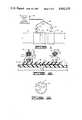
- FIG. 1is a side view of an electric heat weldable thermoplastic sleeve having the ends of a pair of pipe sections inserted therein with the electric power and control apparatus of the present invention illustrated schematically in relation thereto;
- FIG. 2is an enlarged cross-sectional view of portions of the fitting, plastic pipe sections and electric power and control apparatus of FIG. 1;
- FIG. 3is a partial top view taken along line 3--3 of FIG. 2;
- FIG. 4is an enlarged view of one of the connectors of the electric power and control apparatus of FIG. 1;
- FIG. 5is a bottom view taken along line 5--5 of FIG. 4;
- FIG. 6is a graph showing the current-time relationships of different fittings.
- FIG. 7is a schematic illustration of the electric power and control apparatus of the present invention connected to a thermoplastic fitting having a resistance heating element disposed therein.
- an electric heat weldable thermoplastic sleeve 10is illustrated with the ends of a pair of thermoplastic pipe sections 12 and 14 inserted therein.
- the sleeve 10includes a pair of electric contact connectors 16 and 18 attached thereto for receiving complementary electric contactors 20 and 22 attached to the ends of electric cables 24 and 26, respectively.
- the cables 24 and 26are connected to an electric power and control apparatus, generally designated by the numeral 30, which will be described in detail hereinbelow.
- the thermoplastic fitting 10includes an electric resistance heating element 28 disposed therein adjacent portions of the interior surface 32 thereof.
- the resistance heating elementcan take various forms, but preferably is a coil formed of electric resistance heating wire disposed in a spiral winding within the thermoplastic material forming the sleeve 10 adjacent the portions of the interior surface 32 which are to be welded to the exterior surfaces of the pipe sections 12 and 14.
- the opposite ends of the heating wire 28are connected to upstanding electric contact pins 34 and 36 disposed within the connectors 16 and 18.
- the complementary connectors 20 and 22 of the electric power and control apparatus 30are adapted for removable connection to the connectors 16 and 18 of the sleeve 10.
- the connectors 20 and 22include electric contact sockets 38 and 40, respectively, for engagement with the electric contact pins 34 and 36 of the connectors 16 and 18.
- the socket contact 38is connected to a wire 39 extending through the cable 24 and the socket contact 40 is connected to a wire 41 extending through the cable 26.
- the connector 22also includes a temperature sensing device 42 such as a thermister, RTD, or thermocouple positioned in heat conducting relationship with the socket contact 40 which is connected to a multiple lead wire 43 also extending through the cable 26.
- the device 42senses the temperature of the contact pin 36 when the socket contact 40 is engaged with the pin 36. That is, when the connector 22 is connected to the connector 18 of the sleeve 10, the temperature sensing device 42 senses an initial temperature which is representative of the outside surface temperature of the entire sleeve 10.
- the connector 16 of the fitting 10includes one or more (preferably one to nine) longitudinal code ridges 31 molded around the inside periphery thereof. As illustrated in FIG. 3, one or more of the ridges 31 can be enlarged so that it also functions as a position guide for the complementary contactor 20.
- Each size of fitting 10will include a connector 16 having a particular number and/or arrangement of code ridges 31 molded therein indicating that particular size. For example, the arrangement illustrated in FIG. 3 (5 ridges) could indicate a 5-inch size fitting.
- the complementary connector 20includes nine longitudinal recesses 33 which are complementary to the one to nine ridges 31 which may be included in the connector 16.
- the connector 20also includes a code ridge sensing device, such as a micro-switch 37, disposed in each of the recesses 33 to detect the presence of a code ridge therewithin.
- the micro-switches 37are electrically connected to leads 35 of a multiple lead wire 27 which extends through the cable 24.
- the connectors 20 and 22 attached to the cables 24 and 26are removably connected to the connectors 16 and 18 of the sleeve 10 whereby an electric circuit is completed between the heating element 28 of the fitting 10 and the electric power and control apparatus 30.
- the electric power and control apparatus 30operates in the manner described hereinbelow to provide electric power to the heating element 28 which causes the heating element to heat the thermoplastic material forming the sleeve 10 and the thermoplastic material forming the ends of the pipe sections 12 and 14 inserted within the interior of the sleeve 10.
- the heatingcauses the thermoplastic material of the fitting 10 and pipe sections 12 and 14 to melt and fuse together to thereby form welds between the fitting 10 and the pipe sections 12 and 14.
- the electric power and control apparatus 30 of the present inventionis schematically illustrated connected to the heating element 28 of the sleeve 10 by way of the cables 24 and 26 and the connectors 16, 18, 20 and 22.
- the apparatus 30includes a controlled voltage electric power source 45 which is connected by means of the wires 39 and 41 extending through the cables 24 and 26 to the contact sockets 38 and 40 of the connectors 20 and 22.
- a low voltage electric power source 47is also included in the apparatus 30 which is connected to the wires 39 and 41 by wires 53 and 55, respectively.
- the contact sockets 38 and 40 of the connectors 20 and 22are connected to the contact pins 34 and 36 of the connectors 16 and 18 of the sleeve 10 which are in turn connected to the heating element 28 of the fitting 10.
- a current sensor 46 for sensing the current flowing from the power source 45 to the heating element 28is electrically connected to the power source 45 by a lead 59 with the output signal therefrom connected by a lead 48 to an electronic computer 50.
- a resistance sensor 57 for sensing the resistance of the heating element 28 when minimum voltage electric power is applied theretois electrically connected to the power source 47 by a lead 61 with the output signal therefrom connected to the computer 50 by a lead 63.
- the temperature sensing device 42previously described, is connected by the wire 43 attached thereto and extending through the cable 26 to the computer 50, and the microswitches 37 of the connector 20 are connected to the computer 50 by the multiple lead wire 27.
- a switch device 52such as a TRICAC or SCR is provided in the circuit between the heating element 28 and the power source 45 which is operably connected to the computer 50 by a lead 54.
- a similar switch device 65is provided in the circuit connecting the power source 47 to the wires 39 and 41 which is connected to the computer 50 by a lead 67.
- the computer 50includes a readout module 51 operably connected thereto for visually indicating various modes of operation of the apparatus 30 such as a shutdown due to a defective fitting, etc. Also, the computer 50 is connected to a communication interface 69 by a lead 70 which in turn can be connected to a modem 72, a second computer 74 and a printer 16.
- the connectors 20 and 22are first connected to the connectors 16 and 18 of the fitting 10.
- the computer 50first closes the switch device 65 thereby completing a circuit between the low voltage electric power source 47 and the heating element 28 of the fitting 10 by way of the wires 39, 41, 53 and 55 connected therebetween.
- the low voltage electric power applied to the heating element 28is at a minimum level sufficient for the resistance sensor 57 to measure the resistance of the element 28, but too low to significantly heat the element.
- the resistance value so measuredis communicated to the computer 50 by the lead 63 and the computer 50 then opens the switch device 65.
- the computer 50determines the initial temperature of the element 28 which corresponds to the measured resistance value, and the initial outside surface temperature of the fitting 10 is sensed by the computer 50 by means of the temperature sensing device 42 and the wire 43 connected thereto. Also, the computer 50 senses the size of the fitting 10 by means of the code ridges in the connector 16, the micro-switches 37 of the connector 20 activated thereby and the wire 27 connected thereto.
- the computer 50next closes the switch device 52 thereby completing a circuit between the controlled voltage electric power source 45 and the heating element 28 by way of the wires 39 and 41 connected therebetween.
- the computer 50senses the initial magnitude of the current flowing through the heating element 28 by means of the current sensor 46 and lead 48.
- the initial temperature of the heating coil 28 and the initial magnitude of the current flowing therethroughare compared by the computer 50 with predetermined current levels for various sizes of fittings at various temperatures in the memory of the computer to determine the size of the fitting being welded.
- Such sizeis compared to the size of fitting indicated by the micro-switches 37, and if the same, the supply of controlled voltage electric power to the element 28 is continued, and the total time such power should be supplied to the element 28 to insure the making of a high quality weld is determined.
- FIG. 6the current-time relationship during the making of a high quality weld for two different sizes of fittings using controlled electric power is illustrated graphically.
- the top curve, designated by the numeral 60represents the welding process for a two-inch sleeve and the bottom curve, designated by the numeral 62, represents the welding process for a one-inch sleeve.
- the current levelsare different for the different sizes of sleeve, and each size and type of electrically heat weldable thermoplastic fitting has a current-time relationship which is characteristic of that fitting when a high quality weld is formed using a proper quantity of controlled electric power.
- the computer 50includes such current-time relationship information for a variety of electric heat weldable thermoplastic fittings in the memory thereof whereby the computer 50 can make the comparisons described and identify the size of fitting being welded from the initial magnitude of current flowing through the heating element.
- the computerdetermines the total time the controlled electric power should be supplied to the heating element for the making of a high quality weld from the information in memory and the initial temperature of the fitting. For example, referring to FIG. 6, if the initial magnitude of the current flowing through the heating element of a fitting is that designated by the numeral 64, the computer will determine that the fitting is a two-inch sleeve represented by the curve 60. The computer will also then determine from the curve 60 that the total time the controlled electric power should be supplied to the heating element for the making of a high quality weld is the time designated by the numeral 66.
- the computer 50continues to sense the magnitude of the current flowing through the heating element of the fitting being welded over the time the controlled electric power is supplied thereto and compares such magnitude at predetermined time intervals with predetermined current levels for the size of fitting being welded, i.e., for the two-inch sleeve of FIG. 6, the computer would compare the actual current level with the current levels of the curve 60 at frequent predetermined time intervals. As long as the sensed current levels are substantially the same as the current levels in memory for the size of fitting being welded, the computer continues the welding process to the total time determined to be required for the making of a high quality weld. If the sensed current levels deviate from the current levels in memory, as for example the deviation shown by the dashed line 68 of FIG. 6, the computer 50 determines the welding process is proceeding abnormally and terminates the welding process by turning off the electric power. The operator of the apparatus 30 is informed of the shutdown and the reason therefor by way of the readout 51.
- the initial temperature of the outside surface of the fitting 10 and the initial temperature of the heating element 28 of the fitting 10 sensed by the computer 50 as described abovecan be utilized by the computer 50 to determine if increases or decreases in the determined total time the constant voltage electric power should be supplied to the heating element are required to cause the melting of the required quantity of thermoplastic material. That is, based on such temperatures and the size of fitting, the computer 50 can calculate the total time required for the optimum quantity of thermoplastic material making up the fitting being welded and the pipe sections in contact therewith to melt and adjust the previously determined total time if necessary.
- the computer 50terminates the supply of electric power from the power source 47 to the heating element 28 of the fitting 10 being welded by operation of the switch device 52.
- the computer 50again measures the resistance of the element 28 and determines the final temperature thereof in the same manner as described above for measuring the initial temperature of the element 28.
- alternating currentis supplied to the heating element of the fitting being welded by the controlled voltage electric power source 45 of the apparatus 30.
- the frequency of the alternating currentis adjusted to that frequency which best causes the fitting being welded to vibrate as a result of the magnetic fields produced by the alternating current flowing through the heating element of the fitting. Such vibration facilitates and promotes the fusing of the softened thermoplastic materials of the fitting and other plastic members being welded thereto.
- conductive metallic materialcan be attached to or included in the weldable thermoplastic fittings.
- iron filings 29can be suspended in the thermoplastic material forming the fitting 10.
- the computer 50records in its memory the various temperatures, current magnitudes and other variables sensed and determined during the welding process.
- the computer 50can record the initial temperature of the outside surface of the fitting, the initial temperature of the heating element of the fitting, the size of the fitting, the determined time the constant voltage electric power should be supplied to the fitting, the magnitudes of current flowing over the time constant voltage electric power is supplied to the heating element of the fitting, the final temperature of the heating element, and the total time the constant voltage electric power is supplied to the heating element.
- Such recorded informationcan be communicated to a second computer 74 at a remote location by way of the communication interface 69 and a modem 72 connected thereto.
- the informationcan be printed by a printer 76 connected to the computer 74 or utilized in any other desired way. If the supply of electric power is terminated as a result of the welding process proceeding abnormally, the nature of the abnormality will be apparent from the recorded information.
Landscapes
- Engineering & Computer Science (AREA)
- Mechanical Engineering (AREA)
- Physics & Mathematics (AREA)
- Thermal Sciences (AREA)
- Lining Or Joining Of Plastics Or The Like (AREA)
Abstract
Description
Claims (15)
Priority Applications (8)
| Application Number | Priority Date | Filing Date | Title |
|---|---|---|---|
| US06/823,682US4642155A (en) | 1985-05-16 | 1986-01-29 | Thermoplastic fitting electric heat welding method and apparatus |
| GB8608888AGB2174955B (en) | 1985-05-16 | 1986-04-11 | Thermoplastic fitting electric heat welding method and apparatus |
| KR1019860003430AKR900007349B1 (en) | 1985-05-16 | 1986-05-01 | Thermoplastic fitting electric heat welding method and apparatus |
| CN86103309ACN1006368B (en) | 1985-05-16 | 1986-05-13 | Thermoplastic fitting electric heat welding method and apparatus |
| CA000509136ACA1255869A (en) | 1985-05-16 | 1986-05-14 | Thermoplastic fitting electric heat welding method and apparatus |
| MYPI87000842AMY100793A (en) | 1985-05-16 | 1987-06-18 | Thermoplastic fitting electric heat welding method and apparatus. |
| SG46590ASG46590G (en) | 1985-05-16 | 1990-06-30 | Thermoplastic fitting electric heat welding method and apparatus |
| HK649/90AHK64990A (en) | 1985-05-16 | 1990-08-16 | Thermoplastic fitting electric heat welding method and apparatus |
Applications Claiming Priority (2)
| Application Number | Priority Date | Filing Date | Title |
|---|---|---|---|
| US06/734,836US4602148A (en) | 1985-05-16 | 1985-05-16 | Thermoplastic fitting electric heat welding method and apparatus |
| US06/823,682US4642155A (en) | 1985-05-16 | 1986-01-29 | Thermoplastic fitting electric heat welding method and apparatus |
Related Parent Applications (1)
| Application Number | Title | Priority Date | Filing Date |
|---|---|---|---|
| US06/734,836Continuation-In-PartUS4602148A (en) | 1985-05-16 | 1985-05-16 | Thermoplastic fitting electric heat welding method and apparatus |
Publications (1)
| Publication Number | Publication Date |
|---|---|
| US4642155Atrue US4642155A (en) | 1987-02-10 |
Family
ID=27112793
Family Applications (1)
| Application Number | Title | Priority Date | Filing Date |
|---|---|---|---|
| US06/823,682Expired - LifetimeUS4642155A (en) | 1985-05-16 | 1986-01-29 | Thermoplastic fitting electric heat welding method and apparatus |
Country Status (7)
| Country | Link |
|---|---|
| US (1) | US4642155A (en) |
| KR (1) | KR900007349B1 (en) |
| CN (1) | CN1006368B (en) |
| CA (1) | CA1255869A (en) |
| GB (1) | GB2174955B (en) |
| HK (1) | HK64990A (en) |
| SG (1) | SG46590G (en) |
Cited By (45)
| Publication number | Priority date | Publication date | Assignee | Title |
|---|---|---|---|---|
| AU577189B2 (en)* | 1985-05-16 | 1988-09-15 | Central Plastics Company | Welding thermoplastic pipe joint |
| US4795877A (en)* | 1985-09-12 | 1989-01-03 | Fusion Plastics Limited | Fault detecting device for welded pipe joints |
| DE3810795A1 (en)* | 1988-03-30 | 1989-10-12 | Huerner Gmbh | ELECTRIC WELDING MACHINE FOR THE AUTOMATIC WELDING OF HEATING TURN FITTINGS |
| US4894112A (en)* | 1987-11-13 | 1990-01-16 | Lippman Glenn W | Method and apparatus for joining overlapping sheets of thermally sealable material |
| US4978837A (en)* | 1990-04-13 | 1990-12-18 | Central Plastics Company | Method and apparatus for electrically heat welding thermoplastic fittings |
| US5013376A (en)* | 1989-10-02 | 1991-05-07 | Mcelroy Manufacturing, Inc. | Programmable computer controlled pipe fusion device |
| US5141580A (en)* | 1989-11-29 | 1992-08-25 | Gaz De France | Connection component for together plastic elements by thermal welding |
| US5223189A (en)* | 1992-01-07 | 1993-06-29 | Gundle Lining Systems, Inc. | Method of sealing lateral connections for pipe liners |
| WO1993019563A1 (en)* | 1992-03-16 | 1993-09-30 | Sonne Medical | Automatically programmable self-regulating disposable electric immersion heater apparatus and method for medical use |
| US5280158A (en)* | 1992-05-01 | 1994-01-18 | Matava Stephen J | Controller for electric heaters for internal combustion engine |
| US5423938A (en)* | 1993-08-16 | 1995-06-13 | Hofius, Sr.; David V. | Hot air cold form staking device |
| US5518560A (en)* | 1994-09-26 | 1996-05-21 | Ford Motor Company | Method and system for controlling electromagnetic field generator for adhesive curing and sensing device for use therein |
| US5573613A (en)* | 1995-01-03 | 1996-11-12 | Lunden; C. David | Induction thermometry |
| US5620625A (en)* | 1992-06-01 | 1997-04-15 | Gaz De France (Service National) | Method of butt-welding two plastic parts with an identifying code, using an automatically controlled electro-welding machine |
| US5624511A (en)* | 1994-10-27 | 1997-04-29 | Glenn W. Lippman | Method and apparatus for joining heat sealable material |
| US5639394A (en)* | 1995-01-31 | 1997-06-17 | Kerotest Manufacturing Corp. | Electrofusion formed valve assembly |
| US5660669A (en)* | 1994-12-09 | 1997-08-26 | The Boeing Company | Thermoplastic welding |
| US5705796A (en)* | 1991-10-18 | 1998-01-06 | The Boeing Company | Reinforced composites formed using induction thermoplastic welding |
| US5710412A (en)* | 1994-09-28 | 1998-01-20 | The Boeing Company | Fluid tooling for thermoplastic welding |
| US5760379A (en)* | 1995-10-26 | 1998-06-02 | The Boeing Company | Monitoring the bond line temperature in thermoplastic welds |
| US5788789A (en)* | 1995-06-08 | 1998-08-04 | George Fischer Sloane, Inc. | Power device for fusing plastic pipe joints |
| US5847375A (en) | 1991-04-05 | 1998-12-08 | The Boeing Company | Fastenerless bonder wingbox |
| US5911895A (en)* | 1996-03-28 | 1999-06-15 | Georg Fischer Rohrleitungssyteme Ag | Device for welding molded plastic parts permitting simultaneous and mutually independent welding processes |
| US5948189A (en)* | 1997-12-05 | 1999-09-07 | Global Utility Technologies Ltd. | Automated sidewall fusing apparatus |
| GB2362197A (en)* | 2000-04-13 | 2001-11-14 | Glynwed Pipe Systems Ltd | Method of joining components including measuring the resistance of a first component |
| US6441352B1 (en) | 2000-01-05 | 2002-08-27 | Ef Technologies, Inc. | Apparatus for electrically heat welding thermoplastic fittings and method of using the same |
| US6680464B1 (en) | 2000-07-28 | 2004-01-20 | Zurn Industries, Inc. | Electrofusion joining control device |
| US20040251575A1 (en)* | 2003-06-13 | 2004-12-16 | Bryan St. Onge | Fusion process for conduit |
| US20060157466A1 (en)* | 2005-01-14 | 2006-07-20 | Mitsuhiko Miyazaki | Control system for battery powered heating device |
| US20060197338A1 (en)* | 2005-03-07 | 2006-09-07 | Ziu Christopher G | Electro-fusion joining system for thermoplastic piping systems |
| US20080257604A1 (en)* | 2007-04-13 | 2008-10-23 | Underground Solutions Technologies Group, Inc. | Conduit, manufacture thereof and fusion process therefor |
| US20090079183A1 (en)* | 2007-09-24 | 2009-03-26 | Cantex, Inc. | Non-Metallic Raceway for Wirinig and Fiber Optic Cable and Method of Forming Raceway |
| US20090216269A1 (en)* | 2006-04-18 | 2009-08-27 | Axya Medical, Inc, | Multicomponent fused suture loop and apparatus for making same |
| US20100288011A1 (en)* | 2009-05-15 | 2010-11-18 | Ef Technologies, Inc. | Apparatus and method for portable calibration of electrofusion controllers |
| US7842769B1 (en) | 2003-06-13 | 2010-11-30 | Underground Solutions Technologies Group, Inc. | Polyvinyl chloride formulations |
| USD719596S1 (en) | 2012-12-20 | 2014-12-16 | Sfs Intec Holding Ag | Induction apparatus |
| RU2744141C2 (en)* | 2019-05-13 | 2021-03-03 | Федеральное государственное бюджетное учреждение науки Федеральный исследовательский центр "Якутский научный центр Сибирского отделения Российской академии наук" | Method of welding plastic pipes by connecting parts with an embedded heater |
| US20210245446A1 (en)* | 2020-02-11 | 2021-08-12 | Georg Fischer Wavin Ag | Electroweld fitting |
| US11525534B2 (en) | 2018-08-14 | 2022-12-13 | Reliance Worldwide Corporation | Tubular connector |
| US11802643B2 (en) | 2018-04-24 | 2023-10-31 | Reliance Worldwide Corporation | Fluid connector |
| EP3840941B1 (en) | 2019-05-22 | 2024-03-13 | agru Kunststofftechnik Gesellschaft m.b.H. | Method for producing a welded connection, and welding device |
| US12104730B2 (en) | 2020-03-13 | 2024-10-01 | Reliance Worldwide Corporation | Push-to-connect fitting providing an insertion indication |
| US12228231B2 (en) | 2022-09-30 | 2025-02-18 | Reliance Worldwide Corporation | Plumbing connector |
| US12338928B2 (en) | 2018-08-14 | 2025-06-24 | Reliance Worldwide Corporation | Plumbing fitting |
| US12345361B2 (en) | 2018-08-14 | 2025-07-01 | Reliance Worldwide Corporation | Plumbing fitting |
Families Citing this family (4)
| Publication number | Priority date | Publication date | Assignee | Title |
|---|---|---|---|---|
| GB8910509D0 (en)* | 1989-05-08 | 1989-06-21 | British Gas Plc | Identification of electro-fusion fittings |
| CN105050798A (en)* | 2013-03-22 | 2015-11-11 | 欧利生电气株式会社 | Composite-material joining device, method for producing joined body, and joined body |
| CN106891112A (en)* | 2017-04-01 | 2017-06-27 | 深圳市鑫华威机电设备有限公司 | The welding control method and system of semi-automatic welder |
| CN110315763B (en)* | 2019-07-03 | 2022-03-15 | 天津市津能管业有限公司 | Automatic hot-melt welding machine and welding method |
Citations (7)
| Publication number | Priority date | Publication date | Assignee | Title |
|---|---|---|---|---|
| US4117311A (en)* | 1976-03-22 | 1978-09-26 | Von Roll Ag. | Electric welding muff |
| US4147926A (en)* | 1975-12-18 | 1979-04-03 | Geberit Ag | Electrical heatable muff and process for its manufacture |
| US4334146A (en)* | 1978-04-28 | 1982-06-08 | Werner Sturm | Method and apparatus for joining thermoplastic line elements |
| US4349219A (en)* | 1978-04-21 | 1982-09-14 | Von Roll A.G. | Welding muff of thermoplastic material |
| US4486650A (en)* | 1981-09-30 | 1984-12-04 | Fusion Plastics Ltd. | Electro-fusion fitting and control apparatus therefor |
| US4511791A (en)* | 1983-04-25 | 1985-04-16 | Owens-Corning Fiberglas Corporation | Electronic balance meter |
| US4602148A (en)* | 1985-05-16 | 1986-07-22 | Central Plastics Company | Thermoplastic fitting electric heat welding method and apparatus |
Family Cites Families (3)
| Publication number | Priority date | Publication date | Assignee | Title |
|---|---|---|---|---|
| GB1520556A (en)* | 1975-11-05 | 1978-08-09 | Windmoeller & Hoelscher | Apparatus for regulating the temperature of electrically heated welding bands |
| US4416713A (en)* | 1980-07-24 | 1983-11-22 | Brooks Ronald H | Method and apparatus for joining abutting edges of sheet material |
| GB2137026B (en)* | 1983-03-24 | 1987-04-29 | Fusion Plastics Ltd | Coupling electrofusion fitting to energy source and control equipment |
- 1986
- 1986-01-29USUS06/823,682patent/US4642155A/ennot_activeExpired - Lifetime
- 1986-04-11GBGB8608888Apatent/GB2174955B/ennot_activeExpired
- 1986-05-01KRKR1019860003430Apatent/KR900007349B1/ennot_activeExpired
- 1986-05-13CNCN86103309Apatent/CN1006368B/ennot_activeExpired
- 1986-05-14CACA000509136Apatent/CA1255869A/ennot_activeExpired
- 1990
- 1990-06-30SGSG46590Apatent/SG46590G/enunknown
- 1990-08-16HKHK649/90Apatent/HK64990A/ennot_activeIP Right Cessation
Patent Citations (7)
| Publication number | Priority date | Publication date | Assignee | Title |
|---|---|---|---|---|
| US4147926A (en)* | 1975-12-18 | 1979-04-03 | Geberit Ag | Electrical heatable muff and process for its manufacture |
| US4117311A (en)* | 1976-03-22 | 1978-09-26 | Von Roll Ag. | Electric welding muff |
| US4349219A (en)* | 1978-04-21 | 1982-09-14 | Von Roll A.G. | Welding muff of thermoplastic material |
| US4334146A (en)* | 1978-04-28 | 1982-06-08 | Werner Sturm | Method and apparatus for joining thermoplastic line elements |
| US4486650A (en)* | 1981-09-30 | 1984-12-04 | Fusion Plastics Ltd. | Electro-fusion fitting and control apparatus therefor |
| US4511791A (en)* | 1983-04-25 | 1985-04-16 | Owens-Corning Fiberglas Corporation | Electronic balance meter |
| US4602148A (en)* | 1985-05-16 | 1986-07-22 | Central Plastics Company | Thermoplastic fitting electric heat welding method and apparatus |
Cited By (69)
| Publication number | Priority date | Publication date | Assignee | Title |
|---|---|---|---|---|
| AU577189B2 (en)* | 1985-05-16 | 1988-09-15 | Central Plastics Company | Welding thermoplastic pipe joint |
| US4795877A (en)* | 1985-09-12 | 1989-01-03 | Fusion Plastics Limited | Fault detecting device for welded pipe joints |
| US4894112A (en)* | 1987-11-13 | 1990-01-16 | Lippman Glenn W | Method and apparatus for joining overlapping sheets of thermally sealable material |
| DE3810795A1 (en)* | 1988-03-30 | 1989-10-12 | Huerner Gmbh | ELECTRIC WELDING MACHINE FOR THE AUTOMATIC WELDING OF HEATING TURN FITTINGS |
| US5013376A (en)* | 1989-10-02 | 1991-05-07 | Mcelroy Manufacturing, Inc. | Programmable computer controlled pipe fusion device |
| US5141580A (en)* | 1989-11-29 | 1992-08-25 | Gaz De France | Connection component for together plastic elements by thermal welding |
| US4978837A (en)* | 1990-04-13 | 1990-12-18 | Central Plastics Company | Method and apparatus for electrically heat welding thermoplastic fittings |
| US5847375A (en) | 1991-04-05 | 1998-12-08 | The Boeing Company | Fastenerless bonder wingbox |
| US7126096B1 (en) | 1991-04-05 | 2006-10-24 | Th Boeing Company | Resistance welding of thermoplastics in aerospace structure |
| US5705796A (en)* | 1991-10-18 | 1998-01-06 | The Boeing Company | Reinforced composites formed using induction thermoplastic welding |
| US5223189A (en)* | 1992-01-07 | 1993-06-29 | Gundle Lining Systems, Inc. | Method of sealing lateral connections for pipe liners |
| WO1993019563A1 (en)* | 1992-03-16 | 1993-09-30 | Sonne Medical | Automatically programmable self-regulating disposable electric immersion heater apparatus and method for medical use |
| US5408577A (en)* | 1992-03-16 | 1995-04-18 | Sonne Medical | Method and heater apparatus with protective fuse for medical applications |
| US5280158A (en)* | 1992-05-01 | 1994-01-18 | Matava Stephen J | Controller for electric heaters for internal combustion engine |
| US5620625A (en)* | 1992-06-01 | 1997-04-15 | Gaz De France (Service National) | Method of butt-welding two plastic parts with an identifying code, using an automatically controlled electro-welding machine |
| US5423938A (en)* | 1993-08-16 | 1995-06-13 | Hofius, Sr.; David V. | Hot air cold form staking device |
| US5518560A (en)* | 1994-09-26 | 1996-05-21 | Ford Motor Company | Method and system for controlling electromagnetic field generator for adhesive curing and sensing device for use therein |
| US5601365A (en)* | 1994-09-26 | 1997-02-11 | Ford Motor Company | Sensing device for controlling electromagnetic field generator for adhesive curing |
| US5710412A (en)* | 1994-09-28 | 1998-01-20 | The Boeing Company | Fluid tooling for thermoplastic welding |
| US5624511A (en)* | 1994-10-27 | 1997-04-29 | Glenn W. Lippman | Method and apparatus for joining heat sealable material |
| US5660669A (en)* | 1994-12-09 | 1997-08-26 | The Boeing Company | Thermoplastic welding |
| US5753068A (en)* | 1994-12-09 | 1998-05-19 | Mittleider; John A. | Thermoplastic welding articulated skate |
| US5833799A (en)* | 1994-12-09 | 1998-11-10 | The Boeing Company | Articulated welding skate |
| US5573613A (en)* | 1995-01-03 | 1996-11-12 | Lunden; C. David | Induction thermometry |
| US5639394A (en)* | 1995-01-31 | 1997-06-17 | Kerotest Manufacturing Corp. | Electrofusion formed valve assembly |
| US5788789A (en)* | 1995-06-08 | 1998-08-04 | George Fischer Sloane, Inc. | Power device for fusing plastic pipe joints |
| US5760379A (en)* | 1995-10-26 | 1998-06-02 | The Boeing Company | Monitoring the bond line temperature in thermoplastic welds |
| US5911895A (en)* | 1996-03-28 | 1999-06-15 | Georg Fischer Rohrleitungssyteme Ag | Device for welding molded plastic parts permitting simultaneous and mutually independent welding processes |
| US5948189A (en)* | 1997-12-05 | 1999-09-07 | Global Utility Technologies Ltd. | Automated sidewall fusing apparatus |
| US6441352B1 (en) | 2000-01-05 | 2002-08-27 | Ef Technologies, Inc. | Apparatus for electrically heat welding thermoplastic fittings and method of using the same |
| GB2362197A (en)* | 2000-04-13 | 2001-11-14 | Glynwed Pipe Systems Ltd | Method of joining components including measuring the resistance of a first component |
| US6680464B1 (en) | 2000-07-28 | 2004-01-20 | Zurn Industries, Inc. | Electrofusion joining control device |
| US8796407B2 (en) | 2003-06-13 | 2014-08-05 | Underground Solutions Technologies Group, Inc. | Polyvinyl chloride formulations |
| EP2383105A2 (en) | 2003-06-13 | 2011-11-02 | Underground Solutions Technologies Group, Inc. | Fusion process for conduit |
| US8178640B2 (en) | 2003-06-13 | 2012-05-15 | Underground Solutions Technologies Group, Inc. | Polyvinyl chloride formulations |
| US20040251575A1 (en)* | 2003-06-13 | 2004-12-16 | Bryan St. Onge | Fusion process for conduit |
| US8128853B2 (en) | 2003-06-13 | 2012-03-06 | Underground Solutions Technologies Group, Inc. | Fusion process for conduit |
| US6982051B2 (en) | 2003-06-13 | 2006-01-03 | Underground Solutions Technologies Group, Inc. | Fusion process for conduit |
| US9023263B2 (en) | 2003-06-13 | 2015-05-05 | Underground Solutions Technologies Group, Inc. | Fusion process for conduit |
| US8906188B2 (en) | 2003-06-13 | 2014-12-09 | Underground Solutions Technologies Group, Inc. | Fusion process for conduit |
| US8058378B1 (en) | 2003-06-13 | 2011-11-15 | Underground Solutions Technologies Group, Inc. | Polyvinyl chloride formulations |
| US8569436B2 (en) | 2003-06-13 | 2013-10-29 | Underground Solutions Technologies Group, Inc. | Polyvinyl chloride formulations |
| US20060071365A1 (en)* | 2003-06-13 | 2006-04-06 | Underground Solutions Technologies Group, Inc. | Fusion process for conduit |
| US7842769B1 (en) | 2003-06-13 | 2010-11-30 | Underground Solutions Technologies Group, Inc. | Polyvinyl chloride formulations |
| US7915366B1 (en) | 2003-06-13 | 2011-03-29 | Underground Solutions Technologies Group, Inc. | Polyvinyl chloride formulations |
| US7608805B2 (en)* | 2005-01-14 | 2009-10-27 | Hakko Corporation | Control system for battery powered heating device |
| US20060157466A1 (en)* | 2005-01-14 | 2006-07-20 | Mitsuhiko Miyazaki | Control system for battery powered heating device |
| US20060202471A1 (en)* | 2005-03-07 | 2006-09-14 | Weisbond Bradley K | Electro-fusion joining system for thermoplastic piping systems |
| US20060197338A1 (en)* | 2005-03-07 | 2006-09-07 | Ziu Christopher G | Electro-fusion joining system for thermoplastic piping systems |
| US20090216269A1 (en)* | 2006-04-18 | 2009-08-27 | Axya Medical, Inc, | Multicomponent fused suture loop and apparatus for making same |
| US20080257604A1 (en)* | 2007-04-13 | 2008-10-23 | Underground Solutions Technologies Group, Inc. | Conduit, manufacture thereof and fusion process therefor |
| US8167338B2 (en) | 2007-09-24 | 2012-05-01 | Cantex, Inc. | Non-metallic raceway for wiring and fiber optic cable and method of forming raceway |
| US20090079183A1 (en)* | 2007-09-24 | 2009-03-26 | Cantex, Inc. | Non-Metallic Raceway for Wirinig and Fiber Optic Cable and Method of Forming Raceway |
| US20100288011A1 (en)* | 2009-05-15 | 2010-11-18 | Ef Technologies, Inc. | Apparatus and method for portable calibration of electrofusion controllers |
| US9174299B2 (en)* | 2009-05-15 | 2015-11-03 | Ef Technologies, Inc. | Apparatus and method for portable calibration of electrofusion controllers |
| USD719596S1 (en) | 2012-12-20 | 2014-12-16 | Sfs Intec Holding Ag | Induction apparatus |
| US11802643B2 (en) | 2018-04-24 | 2023-10-31 | Reliance Worldwide Corporation | Fluid connector |
| USD1079903S1 (en) | 2018-08-14 | 2025-06-17 | Reliance Worldwide Corporation | Tubular connector |
| US11525534B2 (en) | 2018-08-14 | 2022-12-13 | Reliance Worldwide Corporation | Tubular connector |
| US12049974B2 (en) | 2018-08-14 | 2024-07-30 | Reliance Worldwide Corporation | Tubular connector |
| US12345361B2 (en) | 2018-08-14 | 2025-07-01 | Reliance Worldwide Corporation | Plumbing fitting |
| US12338928B2 (en) | 2018-08-14 | 2025-06-24 | Reliance Worldwide Corporation | Plumbing fitting |
| RU2744141C2 (en)* | 2019-05-13 | 2021-03-03 | Федеральное государственное бюджетное учреждение науки Федеральный исследовательский центр "Якутский научный центр Сибирского отделения Российской академии наук" | Method of welding plastic pipes by connecting parts with an embedded heater |
| EP3840941B1 (en) | 2019-05-22 | 2024-03-13 | agru Kunststofftechnik Gesellschaft m.b.H. | Method for producing a welded connection, and welding device |
| US11987010B2 (en) | 2019-05-22 | 2024-05-21 | Agru Kunststofftechnik Gesellschaft M.B.H. | Method for producing a welded connection, and welding device |
| US20210245446A1 (en)* | 2020-02-11 | 2021-08-12 | Georg Fischer Wavin Ag | Electroweld fitting |
| US12162223B2 (en)* | 2020-02-11 | 2024-12-10 | Georg Fischer Wavin Ag | Electroweld fitting |
| US12104730B2 (en) | 2020-03-13 | 2024-10-01 | Reliance Worldwide Corporation | Push-to-connect fitting providing an insertion indication |
| US12228231B2 (en) | 2022-09-30 | 2025-02-18 | Reliance Worldwide Corporation | Plumbing connector |
Also Published As
| Publication number | Publication date |
|---|---|
| CN1006368B (en) | 1990-01-10 |
| KR860008856A (en) | 1986-12-18 |
| GB2174955A (en) | 1986-11-19 |
| KR900007349B1 (en) | 1990-10-08 |
| GB2174955B (en) | 1989-01-18 |
| HK64990A (en) | 1990-08-24 |
| GB8608888D0 (en) | 1986-05-14 |
| CN86103309A (en) | 1986-11-12 |
| SG46590G (en) | 1990-08-17 |
| CA1255869A (en) | 1989-06-20 |
Similar Documents
| Publication | Publication Date | Title |
|---|---|---|
| US4642155A (en) | Thermoplastic fitting electric heat welding method and apparatus | |
| US4684789A (en) | Thermoplastic fitting electric welding method and apparatus | |
| US4602148A (en) | Thermoplastic fitting electric heat welding method and apparatus | |
| US4978837A (en) | Method and apparatus for electrically heat welding thermoplastic fittings | |
| CA1193819A (en) | Electro-fusion fitting | |
| US4631107A (en) | Thermoplastic fitting electric heat welding apparatus | |
| WO1995016557A2 (en) | Electrofusion fastening apparatus | |
| US5500510A (en) | Method of automatically controlling the fusion process between thermoplastic articles | |
| JPS60157833A (en) | Connector used for electric fusing type fitting of thermoplastic material | |
| JPH0743067B2 (en) | Electrofusion joint defect display method | |
| JP2513757B2 (en) | How to connect electric fusion type plastic pipes | |
| EP0403260B1 (en) | Solder joint system | |
| JPS63160822A (en) | Electric fusing-equipment | |
| JP2578104B2 (en) | Electric welding equipment | |
| JP2962999B2 (en) | Control method of energization of electric fusion joint | |
| JPH0972482A (en) | Current-carrying control method for electric fusion coupling | |
| JP2730884B2 (en) | Electric welding equipment | |
| JP3438338B2 (en) | Energization control method of electrofusion type pipe joint | |
| JP2819010B2 (en) | Electric welding equipment | |
| JPH02196628A (en) | Electric welding device | |
| US6590189B2 (en) | Method of measuring a welding voltage at a heating coil of a heating coil fitting and a heating coil welding apparatus | |
| JP2819011B2 (en) | Electric welding equipment | |
| JPH07164532A (en) | Electric fusion welding equipment | |
| JPH02231127A (en) | Method and apparatus for fusion of electrofusion joint | |
| JP2730885B2 (en) | Electric welding equipment |
Legal Events
| Date | Code | Title | Description |
|---|---|---|---|
| AS | Assignment | Owner name:CENTRAL PLASTICS COMPANY, SHAWNEE, OKLAHOMA, A COR Free format text:ASSIGNMENT OF ASSIGNORS INTEREST.;ASSIGNOR:RAMSEY, RUSSEL G.;REEL/FRAME:004511/0709 Effective date:19860128 | |
| STCF | Information on status: patent grant | Free format text:PATENTED CASE | |
| FEPP | Fee payment procedure | Free format text:PAYOR NUMBER ASSIGNED (ORIGINAL EVENT CODE: ASPN); ENTITY STATUS OF PATENT OWNER: SMALL ENTITY | |
| FPAY | Fee payment | Year of fee payment:4 | |
| FPAY | Fee payment | Year of fee payment:8 | |
| FPAY | Fee payment | Year of fee payment:12 | |
| AS | Assignment | Owner name:LOCAL OKLAHOMA BANK, N.A., OKLAHOMA Free format text:SECURITY AGREEMENT;ASSIGNOR:CENTRAL PLASTICS COMPANY;REEL/FRAME:012495/0072 Effective date:20001011 | |
| AS | Assignment | Owner name:BANK OF AMERICA, N.A., OKLAHOMA Free format text:SECURITY AGREEMENT;ASSIGNOR:CENTRAL PLASTICS COMPANY;REEL/FRAME:015044/0865 Effective date:20040730 | |
| AS | Assignment | Owner name:CENTRAL PLASTICS COMPANY, OKLAHOMA Free format text:RELEASE OF SECURITY INTEREST;ASSIGNOR:LOCAL OKLAHOMA BANK, FORMERLY LOCAL OKLAHOMA BANK, N.A.;REEL/FRAME:015147/0338 Effective date:20040611 |