US4641502A - Roof mount air conditioner - Google Patents
Roof mount air conditionerDownload PDFInfo
- Publication number
- US4641502A US4641502AUS06/883,581US88358186AUS4641502AUS 4641502 AUS4641502 AUS 4641502AUS 88358186 AUS88358186 AUS 88358186AUS 4641502 AUS4641502 AUS 4641502A
- Authority
- US
- United States
- Prior art keywords
- condenser
- compartment
- blower
- evaporator
- base pan
- Prior art date
- Legal status (The legal status is an assumption and is not a legal conclusion. Google has not performed a legal analysis and makes no representation as to the accuracy of the status listed.)
- Expired - Lifetime
Links
Images


Classifications
- B—PERFORMING OPERATIONS; TRANSPORTING
- B60—VEHICLES IN GENERAL
- B60H—ARRANGEMENTS OF HEATING, COOLING, VENTILATING OR OTHER AIR-TREATING DEVICES SPECIALLY ADAPTED FOR PASSENGER OR GOODS SPACES OF VEHICLES
- B60H1/00—Heating, cooling or ventilating [HVAC] devices
- B60H1/00357—Air-conditioning arrangements specially adapted for particular vehicles
- B60H1/00378—Air-conditioning arrangements specially adapted for particular vehicles for tractor or load vehicle cabins
- Y—GENERAL TAGGING OF NEW TECHNOLOGICAL DEVELOPMENTS; GENERAL TAGGING OF CROSS-SECTIONAL TECHNOLOGIES SPANNING OVER SEVERAL SECTIONS OF THE IPC; TECHNICAL SUBJECTS COVERED BY FORMER USPC CROSS-REFERENCE ART COLLECTIONS [XRACs] AND DIGESTS
- Y10—TECHNICAL SUBJECTS COVERED BY FORMER USPC
- Y10S—TECHNICAL SUBJECTS COVERED BY FORMER USPC CROSS-REFERENCE ART COLLECTIONS [XRACs] AND DIGESTS
- Y10S62/00—Refrigeration
- Y10S62/16—Roof and ceiling located coolers
Definitions
- This inventionrelates to self-contained air conditioning units of the mechanical or compressor type, and, more particularly, to an improved air conditioning unit adapted to be mounted on the roof of a recreational vehicle or the like for cooling the interior passenger space of the vehicle.
- RVrecreational vehicles
- Typical RV industry standardscall for the unit to be superposed to a standard 14" by 14" opening in the roof and ceiling of the recreational vehicle through which the cooled air is ducted downwardly from the air conditioning unit into the passenger space, and stale warm air is exhausted from the passenger space therebelow into the air conditioning unit for cooling and return of the same.
- a roof mount air conditioneris that manufactured by The Duo-Therm Corporation of LaGrange, Ind. as Duo-Therm Roof Mount Air Conditioner Model No. 57915-001.
- the air conditioning componentsare mounted on a sheet metal base pan which forms the main structural supporting component of the unit, and a removable shroud is attached over the base pan and components to provide protection from the elements and also to provide an aesthetically pleasing appearance for the unit as viewed from the exterior of the vehicle.
- a removable shroudis shown in U.S. Pat. No. Des. 206,103.
- the condenser coil of the air conditioning unitis arranged in the rear or aft end of the unit (relative to vehicle orientation) and grill openings are provided in the side walls of the shroud to admit exterior ambient air to the condenser compartment.
- a condenser fanusually an axial-flow fan, is mounted in this compartment to blow the exterior ambient air through the condenser coil to extract heat from the same.
- Such condenser cooling airis exhausted from the rear of the shroud, which may be entirely open or provided with vents in its rear wall to accommodate this flow back to ambient.
- an object of the present inventionis to provide an improved roof mount air conditioner for recreational vehicles or the like which has an equal or better cooling capacity with respect to equal size and weight prior art units, while at the same time providing a significantly reduced vertical dimension in order to impart an aesthetically pleasing "low profile" aspect when mounted on the roof of a recreational vehicle or the like.
- Another object of the present inventionis to provide an air conditioning unit of the aforementioned character in which the air inlets and outlets for the condenser compartment are essentially hidden from view to thereby further enhance the aesthetically pleasing appearance of the air conditioning unit.
- Another object of the present inventionis to provide an air conditioning unit of the aforementioned character which is better shielded by the cabinet shroud from inclement weather invasion, and which provides a more streamlined appearance and aerodynamically efficient housing for the air conditioning unit.
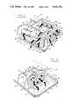
- FIG. 1is an exploded perspective view of a preferred, but exemplary, embodiment of a roof mount air conditioner constructed in accordance with the present invention, the shroud outer cover and shroud inner liner being exploded from the base of the unit.
- FIG. 2is a fragmentary perspective view of the rear or aft end of the air conditioner unit with the cabinet shroud made transparent and shown in phantom, and illustrating forced air flow through the condenser and compressor compartments with air flow arrows.
- FIG. 3is a fragmentary perspective view of the front or forward portion of the unit, the shroud again being shown in phantom and made transparent, and with air flow arrows illustrating forced air flow through the evaporator compartment of the unit.
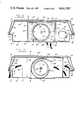
- FIG. 4is a top plan view of the air conditioning unit of FIGS. 1-3 with the shroud illustrated in phantom and made transparent.
- FIG. 5is an elevational view of the left hand or port side of the unit of FIGS. 1-4 as viewed looking in the direction of the arrow 5 in FIG. 4.
- FIG. 6is an elevational view of the rear or aft end of the air conditioner unit of FIGS. 1-5.
- FIGS. 7, 8, 9 and 10are vertical sectional views taken on the lines 7--7, 8--8, 9--9 and 10--10, respectively, of FIG. 4.
- FIG. 1a roof mount air conditioner 20 constructed in accordance with the present invention is illustrated In FIG. 1 with a shroud outer cover 22 and a shroud inner liner 24 exploded above the base subassembly 26 of the unit.
- Base subassembly 26comprises a base pan 28 made as a one-piece metal stamping which forms the main structural supporting component of the unit, on which the various air conditioning components and compartment bulkheads are mounted.
- the ornamental aesthetic aspects of the design of the shroud and base pan in assemblyare the subject of a co-pending United States design patent application Ser. No. b 635,622, filed July 30, 1984, (now U.S. Pat. No. Des. 284,025) in the name of William H. Armstrong and assigned to The Duo-Therm Corporation, the original assignee herein and assignor to the present asignee of record, Dometic Incorporated.
- base pan 28is a generally rectangular shape in plan view (FIG. 4) with the front half having slightly convergent side walls and with the corners of the base pan rounded.
- Base pan 28comprises a generally flat bottom wall 30, the outer periphery of which is bounded by upturned vertical wall portions comprising a front wall 32, rear wall 34, right-hand or starboard wall 36 and left-hand or port wall 38 which rise vertically approximately 3" (in one preferred working embodiment) from the bottom floor 30.
- each of the perimeter walls 32,34,36,38are integrally connected through a radius bend to a horizontal perimeter flange or "porch" extending outwardly of the associated perimeter wall so as to form front, rear, starboard and port flange portions 40,42,44,46, respectively, extending as one integral continuous ledge all the way around the perimeter of the base pan.
- Front flange portion 40has the narrowest or least projection dimension, for example, about 1/2", and, as will best be seen in FIG. 4, the starboard and port flange portions 44,46 have a gradually increasing horizontal projection dimension outwardly of the base pan increasing toward the rear of the unit, with the rear flange 42 having the maximum projection distance, for example, about 23/4".
- the perimeter horizontal porch flange 40,42,44,46 of base pan 28terminates at its outer peripheral edge in a integrally connected upwardly bent vertical edge flange defined by a front edge, rear edge, starboard and port edge portions 50,52,54,56, respectively, of uniform height and defining an upper edge in a common plane.
- Bottom wall 30 of base pan 28is provided with an air inlet opening 60 adjacent the front edge of the bottom wall, bounded by an integral upstanding peripheral flange 62 (FIG. 8).
- a rectangular air outlet opening 64(FIGS. 4 and 9) is provided in bottom wall 30 between air inlet 60 and the center of the unit, and is bounded by upwardly bent peripheral flanges 66,68,70,72 (FIGS. 8 and 9).
- bottom wall 30has in the rearward portion thereof a centrally located, downwardly depressed, rectangularly shaped portion 76 which extends below the remaining portion of bottom wall 30 about 1/4" and provides additional vertical clearance for accommodating condenser blower 206.
- the rear half of base pan 28is provided with a series of rows of openings for admitting and expelling ambient air to and from the compressor compartment of the air conditioning unit 20 in a manner to be described in more detail hereinafter.
- Approximately half of the ambient air inlet openingsare provided in the rear porch flange 42 and the rear half of starboard porch flange 44, as best seen in FIG. 4.
- rear flange 42has a row of varying sized rectangular openings 80,82,84,86,88,90,92
- starboard side flange 44has similar openings 94,96,98,100,102.
- the other half of the ambient air inlet openingsare provided in rear wal 34 and the rear half of starboard side wall 36.
- rear wall 34has horizontally extending rows of upper and lower openings 104 and 106, which may be six each in number.
- the rear half of the starboard side wall 36is likewise provided with two horizontally extending rows of upper and lower openings 108 and 110, indicated in phantom by dotted lines in FIG. 8, with five openings in each row.
- the condenser compartment ambient air outletsconsist of a row of openings 112,114,116,118,120 provided in the rear half of the port side porch flange 46 (FIG. 4 and also FIGS. 1 and 2) and, as best seen in FIGS. 1 and 5, two horizontal rows of five openings each comprising upper openings 122 and lower openings 124 disposed below the flange openings 112-120.
- additional ambient outlet openingsare provided in bottom wall 30 by three rows of slots 126, 128 and 129 communicating with the space between bottom wall 30 and the roof of the recreational vehicle (FIGS. 2 and 4).
- a series of partitions or bulkheads of sheet metal constructionare screwed to the base pan to sub-divide the interior space of air conditioning unit 20 into a series of function compartments for housing the various components of the mechanical refrigeration system provided in unit 20.
- the arrangement of these bulkheadsis best seen in FIGS. 1, 2, 3 and 4.
- the interior space of air conditioning unit 20is sub-divided into an evaporator compartment 140 generally occupying about one-third of the unit at the forward end thereof, a condenser compartment 142 occupying most of the rear half of the unit, a compressor compartment 144 running along the port side of the unit for about two-thirds of the length thereof rearwardly of the evaporator compartment, and a control compartment 146 provided along the starboard side of the unit between evaporator compartment 140 and condenser compartment 142.
- the bulkheads dividing these various compartmentsconsist of compressor compartment bulkheads 150,152,154, an evaporator compartment bulkhead 156, control compartment bulkheads 158,160, condenser blower bulkheads 162,164, and condenser bulkhead 166. These bulkheads extend vertically between the bottom wall 30 of base pan 28 (to which they are affixed by screws, not shown) and the interior surface of the cover inner liner 24 in substantially sealed relation to the juxtaposed top and bottom walls 24 and 30 of the interior of unit 20. Preferably the surfaces of the bulkheads 150,152,156,158,160 facing the interior of the evaporator compartment 140 are lined with suitable insulating sheet material indicated at 170 in FIGS. 1, 4, 8 and 9.
- insulation material 172is provided on the interior surface of bottom wall 30 facing evaporator compartment 140 as shown in FIGS. 4 and 8. This material extends upwardly adjacent the side wall 32 and, as shown in FIGS. 7, 8 and 9, interconnects with a cover 173, also made of insulating sheet material, which extends from front wall 32 rearwardly to bulkheads 150-160 to thereby form a sealed and insulated compartment 140.
- Air Conditioning SystemComponents
- Air conditioning unit 20houses the usual functional components of a mechanical refrigeration system, some of which however are modified and especially adapted for inclusion in an air conditioning unit 20 in accordance with the invention.
- these air conditioning system componentscomprise a hermetically sealed rotary compressor 180 mounted on floor 30 in compressor compartment 144, a condenser coil 182 mounted in condenser compartment 142, and an evaporator coil 184 mounted in evaporator compartment 140.
- a suction line conduit 186is coupled between the outlet of evaporator 144 and the inlet of compressor 180 and a discharge line conduit 188 is coupled between the outlet of compressor 180 and the inlet of condenser coil 182.
- Air conditioning unit 20also includes a blower electric motor 190 mounted by brackets 192,194 (FIG. 8) on the bottom wall 30 in condenser compartment 142.
- Motor 190has a single blower drive shaft 196 extending coaxially through the armature of the motor and protruding from the opposite ends of the motor and extending axially parallel to the longitudinal dimension of air conditioning unit 20.
- the forward end of shaft 196extends through bulkhead 156 and has fixed thereon for rotation therewith a scroll 200 (FIG. 8) of an evaporator compartment blower 202 which in turn is mounted in the rear end of evaporator compartment 140.
- the rear or aft end of motor shaft 196extends through bulkhead 162 and has fixed thereon for rotation therewith the scroll 204 (FIG. 8) of a condenser compartment blower 206.
- the evaporator blower 202has a housing made up of a pair of sheet metal side walls 210 and 212 flanking scroll 200 and interconnected by a curved perimeter wall 214, as best seen in FIGS. 4, 8 and 9.
- Side wall 210has a cylindrical inlet opening 216 facing evaporator compartment 140 adjacent the rear side of evaporator coil 184.
- the rectangular outlet duct 218 of blower 202extends slightly downwardly through bottom wall opening 64 between its perimeter flanges 66,68,70,72 (FIGS. 8 and 9).
- Condenser blower 206also has a housing enclosing its scroll 204 and consisting of bulk heads 162 and 164 flanking scroll 204 and interconnected by a perimeter wall 220, as best seen in FIGS. 2, 4, 8 and 10.
- Each of the bulkheads 162 and 164has a cylindrical inlet opening 222 therein which are coaxially aligned, of the same diameter and register with the opposite open ends of scroll 204.
- Perimeter wall 220has an outlet upper extension 224 (FIG.
- blower 206extending tangentially outwardly from its curved top portion, and a shorter, outwardly turned lower extension 226, these extensions defining therebetween an outlet opening 228 of blower 206 which is dimensioned and oriented at a downwardly inclined angle in accordance with the present invention to direct blower discharge air into compressor compartment 144.
- the shroud inner liner 24is a one-piece sheet steel stamping having a top wall 230 generally rectangular in plan view and an outwardly and downwardly sloping perimeter wall comprising front wall 232, port side wall 234, starboard side wall 236 and rear side wall 238 and being contoured as shown in FIGS. 7-10 as well as in FIG. 1.
- These wallsmerge at their lower edge into an integral perimeter horizontal flange 240 running continuously around inner liner 24, which in turn merges integrally with a vertically downwardly extending lip flange 242.
- flange 240rests on the upper edge of base pan perimeter flanges 50,52,54,56, and lip flange 242 seats closely against the outer surface of these base pan flanges to provide a substantially sealed imperforate cover for base pan 28.
- Outer shroud 22is molded from high impact resistant plastic, such as ABS, to provide a decorative outer cover for unit 20.
- Outer shroud 22has a top wall 250 and an integral perimeter wall comprising front, port, starboard, and rear walls 252,254,256,258, respectively, sloping downwardly and outwardly therefrom, with their contour being best seen in FIGS. 7-10.
- Outer shroud 22also has a perimeter horizontal flange 260 and an integral vertical lip flange 262 similar to those of inner liner 24.
- the top wall 230 of inner liner 24has seven raised integral bosses, three of the same arranged in a front row 264 and another three in a rear row 266, as well as one boss 268 centrally disposed in wall 230 (FIG.
- Outer shroud 22is dimensioned slightly larger than the inner liner so that it is spaced therefrom by these bosses as shown in FIGS. 7-10 when mounted in assembly thereover.
- the outermost four bosseshave bolt holes to receive mounting screws 270 which pass through holes in outer shroud 22, and thence through the aforementioned apertured bosses and inner liner 24 into threaded attachment points in the base components of the unit.
- the inner liner 24serves as a snug seal for the base pan 28 and meets Underwriter Laboratories fireproofing requirements
- outer shroud 22provides a corrosion proof, impact resistant decorative shroud for air conditioning unit 20.
- Air conditioner 20is designed to be installed on the roof of a recreational vehicle, normally over an existing roof vent which is removed to create a standard 14" ⁇ 14" opening through the roof.
- the air conditioneris mounted on a relatively flat level section of the roof of the vehicle when the same is parked on a level surface.
- a neoprene rubber gasket(not shown) is attached to the bottom wall 30 of base pan 28 adapted to register with and surround the roof through-opening.
- Two additional gasket or cushion stripsextend transversely of unit 20 between the vehicle roof and bottom wall 30, one fore and one aft of depression 76, to further support unit 20 with bottom wall 30 spaced slightly above the vehicle roof surface.
- Condenser compartment outlets 126,128,129communicate with this clearance space, which in turn is open to ambient at the port side of the unit.
- room air inlet opening 60 and the outlet 218 of evaporator blower 202both register with suitable duct work provided in a so-called air box or air splitter (not shown), which in turn is mounted up against the ceiling in the interior space of the recreational vehicle in registry with the through-roof vent opening.
- air box or air splitter(not shown), which in turn is mounted up against the ceiling in the interior space of the recreational vehicle in registry with the through-roof vent opening.
- air boxesare conventional and well known and not part of the present invention. Suffice it to say that the same are provided with room air exhaust grille openings leading to a duct which in turn communicates with opening 60.
- such air boxeshave a cool air distribution duct with cool air grille outlets, this duct communicating with the outlet 218 of blower 202.
- the operation of the mechanical refrigeration system provided in air conditioning unit 20is generally conventional and well understood in the art, except for the unique arrangement of the air conditioning system components in cooperation with base pan 28 and associated shrouds 22, 24 as well as the condenser coil, condenser blower and compressor modifications, which features are noted in more detail hereinafter.
- electric motor 190is energized to drive the evaporator blower 202 and condenser blower 206 in unison
- the hermetic compressor 180is also energized. Blower operation induces a negative pressure in both the evaporator compartment 140 and the condenser compartment 142.
- ambient outside airenters condenser compartment 142 through the horizontal air inlets 80-102 in the base porch overhang flanges 42 and 44, as well as through the vertical air inlets 104,106 in base rear wall 34 and vertical air inlets 108,110 in the rear half of base side wall 36.
- This condenser cooling airflows upwardly from these inlets and thence through the condenser coil 182, the air flow being induced through both legs of coil 182 by the suction pressure created at the dual inlets 232 of blower 206.
- the heated airAfter passing through condenser coil 182 and into inlets 222, the heated air is expelled by centrifugal force from the blower scroll 204 into the surrounding housing of blower 206 from which it is expelled via the outlet 228 thereof downwardly at the aforementioned 30° angle into compressor compartment 144, as indicated by air flow arrows B in FIGS. 2 and 10.
- the condenser blower discharge airthen exits to ambient from compressor compartment 144 via the horizontal air outlets 112-120 in the port side porch flange 46, the vertical outlets 122,124 in the rear half of base side wall 38 and the row of slots 126,128 in the bottom wall 30 of base 28.
- return air from the interior space of the recreational vehicleis drawn through the aforementioned ceiling-mounted air box (not shown) and enters the evaporator compartment 140 through opening 60 in bottom wall 30 of base pan 28, as indicated by air flow arrows C in FIGS. 3 and 8.
- This warm room airflows upwardly and thence through the evaporator coil 184 which cools the same, and then is drawn into the single inlet 216 of evaporator blower 202.
- an air conditioning unit constructed in accordance with the concepts and principles of the present inventionpossesses many unique features which provide many advantages as well as improved results over prior art roof mount air conditioners.
- One of the most significant of these features and advantagesis a substantial reduction in overall height as well as length of the unit.
- the total overall heightis 91/2", which is about 3" lower than the prior conventional units hitherto available. This amounts to an approximately 25% reduction in overall height, and contributes to the low profile aspect ratio of the air conditioning unit 20 of the invention.
- Rotorex rotary compressor 180which, instead of being mounted with its axis vertical or upright, is capable of operation with a "horizontal" mounting as shown in FIG. 7, wherein the major or longitudinal axis of the compressor is substantially horizontal, i.e., 8° inclined upwardly from the horizontal.
- One model of a commercially available rotary hermetic air conditioning compressor suitable for use as compressor 180is that made by Rotorex Company of Frederick, Md. and identified by Model No. H48A131B0.
- an air conditioning unit 20 constructed in accordance with the present inventionis the "clam shell" cabinetry or housing design obtained by utilizing a monolithic imperforate cover (shroud 22,24) removably mounted on the perimeter porch overhang provided by horizontal flanges 40,42,44,46 of base pan 28.
- This novel split-level cabinet designenables the air inlets and outlets for the condenser compartment to be substantially hidden from view, thereby contributing to an asthetically pleasing appearance. Since the porch flange is only about 3" above the roof surface of a recreational vehicle when unit 20 is centrally located and mounted thereon, it is virtually impossible to see the porch flange horizontal air inlet and outlet openings 80-102 and 112-120 from any observer angle.
- shroud 22some light shade in color, such as white or tan, and base 28 a dark shade, such as black or brown, and by inwardly recessing each side wall 34,36,38 under the overhang to place the same in the overhang shadow, the vertical side wall air inlet and outlet openings 104-110 and 122,124 are camouflaged and thereby also substantially hidden from view.
- the condenser coil 182is completely under cover and the air inlet and outlet vents are "tucked away", thereby eliminating the unsightly side grille openings and large open rear end of the cabinets of prior art commercial roof mount air conditioners.
- the continuous perimeter flanges 40-46 and 50-56also serve to reinforce and rigidify base pan 28 as well as provide a convenient hand hold for unit 20 which facilitates installation and servicing of the unit.
- blower 206in the condenser compartment 142, cooperates with the more compact cabinetry of unit 20 and the low level hidden air inlets and outlets by creating sufficiently greater magnitudes of suction and discharge pressures to produce enough ambient air flow to and from the condenser compartment 142 and compressor compartment 144 for adequate air cooling of condenser coil 182 without significantly de-rating compressor 180.
- the L-shaped configuration of condenser coil 182which is arranged so as to extend across the rear end and along the starboard side of compartment 142, provides greater condenser surface area even in the more compact cabinetry arrangement.
- condenser coil 182also cooperates with the adjacent air inlets of condenser compartment 142 and the dual spaced inlets of blower 206 to provide adequate air flow cooling of the condenser. That is, despite the apparent asymetric or unbalanced air inlet positioning relative to the interior space of compartment 142, i.e., all low level inlets and outlets, with no air inlets or outlets in the cabinetry shroud 22,24, substantially uniform and high volumetric air flow is achieved through condenser coil 182.
- shroud 22-24need have no air inlets or outlets the same can be made imperforate, and is mounted to overhang base 28 completely around its lower periphery, air conditioner unit 20 is much better protected from invasion by adverse ambient elements, such as rain and snow, than prior art units.
- This cabinet shielding featurealso permits the use of a less expensive, unshielded electric motor 190 within the cabinet. This in turn provides better cooling of the motor and enables a smaller, less costly and lower weight motor to be utilized, as compared to prior art units.
- the low profile, split-level cabinetry of the present inventionalso provides a more streamlined appearance and also a more aerodynamically efficient housing. Yet the efficiency and BTU capacity of air conditioning unit 20 is at least equal to, and in some cases exceeds, that of bulkier prior commercial roof mounted air conditioners.
- a 13,500 BTUH ratingwas achieved with an evaporator air flow maximum and minimum values of 300 and 200 CFM, utilizing a 115 volt, 60 hertz, single-phase AC power supply, a 15.5 amp load rating, an approximate net weight of 109 pounds and a power rating of 1.7 killowatts.
- FIGS. 9 and 10illustrate to scale the profile of walls 214 and 220, respectively, which represent a deviation from the configuration of a blower perimeter wall profiling if made in accordance with standard design criteria for centrifugal blowers.
- performancehas been further maximized, in accordance with the present invention, by increasing the transverse dimension (that lying in the plane of the drawing) of each of the blower outlets 218 and 228, essentially by moving the short wall of each outlet farther back along the scroll circle than would be indicated by standard design criteria.
- the angle of the axis of outlet 228 of blower 206has also been found to be generally critical for optimizing condenser blower efficiency, the angle shown in FIG. 10 being optimum, which is the aforementioned angle of about 30° relative to horizontal or to bottom wall 30 of base 28.
- the condenser blower housing walls 214 from the outlet 228 back to a point j(FIG. 10) is moved slightly closer to the center of scroll 204.
- the 180° arc running from point a to point s in FIG. 9is given a larger radius of curvature and thus also is drawn somewhat closer to the mid point of scroll 200 than in conventional design practice.
- the perimeter from point a to j of the condenser blower housing wall 220 in one working embodimentmay be sub-divided into 10° increments spaced apart in an arc of 90° and labeled a through j. These points are spaced radially from the center of scroll 204 by the following distances in inches:
- the evaporator blower housing wall 214similarly has the following radial spacing distances for points a through e which sub-divide an arc of 180° into 10° increments:
Landscapes
- Physics & Mathematics (AREA)
- Thermal Sciences (AREA)
- Engineering & Computer Science (AREA)
- Mechanical Engineering (AREA)
- Air-Conditioning For Vehicles (AREA)
Abstract
Description
______________________________________ United States 2,075,389 Eubank United States 2,247,028 Kuntz United States 3,315,488 Lind United States 3,848,428 Rieter, Jr. United States 4,144,719 Williams et al Japanese 55-35872 U.S. Design 103,336 Peo U.S. Design 206,103 Bodett U.S. Design 209,581 Noyes U.S. Design 213,559 Baugh et al U.S. Design 226,381 Harty, Jr. U.S. Design 249,703 Zimmerman et al U.S. Design 250,661 Anderson et al U.S. Design 257,787 Armbruster ______________________________________
______________________________________ WALL 220 RADII STANDARD DESIGN ______________________________________ a 5.09" 5.23" b 4.96" 5.18" c 4.89" 5.13" d 4.87" 5.08" e 4.85" 5.02" f 4.84" 4.97" g 4.83" 4.92" h 4.80" 4.87" i 4.77" 4.82" j 4.74" 4.77" ______________________________________
______________________________________ WALL 214 RADII STANDARD DESIGN ______________________________________ a 5.92" 5.92" b 5.81" 5.85" c 5.71" 5.78" d 5.61" 5.72" e 5.51" 5.65" f 5.41" 5.59" g 5.31" 5.52" h 5.20" 5.46" i 5.10" 5.39" j 5.00" 5.33" k 4.97" 5.26" l 4.94" 5.19" m 4.91" 5.13" n 4.88" 5.06" o 4.85" 5.00" p 4.83" 4.93" q 4.80" 4.87" r 4.77" 4.80" s 4.74" 4.74" ______________________________________
Claims (32)
Priority Applications (1)
| Application Number | Priority Date | Filing Date | Title |
|---|---|---|---|
| US06/883,581US4641502A (en) | 1985-01-09 | 1986-07-09 | Roof mount air conditioner |
Applications Claiming Priority (2)
| Application Number | Priority Date | Filing Date | Title |
|---|---|---|---|
| US69009785A | 1985-01-09 | 1985-01-09 | |
| US06/883,581US4641502A (en) | 1985-01-09 | 1986-07-09 | Roof mount air conditioner |
Related Parent Applications (1)
| Application Number | Title | Priority Date | Filing Date |
|---|---|---|---|
| US69009785AContinuation | 1985-01-09 | 1985-01-09 |
Publications (1)
| Publication Number | Publication Date |
|---|---|
| US4641502Atrue US4641502A (en) | 1987-02-10 |
Family
ID=27104541
Family Applications (1)
| Application Number | Title | Priority Date | Filing Date |
|---|---|---|---|
| US06/883,581Expired - LifetimeUS4641502A (en) | 1985-01-09 | 1986-07-09 | Roof mount air conditioner |
Country Status (1)
| Country | Link |
|---|---|
| US (1) | US4641502A (en) |
Cited By (133)
| Publication number | Priority date | Publication date | Assignee | Title |
|---|---|---|---|---|
| US4736597A (en)* | 1987-04-08 | 1988-04-12 | Thermo King Corporation | Transport refrigeration system |
| US4748825A (en)* | 1987-10-29 | 1988-06-07 | Thermo King Corporation | Bus air conditioning unit |
| US4787210A (en)* | 1988-02-05 | 1988-11-29 | Thermo King Corporation | Bus air conditioning unit |
| US4800734A (en)* | 1987-11-02 | 1989-01-31 | White Consolidated Industries, Inc. | Room air conditioner |
| US4885916A (en)* | 1989-02-16 | 1989-12-12 | Thermo King Corporation | Bus air conditioning unit |
| US4905478A (en)* | 1987-04-30 | 1990-03-06 | Hitachi, Ltd. | Air conditioner for railway vehicles |
| US4967569A (en)* | 1989-09-29 | 1990-11-06 | Marine Products, Inc. | Portable air-conditioning unit for through-hatch marine use |
| US4996850A (en)* | 1989-02-16 | 1991-03-05 | Coleman R.V. Products, Inc. | Air conditioner with exhaust feature |
| US5184474A (en)* | 1991-11-15 | 1993-02-09 | Suetrak Air Conditioning Sales Corp. | Roof-mounted air conditioning system with built-in compressor |
| US5205130A (en)* | 1991-07-02 | 1993-04-27 | Pannell Bobby L | Dual stage AC system for recreational vehicle |
| US5307645A (en)* | 1991-07-02 | 1994-05-03 | Pannell Bobby L | Air conditioning system for a recreational vehicle |
| US5341652A (en)* | 1991-10-17 | 1994-08-30 | Honda Giken Kogyo Kabushiki Kaisha | Air-conditioning system for vehicle |
| US5490572A (en)* | 1991-12-04 | 1996-02-13 | Honda Giken Kogyo Kabushiki Kaisha | Battery temperature control system in electric automobile |
| US5501634A (en)* | 1994-10-31 | 1996-03-26 | Wilder; Timothy S. | Air conditioner cover assembly |
| US5522768A (en)* | 1994-09-13 | 1996-06-04 | American Standard Inc. | Acoustic attenuating curb |
| US5524446A (en)* | 1991-11-27 | 1996-06-11 | Honda Giken Kogyo Kabushiki Kaisha | Air conditioning system suitable for use in an electric vehicle |
| US5531641A (en)* | 1994-09-07 | 1996-07-02 | The Dometic Corporation | Recreational vehicle air conditioner ceiling grille with register |
| US5562411A (en)* | 1995-10-20 | 1996-10-08 | Carrier Corporation | Fan mounting arrangement |
| US5605055A (en)* | 1995-10-20 | 1997-02-25 | Carrier Corporation | Roof mounted air conditioner |
| US5632330A (en)* | 1995-10-20 | 1997-05-27 | Carrier Corporation | Twice bent heat exchanger coil |
| US5690549A (en)* | 1995-03-18 | 1997-11-25 | New Holland North America, Inc. | Roof for a vehicle cab |
| US5791156A (en)* | 1997-01-06 | 1998-08-11 | Strautman; Thomas J. | Condensate drain pan for roof mounted vehicle air conditioning unit |
| US6038877A (en)* | 1998-05-22 | 2000-03-21 | Bergstrom, Inc. | Modular low pressure delivery vehicle air conditioning system |
| US6092384A (en)* | 1996-03-13 | 2000-07-25 | Rittal-Werk Rudolf Loh Gmbh & Co. Kg | Cooler for fitting on a control box |
| NL1011332C2 (en)* | 1999-02-18 | 2000-08-22 | Truma Geraetetechnik Gmbh & Co | Air conditioning system for caravan or similar vehicle is fitted in floor to reduce center of gravity, has compressor, condenser, evaporator, oil pump and temperature control circuit |
| US6116095A (en)* | 1998-11-09 | 2000-09-12 | White Consolidated Industries, Inc. | Apparatus and method for measuring air flow from a duct system |
| US6134909A (en)* | 1998-11-25 | 2000-10-24 | Carrier Corporation | Evaporator housing |
| US6161609A (en)* | 1998-11-25 | 2000-12-19 | Carrier Corporation | Flow control apparatus |
| EP0827855A3 (en)* | 1996-09-10 | 2000-12-27 | Ernst Gaus | Air-conditioning device for vehicle cabins |
| US6339934B1 (en)* | 2000-04-11 | 2002-01-22 | Carrier Corporation | Mounting apparatus for vehicular rooftop air conditioner |
| US6357249B1 (en)* | 2001-04-11 | 2002-03-19 | Airxcel, Inc. | Vehicle rooftop air conditioner |
| US6425256B1 (en)* | 2000-08-17 | 2002-07-30 | Carrier Corporation | Molded plastic basepan for a room air conditioner |
| US6457324B2 (en) | 1998-05-22 | 2002-10-01 | Bergstrom, Inc. | Modular low-pressure delivery vehicle air conditioning system having an in-cab cool box |
| US6481237B2 (en)* | 2001-02-12 | 2002-11-19 | Lg Electronics Inc. | Ceiling-embedded cassette type air conditioner having an improved fluid channel |
| US20030110787A1 (en)* | 2001-12-13 | 2003-06-19 | Juergen Koehler | CO2-module for cooling and heating |
| EP1342598A1 (en)* | 2002-03-05 | 2003-09-10 | Société Nouvelle de Climatisation | Roof air conditioner |
| GB2387643A (en)* | 2002-04-16 | 2003-10-22 | Calsonic Kansei Uk Ltd | Modular vehicle air conditioning system. |
| US6718787B1 (en)* | 2003-05-05 | 2004-04-13 | Carrier Corporation | Supply air blower design in bus air conditioning units |
| US6718786B1 (en)* | 2003-05-05 | 2004-04-13 | Carrier Corporation | Coil housing design for a bus air conditioning unit |
| US6742343B2 (en)* | 2001-10-30 | 2004-06-01 | Carrier Corporation | Self-contained refrigeration unit |
| US6780097B2 (en) | 2003-01-29 | 2004-08-24 | Deere & Company | Two piece vehicle roof structure having an integrated HVAC system |
| US20040221599A1 (en)* | 2003-05-05 | 2004-11-11 | Carrier Corporation | Horizontal rotary compressor in a bus air conditioner |
| US20040221606A1 (en)* | 2003-05-05 | 2004-11-11 | Carrier Corporation | Condensate pump for rooftop air conditioning unit |
| US20050056038A1 (en)* | 2003-09-16 | 2005-03-17 | Park Hae Yong | Integral type air conditioner and air guide structure thereof |
| US20050072175A1 (en)* | 2003-10-02 | 2005-04-07 | Tadashi Umeo | Air conditioner and truck equipped with same |
| US20050178137A1 (en)* | 2004-01-21 | 2005-08-18 | Jorg-Jens Hofle | Vehicle cab cooling system |
| US20050274134A1 (en)* | 2004-06-14 | 2005-12-15 | Lg Electronics Inc. | Air conditioner |
| US20060196205A1 (en)* | 2005-02-22 | 2006-09-07 | Gerald Richter | Air conditioning unit |
| EP1787835A1 (en)* | 2005-11-16 | 2007-05-23 | DENSO THERMAL SYSTEMS S.p.A. | Roof of a cab, in particular for an agricultural machine |
| WO2007073369A1 (en)* | 2005-12-20 | 2007-06-28 | Carrier Corporation | Outside airflow circulation to cool condenser for integrated transport refrigeration unit |
| WO2007073391A1 (en)* | 2005-12-20 | 2007-06-28 | Carrier Corporation | Integrated transport refrigeration unit with limited heat transfer and quick mount housing |
| US20070210618A1 (en)* | 2006-03-09 | 2007-09-13 | Deere & Company, A Delware Corporation | Tractor cab roof with integral HVAC air ducts |
| US20070227693A1 (en)* | 2004-03-10 | 2007-10-04 | Dometic Environmental Corporation | Air conditioning system with interior and exterior assemblies |
| US20080060798A1 (en)* | 2006-09-08 | 2008-03-13 | Deere & Company, A Delaware Corporation | Low profile HVAC system |
| DE102007038716A1 (en)* | 2007-08-16 | 2009-02-19 | Dometic Gmbh | Air conditioner for a construction |
| US20090266099A1 (en)* | 2008-04-24 | 2009-10-29 | Paul Thomas Bruss | Hvac drain system |
| US20090288438A1 (en)* | 2008-05-22 | 2009-11-26 | Viegas Herman H | Distributed refrigeration system |
| US20100006257A1 (en)* | 2006-10-06 | 2010-01-14 | Schuetz Wolfgang | Lightweight Rooftop Air Conditioning and/or Heating System |
| EP2048011A4 (en)* | 2006-07-13 | 2010-07-21 | Dirna S A | Air-conditioning device for vehicles |
| US20100218530A1 (en)* | 2009-02-27 | 2010-09-02 | Thermo King Corporation | Low profile air conditioning unit for vehicles |
| US20110005248A1 (en)* | 2007-10-30 | 2011-01-13 | Nazario Marcelo Christello | Vehicle-cabin air-conditioning system and a module containing the system |
| US20110011113A1 (en)* | 2008-01-03 | 2011-01-20 | Idle Free Systems, Llc | Charge circuit systems and methods of using the same |
| US8141377B2 (en)* | 2007-02-21 | 2012-03-27 | Bergstrom, Inc. | Truck electrified engine-off air conditioning system |
| US8650895B2 (en) | 2012-01-25 | 2014-02-18 | Thermo King Corporation | Method for constructing air conditioning systems with universal base units |
| US20140260393A1 (en)* | 2013-03-14 | 2014-09-18 | Dometic Corporation | Modular Air Grill Assembly |
| US8944199B2 (en)* | 2012-09-27 | 2015-02-03 | Kubota Corporation | Working vehicle |
| WO2015065495A1 (en)* | 2013-11-04 | 2015-05-07 | Bergstrom, Inc. | Low profile air conditioning system |
| CN105216579A (en)* | 2015-09-30 | 2016-01-06 | 上海海立特种制冷设备有限公司 | A kind of slim motorcar air conditioner |
| US9487063B2 (en) | 2002-04-29 | 2016-11-08 | Bergstrom, Inc. | Vehicle air conditioning and heating system providing engine on and engine off operation |
| USD785772S1 (en)* | 2015-05-13 | 2017-05-02 | Dometic Sweden Ab | Air shroud assembly |
| WO2017071880A1 (en)* | 2015-10-30 | 2017-05-04 | Ebm-Papst Mulfingen Gmbh & Co. Kg | Rooftop-mounted air-conditioning installation |
| US20170129505A1 (en)* | 2015-09-30 | 2017-05-11 | Alstom Transport Technologies | Air conditioning device for a driving cabin, in particular of a railway vehicle |
| US9783024B2 (en) | 2015-03-09 | 2017-10-10 | Bergstrom Inc. | System and method for remotely managing climate control systems of a fleet of vehicles |
| US9796239B2 (en) | 2013-03-13 | 2017-10-24 | Bergstrom Inc. | Air conditioning system utilizing heat recovery ventilation for fresh air supply and climate control |
| US9840130B2 (en) | 2013-03-13 | 2017-12-12 | Bergstrom Inc. | Air conditioning system utilizing thermal capacity from expansion of compressed fluid |
| US9874384B2 (en) | 2016-01-13 | 2018-01-23 | Bergstrom, Inc. | Refrigeration system with superheating, sub-cooling and refrigerant charge level control |
| USD811566S1 (en) | 2016-02-12 | 2018-02-27 | Dometic Sweden Ab | Recreational vehicle air-conditioning unit |
| USD817466S1 (en) | 2016-01-19 | 2018-05-08 | Dometic Sweden Ab | Air shroud assembly |
| US10006684B2 (en) | 2015-12-10 | 2018-06-26 | Bergstrom, Inc. | Air conditioning system for use in vehicle |
| USD824499S1 (en) | 2016-04-28 | 2018-07-31 | Dometic Sweden Ab | Air-conditioning unit |
| US10081226B2 (en) | 2016-08-22 | 2018-09-25 | Bergstrom Inc. | Parallel compressors climate system |
| US20180347889A1 (en)* | 2015-12-02 | 2018-12-06 | Denso Corporation | Air conditioner |
| US10160285B2 (en)* | 2015-03-18 | 2018-12-25 | Mitsubishi Electric Corporation | Air-conditioning apparatus for vehicle |
| US20190009826A1 (en)* | 2017-07-06 | 2019-01-10 | Claas Selbstfahrende Erntemaschinen Gmbh | Cab for an agricultural working vehicle |
| USD850609S1 (en) | 2015-10-15 | 2019-06-04 | Dometic Sweden Ab | Modular air grill |
| US20190168573A1 (en)* | 2017-01-23 | 2019-06-06 | TSI Products, Inc. | Vehicle Roof Fan |
| US10369863B2 (en) | 2016-09-30 | 2019-08-06 | Bergstrom, Inc. | Refrigerant liquid-gas separator with electronics cooling |
| US10562372B2 (en) | 2016-09-02 | 2020-02-18 | Bergstrom, Inc. | Systems and methods for starting-up a vehicular air-conditioning system |
| WO2020044902A1 (en)* | 2018-08-31 | 2020-03-05 | 本田技研工業株式会社 | Vehicle |
| WO2020044901A1 (en)* | 2018-08-31 | 2020-03-05 | 本田技研工業株式会社 | Vehicle |
| US10589593B2 (en) | 2016-01-19 | 2020-03-17 | Dometic Sweden Ab | Parking cooler |
| US10589598B2 (en) | 2016-03-09 | 2020-03-17 | Bergstrom, Inc. | Integrated condenser and compressor system |
| US10675941B2 (en) | 2016-02-22 | 2020-06-09 | Dometic Sweden Ab | Air-conditioner control |
| US10675948B2 (en) | 2016-09-29 | 2020-06-09 | Bergstrom, Inc. | Systems and methods for controlling a vehicle HVAC system |
| US10724772B2 (en) | 2016-09-30 | 2020-07-28 | Bergstrom, Inc. | Refrigerant liquid-gas separator having an integrated check valve |
| USD905217S1 (en) | 2018-09-05 | 2020-12-15 | Dometic Sweden Ab | Air conditioning apparatus |
| USD907183S1 (en) | 2016-11-23 | 2021-01-05 | Dometic Sweden Ab | Air conditioning apparatus |
| USD915569S1 (en) | 2017-02-17 | 2021-04-06 | Dometic Sweden Ab | Shroud assembly |
| USD917036S1 (en) | 2018-02-20 | 2021-04-20 | Dometic Sweden Ab | Air distribution box |
| US11034208B2 (en) | 2016-02-22 | 2021-06-15 | Dometic Sweden Ab | Vehicle air conditioner |
| US11085653B2 (en) | 2016-10-16 | 2021-08-10 | Premium Home Comfort, Inc. | Air conditioner and an air conditioner housing |
| WO2021228605A1 (en)* | 2020-05-15 | 2021-11-18 | Dometic Sweden Ab | Air conditioning unit |
| DE102020002861A1 (en) | 2020-05-13 | 2021-11-18 | Truma Gerätetechnik GmbH & Co. KG | air conditioning |
| WO2021228425A1 (en) | 2020-05-13 | 2021-11-18 | Truma Gerätetechnik GmbH & Co. KG | Air-conditioning system |
| USD940289S1 (en) | 2018-04-30 | 2022-01-04 | Dometic Sweden Ab | Mobile air conditioner |
| EP3995333A1 (en)* | 2020-11-09 | 2022-05-11 | MAHLE International GmbH | Roof-top air conditioning system for mounting on a vehicle roof |
| US11376925B2 (en) | 2018-04-16 | 2022-07-05 | Dometic Sweden Ab | Air distribution apparatus |
| US11420496B2 (en) | 2018-04-02 | 2022-08-23 | Bergstrom, Inc. | Integrated vehicular system for conditioning air and heating water |
| US11448441B2 (en) | 2017-07-27 | 2022-09-20 | Bergstrom, Inc. | Refrigerant system for cooling electronics |
| DE102021002168A1 (en) | 2021-04-26 | 2022-10-27 | Valeo Thermal Commercial Vehicles Germany GmbH | Air conditioning roof module |
| US11571945B2 (en) | 2018-12-21 | 2023-02-07 | Dometic Sweden Ab | Roof top air conditioner unit, methods for producing, assembling and installing the roof top air conditioner unit and vehicle with the roof top air conditioner unit |
| US11590824B2 (en)* | 2018-04-20 | 2023-02-28 | Deere & Company | Roof structure and cab |
| US11752827B2 (en) | 2019-08-28 | 2023-09-12 | Dometic Sweden Ab | Air conditioner |
| US11772452B2 (en) | 2017-11-16 | 2023-10-03 | Dometic Sweden Ab | Air conditioning apparatus for recreational vehicles |
| USD1010080S1 (en) | 2020-05-15 | 2024-01-02 | Dometic Sweden Ab | Housing for air conditioning apparatus |
| US11933285B2 (en) | 2018-04-23 | 2024-03-19 | Dometic Sweden Ab | Damped mobile compressor |
| US11951798B2 (en) | 2019-03-18 | 2024-04-09 | Dometic Sweden Ab | Mobile air conditioner |
| USD1027143S1 (en) | 2021-07-12 | 2024-05-14 | Dometic Sweden Ab | Housing shroud for an air conditioner |
| US11987093B2 (en) | 2019-03-18 | 2024-05-21 | Dometic Sweden Ab | Mobile air conditioner |
| US12043081B2 (en) | 2019-10-17 | 2024-07-23 | Dometic Sweden Ab | Air conditioning apparatus for recreational vehicles |
| WO2024214355A1 (en)* | 2023-04-14 | 2024-10-17 | 株式会社豊田自動織機 | Unit cooler |
| US20240391292A1 (en)* | 2023-05-26 | 2024-11-28 | Charles C. Williams | Covers for roof top air condition units of recreational vehicles |
| USD1057118S1 (en) | 2021-08-16 | 2025-01-07 | Dometic Sweden Ab | Housing for a heat exchanger |
| US12233682B2 (en) | 2018-06-18 | 2025-02-25 | Dometic Sweden Ab | Heating, ventilation and air conditioning system with illumination |
| US12263717B2 (en) | 2020-07-09 | 2025-04-01 | Dometic Sweden Ab | Air outlet, heater or air conditioning unit with such an air outlet, recreational vehicle with an air outlet, heater and/or air conditioning unit and methods for attaching, operating and converting an air outlet |
| US12264874B2 (en) | 2018-06-18 | 2025-04-01 | Dometic Sweden Ab | Heating, ventilation and air conditioning system with illumination |
| USD1073892S1 (en) | 2021-01-26 | 2025-05-06 | Dometic Sweden Ab | Air conditioning housing |
| US12358343B2 (en) | 2019-08-28 | 2025-07-15 | Dometic Sweden Ab | Climatization and window system for mobile homes |
| US12377705B2 (en) | 2020-05-15 | 2025-08-05 | Dometic Sweden Ab | Air conditioning unit |
| US12377948B1 (en)* | 2021-07-06 | 2025-08-05 | Alain Mabru | T-top mounted marine air conditioning unit and enclosure |
| US12377704B2 (en) | 2019-08-28 | 2025-08-05 | Dometic Sweden Ab | Component of climatization system or window system |
| USD1088200S1 (en) | 2021-08-16 | 2025-08-12 | Dometic Sweden Ab | Housing for an air conditioner |
| US12420616B2 (en) | 2016-08-22 | 2025-09-23 | Bergstrom, Inc. | Multi-compressor oil migration mitigation climate system |
Citations (11)
| Publication number | Priority date | Publication date | Assignee | Title |
|---|---|---|---|---|
| US1949505A (en)* | 1929-08-19 | 1934-03-06 | Frigidaire Corp | Unitary motor-compressor |
| US2075389A (en)* | 1935-10-28 | 1937-03-30 | William S Eubank | Air conditioning device |
| US2585180A (en)* | 1947-01-28 | 1952-02-12 | Ethmer L Smith | Tray cover |
| US2799143A (en)* | 1954-10-07 | 1957-07-16 | Kysor Heater Company | Air conditioning apparatus |
| US3315488A (en)* | 1966-04-05 | 1967-04-25 | Cummins Engine Co Inc | Refrigeration apparatus |
| US3417576A (en)* | 1967-03-23 | 1968-12-24 | Centaur Inc | Air conditioner |
| US3668887A (en)* | 1969-08-07 | 1972-06-13 | Riello Condizionatori Sas | Air conditioning apparatuses |
| US4098093A (en)* | 1976-12-06 | 1978-07-04 | Vapor Corporation | Unitary cab air cooling system for large off road vehicles |
| US4102148A (en)* | 1977-05-02 | 1978-07-25 | Carrier Corporation | Air conditioning apparatus and method of assembling same |
| US4144719A (en)* | 1978-01-25 | 1979-03-20 | Skyline Parts, Inc. | Air conditioning apparatus |
| US4217764A (en)* | 1978-07-05 | 1980-08-19 | Sheller-Globe Corporation | Roof mounted motor vehicle air conditioner |
- 1986
- 1986-07-09USUS06/883,581patent/US4641502A/ennot_activeExpired - Lifetime
Patent Citations (11)
| Publication number | Priority date | Publication date | Assignee | Title |
|---|---|---|---|---|
| US1949505A (en)* | 1929-08-19 | 1934-03-06 | Frigidaire Corp | Unitary motor-compressor |
| US2075389A (en)* | 1935-10-28 | 1937-03-30 | William S Eubank | Air conditioning device |
| US2585180A (en)* | 1947-01-28 | 1952-02-12 | Ethmer L Smith | Tray cover |
| US2799143A (en)* | 1954-10-07 | 1957-07-16 | Kysor Heater Company | Air conditioning apparatus |
| US3315488A (en)* | 1966-04-05 | 1967-04-25 | Cummins Engine Co Inc | Refrigeration apparatus |
| US3417576A (en)* | 1967-03-23 | 1968-12-24 | Centaur Inc | Air conditioner |
| US3668887A (en)* | 1969-08-07 | 1972-06-13 | Riello Condizionatori Sas | Air conditioning apparatuses |
| US4098093A (en)* | 1976-12-06 | 1978-07-04 | Vapor Corporation | Unitary cab air cooling system for large off road vehicles |
| US4102148A (en)* | 1977-05-02 | 1978-07-25 | Carrier Corporation | Air conditioning apparatus and method of assembling same |
| US4144719A (en)* | 1978-01-25 | 1979-03-20 | Skyline Parts, Inc. | Air conditioning apparatus |
| US4217764A (en)* | 1978-07-05 | 1980-08-19 | Sheller-Globe Corporation | Roof mounted motor vehicle air conditioner |
Cited By (210)
| Publication number | Priority date | Publication date | Assignee | Title |
|---|---|---|---|---|
| US4736597A (en)* | 1987-04-08 | 1988-04-12 | Thermo King Corporation | Transport refrigeration system |
| US4905478A (en)* | 1987-04-30 | 1990-03-06 | Hitachi, Ltd. | Air conditioner for railway vehicles |
| US4748825A (en)* | 1987-10-29 | 1988-06-07 | Thermo King Corporation | Bus air conditioning unit |
| US4800734A (en)* | 1987-11-02 | 1989-01-31 | White Consolidated Industries, Inc. | Room air conditioner |
| US4787210A (en)* | 1988-02-05 | 1988-11-29 | Thermo King Corporation | Bus air conditioning unit |
| US4885916A (en)* | 1989-02-16 | 1989-12-12 | Thermo King Corporation | Bus air conditioning unit |
| US4996850A (en)* | 1989-02-16 | 1991-03-05 | Coleman R.V. Products, Inc. | Air conditioner with exhaust feature |
| US4967569A (en)* | 1989-09-29 | 1990-11-06 | Marine Products, Inc. | Portable air-conditioning unit for through-hatch marine use |
| US5307645A (en)* | 1991-07-02 | 1994-05-03 | Pannell Bobby L | Air conditioning system for a recreational vehicle |
| US5205130A (en)* | 1991-07-02 | 1993-04-27 | Pannell Bobby L | Dual stage AC system for recreational vehicle |
| US5341652A (en)* | 1991-10-17 | 1994-08-30 | Honda Giken Kogyo Kabushiki Kaisha | Air-conditioning system for vehicle |
| EP0542577A3 (en)* | 1991-11-15 | 1993-08-18 | Suetrak Air Conditioning Sales Corporation | Roof-mounted air conditioning system with built-in compressor |
| US5184474A (en)* | 1991-11-15 | 1993-02-09 | Suetrak Air Conditioning Sales Corp. | Roof-mounted air conditioning system with built-in compressor |
| US5524446A (en)* | 1991-11-27 | 1996-06-11 | Honda Giken Kogyo Kabushiki Kaisha | Air conditioning system suitable for use in an electric vehicle |
| US5490572A (en)* | 1991-12-04 | 1996-02-13 | Honda Giken Kogyo Kabushiki Kaisha | Battery temperature control system in electric automobile |
| US5531641A (en)* | 1994-09-07 | 1996-07-02 | The Dometic Corporation | Recreational vehicle air conditioner ceiling grille with register |
| US5522768A (en)* | 1994-09-13 | 1996-06-04 | American Standard Inc. | Acoustic attenuating curb |
| US5501634A (en)* | 1994-10-31 | 1996-03-26 | Wilder; Timothy S. | Air conditioner cover assembly |
| US5690549A (en)* | 1995-03-18 | 1997-11-25 | New Holland North America, Inc. | Roof for a vehicle cab |
| US5562411A (en)* | 1995-10-20 | 1996-10-08 | Carrier Corporation | Fan mounting arrangement |
| US5605055A (en)* | 1995-10-20 | 1997-02-25 | Carrier Corporation | Roof mounted air conditioner |
| US5632330A (en)* | 1995-10-20 | 1997-05-27 | Carrier Corporation | Twice bent heat exchanger coil |
| US6092384A (en)* | 1996-03-13 | 2000-07-25 | Rittal-Werk Rudolf Loh Gmbh & Co. Kg | Cooler for fitting on a control box |
| EP0827855A3 (en)* | 1996-09-10 | 2000-12-27 | Ernst Gaus | Air-conditioning device for vehicle cabins |
| US5791156A (en)* | 1997-01-06 | 1998-08-11 | Strautman; Thomas J. | Condensate drain pan for roof mounted vehicle air conditioning unit |
| US6038877A (en)* | 1998-05-22 | 2000-03-21 | Bergstrom, Inc. | Modular low pressure delivery vehicle air conditioning system |
| US6457324B2 (en) | 1998-05-22 | 2002-10-01 | Bergstrom, Inc. | Modular low-pressure delivery vehicle air conditioning system having an in-cab cool box |
| US6276161B1 (en) | 1998-05-22 | 2001-08-21 | Bergstrom, Inc. | Modular low pressure delivery vehicle air conditioning system |
| US6116095A (en)* | 1998-11-09 | 2000-09-12 | White Consolidated Industries, Inc. | Apparatus and method for measuring air flow from a duct system |
| US6134909A (en)* | 1998-11-25 | 2000-10-24 | Carrier Corporation | Evaporator housing |
| US6161609A (en)* | 1998-11-25 | 2000-12-19 | Carrier Corporation | Flow control apparatus |
| NL1011332C2 (en)* | 1999-02-18 | 2000-08-22 | Truma Geraetetechnik Gmbh & Co | Air conditioning system for caravan or similar vehicle is fitted in floor to reduce center of gravity, has compressor, condenser, evaporator, oil pump and temperature control circuit |
| US6339934B1 (en)* | 2000-04-11 | 2002-01-22 | Carrier Corporation | Mounting apparatus for vehicular rooftop air conditioner |
| US6425256B1 (en)* | 2000-08-17 | 2002-07-30 | Carrier Corporation | Molded plastic basepan for a room air conditioner |
| US6481237B2 (en)* | 2001-02-12 | 2002-11-19 | Lg Electronics Inc. | Ceiling-embedded cassette type air conditioner having an improved fluid channel |
| US6357249B1 (en)* | 2001-04-11 | 2002-03-19 | Airxcel, Inc. | Vehicle rooftop air conditioner |
| US7254956B2 (en)* | 2001-10-30 | 2007-08-14 | Carrier Corporation | Self-contained refrigeration unit |
| US20040187507A1 (en)* | 2001-10-30 | 2004-09-30 | Philippe Matonog | Self-contained refrigeration unit |
| US6742343B2 (en)* | 2001-10-30 | 2004-06-01 | Carrier Corporation | Self-contained refrigeration unit |
| US20030110787A1 (en)* | 2001-12-13 | 2003-06-19 | Juergen Koehler | CO2-module for cooling and heating |
| US6708513B2 (en)* | 2001-12-13 | 2004-03-23 | Konvekta Ag | CO2-module for cooling and heating |
| FR2836866A1 (en)* | 2002-03-05 | 2003-09-12 | Nouvelles De Climatisation Soc | ROOF AIR CONDITIONER |
| EP1342598A1 (en)* | 2002-03-05 | 2003-09-10 | Société Nouvelle de Climatisation | Roof air conditioner |
| GB2387643B (en)* | 2002-04-16 | 2005-10-12 | Calsonic Kansei Uk Ltd | Vehicle air conditioning system |
| GB2387643A (en)* | 2002-04-16 | 2003-10-22 | Calsonic Kansei Uk Ltd | Modular vehicle air conditioning system. |
| US9487063B2 (en) | 2002-04-29 | 2016-11-08 | Bergstrom, Inc. | Vehicle air conditioning and heating system providing engine on and engine off operation |
| US6780097B2 (en) | 2003-01-29 | 2004-08-24 | Deere & Company | Two piece vehicle roof structure having an integrated HVAC system |
| US20040221599A1 (en)* | 2003-05-05 | 2004-11-11 | Carrier Corporation | Horizontal rotary compressor in a bus air conditioner |
| US20040221606A1 (en)* | 2003-05-05 | 2004-11-11 | Carrier Corporation | Condensate pump for rooftop air conditioning unit |
| US6718786B1 (en)* | 2003-05-05 | 2004-04-13 | Carrier Corporation | Coil housing design for a bus air conditioning unit |
| US6880354B2 (en)* | 2003-05-05 | 2005-04-19 | Carrier Corporation | Condensate pump for rooftop air conditioning unit |
| US6915651B2 (en)* | 2003-05-05 | 2005-07-12 | Carrier Corporation | Horizontal rotary compressor in a bus air conditioner |
| CN100415552C (en)* | 2003-05-05 | 2008-09-03 | 开利公司 | Condensate pump for rooftop air conditioning unit |
| US6718787B1 (en)* | 2003-05-05 | 2004-04-13 | Carrier Corporation | Supply air blower design in bus air conditioning units |
| US20050056038A1 (en)* | 2003-09-16 | 2005-03-17 | Park Hae Yong | Integral type air conditioner and air guide structure thereof |
| US20050072175A1 (en)* | 2003-10-02 | 2005-04-07 | Tadashi Umeo | Air conditioner and truck equipped with same |
| CN100395127C (en)* | 2003-10-02 | 2008-06-18 | 株式会社电装 | Vehicle air conditioner |
| US7197891B2 (en)* | 2004-01-21 | 2007-04-03 | Deere & Company | Vehicle cab cooling system |
| US20050178137A1 (en)* | 2004-01-21 | 2005-08-18 | Jorg-Jens Hofle | Vehicle cab cooling system |
| US20070227693A1 (en)* | 2004-03-10 | 2007-10-04 | Dometic Environmental Corporation | Air conditioning system with interior and exterior assemblies |
| US7386989B2 (en)* | 2004-06-14 | 2008-06-17 | Lg Electronics Inc. | Air conditioner |
| US20050274134A1 (en)* | 2004-06-14 | 2005-12-15 | Lg Electronics Inc. | Air conditioner |
| US20060196205A1 (en)* | 2005-02-22 | 2006-09-07 | Gerald Richter | Air conditioning unit |
| US7735330B2 (en)* | 2005-02-22 | 2010-06-15 | Visteon Global Technologies, Inc. | Air conditioning unit |
| US7484793B2 (en) | 2005-11-16 | 2009-02-03 | Denso Thermal Systems Spa | Roof of a cab, in particular for an agricultural machine |
| US20070163747A1 (en)* | 2005-11-16 | 2007-07-19 | Sergio Baro | Roof of a cab, in particular for an agricultural machine |
| EP1787835A1 (en)* | 2005-11-16 | 2007-05-23 | DENSO THERMAL SYSTEMS S.p.A. | Roof of a cab, in particular for an agricultural machine |
| US20080289358A1 (en)* | 2005-12-20 | 2008-11-27 | Veronique Michel | Outside Airflow Circulation to Cool Condenser for Integrated Transport Refrigeration Unit |
| WO2007073391A1 (en)* | 2005-12-20 | 2007-06-28 | Carrier Corporation | Integrated transport refrigeration unit with limited heat transfer and quick mount housing |
| WO2007073369A1 (en)* | 2005-12-20 | 2007-06-28 | Carrier Corporation | Outside airflow circulation to cool condenser for integrated transport refrigeration unit |
| US20090217689A1 (en)* | 2005-12-20 | 2009-09-03 | Bruno Chakiachvili | Integrated transport refrigeration unit with limited heat transfer and quick mount housing |
| CN101341039B (en)* | 2005-12-20 | 2011-04-20 | 开利公司 | Integrated transport refrigeration unit with limited heat transfer and quick mount housing |
| US7334834B2 (en)* | 2006-03-09 | 2008-02-26 | Deere & Company | Tractor cab roof with integral HVAC air ducts |
| US20070210618A1 (en)* | 2006-03-09 | 2007-09-13 | Deere & Company, A Delware Corporation | Tractor cab roof with integral HVAC air ducts |
| EP2048011A4 (en)* | 2006-07-13 | 2010-07-21 | Dirna S A | Air-conditioning device for vehicles |
| US20080060798A1 (en)* | 2006-09-08 | 2008-03-13 | Deere & Company, A Delaware Corporation | Low profile HVAC system |
| US7726142B2 (en) | 2006-09-08 | 2010-06-01 | Deere & Company | Low profile HVAC system |
| US20100006257A1 (en)* | 2006-10-06 | 2010-01-14 | Schuetz Wolfgang | Lightweight Rooftop Air Conditioning and/or Heating System |
| US8141377B2 (en)* | 2007-02-21 | 2012-03-27 | Bergstrom, Inc. | Truck electrified engine-off air conditioning system |
| AU2008200549B2 (en)* | 2007-02-21 | 2014-01-23 | Bergstrom, Inc. | Truck electrified engine-off air conditioning system |
| DE102007038716A1 (en)* | 2007-08-16 | 2009-02-19 | Dometic Gmbh | Air conditioner for a construction |
| US20110005248A1 (en)* | 2007-10-30 | 2011-01-13 | Nazario Marcelo Christello | Vehicle-cabin air-conditioning system and a module containing the system |
| EP2212135B1 (en)* | 2007-10-30 | 2017-01-18 | Behr Brasil Ltda. | A vehicle-cabin air-conditioning system and a module containing the system |
| US8966921B2 (en)* | 2007-10-30 | 2015-03-03 | Behr Brasil Ltda. | Vehicle-cabin air-conditioning system and a module containing the system |
| US20110011113A1 (en)* | 2008-01-03 | 2011-01-20 | Idle Free Systems, Llc | Charge circuit systems and methods of using the same |
| US20090266099A1 (en)* | 2008-04-24 | 2009-10-29 | Paul Thomas Bruss | Hvac drain system |
| US8056355B2 (en) | 2008-04-24 | 2011-11-15 | Deere & Company | HVAC drain system |
| US20090288438A1 (en)* | 2008-05-22 | 2009-11-26 | Viegas Herman H | Distributed refrigeration system |
| US8037704B2 (en) | 2008-05-22 | 2011-10-18 | Thermo King Corporation | Distributed refrigeration system |
| CN101830158B (en)* | 2009-02-27 | 2014-07-09 | 热之王公司 | Low profile air conditioning unit for vehicles |
| US20100218530A1 (en)* | 2009-02-27 | 2010-09-02 | Thermo King Corporation | Low profile air conditioning unit for vehicles |
| CN101830158A (en)* | 2009-02-27 | 2010-09-15 | 热之王公司 | Be used for profile air conditioning unit for vehicles |
| US9758014B2 (en)* | 2009-02-27 | 2017-09-12 | Thermo King Corporation | Low profile air conditioning unit for vehicles |
| US9272600B2 (en) | 2009-02-27 | 2016-03-01 | Thermo King Corporation | Low profile air conditioning unit for vehicles |
| US8650895B2 (en) | 2012-01-25 | 2014-02-18 | Thermo King Corporation | Method for constructing air conditioning systems with universal base units |
| US8944199B2 (en)* | 2012-09-27 | 2015-02-03 | Kubota Corporation | Working vehicle |
| US9796239B2 (en) | 2013-03-13 | 2017-10-24 | Bergstrom Inc. | Air conditioning system utilizing heat recovery ventilation for fresh air supply and climate control |
| US10414243B2 (en) | 2013-03-13 | 2019-09-17 | Bergstrom, Inc. | Vehicular ventilation module for use with a vehicular HVAC system |
| US9840130B2 (en) | 2013-03-13 | 2017-12-12 | Bergstrom Inc. | Air conditioning system utilizing thermal capacity from expansion of compressed fluid |
| US20140260393A1 (en)* | 2013-03-14 | 2014-09-18 | Dometic Corporation | Modular Air Grill Assembly |
| US9975405B2 (en)* | 2013-03-14 | 2018-05-22 | Dometic Corporation | Modular air grill assembly |
| CN105873778A (en)* | 2013-11-04 | 2016-08-17 | 博格思众公司 | Low profile air conditioning system |
| WO2015065495A1 (en)* | 2013-11-04 | 2015-05-07 | Bergstrom, Inc. | Low profile air conditioning system |
| US10245916B2 (en) | 2013-11-04 | 2019-04-02 | Bergstrom, Inc. | Low profile air conditioning system |
| US9783024B2 (en) | 2015-03-09 | 2017-10-10 | Bergstrom Inc. | System and method for remotely managing climate control systems of a fleet of vehicles |
| US10427496B2 (en) | 2015-03-09 | 2019-10-01 | Bergstrom, Inc. | System and method for remotely managing climate control systems of a fleet of vehicles |
| US11780292B2 (en) | 2015-03-09 | 2023-10-10 | Bergstrom, Inc. | Graphical user interfaces for remotely managing climate control systems of a fleet of vehicles |
| US10967709B2 (en) | 2015-03-09 | 2021-04-06 | Bergstrom, Inc. | Graphical user interfaces for remotely managing climate control systems of a fleet of vehicles |
| US12304281B2 (en) | 2015-03-09 | 2025-05-20 | Bergstrom, Inc. | Systems and methods of managing a power source of a vehicle |
| US10160285B2 (en)* | 2015-03-18 | 2018-12-25 | Mitsubishi Electric Corporation | Air-conditioning apparatus for vehicle |
| USD785772S1 (en)* | 2015-05-13 | 2017-05-02 | Dometic Sweden Ab | Air shroud assembly |
| US10322730B2 (en)* | 2015-09-30 | 2019-06-18 | Alstom Transport Technologies | Air conditioning device for a driving cabin, in particular of a railway vehicle |
| CN105216579A (en)* | 2015-09-30 | 2016-01-06 | 上海海立特种制冷设备有限公司 | A kind of slim motorcar air conditioner |
| US20170129505A1 (en)* | 2015-09-30 | 2017-05-11 | Alstom Transport Technologies | Air conditioning device for a driving cabin, in particular of a railway vehicle |
| USD884870S1 (en) | 2015-10-15 | 2020-05-19 | Dometic Sweden Ab | Modular air grill |
| USD850609S1 (en) | 2015-10-15 | 2019-06-04 | Dometic Sweden Ab | Modular air grill |
| EP3256337B1 (en) | 2015-10-30 | 2020-11-25 | EBM-Papst Mulfingen GmbH&CO. KG | Rooftop-mounted air-conditioning installation |
| WO2017071880A1 (en)* | 2015-10-30 | 2017-05-04 | Ebm-Papst Mulfingen Gmbh & Co. Kg | Rooftop-mounted air-conditioning installation |
| US10328766B2 (en) | 2015-10-30 | 2019-06-25 | Ebm-Papst Mulfingen Gmbh & Co. Kg | Rooftop-mounted air-conditioning installation |
| DE102015118557A1 (en)* | 2015-10-30 | 2017-05-04 | Ebm-Papst Mulfingen Gmbh & Co. Kg | rooftop air |
| US20180347889A1 (en)* | 2015-12-02 | 2018-12-06 | Denso Corporation | Air conditioner |
| US10006684B2 (en) | 2015-12-10 | 2018-06-26 | Bergstrom, Inc. | Air conditioning system for use in vehicle |
| US9874384B2 (en) | 2016-01-13 | 2018-01-23 | Bergstrom, Inc. | Refrigeration system with superheating, sub-cooling and refrigerant charge level control |
| US10527332B2 (en) | 2016-01-13 | 2020-01-07 | Bergstrom, Inc. | Refrigeration system with superheating, sub-cooling and refrigerant charge level control |
| US12049120B2 (en) | 2016-01-19 | 2024-07-30 | Dometic Sweden Ab | Parking cooler |
| US11613157B2 (en) | 2016-01-19 | 2023-03-28 | Dometic Sweden Ab | Parking cooler |
| USD862668S1 (en) | 2016-01-19 | 2019-10-08 | Dometic Sweden Ab | Air shroud assembly |
| USD865926S1 (en) | 2016-01-19 | 2019-11-05 | Dometic Sweden Ab | Air shroud assembly |
| USD817466S1 (en) | 2016-01-19 | 2018-05-08 | Dometic Sweden Ab | Air shroud assembly |
| US10589593B2 (en) | 2016-01-19 | 2020-03-17 | Dometic Sweden Ab | Parking cooler |
| USD811566S1 (en) | 2016-02-12 | 2018-02-27 | Dometic Sweden Ab | Recreational vehicle air-conditioning unit |
| US11034208B2 (en) | 2016-02-22 | 2021-06-15 | Dometic Sweden Ab | Vehicle air conditioner |
| US11560036B2 (en) | 2016-02-22 | 2023-01-24 | Dometic Sweden Ab | Frame fitting arrangement for vehicle air conditioner |
| US10675941B2 (en) | 2016-02-22 | 2020-06-09 | Dometic Sweden Ab | Air-conditioner control |
| US11472256B2 (en) | 2016-02-22 | 2022-10-18 | Dometic Sweden Ab | Air-conditioner control |
| US10589598B2 (en) | 2016-03-09 | 2020-03-17 | Bergstrom, Inc. | Integrated condenser and compressor system |
| USD824499S1 (en) | 2016-04-28 | 2018-07-31 | Dometic Sweden Ab | Air-conditioning unit |
| USD841138S1 (en) | 2016-04-28 | 2019-02-19 | Dometic Sweden Ab | Air-conditioning unit |
| US11479086B2 (en) | 2016-08-22 | 2022-10-25 | Bergstrom, Inc. | Multi-compressor climate system |
| US10081226B2 (en) | 2016-08-22 | 2018-09-25 | Bergstrom Inc. | Parallel compressors climate system |
| US10703173B2 (en) | 2016-08-22 | 2020-07-07 | Bergstrom, Inc. | Multi-compressor climate system |
| US12420616B2 (en) | 2016-08-22 | 2025-09-23 | Bergstrom, Inc. | Multi-compressor oil migration mitigation climate system |
| US10562372B2 (en) | 2016-09-02 | 2020-02-18 | Bergstrom, Inc. | Systems and methods for starting-up a vehicular air-conditioning system |
| US10675948B2 (en) | 2016-09-29 | 2020-06-09 | Bergstrom, Inc. | Systems and methods for controlling a vehicle HVAC system |
| US11712946B2 (en) | 2016-09-29 | 2023-08-01 | Bergstrom, Inc. | Systems and methods for controlling a vehicle HVAC system |
| US12240295B2 (en) | 2016-09-29 | 2025-03-04 | Bergstrom, Inc. | Systems and methods for controlling a vehicle HVAC system |
| US11241939B2 (en) | 2016-09-29 | 2022-02-08 | Bergstrom, Inc. | Systems and methods for controlling a vehicle HVAC system |
| US10724772B2 (en) | 2016-09-30 | 2020-07-28 | Bergstrom, Inc. | Refrigerant liquid-gas separator having an integrated check valve |
| US11512883B2 (en) | 2016-09-30 | 2022-11-29 | Bergstrom, Inc. | Refrigerant liquid-gas separator |
| US10369863B2 (en) | 2016-09-30 | 2019-08-06 | Bergstrom, Inc. | Refrigerant liquid-gas separator with electronics cooling |
| US11085653B2 (en) | 2016-10-16 | 2021-08-10 | Premium Home Comfort, Inc. | Air conditioner and an air conditioner housing |
| USD907183S1 (en) | 2016-11-23 | 2021-01-05 | Dometic Sweden Ab | Air conditioning apparatus |
| US20190168573A1 (en)* | 2017-01-23 | 2019-06-06 | TSI Products, Inc. | Vehicle Roof Fan |
| USD915569S1 (en) | 2017-02-17 | 2021-04-06 | Dometic Sweden Ab | Shroud assembly |
| US10604190B2 (en)* | 2017-07-06 | 2020-03-31 | Claas Selbstfahrende Erntemaschinen Gmbh | Cab for an agricultural working vehicle |
| US20190009826A1 (en)* | 2017-07-06 | 2019-01-10 | Claas Selbstfahrende Erntemaschinen Gmbh | Cab for an agricultural working vehicle |
| US11448441B2 (en) | 2017-07-27 | 2022-09-20 | Bergstrom, Inc. | Refrigerant system for cooling electronics |
| US12065019B2 (en) | 2017-07-27 | 2024-08-20 | Bergstrom, Inc. | Refrigerant system for cooling electronics |
| US11772452B2 (en) | 2017-11-16 | 2023-10-03 | Dometic Sweden Ab | Air conditioning apparatus for recreational vehicles |
| USD1086427S1 (en) | 2018-02-20 | 2025-07-29 | Dometic Sweden Ab | Air distribution box |
| USD917036S1 (en) | 2018-02-20 | 2021-04-20 | Dometic Sweden Ab | Air distribution box |
| USD1006977S1 (en) | 2018-02-20 | 2023-12-05 | Dometic Sweden Ab | Air distribution box |
| US11420496B2 (en) | 2018-04-02 | 2022-08-23 | Bergstrom, Inc. | Integrated vehicular system for conditioning air and heating water |
| US11919364B2 (en) | 2018-04-02 | 2024-03-05 | Bergstrom, Inc. | Integrated vehicular system for conditioning air and heating water |
| US11760167B2 (en) | 2018-04-16 | 2023-09-19 | Dometic Sweden Ab | Air distribution apparatus |
| US12194814B2 (en) | 2018-04-16 | 2025-01-14 | Dometic Sweden Ab | Air distribution apparatus |
| US11376925B2 (en) | 2018-04-16 | 2022-07-05 | Dometic Sweden Ab | Air distribution apparatus |
| US11590824B2 (en)* | 2018-04-20 | 2023-02-28 | Deere & Company | Roof structure and cab |
| US11660931B2 (en) | 2018-04-20 | 2023-05-30 | Deere & Company | Roof structure and cab |
| US11933285B2 (en) | 2018-04-23 | 2024-03-19 | Dometic Sweden Ab | Damped mobile compressor |
| USD940289S1 (en) | 2018-04-30 | 2022-01-04 | Dometic Sweden Ab | Mobile air conditioner |
| US12233682B2 (en) | 2018-06-18 | 2025-02-25 | Dometic Sweden Ab | Heating, ventilation and air conditioning system with illumination |
| US12264874B2 (en) | 2018-06-18 | 2025-04-01 | Dometic Sweden Ab | Heating, ventilation and air conditioning system with illumination |
| WO2020044902A1 (en)* | 2018-08-31 | 2020-03-05 | 本田技研工業株式会社 | Vehicle |
| WO2020044901A1 (en)* | 2018-08-31 | 2020-03-05 | 本田技研工業株式会社 | Vehicle |
| USD944374S1 (en) | 2018-09-05 | 2022-02-22 | Dometic Sweden Ab | Air conditioning apparatus |
| USD905217S1 (en) | 2018-09-05 | 2020-12-15 | Dometic Sweden Ab | Air conditioning apparatus |
| US12090811B2 (en) | 2018-12-21 | 2024-09-17 | Domestic Sweden Ab | Roof top air conditioner unit, methods for producing, assembling and installing the roof top air conditioner unit and vehicle with the roof top air conditioner unit |
| US11571945B2 (en) | 2018-12-21 | 2023-02-07 | Dometic Sweden Ab | Roof top air conditioner unit, methods for producing, assembling and installing the roof top air conditioner unit and vehicle with the roof top air conditioner unit |
| US12427828B2 (en) | 2019-03-18 | 2025-09-30 | Dometic Sweden Ab | Mobile air conditioner |
| US11951798B2 (en) | 2019-03-18 | 2024-04-09 | Dometic Sweden Ab | Mobile air conditioner |
| US11987093B2 (en) | 2019-03-18 | 2024-05-21 | Dometic Sweden Ab | Mobile air conditioner |
| US12377704B2 (en) | 2019-08-28 | 2025-08-05 | Dometic Sweden Ab | Component of climatization system or window system |
| US12358343B2 (en) | 2019-08-28 | 2025-07-15 | Dometic Sweden Ab | Climatization and window system for mobile homes |
| US11752827B2 (en) | 2019-08-28 | 2023-09-12 | Dometic Sweden Ab | Air conditioner |
| US12043081B2 (en) | 2019-10-17 | 2024-07-23 | Dometic Sweden Ab | Air conditioning apparatus for recreational vehicles |
| WO2021228425A1 (en) | 2020-05-13 | 2021-11-18 | Truma Gerätetechnik GmbH & Co. KG | Air-conditioning system |
| WO2021228427A1 (en) | 2020-05-13 | 2021-11-18 | Truma Gerätetechnik GmbH & Co. KG | Air-conditioning system |
| DE102020002861A1 (en) | 2020-05-13 | 2021-11-18 | Truma Gerätetechnik GmbH & Co. KG | air conditioning |
| USD1053327S1 (en) | 2020-05-15 | 2024-12-03 | Dometic Sweden Ab | Housing portion for air conditioning apparatus |
| USD1053326S1 (en) | 2020-05-15 | 2024-12-03 | Dometic Sweden Ab | Air conditioning housing |
| US20230339285A1 (en)* | 2020-05-15 | 2023-10-26 | Dometic Sweden Ab | Air Conditioning Unit |
| WO2021228605A1 (en)* | 2020-05-15 | 2021-11-18 | Dometic Sweden Ab | Air conditioning unit |
| US12377705B2 (en) | 2020-05-15 | 2025-08-05 | Dometic Sweden Ab | Air conditioning unit |
| US12291078B2 (en)* | 2020-05-15 | 2025-05-06 | Dometic Sweden Ab | Air conditioning unit |
| USD1010080S1 (en) | 2020-05-15 | 2024-01-02 | Dometic Sweden Ab | Housing for air conditioning apparatus |
| US12263717B2 (en) | 2020-07-09 | 2025-04-01 | Dometic Sweden Ab | Air outlet, heater or air conditioning unit with such an air outlet, recreational vehicle with an air outlet, heater and/or air conditioning unit and methods for attaching, operating and converting an air outlet |
| EP3995333A1 (en)* | 2020-11-09 | 2022-05-11 | MAHLE International GmbH | Roof-top air conditioning system for mounting on a vehicle roof |
| DE102020214027A1 (en) | 2020-11-09 | 2022-05-12 | Mahle International Gmbh | Rooftop air conditioner for mounting on a vehicle roof |
| USD1073892S1 (en) | 2021-01-26 | 2025-05-06 | Dometic Sweden Ab | Air conditioning housing |
| DE102021002168A1 (en) | 2021-04-26 | 2022-10-27 | Valeo Thermal Commercial Vehicles Germany GmbH | Air conditioning roof module |
| DE102021002168B4 (en) | 2021-04-26 | 2024-12-12 | Valeo Thermal Commercial Vehicles Germany GmbH | air conditioning roof module |
| US12377948B1 (en)* | 2021-07-06 | 2025-08-05 | Alain Mabru | T-top mounted marine air conditioning unit and enclosure |
| USD1027143S1 (en) | 2021-07-12 | 2024-05-14 | Dometic Sweden Ab | Housing shroud for an air conditioner |
| USD1067400S1 (en) | 2021-07-12 | 2025-03-18 | Dometic Sweden Ab | Housing for an air conditioner |
| USD1066626S1 (en) | 2021-07-12 | 2025-03-11 | Dometic Sweden Ab | Housing shroud for an air conditioner |
| USD1088200S1 (en) | 2021-08-16 | 2025-08-12 | Dometic Sweden Ab | Housing for an air conditioner |
| USD1057118S1 (en) | 2021-08-16 | 2025-01-07 | Dometic Sweden Ab | Housing for a heat exchanger |
| WO2024214355A1 (en)* | 2023-04-14 | 2024-10-17 | 株式会社豊田自動織機 | Unit cooler |
| US20240391292A1 (en)* | 2023-05-26 | 2024-11-28 | Charles C. Williams | Covers for roof top air condition units of recreational vehicles |
Similar Documents
| Publication | Publication Date | Title |
|---|---|---|
| US4641502A (en) | Roof mount air conditioner | |
| US5005372A (en) | Air conditioner unit for mounting on or in the roof of a vehicle | |
| US9272600B2 (en) | Low profile air conditioning unit for vehicles | |
| US4748825A (en) | Bus air conditioning unit | |
| US5046327A (en) | Air conditioner conversion kits for vans and recreational vehicles | |
| EP0343834B1 (en) | Zero cube transport refrigeration unit for straight trucks | |
| US4727728A (en) | Bus air conditioning unit for roof top mounting | |
| US4723419A (en) | Outdoor heat exchanger section | |
| US4926655A (en) | Air conditioner unit suitable for mounting on the roof of a vehicle | |
| US4979584A (en) | Automotive vehicle engine bay ventilation | |
| CA2008665C (en) | Bus air conditioner suitable for mounting within the normal profile of a bus | |
| US6931884B2 (en) | Undermount transport temperature control unit | |
| US6134909A (en) | Evaporator housing | |
| US5335721A (en) | Air conditioner modular unit with dual cross flow blowers | |
| US6161609A (en) | Flow control apparatus | |
| US5197299A (en) | Window-type air conditioner | |
| US2804756A (en) | Package unit vehicle air conditioning apparatus | |
| US4144719A (en) | Air conditioning apparatus | |
| US4628702A (en) | Exhaust apparatus for recreational vehicle air conditioner | |
| US20100218529A1 (en) | Low profile air conditioning unit for vehicles | |
| US4109708A (en) | Air conditioner unit having compartment provisions for access and motor cooling | |
| US3602006A (en) | Room air conditioner | |
| US4996850A (en) | Air conditioner with exhaust feature | |
| US5152336A (en) | Air conditioner modular unit with dual cross flow blowers | |
| DE3684648D1 (en) | AIR CONDITIONING FOR A MOTOR VEHICLE. |
Legal Events
| Date | Code | Title | Description |
|---|---|---|---|
| STCF | Information on status: patent grant | Free format text:PATENTED CASE | |
| AS | Assignment | Owner name:DOMETIC SALES CORPORATION, 509 S. POPLAR STREET, L Free format text:ASSIGNMENT OF ASSIGNORS INTEREST.;ASSIGNOR:DOMETIC INCORPORATED;REEL/FRAME:004664/0414 Effective date:19870210 | |
| FEPP | Fee payment procedure | Free format text:PAYER NUMBER DE-ASSIGNED (ORIGINAL EVENT CODE: RMPN); ENTITY STATUS OF PATENT OWNER: LARGE ENTITY Free format text:PAYOR NUMBER ASSIGNED (ORIGINAL EVENT CODE: ASPN); ENTITY STATUS OF PATENT OWNER: LARGE ENTITY | |
| FEPP | Fee payment procedure | Free format text:PAYOR NUMBER ASSIGNED (ORIGINAL EVENT CODE: ASPN); ENTITY STATUS OF PATENT OWNER: LARGE ENTITY | |
| AS | Assignment | Owner name:DOMETIC CORPORATION, THE Free format text:CHANGE OF NAME;ASSIGNOR:DOMETIC SALES CORPORATION;REEL/FRAME:005169/0932 Effective date:19870726 | |
| FPAY | Fee payment | Year of fee payment:4 | |
| FPAY | Fee payment | Year of fee payment:8 | |
| AS | Assignment | Owner name:WHITE CONSOLIDATED INDUSTRIES, INC., OHIO Free format text:MERGER;ASSIGNOR:DOMETIC CORPORATION, THE;REEL/FRAME:009187/0733 Effective date:19941222 | |
| FPAY | Fee payment | Year of fee payment:12 | |
| AS | Assignment | Owner name:DOMETIC CORPORATION, INDIANA Free format text:ASSIGNMENT OF ASSIGNORS INTEREST;ASSIGNOR:WHITE CONSOLIDATED INDUSTRIES, INC.;REEL/FRAME:012219/0891 Effective date:20010731 | |
| AS | Assignment | Owner name:DOMETIC CORPORATION, DELAWARE Free format text:RELEASE OF PATENT SECURITY INTEREST;ASSIGNOR:MIZUHO CORPORATE BANK, LTD.;REEL/FRAME:015778/0383 Effective date:20041231 |