US4641026A - Optically activated keyboard for digital system - Google Patents
Optically activated keyboard for digital systemDownload PDFInfo
- Publication number
- US4641026A US4641026AUS06/576,225US57622584AUS4641026AUS 4641026 AUS4641026 AUS 4641026AUS 57622584 AUS57622584 AUS 57622584AUS 4641026 AUS4641026 AUS 4641026A
- Authority
- US
- United States
- Prior art keywords
- light
- plunger
- row
- key
- depressed
- Prior art date
- Legal status (The legal status is an assumption and is not a legal conclusion. Google has not performed a legal analysis and makes no representation as to the accuracy of the status listed.)
- Ceased
Links
Images


Classifications
- G—PHYSICS
- G06—COMPUTING OR CALCULATING; COUNTING
- G06F—ELECTRIC DIGITAL DATA PROCESSING
- G06F3/00—Input arrangements for transferring data to be processed into a form capable of being handled by the computer; Output arrangements for transferring data from processing unit to output unit, e.g. interface arrangements
- G06F3/01—Input arrangements or combined input and output arrangements for interaction between user and computer
- G06F3/02—Input arrangements using manually operated switches, e.g. using keyboards or dials
- G06F3/0202—Constructional details or processes of manufacture of the input device
- G—PHYSICS
- G06—COMPUTING OR CALCULATING; COUNTING
- G06F—ELECTRIC DIGITAL DATA PROCESSING
- G06F3/00—Input arrangements for transferring data to be processed into a form capable of being handled by the computer; Output arrangements for transferring data from processing unit to output unit, e.g. interface arrangements
- G06F3/01—Input arrangements or combined input and output arrangements for interaction between user and computer
- G06F3/03—Arrangements for converting the position or the displacement of a member into a coded form
- G06F3/041—Digitisers, e.g. for touch screens or touch pads, characterised by the transducing means
- G06F3/042—Digitisers, e.g. for touch screens or touch pads, characterised by the transducing means by opto-electronic means
- G06F3/0421—Digitisers, e.g. for touch screens or touch pads, characterised by the transducing means by opto-electronic means by interrupting or reflecting a light beam, e.g. optical touch-screen
- H—ELECTRICITY
- H03—ELECTRONIC CIRCUITRY
- H03K—PULSE TECHNIQUE
- H03K17/00—Electronic switching or gating, i.e. not by contact-making and –breaking
- H03K17/94—Electronic switching or gating, i.e. not by contact-making and –breaking characterised by the way in which the control signals are generated
- H03K17/965—Switches controlled by moving an element forming part of the switch
- H03K17/968—Switches controlled by moving an element forming part of the switch using opto-electronic devices
- H03K17/969—Switches controlled by moving an element forming part of the switch using opto-electronic devices having a plurality of control members, e.g. keyboard
Definitions
- This inventionrelates to a manual input keyboard for digital systems. More specifically, it refers to digital systems having a manual input keyboard that is optically activated.
- Optical keyboardshave been employed in the prior art. These prior art optical keyboards involve a plurality of columns, each having an LED at one end and a photo transistor at the other, and a plutality of intersecting rows, also with an LED and photo transistor at the ends. Keys are located at the intersections of these columns and rows and when a key is depressed, both the column and row light is interrupted and the appropriate photo transistors are turned off. In this manner, a depressed key is located.
- Still another prior art optical keyboardinvolves less than a one for one relationship between light emitters and light detectors to reduce the number of components required.
- blocking lightis not done. Instead, a reflection of light is employed to contact a photo transistor and thereby to increase its signal output.
- This inventioninvolves an optical keyboard with a wave guide matrix formed in its housing.
- a wave guide matrixis made up of columns and intersecting rows.
- LED'sare positioned at one end of each of the columns.
- Photo transistorsare positioned at one end of each of the rows.
- Key assembliesare positioned above the apertures, each key assembly having a plunger that passes through the aperture into the intersection of the wave guide column and row.
- a guideis set into the aperture and contoured to prevent rotation of the plunger.
- the LED'sare sequentially turned on and off by a scanning microprocessor. Since the identification of the activated LED is known and since the affected photo transistor is detected by a resultant signal, the depressed key is identifiable.
- the depressed keyhas a plunger which, in this preferred embodiment, intrudes into the wave guide intersection a limited distance. It has a reflective surface that is inclined at a desired angle to reflect light from the LED in its column to the photo transistor in its row. Additionally, light from its LED continues transmission through the column, below the plunger. If another plunger is depressed at the same time, the transmitted light is reflected from that plunger's reflecting surface to the appropriate photo transistor.
- the first key depressedis the first key read. Also, if a key has been depressed in its row, the reflected light continues transmission in the row. If the keys were depressed at precisely the same moment, the problem of which key should be recognized is logically accomplished.
- the LED's and photo transistorsare located at the data handling apparatus such as a digital computer. They are then connected to the appropriate columns and rows through optical fibers, thereby providing a keyboard that is non-electronic.
- the principal object of this inventionis to provide a digital system having an input keyboard that is simple in structure and insensitive to electromagnetic and radio-frequency interference.
- Another object of this inventionis to provide a keyboard that requires no electrical input and therefore may be isolated in a hostile environment.
- Still another object of this inventionis to provide a keyboard that has low transmission loss and wide transmission bandwith.
- FIG. 1is a perspective view of the digital system of this invention.
- FIG. 2is a top view of the optical keyboard device of this invention equipped with an electrical cord connection.
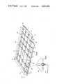
- FIG. 3is a twice sectioned (A--A and B--B of FIG. 1) perspective view of the keyboard of this invention equipped with an optical connection.
- FIG. 4is a perspective section (C--C of FIG. 1) of the keyboard of this invention.
- FIG. 5is a cross-sectional view (D--D of FIG. 4) illustrating a light source at a waveguide.
- FIG. 6is an exploded view of the key assembly and guide of the keyboard of this invention.
- FIG. 7is a schematic diagram illustrating the effect of four keys being depressed at the same time.
- FIG. 8is a cross-sectional view of four keys being depressed at the same time.
- computer 11 having display 12is connected electrically (or optically) through cord 13 to optionally activated keyboard 20.
- Computer 11 and display 12may be any of the personal computers available, such as the Professional Computer of Texas Instruments Incorporated.
- a personal computeris shown, but any terminal or other computer, with appropriate interfacing, could be connected to the manual input keyboard device 20 of this invention.
- FIG. 2is a top view of the optically activated keyboard 20 illustrating keyboard sections 21, 22, 23, 24, and 25. All of the keys are not shown for purposes for clarity. Electrical cord 13' is shown having connector 14. Connector 14 is an electrical connector for making electrical connections within the computer 11.
- FIG. 3illustrates optically activated keyboard 20' illustrating sections A--A and B--B.
- rubber dome 35is shown fitting over guide 37.
- Key cap 31fits over rubber dome 35 and plunger 32 (see FIG. 6) passes through dome 35 and guide 37 when key cap 31 is pressed.
- wave guide columns 40 and wave guide rows 41are shown. They are formed in housing 39.
- Cord 13contains optical fibers 42 that are connected to the columns and rows for transmitting light from the LED's and for transmitting light to the photo transistors.
- the LED's and the photo transistorsare housed in assembly 30 having electrical contacts 48 for connection to computer 11.
- the optical fibers 42 for transmitting light from the LED'sare shown connected to the columns 40 through a lens connection 45.
- the optical fibers for transmitting light from the photo transistorsare shown connected through lens 46 to the rows 41.
- section 19is shown without keys.
- that sectionis shown with a facility for adding keys.
- FIG. 4illustrates a section C--C in the housing 39 to more clearly illustrate the wave guide matrix made up of columns 40 and rows 41 formed in housing 39.
- housing 39is a plastic material in which the columns 40 and rows 41 have been formed in the molding procedure by which the housing 39 was made.
- the plastic materialis Polycarbonate with a refractive index of 1.5 microns at a wavelength of 0.651 microns. These columns and rows could also be formed by machining, such as milling, and then polishing.
- Guide 37is shown throught which the key plunger 32 (see FIG. 6) passes.
- the LED's 50 shown in place in columns 40are Texas Instruments Type TIL903-1.
- the photo transistors 51 shown in place in the rows 41are Texas Instruments Type TIL-414. Both the LED and photo transistor are arbitrary choices and many suitable substitutes may be found. In this particular embodiment, infrared light is employed, but visible light and higher frequency light could be employed as well.
- FIG. 5is a sectional view D--D taken as shown in FIG. 4 illustrating LED 50 positioned in recess 54 to enable light to pass into column 40, formed in housing 39. Electrical conductors 52 ultimately are packaged in cord 13' for electrical connection to the computer 11. FIGS. 4 and 5 would be virtually unchanged in the configuration where optical fibers are brought in and connected to the columns 40 and rows 41 form remote LED's and photo transistors.
- columns 40could have photo transistors 51 in place and rows 41 could have LED's 50 in place. That is to say, there can be a total reversal of the pattern of the preferred embodiment shown.
- FIG. 6illustrates key cap 31 which fits on plunger 32, plunger 32 passing through rubber dome 35 and guide 37 set in housing 39.
- a configuration of plunger 32fits into a corresponding configuration in guide 37 to prevent rotation of plunger 32.
- Column 40 and row 41are shown in housing 39.
- Reflective surface 33is shown formed in plunger 32 at an angle appropriate to reflect light from a column into a row. The angle depends on the material of which the plunger is made and the frequency of light. In this preferred embodiment, infrared light is employed and the angle is approximately 45 degrees. Rubber dome 35 provides resiliency so that when key cap 31 is released, dome 35 forces key cap 31 and plunger 32 back to the up position. A spring suitably positioned could also be used for this purpose.
- the plunger 32is made of Polycarbonate, the same material as housing 39. This material, properly dimensioned, permits light to pass through as well as to be reflected. This is an engineering design choice and other materials may be used as well.
- FIG. 7is a schematic diagram illustrating the emission of light from the emitters E1-E4 to the receivers R1-R3.
- Emitter E1in this preferred embodiment an LED is shown emitting light into column 140.
- the lightis reflected by a selected key which causes reflecting surface 133 to intrude into the light guide. Some of the light passes reflective surface 133 to reflective surface 134 from another key that has been depressed. Some of the light reflects from surface 134 and some of the light passes through.
- the light reflected from surface 133passes to reflective surface 135 from still another depressed key.
- the lightpasses reflective surface 135 and impinges against receiver R1 (photo transistors in this preferred embodiment).
- Light reflected by surface 134passes to reflective surface 136 from still another depressed button and continues to receiver R2.
- the keys for reflective surfaces 133 and 134are both detected at receivers R1 and R2.
- the first of the keys depressedprovides the first signal. When two or more keys are pressed at precisely the same moment, an arbitrary logic
- the keys with surfaces 135 and 136were also depressed. However, their associated emitter E2 has not been activated.
- the emittersare activated by scanning, as indicated earlier.
- the electronics of the Texas Instruments 940 terminal keyboardis used. More specifically, a Texas Instruments 3870 microcomputer performs the scanning. The microcomputer is connected to each of the LED's to sequentially activate them. This is a conventional scanning technique and need not be described in detail here.
- emitter E2is activated by the scanning procedure, then the keys corresponding to reflecting surfaces 135 and 136 are detected in a like manner. This facility for reflection and transmission overcome the "phantom key" or N-key roll-over keyboard problem where a depressed key "hides” another depressed key.
- FIG. 8is a cross-section of column 140 showing an emitter E5 in position with key caps 131-431 all depressed, causing plungers 132-432 to intrude into the light guide as indicated. Reflective surfaces 133-433 are shown for reflecting and passing light from emitter E5.
- lightis not only reflected, but passed by the material employed in plungers 132-432.
- the plungerscould extend to the bottom surface 141 of column 140.
- This configurationrequires material that not only reflects light into the appropriate row, but also permits light to pass in the column 140.
- the light wave column 140is approximately 0.190 inches in diameters, and plungers 132-432 are permitted to intrude a distance of approximately 0.06 inches, thereby leaving a distance of approximately 0.130 inches between surface 141 and the bottom of plungers 132-432.
- Such a structurepermits light to pass below the plungers as well as through the plungers, and also to be reflected by reflecting surfaces 133-433.
- Plungersmay be made of materials that do not pass light but are simply reflective. For example, in another embodiment, aluminum is used and reflective surfaces 133-433 are polished to a number 4L microfinish.
- the plungersmay be made of other opaque materials and appropriately reflective materials affixed to them to form the reflecting surfaces 133-433. However, when the plungers are designed to contact the bottom surface 141, then polarizing materials are required for reflection and a transmission of light.
- the wave guides forming the matrix in this inventionmay be formed of various types of light guiding materials.
- fiber opticsmay be employed in grooves to serve as the columns and rows. Grooves may be lined with appropriate material to form the light guide.
Landscapes
- Engineering & Computer Science (AREA)
- General Engineering & Computer Science (AREA)
- Theoretical Computer Science (AREA)
- Human Computer Interaction (AREA)
- Physics & Mathematics (AREA)
- General Physics & Mathematics (AREA)
- Push-Button Switches (AREA)
- Input From Keyboards Or The Like (AREA)
- Electronic Switches (AREA)
Abstract
Description
1. Field of the Invention
This invention relates to a manual input keyboard for digital systems. More specifically, it refers to digital systems having a manual input keyboard that is optically activated.
2. Description of the Prior Art
In the past, typical keyboards for use in digital systems have employed contact switches for making electrical circuits. The circuit continuity identifies a particular key that has been depressed. Reed switches have been employed and in more recent time, Hall Effect sensore have been employed.
Optical keyboards have been employed in the prior art. These prior art optical keyboards involve a plurality of columns, each having an LED at one end and a photo transistor at the other, and a plutality of intersecting rows, also with an LED and photo transistor at the ends. Keys are located at the intersections of these columns and rows and when a key is depressed, both the column and row light is interrupted and the appropriate photo transistors are turned off. In this manner, a depressed key is located.
Still another prior art optical keyboard involves less than a one for one relationship between light emitters and light detectors to reduce the number of components required.
In the present invention however, blocking light is not done. Instead, a reflection of light is employed to contact a photo transistor and thereby to increase its signal output.
This invention involves an optical keyboard with a wave guide matrix formed in its housing. A wave guide matrix is made up of columns and intersecting rows. In this preferred embodiment, LED's are positioned at one end of each of the columns. Photo transistors are positioned at one end of each of the rows. There is an aperture formed above each intersection in the housing surface. Key assemblies are positioned above the apertures, each key assembly having a plunger that passes through the aperture into the intersection of the wave guide column and row. A guide is set into the aperture and contoured to prevent rotation of the plunger.
The LED's are sequentially turned on and off by a scanning microprocessor. Since the identification of the activated LED is known and since the affected photo transistor is detected by a resultant signal, the depressed key is identifiable. The depressed key has a plunger which, in this preferred embodiment, intrudes into the wave guide intersection a limited distance. It has a reflective surface that is inclined at a desired angle to reflect light from the LED in its column to the photo transistor in its row. Additionally, light from its LED continues transmission through the column, below the plunger. If another plunger is depressed at the same time, the transmitted light is reflected from that plunger's reflecting surface to the appropriate photo transistor. The first key depressed is the first key read. Also, if a key has been depressed in its row, the reflected light continues transmission in the row. If the keys were depressed at precisely the same moment, the problem of which key should be recognized is logically accomplished.
In another embodiment of this invention, the LED's and photo transistors are located at the data handling apparatus such as a digital computer. They are then connected to the appropriate columns and rows through optical fibers, thereby providing a keyboard that is non-electronic.
The advantage of this keyboard over the prior art keyboards is that it is insensitive to electromagnetic and radio-frequency interference, eliminates combustion or sparks caused by short circuits or making and breaking of contacts, has low transmission loss and wide transmission bandwidth. It is advantageous over any prior art optical systems because of its simplicity of design and resultant low cost and reliability.
The principal object of this invention is to provide a digital system having an input keyboard that is simple in structure and insensitive to electromagnetic and radio-frequency interference.
Another object of this invention is to provide a keyboard that requires no electrical input and therefore may be isolated in a hostile environment.
Still another object of this invention is to provide a keyboard that has low transmission loss and wide transmission bandwith. These and other objects will be made evident in the detailed description that follows.
FIG. 1 is a perspective view of the digital system of this invention.
FIG. 2 is a top view of the optical keyboard device of this invention equipped with an electrical cord connection.
FIG. 3 is a twice sectioned (A--A and B--B of FIG. 1) perspective view of the keyboard of this invention equipped with an optical connection.
FIG. 4 is a perspective section (C--C of FIG. 1) of the keyboard of this invention.
FIG. 5 is a cross-sectional view (D--D of FIG. 4) illustrating a light source at a waveguide.
FIG. 6 is an exploded view of the key assembly and guide of the keyboard of this invention.
FIG. 7 is a schematic diagram illustrating the effect of four keys being depressed at the same time.
FIG. 8 is a cross-sectional view of four keys being depressed at the same time.
In FIG. 1, computer 11 havingdisplay 12 is connected electrically (or optically) throughcord 13 to optionally activatedkeyboard 20. Computer 11 anddisplay 12 may be any of the personal computers available, such as the Professional Computer of Texas Instruments Incorporated. A personal computer is shown, but any terminal or other computer, with appropriate interfacing, could be connected to the manualinput keyboard device 20 of this invention.
FIG. 2 is a top view of the optically activatedkeyboard 20 illustratingkeyboard sections
FIG. 3 illustrates optically activated keyboard 20' illustrating sections A--A and B--B. In section A--A,rubber dome 35 is shown fitting overguide 37. Key cap 31 fits overrubber dome 35 and plunger 32 (see FIG. 6) passes throughdome 35 and guide 37 when key cap 31 is pressed.
In section B--B,wave guide columns 40 andwave guide rows 41 are shown. They are formed inhousing 39.Cord 13", containsoptical fibers 42 that are connected to the columns and rows for transmitting light from the LED's and for transmitting light to the photo transistors. The LED's and the photo transistors are housed inassembly 30 havingelectrical contacts 48 for connection to computer 11.
Theoptical fibers 42 for transmitting light from the LED's are shown connected to thecolumns 40 through alens connection 45. The optical fibers for transmitting light from the photo transistors are shown connected throughlens 46 to therows 41. In FIG. 1,section 19 is shown without keys. In FIG. 3, that section is shown with a facility for adding keys.
FIG. 4 illustrates a section C--C in thehousing 39 to more clearly illustrate the wave guide matrix made up ofcolumns 40 androws 41 formed inhousing 39. In this preferred embodiment,housing 39 is a plastic material in which thecolumns 40 androws 41 have been formed in the molding procedure by which thehousing 39 was made. In this preferred embodiment, the plastic material is Polycarbonate with a refractive index of 1.5 microns at a wavelength of 0.651 microns. These columns and rows could also be formed by machining, such as milling, and then polishing.Guide 37 is shown throught which the key plunger 32 (see FIG. 6) passes. In this preferred embodiment, the LED's 50 shown in place incolumns 40, are Texas Instruments Type TIL903-1. Thephoto transistors 51 shown in place in therows 41 are Texas Instruments Type TIL-414. Both the LED and photo transistor are arbitrary choices and many suitable substitutes may be found. In this particular embodiment, infrared light is employed, but visible light and higher frequency light could be employed as well.
FIG. 5 is a sectional view D--D taken as shown in FIG. 4illustrating LED 50 positioned inrecess 54 to enable light to pass intocolumn 40, formed inhousing 39.Electrical conductors 52 ultimately are packaged in cord 13' for electrical connection to the computer 11. FIGS. 4 and 5 would be virtually unchanged in the configuration where optical fibers are brought in and connected to thecolumns 40 androws 41 form remote LED's and photo transistors.
It should be noted thatcolumns 40 could havephoto transistors 51 in place androws 41 could have LED's 50 in place. That is to say, there can be a total reversal of the pattern of the preferred embodiment shown.
FIG. 6 illustrates key cap 31 which fits onplunger 32,plunger 32 passing throughrubber dome 35 and guide 37 set inhousing 39. A configuration ofplunger 32 fits into a corresponding configuration inguide 37 to prevent rotation ofplunger 32.Column 40 androw 41 are shown inhousing 39.
Reflective surface 33 is shown formed inplunger 32 at an angle appropriate to reflect light from a column into a row. The angle depends on the material of which the plunger is made and the frequency of light. In this preferred embodiment, infrared light is employed and the angle is approximately 45 degrees.Rubber dome 35 provides resiliency so that when key cap 31 is released,dome 35 forces key cap 31 andplunger 32 back to the up position. A spring suitably positioned could also be used for this purpose.
In the preferred embodiment, theplunger 32 is made of Polycarbonate, the same material ashousing 39. This material, properly dimensioned, permits light to pass through as well as to be reflected. This is an engineering design choice and other materials may be used as well.
FIG. 7 is a schematic diagram illustrating the emission of light from the emitters E1-E4 to the receivers R1-R3. Emitter E1 (in this preferred embodiment an LED) is shown emitting light intocolumn 140. The light is reflected by a selected key which causes reflectingsurface 133 to intrude into the light guide. Some of the light passesreflective surface 133 toreflective surface 134 from another key that has been depressed. Some of the light reflects fromsurface 134 and some of the light passes through. The light reflected fromsurface 133 passes toreflective surface 135 from still another depressed key. The light passesreflective surface 135 and impinges against receiver R1 (photo transistors in this preferred embodiment). Light reflected bysurface 134 passes toreflective surface 136 from still another depressed button and continues to receiver R2. In this example, the keys forreflective surfaces
The keys withsurfaces surfaces
FIG. 8 is a cross-section ofcolumn 140 showing an emitter E5 in position with key caps 131-431 all depressed, causing plungers 132-432 to intrude into the light guide as indicated. Reflective surfaces 133-433 are shown for reflecting and passing light from emitter E5.
As indicated, in this preferred embodiment, light is not only reflected, but passed by the material employed in plungers 132-432. With the proper selection of materials, the plungers could extend to thebottom surface 141 ofcolumn 140. This configuration requires material that not only reflects light into the appropriate row, but also permits light to pass in thecolumn 140. In this preferred embodiment, however, thelight wave column 140 is approximately 0.190 inches in diameters, and plungers 132-432 are permitted to intrude a distance of approximately 0.06 inches, thereby leaving a distance of approximately 0.130 inches betweensurface 141 and the bottom of plungers 132-432. Such a structure permits light to pass below the plungers as well as through the plungers, and also to be reflected by reflecting surfaces 133-433.
Plungers may be made of materials that do not pass light but are simply reflective. For example, in another embodiment, aluminum is used and reflective surfaces 133-433 are polished to a number 4L microfinish.
The plungers may be made of other opaque materials and appropriately reflective materials affixed to them to form the reflecting surfaces 133-433. However, when the plungers are designed to contact thebottom surface 141, then polarizing materials are required for reflection and a transmission of light.
It is contemplated that other light sources and LED's may be employed in this invention. For example, it is certainly contemplated that a laser could be employed. Also, various types of photo detectors are contemplated other than photo transistors. The wave guides forming the matrix in this invention may be formed of various types of light guiding materials. For example, fiber optics may be employed in grooves to serve as the columns and rows. Grooves may be lined with appropriate material to form the light guide. These and other changes are obvious and this invention is limited only by the scope of the appended claims.
Claims (13)
1. Manual input apparatus having scanning means, for providing inputs to data handling apparatus, comprising:
(a) key housing means having a matrix of apertures formed through the top surface thereof;
(b) wave guide means formed in the key housing means in a matrix configuration of columns and rows with the intersections of the columns and rows aligned below the apertures;
(c) light source means connected to each column, each light source means being turned on and off in a predetermined order by the scanning means;
(d) light detecting means connected to each row, activated by impinging light to provide a signal indicative of detection;
(e) key means resiliently mounted over each aperture and having a plunger for passing through the aperture when a key means is selected and depressed; and
(f) polarizing means formed by each plunger to reflect light, from a light source means that is turned on at a scanned column when the key means has been depressed, through the row at that intersection to the light detecting means associated with that row wherein each plunger is dimensioned so that when the associated key means is depressed, the plunger intrudes into the wave guide means a predetermined distance, defining a volume between the bottom of each plunger and the bottom of the wave guide means to permit light to pass through the volume in the scanned column to allow detection of other depressed keys in the scanned column and associated rows.
2. The apparatus of claim 1 further comprising optical fiber means for connecting each light source means to each column and for connecting each light detecting means to each row.
3. The apparatus of claim 1 wherein each plunger has a reflecting surface formed at a desired angle to the rows and columns to reflect light into the row at the intersection of a depressed key means.
4. The apparatus of claim 2 wherein each plunger has a reflecting surface formed at a desired angle to the rows and columns to reflect light into the row at the intersection of a depressed key means.
5. The apparatus of claim 3 wherein the light source means comprises a light emitting diode for each column and the light detecting means comprises a photo transistor for each row.
6. The apparatus of claim 4 wherein the light source means comprises a light emitting diode for each column and the light detecting means comprises a photo transistor for each row.
7. Digital apparatus comprising:
(a) data handling means; and
(b) manual input means operatively connected to supply input signals to the data handling means, the manual input means comprising:
key housing means having a matrix of apertures formed through the top surface thereof,
wave guide means formed in the key housing means in a matrix configuration of columns and rows with the intersections of the columns and rows aligned below the apertures,
light source means connected to each column, each light source means being turned on and off in a predetermined order by the scanning means,
light detecting means connected to each row, activated by impinging light to provide a signal indicative of detection;
key means resiliently mounted over each aperture and each key means having a plunger for passing through the aperture when a key means is selected and depressed, and
polarizing means formed by each plunger to reflect light, from a light source means that is turned on at a scanned column when the key means has been depressed, through the row at that intersection to the light detecting means associated with that row wherein each plunger is dimensioned so that when the associated key means is depressed, the plunger intrudes into the wave guide means a predetermined distance, defining a volume between the bottom of each plunger and the bottom of the wave guide means to permit light to pass through the volume in the scanned column to allow detection of other depressed keys in the scanned column and associated rows.
8. The apparatus of claim 7 further comprising optical fiber means for connecting each light source means to each column and for connecting each light detecting means to each row.
9. The apparatus of claim 7 wherein each plunger has a reflecting surface formed at a desired angle to the rows and columns to reflect light into the row at the intersection of a depressed key means.
10. The apparatus of claim 8 wherein each plunger has a reflecting surface formed at a desired angle to the rows and columns to reflect light into the row at the intersection of a depressed key means.
11. The apparatus of claim 9 wherein the light source means comprises a light emitting diode for each column and the light detecting means comprises a photo transistor for each row.
12. The apparatus of claim 10 wherein the light source means comprises a light emitting diode for each column and a light detecting means comprises a photo transistor for each row.
13. The apparatus of claim 7 wherein the data handling means comprises a digital computer.
Priority Applications (5)
| Application Number | Priority Date | Filing Date | Title |
|---|---|---|---|
| US06/576,225US4641026A (en) | 1984-02-02 | 1984-02-02 | Optically activated keyboard for digital system |
| EP85300579AEP0151022B1 (en) | 1984-02-02 | 1985-01-29 | Manual input apparatus for providing inputs to data handling apparatus |
| DE8585300579TDE3579469D1 (en) | 1984-02-02 | 1985-01-29 | MANUAL INPUT DEVICE FOR DELIVERING INPUT TO A DATA PROCESSING DEVICE. |
| JP60018477AJPS60236414A (en) | 1984-02-02 | 1985-02-01 | Manual input unit of digital system |
| US07/308,696USRE33422E (en) | 1984-02-02 | 1989-02-03 | Optically activated keyboard for digital system |
Applications Claiming Priority (1)
| Application Number | Priority Date | Filing Date | Title |
|---|---|---|---|
| US06/576,225US4641026A (en) | 1984-02-02 | 1984-02-02 | Optically activated keyboard for digital system |
Related Child Applications (1)
| Application Number | Title | Priority Date | Filing Date |
|---|---|---|---|
| US07/308,696ReissueUSRE33422E (en) | 1984-02-02 | 1989-02-03 | Optically activated keyboard for digital system |
Publications (1)
| Publication Number | Publication Date |
|---|---|
| US4641026Atrue US4641026A (en) | 1987-02-03 |
Family
ID=24303470
Family Applications (1)
| Application Number | Title | Priority Date | Filing Date |
|---|---|---|---|
| US06/576,225CeasedUS4641026A (en) | 1984-02-02 | 1984-02-02 | Optically activated keyboard for digital system |
Country Status (4)
| Country | Link |
|---|---|
| US (1) | US4641026A (en) |
| EP (1) | EP0151022B1 (en) |
| JP (1) | JPS60236414A (en) |
| DE (1) | DE3579469D1 (en) |
Cited By (68)
| Publication number | Priority date | Publication date | Assignee | Title |
|---|---|---|---|---|
| US4733068A (en)* | 1986-04-07 | 1988-03-22 | Rockwell International Corporation | Crossed fiber optic tactile sensor |
| US4831359A (en)* | 1988-01-13 | 1989-05-16 | Micro Research, Inc. | Four quadrant touch pad |
| US4847508A (en)* | 1986-03-27 | 1989-07-11 | Sadao Kokubu | Photo-coupler switch with delay function using a fluorescent substance as the delay means |
| US4860008A (en)* | 1986-04-22 | 1989-08-22 | Claude Battarel | Radiation interruption keyboard |
| US4868568A (en)* | 1986-03-19 | 1989-09-19 | Alain Souloumiac | Mirror optical keyboards |
| US4878722A (en)* | 1988-06-24 | 1989-11-07 | Korry Electronics Company | Wavelength encoded optical switches |
| US4980685A (en)* | 1986-02-24 | 1990-12-25 | Alain Souloumiac | Scanning optical keyboard |
| USD316543S (en) | 1988-05-31 | 1991-04-30 | Texas Instruments Incorporated | Portable computer |
| US5272383A (en)* | 1989-04-21 | 1993-12-21 | Shinkoh Electric Co., Ltd. | Method and apparatus for preventing erroneous operation in non-contact push-button switch |
| US5384459A (en)* | 1993-06-01 | 1995-01-24 | Motorola, Inc. | Illuminated switch and keypad assembly having a light gradient and a light conductive elastomeric assembly |
| US5477223A (en)* | 1992-08-12 | 1995-12-19 | Destremps; Gerald | Finger activated keyboard for a computer |
| US6031469A (en)* | 1996-11-12 | 2000-02-29 | Dodd; Jerry | Ergonomic computer keyboard |
| US6157026A (en)* | 1998-11-19 | 2000-12-05 | Maxtec International Corporation | Optical switch of the multiple push button type for producing a plurality of control signals |
| US6175679B1 (en)* | 1999-07-02 | 2001-01-16 | Brookhaven Science Associates | Optical keyboard |
| US6181847B1 (en) | 1999-05-10 | 2001-01-30 | Ametek, Inc. | Optical switch |
| US6201905B1 (en) | 1999-02-05 | 2001-03-13 | Telemotive Industrial Controls | Optical switch with controlled voltage output |
| WO2001026226A1 (en)* | 1999-10-06 | 2001-04-12 | Microsoft Corporation | Keypad having optical waveguides |
| US6369800B1 (en)* | 1998-04-03 | 2002-04-09 | Ericsson Inc. | Method and apparatus for use with a keypad of an electronic device |
| US6525677B1 (en)* | 2000-08-28 | 2003-02-25 | Motorola, Inc. | Method and apparatus for an optical laser keypad |
| US20040136637A1 (en)* | 2001-05-23 | 2004-07-15 | Verweg Franciscus Gerardus Coe | Sensor,display device and recording device |
| US20050184885A1 (en)* | 2004-02-24 | 2005-08-25 | Nokia Corporation | Optical keyboard with geodesic optical elements |
| US20060066576A1 (en)* | 2004-09-30 | 2006-03-30 | Microsoft Corporation | Keyboard or other input device using ranging for detection of control piece movement |
| US20060213997A1 (en)* | 2005-03-23 | 2006-09-28 | Microsoft Corporation | Method and apparatus for a cursor control device barcode reader |
| US20070002013A1 (en)* | 2005-06-30 | 2007-01-04 | Microsoft Corporation | Input device using laser self-mixing velocimeter |
| US20070102523A1 (en)* | 2005-11-08 | 2007-05-10 | Microsoft Corporation | Laser velocimetric image scanning |
| US20070109152A1 (en)* | 2005-11-14 | 2007-05-17 | Wald Steven F | Method and apparatus for optically detecting selections made on an input device |
| US20070109267A1 (en)* | 2005-11-14 | 2007-05-17 | Microsoft Corporation | Speckle-based two-dimensional motion tracking |
| US7505033B2 (en) | 2005-11-14 | 2009-03-17 | Microsoft Corporation | Speckle-based two-dimensional motion tracking |
| US20090236499A1 (en)* | 2008-03-24 | 2009-09-24 | Kyocera Corporation | Key Device and Electronic Device Comprising the Same |
| EP2088499A4 (en)* | 2006-11-30 | 2011-11-30 | Sega Corp | Position inputting apparatus |
| US20120139843A1 (en)* | 1999-09-15 | 2012-06-07 | Michael Shipman | Illuminated keyboard |
| US20120182215A1 (en)* | 2011-01-18 | 2012-07-19 | Samsung Electronics Co., Ltd. | Sensing module, and graphical user interface (gui) control apparatus and method |
| US20160306437A1 (en)* | 2015-04-15 | 2016-10-20 | Apple Inc. | Depressible Keys with Decoupled Electrical and Mechanical Functionality |
| CN106909229A (en)* | 2017-02-24 | 2017-06-30 | 广州幻境科技有限公司 | A kind of distribution type fiber-optic keyboard and its key detecting method |
| US9709956B1 (en) | 2013-08-09 | 2017-07-18 | Apple Inc. | Tactile switch for an electronic device |
| US9753436B2 (en) | 2013-06-11 | 2017-09-05 | Apple Inc. | Rotary input mechanism for an electronic device |
| US20170278499A1 (en)* | 2014-08-23 | 2017-09-28 | Moon Key Lee | Row division optical module and electronic keyboard using same |
| US9797752B1 (en) | 2014-07-16 | 2017-10-24 | Apple Inc. | Optical encoder with axially aligned sensor |
| US9797753B1 (en) | 2014-08-27 | 2017-10-24 | Apple Inc. | Spatial phase estimation for optical encoders |
| US9857892B2 (en) | 2012-09-13 | 2018-01-02 | Apple Inc. | Optical sensing mechanisms for input devices |
| US9891651B2 (en) | 2016-02-27 | 2018-02-13 | Apple Inc. | Rotatable input mechanism having adjustable output |
| US9952558B2 (en) | 2015-03-08 | 2018-04-24 | Apple Inc. | Compressible seal for rotatable and translatable input mechanisms |
| US10018966B2 (en) | 2015-04-24 | 2018-07-10 | Apple Inc. | Cover member for an input mechanism of an electronic device |
| US10019097B2 (en) | 2016-07-25 | 2018-07-10 | Apple Inc. | Force-detecting input structure |
| US10048802B2 (en) | 2014-02-12 | 2018-08-14 | Apple Inc. | Rejection of false turns of rotary inputs for electronic devices |
| US10061399B2 (en) | 2016-07-15 | 2018-08-28 | Apple Inc. | Capacitive gap sensor ring for an input device |
| US10066970B2 (en) | 2014-08-27 | 2018-09-04 | Apple Inc. | Dynamic range control for optical encoders |
| US10145711B2 (en) | 2015-03-05 | 2018-12-04 | Apple Inc. | Optical encoder with direction-dependent optical properties having an optically anisotropic region to produce a first and a second light distribution |
| US10190891B1 (en) | 2014-07-16 | 2019-01-29 | Apple Inc. | Optical encoder for detecting rotational and axial movement |
| US10379578B2 (en)* | 2015-07-27 | 2019-08-13 | Samsung Display Co., Ltd. | Flexible display device and driving method thereof |
| US10551798B1 (en) | 2016-05-17 | 2020-02-04 | Apple Inc. | Rotatable crown for an electronic device |
| US10599101B2 (en) | 2014-09-02 | 2020-03-24 | Apple Inc. | Wearable electronic device |
| US10664074B2 (en) | 2017-06-19 | 2020-05-26 | Apple Inc. | Contact-sensitive crown for an electronic watch |
| US10935420B2 (en) | 2015-08-13 | 2021-03-02 | Texas Instruments Incorporated | Optical interface for data transmission |
| US10962935B1 (en) | 2017-07-18 | 2021-03-30 | Apple Inc. | Tri-axis force sensor |
| US11181863B2 (en) | 2018-08-24 | 2021-11-23 | Apple Inc. | Conductive cap for watch crown |
| US11194298B2 (en) | 2018-08-30 | 2021-12-07 | Apple Inc. | Crown assembly for an electronic watch |
| US11194299B1 (en) | 2019-02-12 | 2021-12-07 | Apple Inc. | Variable frictional feedback device for a digital crown of an electronic watch |
| US11269376B2 (en) | 2020-06-11 | 2022-03-08 | Apple Inc. | Electronic device |
| US11360440B2 (en) | 2018-06-25 | 2022-06-14 | Apple Inc. | Crown for an electronic watch |
| US11550268B2 (en) | 2020-06-02 | 2023-01-10 | Apple Inc. | Switch module for electronic crown assembly |
| US11561515B2 (en) | 2018-08-02 | 2023-01-24 | Apple Inc. | Crown for an electronic watch |
| US11796968B2 (en) | 2018-08-30 | 2023-10-24 | Apple Inc. | Crown assembly for an electronic watch |
| US11796961B2 (en) | 2018-08-24 | 2023-10-24 | Apple Inc. | Conductive cap for watch crown |
| US12092996B2 (en) | 2021-07-16 | 2024-09-17 | Apple Inc. | Laser-based rotation sensor for a crown of an electronic watch |
| US12189347B2 (en) | 2022-06-14 | 2025-01-07 | Apple Inc. | Rotation sensor for a crown of an electronic watch |
| US12259690B2 (en) | 2018-08-24 | 2025-03-25 | Apple Inc. | Watch crown having a conductive surface |
| US20250138648A1 (en)* | 2023-10-31 | 2025-05-01 | Dell Products, Lp | System and method for a quiet keyboard with optical matrix key positioning |
Families Citing this family (4)
| Publication number | Priority date | Publication date | Assignee | Title |
|---|---|---|---|---|
| WO1987002529A1 (en)* | 1985-10-18 | 1987-04-23 | Radice Peter F | Pyroelectric keyboard |
| DE3700856A1 (en)* | 1987-01-14 | 1988-07-28 | Telefunken Electronic Gmbh | OPTOELECTRONIC KEYBOARD |
| JP2504894B2 (en)* | 1992-06-27 | 1996-06-05 | フジミ光機株式会社 | KEYBOARD KEY DECODING METHOD AND KEYBOARD KEY DETERMINING DEVICE |
| GB2406944A (en)* | 2003-10-09 | 2005-04-13 | Motorola Inc | Keyboard switching devices |
Citations (6)
| Publication number | Priority date | Publication date | Assignee | Title |
|---|---|---|---|---|
| US3603982A (en)* | 1969-05-02 | 1971-09-07 | Ncr Co | Data entry means |
| US3648050A (en)* | 1970-08-06 | 1972-03-07 | Tuh Kai Koo | Optoelectronic data entry means having plurality of control means to direct part of radiation in channel from radiation source to output channel |
| US3856127A (en)* | 1972-11-24 | 1974-12-24 | U Halfon | Photo-optical keyboard |
| EP0004520A1 (en)* | 1978-03-24 | 1979-10-03 | International Business Machines Corporation | Keyboard with an array of light beam splitters |
| US4379968A (en)* | 1980-12-24 | 1983-04-12 | Burroughs Corp. | Photo-optical keyboard having light attenuating means |
| US4442425A (en)* | 1981-11-13 | 1984-04-10 | Sperry Corporation | Passive fiber optic keyboard |
Family Cites Families (2)
| Publication number | Priority date | Publication date | Assignee | Title |
|---|---|---|---|---|
| US3847262A (en)* | 1969-03-14 | 1974-11-12 | Datacq Syst Corp | Apparatus and attachment for deriving coded signals |
| DE2339453A1 (en)* | 1973-04-18 | 1974-11-07 | Marconi Co Ltd | DEVICE FOR ENCODING POSITIONS |
- 1984
- 1984-02-02USUS06/576,225patent/US4641026A/ennot_activeCeased
- 1985
- 1985-01-29DEDE8585300579Tpatent/DE3579469D1/ennot_activeExpired - Lifetime
- 1985-01-29EPEP85300579Apatent/EP0151022B1/ennot_activeExpired
- 1985-02-01JPJP60018477Apatent/JPS60236414A/enactiveGranted
Patent Citations (6)
| Publication number | Priority date | Publication date | Assignee | Title |
|---|---|---|---|---|
| US3603982A (en)* | 1969-05-02 | 1971-09-07 | Ncr Co | Data entry means |
| US3648050A (en)* | 1970-08-06 | 1972-03-07 | Tuh Kai Koo | Optoelectronic data entry means having plurality of control means to direct part of radiation in channel from radiation source to output channel |
| US3856127A (en)* | 1972-11-24 | 1974-12-24 | U Halfon | Photo-optical keyboard |
| EP0004520A1 (en)* | 1978-03-24 | 1979-10-03 | International Business Machines Corporation | Keyboard with an array of light beam splitters |
| US4379968A (en)* | 1980-12-24 | 1983-04-12 | Burroughs Corp. | Photo-optical keyboard having light attenuating means |
| US4442425A (en)* | 1981-11-13 | 1984-04-10 | Sperry Corporation | Passive fiber optic keyboard |
Cited By (144)
| Publication number | Priority date | Publication date | Assignee | Title |
|---|---|---|---|---|
| US4980685A (en)* | 1986-02-24 | 1990-12-25 | Alain Souloumiac | Scanning optical keyboard |
| US4868568A (en)* | 1986-03-19 | 1989-09-19 | Alain Souloumiac | Mirror optical keyboards |
| US4847508A (en)* | 1986-03-27 | 1989-07-11 | Sadao Kokubu | Photo-coupler switch with delay function using a fluorescent substance as the delay means |
| US4733068A (en)* | 1986-04-07 | 1988-03-22 | Rockwell International Corporation | Crossed fiber optic tactile sensor |
| US4860008A (en)* | 1986-04-22 | 1989-08-22 | Claude Battarel | Radiation interruption keyboard |
| US4831359A (en)* | 1988-01-13 | 1989-05-16 | Micro Research, Inc. | Four quadrant touch pad |
| USD316543S (en) | 1988-05-31 | 1991-04-30 | Texas Instruments Incorporated | Portable computer |
| US4878722A (en)* | 1988-06-24 | 1989-11-07 | Korry Electronics Company | Wavelength encoded optical switches |
| US5272383A (en)* | 1989-04-21 | 1993-12-21 | Shinkoh Electric Co., Ltd. | Method and apparatus for preventing erroneous operation in non-contact push-button switch |
| US5321311A (en)* | 1989-04-21 | 1994-06-14 | Shinkoh Electric Co., Ltd. | Apparatus for detecting erroneous operation in a non-contact push-button switch |
| US5477223A (en)* | 1992-08-12 | 1995-12-19 | Destremps; Gerald | Finger activated keyboard for a computer |
| US5384459A (en)* | 1993-06-01 | 1995-01-24 | Motorola, Inc. | Illuminated switch and keypad assembly having a light gradient and a light conductive elastomeric assembly |
| US6031469A (en)* | 1996-11-12 | 2000-02-29 | Dodd; Jerry | Ergonomic computer keyboard |
| US6369800B1 (en)* | 1998-04-03 | 2002-04-09 | Ericsson Inc. | Method and apparatus for use with a keypad of an electronic device |
| US6157026A (en)* | 1998-11-19 | 2000-12-05 | Maxtec International Corporation | Optical switch of the multiple push button type for producing a plurality of control signals |
| US6201905B1 (en) | 1999-02-05 | 2001-03-13 | Telemotive Industrial Controls | Optical switch with controlled voltage output |
| US6181847B1 (en) | 1999-05-10 | 2001-01-30 | Ametek, Inc. | Optical switch |
| US6175679B1 (en)* | 1999-07-02 | 2001-01-16 | Brookhaven Science Associates | Optical keyboard |
| US20120139843A1 (en)* | 1999-09-15 | 2012-06-07 | Michael Shipman | Illuminated keyboard |
| US8890720B2 (en)* | 1999-09-15 | 2014-11-18 | Michael Shipman | Illuminated keyboard |
| WO2001026226A1 (en)* | 1999-10-06 | 2001-04-12 | Microsoft Corporation | Keypad having optical waveguides |
| US6741189B1 (en) | 1999-10-06 | 2004-05-25 | Microsoft Corporation | Keypad having optical waveguides |
| US6525677B1 (en)* | 2000-08-28 | 2003-02-25 | Motorola, Inc. | Method and apparatus for an optical laser keypad |
| US20040136637A1 (en)* | 2001-05-23 | 2004-07-15 | Verweg Franciscus Gerardus Coe | Sensor,display device and recording device |
| US20050184885A1 (en)* | 2004-02-24 | 2005-08-25 | Nokia Corporation | Optical keyboard with geodesic optical elements |
| US7042371B2 (en)* | 2004-02-24 | 2006-05-09 | Nokia Corporation | Optical keyboard with geodesic optical elements |
| US20060066576A1 (en)* | 2004-09-30 | 2006-03-30 | Microsoft Corporation | Keyboard or other input device using ranging for detection of control piece movement |
| US7528824B2 (en)* | 2004-09-30 | 2009-05-05 | Microsoft Corporation | Keyboard or other input device using ranging for detection of control piece movement |
| US20060213997A1 (en)* | 2005-03-23 | 2006-09-28 | Microsoft Corporation | Method and apparatus for a cursor control device barcode reader |
| US20070002013A1 (en)* | 2005-06-30 | 2007-01-04 | Microsoft Corporation | Input device using laser self-mixing velocimeter |
| US7557795B2 (en) | 2005-06-30 | 2009-07-07 | Microsoft Corporation | Input device using laser self-mixing velocimeter |
| US7543750B2 (en) | 2005-11-08 | 2009-06-09 | Microsoft Corporation | Laser velocimetric image scanning |
| US20070102523A1 (en)* | 2005-11-08 | 2007-05-10 | Microsoft Corporation | Laser velocimetric image scanning |
| US7446677B2 (en)* | 2005-11-14 | 2008-11-04 | Avago Technologies Ecbu Ip Pte Ltd | Method and apparatus for optically detecting selections made on an input device |
| US20070109267A1 (en)* | 2005-11-14 | 2007-05-17 | Microsoft Corporation | Speckle-based two-dimensional motion tracking |
| US20070109152A1 (en)* | 2005-11-14 | 2007-05-17 | Wald Steven F | Method and apparatus for optically detecting selections made on an input device |
| US7505033B2 (en) | 2005-11-14 | 2009-03-17 | Microsoft Corporation | Speckle-based two-dimensional motion tracking |
| EP2088499A4 (en)* | 2006-11-30 | 2011-11-30 | Sega Corp | Position inputting apparatus |
| US8124926B2 (en)* | 2008-03-24 | 2012-02-28 | Kyocera Corporation | Key device and electronic device comprising the same |
| US20090236499A1 (en)* | 2008-03-24 | 2009-09-24 | Kyocera Corporation | Key Device and Electronic Device Comprising the Same |
| US20120182215A1 (en)* | 2011-01-18 | 2012-07-19 | Samsung Electronics Co., Ltd. | Sensing module, and graphical user interface (gui) control apparatus and method |
| US9733711B2 (en)* | 2011-01-18 | 2017-08-15 | Samsung Electronics Co., Ltd. | Sensing module, and graphical user interface (GUI) control apparatus and method |
| US9857892B2 (en) | 2012-09-13 | 2018-01-02 | Apple Inc. | Optical sensing mechanisms for input devices |
| US11531306B2 (en) | 2013-06-11 | 2022-12-20 | Apple Inc. | Rotary input mechanism for an electronic device |
| US10234828B2 (en) | 2013-06-11 | 2019-03-19 | Apple Inc. | Rotary input mechanism for an electronic device |
| US9753436B2 (en) | 2013-06-11 | 2017-09-05 | Apple Inc. | Rotary input mechanism for an electronic device |
| US9886006B2 (en) | 2013-06-11 | 2018-02-06 | Apple Inc. | Rotary input mechanism for an electronic device |
| US10331081B2 (en) | 2013-08-09 | 2019-06-25 | Apple Inc. | Tactile switch for an electronic device |
| US12181840B2 (en) | 2013-08-09 | 2024-12-31 | Apple Inc. | Tactile switch for an electronic device |
| US9836025B2 (en) | 2013-08-09 | 2017-12-05 | Apple Inc. | Tactile switch for an electronic device |
| US10331082B2 (en) | 2013-08-09 | 2019-06-25 | Apple Inc. | Tactile switch for an electronic device |
| US11886149B2 (en) | 2013-08-09 | 2024-01-30 | Apple Inc. | Tactile switch for an electronic device |
| US9709956B1 (en) | 2013-08-09 | 2017-07-18 | Apple Inc. | Tactile switch for an electronic device |
| US10216147B2 (en) | 2013-08-09 | 2019-02-26 | Apple Inc. | Tactile switch for an electronic device |
| US10962930B2 (en) | 2013-08-09 | 2021-03-30 | Apple Inc. | Tactile switch for an electronic device |
| US9971305B2 (en) | 2013-08-09 | 2018-05-15 | Apple Inc. | Tactile switch for an electronic device |
| US10175652B2 (en) | 2013-08-09 | 2019-01-08 | Apple Inc. | Tactile switch for an electronic device |
| US10732571B2 (en) | 2013-08-09 | 2020-08-04 | Apple Inc. | Tactile switch for an electronic device |
| US10884549B2 (en) | 2014-02-12 | 2021-01-05 | Apple Inc. | Rejection of false turns of rotary inputs for electronic devices |
| US10048802B2 (en) | 2014-02-12 | 2018-08-14 | Apple Inc. | Rejection of false turns of rotary inputs for electronic devices |
| US12045416B2 (en) | 2014-02-12 | 2024-07-23 | Apple Inc. | Rejection of false turns of rotary inputs for electronic devices |
| US11347351B2 (en) | 2014-02-12 | 2022-05-31 | Apple Inc. | Rejection of false turns of rotary inputs for electronic devices |
| US12307047B2 (en) | 2014-02-12 | 2025-05-20 | Apple Inc. | Rejection of false turns of rotary inputs for electronic devices |
| US11669205B2 (en) | 2014-02-12 | 2023-06-06 | Apple Inc. | Rejection of false turns of rotary inputs for electronic devices |
| US10613685B2 (en) | 2014-02-12 | 2020-04-07 | Apple Inc. | Rejection of false turns of rotary inputs for electronic devices |
| US10222909B2 (en) | 2014-02-12 | 2019-03-05 | Apple Inc. | Rejection of false turns of rotary inputs for electronic devices |
| US11015960B2 (en) | 2014-07-16 | 2021-05-25 | Apple Inc. | Optical encoder for detecting crown movement |
| US10190891B1 (en) | 2014-07-16 | 2019-01-29 | Apple Inc. | Optical encoder for detecting rotational and axial movement |
| US9797752B1 (en) | 2014-07-16 | 2017-10-24 | Apple Inc. | Optical encoder with axially aligned sensor |
| US10533879B2 (en) | 2014-07-16 | 2020-01-14 | Apple Inc. | Optical encoder with axially aligned sensor |
| US10199025B2 (en)* | 2014-08-23 | 2019-02-05 | Moon Key Lee | Image capturing device and electronic keyboard using the image capturing device |
| US20170278499A1 (en)* | 2014-08-23 | 2017-09-28 | Moon Key Lee | Row division optical module and electronic keyboard using same |
| US10066970B2 (en) | 2014-08-27 | 2018-09-04 | Apple Inc. | Dynamic range control for optical encoders |
| US9797753B1 (en) | 2014-08-27 | 2017-10-24 | Apple Inc. | Spatial phase estimation for optical encoders |
| US11762342B2 (en) | 2014-09-02 | 2023-09-19 | Apple Inc. | Wearable electronic device |
| US10620591B2 (en) | 2014-09-02 | 2020-04-14 | Apple Inc. | Wearable electronic device |
| US11474483B2 (en) | 2014-09-02 | 2022-10-18 | Apple Inc. | Wearable electronic device |
| US11567457B2 (en) | 2014-09-02 | 2023-01-31 | Apple Inc. | Wearable electronic device |
| US10942491B2 (en) | 2014-09-02 | 2021-03-09 | Apple Inc. | Wearable electronic device |
| US11221590B2 (en) | 2014-09-02 | 2022-01-11 | Apple Inc. | Wearable electronic device |
| US10599101B2 (en) | 2014-09-02 | 2020-03-24 | Apple Inc. | Wearable electronic device |
| US10627783B2 (en) | 2014-09-02 | 2020-04-21 | Apple Inc. | Wearable electronic device |
| US10613485B2 (en) | 2014-09-02 | 2020-04-07 | Apple Inc. | Wearable electronic device |
| US10145711B2 (en) | 2015-03-05 | 2018-12-04 | Apple Inc. | Optical encoder with direction-dependent optical properties having an optically anisotropic region to produce a first and a second light distribution |
| US11002572B2 (en) | 2015-03-05 | 2021-05-11 | Apple Inc. | Optical encoder with direction-dependent optical properties comprising a spindle having an array of surface features defining a concave contour along a first direction and a convex contour along a second direction |
| US10655988B2 (en) | 2015-03-05 | 2020-05-19 | Apple Inc. | Watch with rotatable optical encoder having a spindle defining an array of alternating regions extending along an axial direction parallel to the axis of a shaft |
| US10845764B2 (en) | 2015-03-08 | 2020-11-24 | Apple Inc. | Compressible seal for rotatable and translatable input mechanisms |
| US11988995B2 (en) | 2015-03-08 | 2024-05-21 | Apple Inc. | Compressible seal for rotatable and translatable input mechanisms |
| US10037006B2 (en) | 2015-03-08 | 2018-07-31 | Apple Inc. | Compressible seal for rotatable and translatable input mechanisms |
| US9952558B2 (en) | 2015-03-08 | 2018-04-24 | Apple Inc. | Compressible seal for rotatable and translatable input mechanisms |
| US9952682B2 (en)* | 2015-04-15 | 2018-04-24 | Apple Inc. | Depressible keys with decoupled electrical and mechanical functionality |
| US20160306437A1 (en)* | 2015-04-15 | 2016-10-20 | Apple Inc. | Depressible Keys with Decoupled Electrical and Mechanical Functionality |
| US10222756B2 (en) | 2015-04-24 | 2019-03-05 | Apple Inc. | Cover member for an input mechanism of an electronic device |
| US10018966B2 (en) | 2015-04-24 | 2018-07-10 | Apple Inc. | Cover member for an input mechanism of an electronic device |
| US10379578B2 (en)* | 2015-07-27 | 2019-08-13 | Samsung Display Co., Ltd. | Flexible display device and driving method thereof |
| US10935420B2 (en) | 2015-08-13 | 2021-03-02 | Texas Instruments Incorporated | Optical interface for data transmission |
| US10579090B2 (en) | 2016-02-27 | 2020-03-03 | Apple Inc. | Rotatable input mechanism having adjustable output |
| US9891651B2 (en) | 2016-02-27 | 2018-02-13 | Apple Inc. | Rotatable input mechanism having adjustable output |
| US10551798B1 (en) | 2016-05-17 | 2020-02-04 | Apple Inc. | Rotatable crown for an electronic device |
| US12104929B2 (en) | 2016-05-17 | 2024-10-01 | Apple Inc. | Rotatable crown for an electronic device |
| US10379629B2 (en) | 2016-07-15 | 2019-08-13 | Apple Inc. | Capacitive gap sensor ring for an electronic watch |
| US11513613B2 (en) | 2016-07-15 | 2022-11-29 | Apple Inc. | Capacitive gap sensor ring for an input device |
| US10509486B2 (en) | 2016-07-15 | 2019-12-17 | Apple Inc. | Capacitive gap sensor ring for an electronic watch |
| US10061399B2 (en) | 2016-07-15 | 2018-08-28 | Apple Inc. | Capacitive gap sensor ring for an input device |
| US10955937B2 (en) | 2016-07-15 | 2021-03-23 | Apple Inc. | Capacitive gap sensor ring for an input device |
| US12086331B2 (en) | 2016-07-15 | 2024-09-10 | Apple Inc. | Capacitive gap sensor ring for an input device |
| US11385599B2 (en) | 2016-07-25 | 2022-07-12 | Apple Inc. | Force-detecting input structure |
| US10296125B2 (en) | 2016-07-25 | 2019-05-21 | Apple Inc. | Force-detecting input structure |
| US10572053B2 (en) | 2016-07-25 | 2020-02-25 | Apple Inc. | Force-detecting input structure |
| US12105479B2 (en) | 2016-07-25 | 2024-10-01 | Apple Inc. | Force-detecting input structure |
| US10948880B2 (en) | 2016-07-25 | 2021-03-16 | Apple Inc. | Force-detecting input structure |
| US11720064B2 (en) | 2016-07-25 | 2023-08-08 | Apple Inc. | Force-detecting input structure |
| US10019097B2 (en) | 2016-07-25 | 2018-07-10 | Apple Inc. | Force-detecting input structure |
| CN106909229A (en)* | 2017-02-24 | 2017-06-30 | 广州幻境科技有限公司 | A kind of distribution type fiber-optic keyboard and its key detecting method |
| CN106909229B (en)* | 2017-02-24 | 2023-05-30 | 广州幻境科技有限公司 | Distributed optical fiber keyboard and key detection method thereof |
| US10664074B2 (en) | 2017-06-19 | 2020-05-26 | Apple Inc. | Contact-sensitive crown for an electronic watch |
| US10962935B1 (en) | 2017-07-18 | 2021-03-30 | Apple Inc. | Tri-axis force sensor |
| US12066795B2 (en) | 2017-07-18 | 2024-08-20 | Apple Inc. | Tri-axis force sensor |
| US12105480B2 (en) | 2018-06-25 | 2024-10-01 | Apple Inc. | Crown for an electronic watch |
| US11754981B2 (en) | 2018-06-25 | 2023-09-12 | Apple Inc. | Crown for an electronic watch |
| US11360440B2 (en) | 2018-06-25 | 2022-06-14 | Apple Inc. | Crown for an electronic watch |
| US12282302B2 (en) | 2018-08-02 | 2025-04-22 | Apple Inc. | Crown for an electronic watch |
| US11561515B2 (en) | 2018-08-02 | 2023-01-24 | Apple Inc. | Crown for an electronic watch |
| US11906937B2 (en) | 2018-08-02 | 2024-02-20 | Apple Inc. | Crown for an electronic watch |
| US12276943B2 (en) | 2018-08-24 | 2025-04-15 | Apple Inc. | Conductive cap for watch crown |
| US11181863B2 (en) | 2018-08-24 | 2021-11-23 | Apple Inc. | Conductive cap for watch crown |
| US11796961B2 (en) | 2018-08-24 | 2023-10-24 | Apple Inc. | Conductive cap for watch crown |
| US12259690B2 (en) | 2018-08-24 | 2025-03-25 | Apple Inc. | Watch crown having a conductive surface |
| US11194298B2 (en) | 2018-08-30 | 2021-12-07 | Apple Inc. | Crown assembly for an electronic watch |
| US11796968B2 (en) | 2018-08-30 | 2023-10-24 | Apple Inc. | Crown assembly for an electronic watch |
| US12326697B2 (en) | 2018-08-30 | 2025-06-10 | Apple Inc. | Crown assembly for an electronic watch |
| US12346070B2 (en) | 2019-02-12 | 2025-07-01 | Apple Inc. | Variable frictional feedback device for a digital crown of an electronic watch |
| US11194299B1 (en) | 2019-02-12 | 2021-12-07 | Apple Inc. | Variable frictional feedback device for a digital crown of an electronic watch |
| US11860587B2 (en) | 2019-02-12 | 2024-01-02 | Apple Inc. | Variable frictional feedback device for a digital crown of an electronic watch |
| US12189342B2 (en) | 2020-06-02 | 2025-01-07 | Apple Inc. | Switch module for electronic crown assembly |
| US11815860B2 (en) | 2020-06-02 | 2023-11-14 | Apple Inc. | Switch module for electronic crown assembly |
| US11550268B2 (en) | 2020-06-02 | 2023-01-10 | Apple Inc. | Switch module for electronic crown assembly |
| US11635786B2 (en) | 2020-06-11 | 2023-04-25 | Apple Inc. | Electronic optical sensing device |
| US11269376B2 (en) | 2020-06-11 | 2022-03-08 | Apple Inc. | Electronic device |
| US11983035B2 (en) | 2020-06-11 | 2024-05-14 | Apple Inc. | Electronic device |
| US12092996B2 (en) | 2021-07-16 | 2024-09-17 | Apple Inc. | Laser-based rotation sensor for a crown of an electronic watch |
| US12189347B2 (en) | 2022-06-14 | 2025-01-07 | Apple Inc. | Rotation sensor for a crown of an electronic watch |
| US20250138648A1 (en)* | 2023-10-31 | 2025-05-01 | Dell Products, Lp | System and method for a quiet keyboard with optical matrix key positioning |
| US12307021B2 (en)* | 2023-10-31 | 2025-05-20 | Dell Products Lp | System and method for a quiet keyboard with optical matrix key positioning |
Also Published As
| Publication number | Publication date |
|---|---|
| JPS60236414A (en) | 1985-11-25 |
| JPH0357563B2 (en) | 1991-09-02 |
| EP0151022A2 (en) | 1985-08-07 |
| EP0151022A3 (en) | 1985-08-21 |
| EP0151022B1 (en) | 1990-09-05 |
| DE3579469D1 (en) | 1990-10-11 |
Similar Documents
| Publication | Publication Date | Title |
|---|---|---|
| US4641026A (en) | Optically activated keyboard for digital system | |
| US5034602A (en) | Optically activated keyboard for digital system having character back lighting | |
| US4634861A (en) | Rotary switch with reflector coded actuator drum | |
| US4387367A (en) | Optical keyboard | |
| US6741189B1 (en) | Keypad having optical waveguides | |
| US4880969A (en) | Optical touch panel with heat sink | |
| USRE33422E (en) | Optically activated keyboard for digital system | |
| US9846492B2 (en) | Optical switch keyboard | |
| US4713534A (en) | Phototransistor apparatus with current injection ambient compensation | |
| US6741234B2 (en) | Optical mouse using a total reflection prism | |
| US4799044A (en) | Phototransistor apparatus with current injection ambient compensation | |
| ATE70676T1 (en) | OPTICAL KEYPAD WITH INCREASED SENSITIVITY. | |
| JPH0510615B2 (en) | ||
| US20020080121A1 (en) | Optical mouse | |
| US20020080117A1 (en) | Optical mouse | |
| GB2205941A (en) | Manually-operated control device | |
| US5479007A (en) | Optoelectronic keyboard using current control pulses to increase the working life of the emitters | |
| US5677688A (en) | Optomechanical information entry device | |
| US4534668A (en) | Photoelectric keyboard | |
| US5892862A (en) | Flexible mirror optical switch | |
| US4871909A (en) | Optical switch device employing fluorescent substance in combination with a radioactive element as a light source | |
| JPS62102220A (en) | Selector | |
| JP2001291458A (en) | Optical touch switch device | |
| JP2504894B2 (en) | KEYBOARD KEY DECODING METHOD AND KEYBOARD KEY DETERMINING DEVICE | |
| US20050001818A1 (en) | Optic mouse |
Legal Events
| Date | Code | Title | Description |
|---|---|---|---|
| AS | Assignment | Owner name:TEXAS INSTRUMENTS INCORPORATED, 13500 NORTH CENTRA Free format text:ASSIGNMENT OF ASSIGNORS INTEREST.;ASSIGNOR:GARCIA, FELIX JR.;REEL/FRAME:004227/0670 Effective date:19840127 | |
| STCF | Information on status: patent grant | Free format text:PATENTED CASE | |
| RF | Reissue application filed | Effective date:19890203 | |
| FEPP | Fee payment procedure | Free format text:PAYOR NUMBER ASSIGNED (ORIGINAL EVENT CODE: ASPN); ENTITY STATUS OF PATENT OWNER: LARGE ENTITY | |
| FPAY | Fee payment | Year of fee payment:4 | |
| FPAY | Fee payment | Year of fee payment:8 |