US4640820A - Flow-through housing with blood gas sensors - Google Patents
Flow-through housing with blood gas sensorsDownload PDFInfo
- Publication number
- US4640820A US4640820AUS06/546,493US54649383AUS4640820AUS 4640820 AUS4640820 AUS 4640820AUS 54649383 AUS54649383 AUS 54649383AUS 4640820 AUS4640820 AUS 4640820A
- Authority
- US
- United States
- Prior art keywords
- membrane
- membranes
- groove
- support
- retaining
- Prior art date
- Legal status (The legal status is an assumption and is not a legal conclusion. Google has not performed a legal analysis and makes no representation as to the accuracy of the status listed.)
- Expired - Lifetime
Links
- 210000004369bloodAnatomy0.000titleabstractdescription25
- 239000008280bloodSubstances0.000titleabstractdescription25
- 239000012528membraneSubstances0.000claimsabstractdescription219
- 239000007788liquidSubstances0.000claimsdescription18
- 239000000853adhesiveSubstances0.000claimsdescription10
- 230000001070adhesive effectEffects0.000claimsdescription10
- 230000007704transitionEffects0.000claimsdescription4
- 239000000126substanceSubstances0.000abstract1
- CURLTUGMZLYLDI-UHFFFAOYSA-NCarbon dioxideChemical compoundO=C=OCURLTUGMZLYLDI-UHFFFAOYSA-N0.000description10
- 239000000306componentSubstances0.000description8
- 239000007789gasSubstances0.000description6
- 230000004888barrier functionEffects0.000description5
- 239000012503blood componentSubstances0.000description5
- 229910002092carbon dioxideInorganic materials0.000description5
- 239000001569carbon dioxideSubstances0.000description5
- 239000000463materialSubstances0.000description5
- 238000000034methodMethods0.000description5
- 230000002093peripheral effectEffects0.000description5
- QVGXLLKOCUKJST-UHFFFAOYSA-Natomic oxygenChemical compound[O]QVGXLLKOCUKJST-UHFFFAOYSA-N0.000description4
- 239000001301oxygenSubstances0.000description4
- 229910052760oxygenInorganic materials0.000description4
- 230000017531blood circulationEffects0.000description3
- 238000010276constructionMethods0.000description3
- GPRLSGONYQIRFK-UHFFFAOYSA-NhydronChemical compound[H+]GPRLSGONYQIRFK-UHFFFAOYSA-N0.000description3
- -1polytetrafluoroethylenePolymers0.000description3
- 239000008346aqueous phaseSubstances0.000description2
- 230000032798delaminationEffects0.000description2
- 239000001257hydrogenSubstances0.000description2
- 229910052739hydrogenInorganic materials0.000description2
- 230000036512infertilityEffects0.000description2
- 239000013307optical fiberSubstances0.000description2
- 230000000717retained effectEffects0.000description2
- 241000894006BacteriaSpecies0.000description1
- 239000002033PVDF binderSubstances0.000description1
- 210000000601blood cellAnatomy0.000description1
- 230000008878couplingEffects0.000description1
- 238000010168coupling processMethods0.000description1
- 238000005859coupling reactionMethods0.000description1
- BCQZXOMGPXTTIC-UHFFFAOYSA-NhalothaneChemical compoundFC(F)(F)C(Cl)BrBCQZXOMGPXTTIC-UHFFFAOYSA-N0.000description1
- 229960003132halothaneDrugs0.000description1
- 239000002184metalSubstances0.000description1
- 239000012982microporous membraneSubstances0.000description1
- 230000004048modificationEffects0.000description1
- 238000012986modificationMethods0.000description1
- 239000004033plasticSubstances0.000description1
- 239000004417polycarbonateSubstances0.000description1
- 229920000515polycarbonatePolymers0.000description1
- 229920001343polytetrafluoroethylenePolymers0.000description1
- 239000004810polytetrafluoroethyleneSubstances0.000description1
- 229920002981polyvinylidene fluoridePolymers0.000description1
- 238000010008shearingMethods0.000description1
- 230000003068static effectEffects0.000description1
- 238000006467substitution reactionMethods0.000description1
Images
Classifications
- A—HUMAN NECESSITIES
- A61—MEDICAL OR VETERINARY SCIENCE; HYGIENE
- A61B—DIAGNOSIS; SURGERY; IDENTIFICATION
- A61B5/00—Measuring for diagnostic purposes; Identification of persons
- A61B5/145—Measuring characteristics of blood in vivo, e.g. gas concentration or pH-value ; Measuring characteristics of body fluids or tissues, e.g. interstitial fluid or cerebral tissue
- A61B5/14539—Measuring characteristics of blood in vivo, e.g. gas concentration or pH-value ; Measuring characteristics of body fluids or tissues, e.g. interstitial fluid or cerebral tissue for measuring pH
- A—HUMAN NECESSITIES
- A61—MEDICAL OR VETERINARY SCIENCE; HYGIENE
- A61B—DIAGNOSIS; SURGERY; IDENTIFICATION
- A61B5/00—Measuring for diagnostic purposes; Identification of persons
- A61B5/145—Measuring characteristics of blood in vivo, e.g. gas concentration or pH-value ; Measuring characteristics of body fluids or tissues, e.g. interstitial fluid or cerebral tissue
- A61B5/1455—Measuring characteristics of blood in vivo, e.g. gas concentration or pH-value ; Measuring characteristics of body fluids or tissues, e.g. interstitial fluid or cerebral tissue using optical sensors, e.g. spectral photometrical oximeters
- A61B5/14551—Measuring characteristics of blood in vivo, e.g. gas concentration or pH-value ; Measuring characteristics of body fluids or tissues, e.g. interstitial fluid or cerebral tissue using optical sensors, e.g. spectral photometrical oximeters for measuring blood gases
- A61B5/14557—Measuring characteristics of blood in vivo, e.g. gas concentration or pH-value ; Measuring characteristics of body fluids or tissues, e.g. interstitial fluid or cerebral tissue using optical sensors, e.g. spectral photometrical oximeters for measuring blood gases specially adapted to extracorporeal circuits
- G—PHYSICS
- G01—MEASURING; TESTING
- G01N—INVESTIGATING OR ANALYSING MATERIALS BY DETERMINING THEIR CHEMICAL OR PHYSICAL PROPERTIES
- G01N21/00—Investigating or analysing materials by the use of optical means, i.e. using sub-millimetre waves, infrared, visible or ultraviolet light
- G01N21/01—Arrangements or apparatus for facilitating the optical investigation
- G01N21/03—Cuvette constructions
- G01N21/05—Flow-through cuvettes
- G—PHYSICS
- G01—MEASURING; TESTING
- G01N—INVESTIGATING OR ANALYSING MATERIALS BY DETERMINING THEIR CHEMICAL OR PHYSICAL PROPERTIES
- G01N33/00—Investigating or analysing materials by specific methods not covered by groups G01N1/00 - G01N31/00
- G01N33/48—Biological material, e.g. blood, urine; Haemocytometers
- G01N33/483—Physical analysis of biological material
- G01N33/487—Physical analysis of biological material of liquid biological material
- G01N33/49—Blood
- G01N33/4925—Blood measuring blood gas content, e.g. O2, CO2, HCO3
Definitions
- the housingincludes two or more dissimilar membranes which allow appropriate components of the blood to pass through the membrane while excluding other components of the blood.
- the membranesmust be dissimilar because each of them must pass and/or exclude different blood components in order that various different blood conditions can be sensed by sensors located at the sides of the membranes not exposed to the blood.
- one of the membranesmay pass oxygen and/or carbon dioxide but will not pass the liquid component of the blood.
- a second membranepasses an aqueous phase blood component that enables pH to be determined and creates a sterile barrier between the blood and the sensor system.
- the blood components that pass through the two membranesare sensed by sensors to provide an indication of pH and the partial pressures of the applicable gases.
- sensorsOne technique for accomplishing this is shown in Lubbers et al U.S. Pat. No. 4,003,707.
- This inventionovercomes these problems by providing a secure attachment of dissimilar membranes in a flow-through housing so as to substantially prevent delamination at the joint and the accompanying problems.
- This inventionalso provides a smooth transition between the membranes, and the membranes are tensioned so that they remain taut when in use even when exposed to a liquid.
- attachment features of this inventionare applicable to the attachment of similar or dissimilar membranes to a membrane support, they are particularly adapted for the attachment of dissimilar membranes.
- Dissimilar membranesare membranes having at least one meaningful difference, such as differences in materials, thicknesses and components which will pass through the membrane.
- the attachment features of this inventionare applicable to the attachment of only a single membrane to the membrane support.
- This inventionprovides an apparatus which comprises a membrane support having first and second recesses, first and second membranes extending over the first and second recesses, respectively, and means for mounting the first and second membranes on the membrane support with the membranes extending over the first and second recesses, respectively.
- the mounting meansincludes groove means between the recesses. Edge portions of the membranes extend into the groove means.
- the mounting meansalso includes means for retaining the edge portions of the membranes in the groove means. This provides a strong attachment near the juncture of the two membranes so that the membranes can be pulled tightly across their respective recesses and adhered, or otherwise secured, to other locations on the membrane support.
- the groove meansincludes a groove and the edge portions of the membrane extend into the groove on the side thereof adjacent the first recess.
- the second membraneextends over the retaining means on the side thereof facing outwardly of the groove and then extends into the groove. This also strengthens the attachment of the membranes to the membrane support and minimizes the exposure of foreign surfaces to the blood.
- the side of the retaining means facing outwardly of the grooveis preferably generally flat, and the membrane support has first and second generally flat surfaces between the groove and the recesses which are generally coplanar with such side of the retaining means.
- the retaining meanscan take different forms, it preferably includes a retaining bar.
- the retaining bar and the grooveare sized so that the membranes are tightly held between the retaining bar and the wall of the groove.
- a strong mechanical lockis formed.
- This mechanical lockis preferably supplemented by adhesive.
- the groove and the retaining barare of rectangular cross section, and for a joint of maximum strength, at least one of the edge portions of the membranes is wrapped at least 270 degrees around the retaining bar. If membranes that can be bonded on only one side are used, then a region of the end portion of the second membrane preferably extends beyond the end portion of the first membrane within the groove.
- the apparatusmay include wall means defining a passage for the flow of liquid therethrough.
- the wall meansincludes the membrane support.
- the first and second membranesare permeable to at least first and second components of the liquid flowing through the housing.
- First and second sensorsare mounted on the sensor support for sensing a characteristic of the first and second components, respectively.
- meanswhich may include the first and second sensors, the sensor mounting structure, and/or other structure, projects through the recesses and engages the first and second membranes, respectively, on the sides thereof opposite the passage and tensions the membranes so engaged. Accordingly, the membranes will not ripple even when wet.
- the sensors engage the associated membranesthere is no tendency to trap bubbles between the sensors and the membranes.
- the time constant of the systemcan be shortened by placing the sensors in intimate contact with the associated membrane.
- the tensioning of the membranescauses them to project into the flow passage slightly.
- the wall of the flow passagehas an appropriately sized channel.
- the tensioning of the membranesrequires a strong attachment between the membranes and the membrane support and, for this reason, is particularly adapted for use with the membrane mounting technique of this invention.
- the use of the sensors to tension the membranescan be used with other forms of attachment for the membranes to the membrane support.
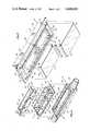
- FIG. 1is an exploded isometric view of a flow-through housing constructed in accordance with the teachings of this invention.
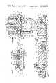
- FIG. 2is a longitudinal sectional view through the flow-through housing.
- FIG. 2ais an enlarged fragmentary sectional view of a portion of FIG. 2 illustrating the tensioning of one of the membranes.
- FIG. 2bis an enlarged sectional view taken generally along line 2b--2b of FIG. 2.
- FIG. 3is an exploded isometric view of the membrane support and the membranes.
- FIG. 1shows an apparatus in the form of a flow through housing assembly 11 which generally comprises a housing section 13, a membrane support 15, membranes 17 and 19 and a sensor support 21.
- the housing section 13, the membrane support 15 and the sensor support 21may each be constructed of a suitable plastic material, such as polycarbonate.
- the housing section 13which may be integrally molded, is hollow and has an inlet 23 and an outlet 25 for coupling the housing assembly 11 into an extracorporeal blood loop.
- the housing 13has an annular, rectangular ledge 27 facing upwardly adjacent its upper end and an annular rectangular flange 29 projecting upwardly from the ledge and surrounding the ledge to define an opening 31 in the upper end of the housing section 13.
- Ramp surfaces 33are provided at the opposite ends of the housing section 13, and longitudinal ledges 35 extend longitudinally from the lower ends of the ramp surfaces 33. Longitudinal grooves 36 (FIG. 2b) are provided in the ledges 35 to catch adhesive used in assembly and keep it out of the blood flow path.
- the membrane support 15which may be integrally molded, has a peripheral flange 37 sized to be received within the flnage 29 and to rest on the ledge 27 of the housing section 13 as shown in FIG. 2.
- the membrane support 15may be adhered to, or otherwise suitably attached to, the housing section 13. When so attached, the housing section 13 and the membrane support 15 provide wall means defining a flow passage 39 which extends longitudinally through the housing from the inlet 23 to the outlet 25. Flow through the flow passage 39 can be in either direction.
- the membrane support 15has a lower wall 41 with recesses in the form of rectangular openings 43 and 45. A web 47 of the wall 41 extends between the openings. The membranes 17 and 19 extend completely across and cover the openings 43 and 45 so that the openings are separated from the passage 39 by the membranes.
- the membrane support 15has an upstanding circumscribing wall 49 which has attachment apertures 51 in its longitudinal portions and orientation slots 53 in its end walls.
- the sensor support 21comprises a peripheral wall 55 extending upwardly from a base 57. Tabs 59 are attached to the opposite ends of the peripheral wall 55.
- the peripheral wall 55has lugs 61 adapted to be received within the apertures 51, respectively, and locator lugs 63 adapted to be received within the slots 53, respectively.
- the lugs 61can be resiliently deflected toward each other to permit the lugs 61 to enter the apertures 51 to securely mount the sensor support 21 on the membrane support 15.
- a removable safety plug(not shown) is mounted on the membrane support 15 in place of the sensor support 21.
- the base 57includes optically transparent dished sections 67 carrying sensors 69, 73, and 75 and a sensor receiver 71 of metal having high thermal conductivity.
- the dished sectionsare separated by a space 81 which is adapted to receive the web 47 as shown in FIG. 2.
- the wall 41supports an annular region of the base 57 of the sensor support 21, and an annular seal 82 (FIGS. 2a and 2b) seals the interface with the membrane support 15.
- the sensors 69, 73, and 75are selected to sense a characteristic of the liquid flowing through the passage 39. Although various different characteristics can be sensed in this embodiment of the invention, the sensor 69 senses the partial pressure of oxygen, the sensor receiver 71 receives a thermistor 86 which senses temperature, the sensor 75 senses the partial pressure of carbon dioxide, and the sensor 73 senses pH. Although sensing can be accomplished in many different ways, in this embodiment, it is accomplished optically using fluorescent techniques as described, for example, in Lubbers et al U.S. Pat. No. 4,003,707 and Heitzmann U.S. Pat. application Ser. No. 425,420 filed on Sept. 28, 1982.
- optical fibers 83are suitably coupled to the sensor support 21 for the purpose of conducting light to and from the respective sensors 69, 73 and 75, and wires 83a are coupled to the thermistor in the sensor receiver 71.
- the optical fibers 83, wires 83a and the thermistorare suitably releasably retained in the sensor support 21 by a molded retainer 84.
- the membranes 17 and 19must be selected so as to pass a component of the liquid, such as blood, which is to be measured.
- the membrane 17is constructed of polytetrafluoroethylene, passes oxygen and serves as a halothane gas and liquid barrier.
- the membrane 19is a microporous membrane that serves as a sterility barrier and passes virtually all blood components of interest, except bacteria. Specifically, aqueous phase materials, including dissolved carbon dioxide and hydrogen ions, are passed. This permits the partial pressure of carbon dioxide and the hydrogen ion concentration to be sensed in accordance with known techniques.
- One suitable material for the membrane 19is a polyvinylidene fluoride which is available from Millipore under the trademark Durapore.
- the membrane support 15has coplanar, annular, rectangular surfaces 85 surrounding the openings 43 and 45, respectively, and a groove 87 of rectangular cross-sectional configuration evenly spaced between the openings 43 and 45.
- Ramp surfaces 89slope upwardly from the opposite ends of the two coplanar surfaces 85.
- the groove 87is spaced from the openings 43 and 45 by flat, coplanar surfaces 91 which form portions of the surfaces 85, respectively.
- Longitudinal grooves or recesses 90extend along the opposite outer longitudinal edges of the surfaces 85 and the ramp surfaces 89, and grooves or recesses 92 extend along three of the inner edges of the surfaces 85, i.e., along all of the such inner edges, except the inner edge adjacent the surface 91.
- the outer edge of the longitudinal portion of each of the grooves 92is coplanar with an inner surface 94 of the housing section 13 (FIG. 2b).
- the membranes 17 and 19are retained on the membrane support 15 by retaining means which includes a retaining bar 93 and adhesive. As shown in FIG. 2a, edge portions of the membrane extend into the groove 87 on the side of the groove adjacent the opening 43.
- the membrane 19is wrapped almost completely around the retaining bar 93 and the membrane 17 extends along two sides of the retaining bar outside of the membrane 19.
- the retaining bar 93has a flat face 95 facing outwardly of the groove, and the membrane 19 extends over the flat face 95 and then into the groove 87 to thereby form a smooth transition between the membranes 17 and 19.
- a region 97 of the end portion of the membrane 19extends beyond the end portion of the membrane 17 within the groove 87 and is adhered to the wall of the groove. This provides a stronger construction and allows the region 97 to be directly adhered to the membrane support 15 even if only one face of the membrane 19 is capable of being adhesively attached.
- the retaining bar 93is sized and configured relative to the groove 87 so that the membranes 17 and 19 are tightly held between the retaining bar and the wall of the groove. This forms a mechanical lock which mechanically locks the end portions of the membranes 17 and 19 to the membrane support 15.
- the retaining bar 93is rectangular, and while this configuration is preferred, it is not essential.
- the vertical dimension of the retaining bar 93 as viewed in FIG. 2ais such as to place the face 95 essentially coplanar with the surfaces 91 so as to maintain the membranes 17 and 19 essentially coplanar and to provide a smooth transition between them.
- Adhesiveis applied between the end portions of the membranes 17 and 19 and between such end portions and the walls of the groove 87 to create both a seal and a bond.
- Peripheral regions of the membranes 17 and 19are adhered to the surfaces of the groove 90, and outer end portions 99 of the membranes are adhered to the ramp surfaces 89.
- the membranes 17 and 19are sized to completely cover their respective openings 43 and 45 and to be essentially coextensive with the surfaces 85, the bottom surface of the grooves 90 and the ramp surfaces 89.
- the longitudinal edge portions of the membranes 17 and 19are clamped between the surfaces 85 of the membrane support 15 and the ledges 35 of the housing section (FIG. 2b).
- the sensor support 21received within, and mounted on, the membrane support 15 as shown in FIG. 2, the sensors 69, 73 and 75, as well as the receiver 71, and the dished sections 67 engage the membranes 17 and 19 along longitudinally extending regions of the membranes and force them downwardly slightly as viewed in FIGS. 2a and 2b to further tension the membranes.
- the desired amount of the downward distension of the membranes 17 and 19depends upon the tendency of the membranes to distend when wet and, in this embodiment, may be, for example, about 0.030 to 0.060 inch.
- This distensionprovides for tight engagement between the sensors and the thermistor receiver 71 and the associated membranes so as to reduce the likelihood of trapping bubbles between the sensors and the thermistor receiver and the membranes, to reduce the time constant of the system, to increase thermal conductivity to the thermistor receiver, and to cause the membrane to lie flat against the sensors and the thermistor receiver.
- the distensiondoes not provide an unacceptable discontinuity for blood flow across the membranes.
- the housing section 13has a longitudinal channel 101 below the distended regions of the membranes to approximately compensate for the projection of the membranes into the flow passage and keep the cross-sectional area of the flow passage 39 approximately constant.
- the distensionis greatly exaggerated in the drawing for clarity. Because the membranes 17 and 19 are tensioned, they will not become loose and allowed to ripple even if they undergo some elongation as a result of becoming wet from the blood in the passage 39. Consequently, the membranes cannot ripple and produce erratic results for that reason.
- the grooves 90provide a space for the adhesive, and the grooves 92 provide a gap which prevents any adhesive that may leak inwardly from adhering the membranes 17 and 19 to the membrane support at that location. Consequently, the tensioning of the membranes 17 and 19 by the sensor support 21 can create an inclined section 103 (FIG. 2b) adjacent each longitudinal membrane edge which prevents the sensor support from shearing the membrane.
- the flow-through housing assembly 11is coupled via the inlet 23 and the outlet 25 into an extracorporeal blood path so that the flow passage 39 forms part of the extracorporeal loop.
- the flow of blood along the membranes 17 and 19is generally parallel to the plane of the membranes.
- the membranes 17 and 19are semi-permeable and pass the blood components identified above and serve as a barrier for the other components of the blood. Consequently, the sensor 69 is exposed to oxygen, and the sensors 73 and 75 are exposed to dissolved carbon dioxide and hydrogen ions.
- Each of these sensorscontains an appropriate indicator which permits the partial pressure of a particular blood gas or the hydrogen ion concentration to be optically determined in accordance with known techniques which form no part of this invention.
Landscapes
- Health & Medical Sciences (AREA)
- Life Sciences & Earth Sciences (AREA)
- Physics & Mathematics (AREA)
- Engineering & Computer Science (AREA)
- Biomedical Technology (AREA)
- General Health & Medical Sciences (AREA)
- Pathology (AREA)
- Biophysics (AREA)
- Chemical & Material Sciences (AREA)
- Molecular Biology (AREA)
- Heart & Thoracic Surgery (AREA)
- Public Health (AREA)
- Immunology (AREA)
- General Physics & Mathematics (AREA)
- Biochemistry (AREA)
- Medical Informatics (AREA)
- Analytical Chemistry (AREA)
- Surgery (AREA)
- Animal Behavior & Ethology (AREA)
- Optics & Photonics (AREA)
- Veterinary Medicine (AREA)
- Hematology (AREA)
- Ecology (AREA)
- Urology & Nephrology (AREA)
- Food Science & Technology (AREA)
- Medicinal Chemistry (AREA)
- Spectroscopy & Molecular Physics (AREA)
- External Artificial Organs (AREA)
Abstract
Description
Claims (18)
Priority Applications (2)
| Application Number | Priority Date | Filing Date | Title |
|---|---|---|---|
| US06/546,493US4640820A (en) | 1983-10-28 | 1983-10-28 | Flow-through housing with blood gas sensors |
| US06/883,094US4786474A (en) | 1983-10-28 | 1986-07-07 | Flow-through housing |
Applications Claiming Priority (1)
| Application Number | Priority Date | Filing Date | Title |
|---|---|---|---|
| US06/546,493US4640820A (en) | 1983-10-28 | 1983-10-28 | Flow-through housing with blood gas sensors |
Related Child Applications (1)
| Application Number | Title | Priority Date | Filing Date |
|---|---|---|---|
| US06/883,094DivisionUS4786474A (en) | 1983-10-28 | 1986-07-07 | Flow-through housing |
Publications (1)
| Publication Number | Publication Date |
|---|---|
| US4640820Atrue US4640820A (en) | 1987-02-03 |
Family
ID=24180682
Family Applications (1)
| Application Number | Title | Priority Date | Filing Date |
|---|---|---|---|
| US06/546,493Expired - LifetimeUS4640820A (en) | 1983-10-28 | 1983-10-28 | Flow-through housing with blood gas sensors |
Country Status (1)
| Country | Link |
|---|---|
| US (1) | US4640820A (en) |
Cited By (52)
| Publication number | Priority date | Publication date | Assignee | Title |
|---|---|---|---|---|
| US4786474A (en)* | 1983-10-28 | 1988-11-22 | Cardiovascular Devices, Inc. | Flow-through housing |
| US4844871A (en)* | 1986-05-13 | 1989-07-04 | Fresenius Ag | Method of determining the partial pressure of gases in blood and an apparatus for performing the method |
| US4928694A (en)* | 1987-01-30 | 1990-05-29 | Minnesota Mining And Manufacturing Company | Intravascular blood parameter measurement system |
| US4934369A (en)* | 1987-01-30 | 1990-06-19 | Minnesota Mining And Manufacturing Company | Intravascular blood parameter measurement system |
| US4951669A (en)* | 1987-01-30 | 1990-08-28 | Minnesota Mining And Manufacturing Company | Blood parameter measurement system |
| US4989606A (en)* | 1987-01-30 | 1991-02-05 | Minnesota Mining And Manufactoring Company | Intravascular blood gas sensing system |
| EP0371953A3 (en)* | 1988-12-01 | 1991-05-15 | AVL Medical Instruments AG | Device for the measurement of the chemical and physical parameters of a fluidic or gaseous medium |
| US5045282A (en)* | 1987-10-16 | 1991-09-03 | Optical Chemical Tech. Ltd. | Optical fiber sensing device for analysis |
| US5048525A (en)* | 1987-01-30 | 1991-09-17 | Minnesota Mining And Manufacturing Company | Blood parameter measurement system with compliant element |
| US5057278A (en)* | 1990-04-26 | 1991-10-15 | Minnesota Mining And Manufacturing Company | Sterile loop calibration system |
| WO1991016416A1 (en)* | 1990-04-26 | 1991-10-31 | Markwell Medical Institute, Inc. | Wearable blood glucose monitor |
| US5081042A (en)* | 1990-03-20 | 1992-01-14 | Minnesota Mining And Manufacturing Company | Ionic component sensor and method for making and using same |
| US5081041A (en)* | 1990-04-03 | 1992-01-14 | Minnesota Mining And Manufacturing Company | Ionic component sensor and method for making and using same |
| US5104623A (en)* | 1990-04-03 | 1992-04-14 | Minnesota Mining And Manufacturing Company | Apparatus and assembly for use in optically sensing a compositional blood parameter |
| USD326718S (en) | 1989-12-26 | 1992-06-02 | Minnesota Mining And Manufacturing Co. | Blood sensor cassette |
| US5171029A (en)* | 1990-04-26 | 1992-12-15 | Minnesota Mining And Manufacturing Company | Seal construction for pump apparatus |
| US5175016A (en)* | 1990-03-20 | 1992-12-29 | Minnesota Mining And Manufacturing Company | Method for making gas sensing element |
| US5278072A (en)* | 1990-04-26 | 1994-01-11 | Minnesota Mining And Manufacturing Company | Calibration system and housing |
| US5289255A (en)* | 1991-03-28 | 1994-02-22 | Minnesota Mining And Manufacturing Co. | Cuvette for use in making a measurement of a blood parameter and assembly utilizing the same |
| US5335658A (en)* | 1992-06-29 | 1994-08-09 | Minnesota Mining And Manufacturing Company | Intravascular blood parameter sensing system |
| US5403746A (en)* | 1993-11-30 | 1995-04-04 | Minnesota Mining And Manufacturing Company | Sensor with improved drift stability |
| US5409666A (en)* | 1991-08-08 | 1995-04-25 | Minnesota Mining And Manufacturing Company | Sensors and methods for sensing |
| US5462052A (en)* | 1987-01-30 | 1995-10-31 | Minnesota Mining And Manufacturing Co. | Apparatus and method for use in measuring a compositional parameter of blood |
| US5494640A (en)* | 1990-04-12 | 1996-02-27 | Hitachi, Ltd. | Device for identifying at least one gaseous component in a gaseous or liquid sample |
| US5508509A (en)* | 1993-11-30 | 1996-04-16 | Minnesota Mining And Manufacturing Company | Sensing elements and methods for uniformly making individual sensing elements |
| US5641458A (en)* | 1995-06-15 | 1997-06-24 | Shockley, Jr.; H. David | Flow through cell assembly |
| US5714122A (en)* | 1995-11-22 | 1998-02-03 | Minnesota Mining And Manufacturing Company | Emulsion for robust sensing |
| US5731218A (en)* | 1993-11-02 | 1998-03-24 | Siemens Aktiengesellschaft | Method for producing a contact hole to a doped region |
| WO1998037801A1 (en) | 1997-02-27 | 1998-09-03 | Minnesota Mining And Manufacturing Company | Cassette for measuring parameters of blood |
| WO1998037800A1 (en)* | 1997-02-27 | 1998-09-03 | Minnesota Mining And Manufacturing Company | Cassette for tonometric calibration |
| US5822137A (en)* | 1997-02-27 | 1998-10-13 | Minnesota Mining & Manufacturing Co. | Assembly for retaining optical components |
| USD408535S (en)* | 1998-02-26 | 1999-04-20 | Minnesota Mining And Manufacturing Company | Sensor cassette for blood gas measurement |
| USD408918S (en) | 1998-02-26 | 1999-04-27 | Minnesota Mining And Manufacturing Company | Calibration cuvette assembly for blood gas measurement |
| USD408917S (en) | 1998-02-26 | 1999-04-27 | Minnesota Mining And Manufacturing Company | Membrane support structure of a flow through cell for blood gas measurement |
| USD409750S (en)* | 1998-02-26 | 1999-05-11 | Minnesota Mining And Manufacturing Company | Flow through cell for blood gas measurement |
| USD410086S (en) | 1998-02-26 | 1999-05-18 | Minnesota Mining And Manufacturing Company | Shunt sensor for blood gas measurement |
| US5958782A (en)* | 1993-10-21 | 1999-09-28 | Minnesota Mining And Manufacturing Company | Cation-sensing composite structure and compounds for use therein |
| US6009339A (en)* | 1997-02-27 | 1999-12-28 | Terumo Cardiovascular Systems Corporation | Blood parameter measurement device |
| US6664111B2 (en)* | 2001-08-22 | 2003-12-16 | 3M Innovative Properties Company | Fluorescence based oxygen sensor systems |
| US6773678B2 (en) | 2000-03-20 | 2004-08-10 | Endress + Hauser Conducta Gesellschaft Fur Mess Und Regeltechnik Mbh + Co. | Mounting system and retractable sensor holder for analytical sensors |
| US20050131305A1 (en)* | 2002-05-17 | 2005-06-16 | Danielson Bo G. | Sensor unit and method for sensing a blood related parameter and system including such a sensor unit |
| US20060052745A1 (en)* | 2004-09-08 | 2006-03-09 | Van Antwerp Nannette M | Blood contacting sensor |
| DE102005018845A1 (en)* | 2005-04-22 | 2006-10-26 | Gansert, Dirk, Dr. | Miniature multifunctional opto sensor control and lock unit for minimal invasive sensor location has measurement chamber and micrometer drive |
| US20070161113A1 (en)* | 2006-01-06 | 2007-07-12 | Ash Stephen R | Ammonia sensor and system for use |
| USD608447S1 (en) | 2005-01-14 | 2010-01-19 | Edwards Lifesciences Corporation | Sensor case |
| US20130171614A1 (en)* | 2010-09-03 | 2013-07-04 | Xvivo Perfusion Ab | Extracorporeal perfusion circuit sensor assembly and methods of isolating sensors thereof in separate dry and wet environments and sterilization of the assembly |
| WO2017050899A1 (en)* | 2015-09-26 | 2017-03-30 | Fresenius Medical Care Deutschland Gmbh | Determination of gases dissolved in blood in the extracorporeal blood flow |
| CN108367111A (en)* | 2015-10-23 | 2018-08-03 | 诺瓦朗公司 | For the intermediary element of medical external fluid line, medical extracorporeal fluid system and the method for measuring gas included in the human or animal body fluid guided in medical extracorporeal fluid system |
| JP2019523682A (en)* | 2016-06-15 | 2019-08-29 | ソリン・グループ・イタリア・ソシエタ・ア・レスポンサビリタ・リミタータSorin Group Italia S.r.l. | Method and device for monitoring blood |
| JP2020165988A (en)* | 2020-06-24 | 2020-10-08 | ソリン・グループ・イタリア・ソシエタ・ア・レスポンサビリタ・リミタータSorin Group Italia S.r.l. | Methods and devices for monitoring blood |
| JP2022078022A (en)* | 2020-06-24 | 2022-05-24 | ソリン・グループ・イタリア・ソシエタ・ア・レスポンサビリタ・リミタータ | Method and device for monitoring blood |
| US11357899B2 (en) | 2014-05-15 | 2022-06-14 | Novalung Gmbh | Measuring device and method for measuring a property of a fluid in a line |
Citations (8)
| Publication number | Priority date | Publication date | Assignee | Title |
|---|---|---|---|---|
| US3907687A (en)* | 1968-12-07 | 1975-09-23 | Baxter Laboratories Inc | Plate dialyzer |
| US3977976A (en)* | 1973-08-05 | 1976-08-31 | Spaan Josef A E | Apparatus for exchange of substances between two media on opposite sides of a membrane |
| US3980564A (en)* | 1973-05-29 | 1976-09-14 | Rhone-Poulenc S.A. | Membrane support-plates for fluid separating apparatus and apparatus using such support-plates |
| US4003707A (en)* | 1975-02-28 | 1977-01-18 | Max-Planck-Gesellschaft Zur Forderung Der Wissenschaften E.V. | Method and arrangement for measuring the concentration of gases |
| US4038191A (en)* | 1975-10-14 | 1977-07-26 | Davis Harold R | Manifold for ultra filtration machine |
| US4184962A (en)* | 1977-10-14 | 1980-01-22 | Extracorporeal Medical Specialties, Inc. | Totally wrapped coil permeation device and artificial kidney |
| US4404100A (en)* | 1980-05-13 | 1983-09-13 | Medical Incorporated | Hemodialyzer with pleated membrane |
| US4415447A (en)* | 1978-12-21 | 1983-11-15 | Rhone-Poulenc Industries | Separatory apparatus comprising means for anchoring a semi-permeable membrane to a support member |
- 1983
- 1983-10-28USUS06/546,493patent/US4640820A/ennot_activeExpired - Lifetime
Patent Citations (8)
| Publication number | Priority date | Publication date | Assignee | Title |
|---|---|---|---|---|
| US3907687A (en)* | 1968-12-07 | 1975-09-23 | Baxter Laboratories Inc | Plate dialyzer |
| US3980564A (en)* | 1973-05-29 | 1976-09-14 | Rhone-Poulenc S.A. | Membrane support-plates for fluid separating apparatus and apparatus using such support-plates |
| US3977976A (en)* | 1973-08-05 | 1976-08-31 | Spaan Josef A E | Apparatus for exchange of substances between two media on opposite sides of a membrane |
| US4003707A (en)* | 1975-02-28 | 1977-01-18 | Max-Planck-Gesellschaft Zur Forderung Der Wissenschaften E.V. | Method and arrangement for measuring the concentration of gases |
| US4038191A (en)* | 1975-10-14 | 1977-07-26 | Davis Harold R | Manifold for ultra filtration machine |
| US4184962A (en)* | 1977-10-14 | 1980-01-22 | Extracorporeal Medical Specialties, Inc. | Totally wrapped coil permeation device and artificial kidney |
| US4415447A (en)* | 1978-12-21 | 1983-11-15 | Rhone-Poulenc Industries | Separatory apparatus comprising means for anchoring a semi-permeable membrane to a support member |
| US4404100A (en)* | 1980-05-13 | 1983-09-13 | Medical Incorporated | Hemodialyzer with pleated membrane |
Non-Patent Citations (2)
| Title |
|---|
| Siggaard Andersen; The Acid Base Status of the Blood, The Williams & Williams Co. 1974, p. 178.* |
| Siggaard-Andersen; The Acid-Base Status of the Blood, The Williams & Williams Co. 1974, p. 178. |
Cited By (83)
| Publication number | Priority date | Publication date | Assignee | Title |
|---|---|---|---|---|
| US4786474A (en)* | 1983-10-28 | 1988-11-22 | Cardiovascular Devices, Inc. | Flow-through housing |
| US4844871A (en)* | 1986-05-13 | 1989-07-04 | Fresenius Ag | Method of determining the partial pressure of gases in blood and an apparatus for performing the method |
| US4989606A (en)* | 1987-01-30 | 1991-02-05 | Minnesota Mining And Manufactoring Company | Intravascular blood gas sensing system |
| US5462052A (en)* | 1987-01-30 | 1995-10-31 | Minnesota Mining And Manufacturing Co. | Apparatus and method for use in measuring a compositional parameter of blood |
| US4951669A (en)* | 1987-01-30 | 1990-08-28 | Minnesota Mining And Manufacturing Company | Blood parameter measurement system |
| US4934369A (en)* | 1987-01-30 | 1990-06-19 | Minnesota Mining And Manufacturing Company | Intravascular blood parameter measurement system |
| US5048525A (en)* | 1987-01-30 | 1991-09-17 | Minnesota Mining And Manufacturing Company | Blood parameter measurement system with compliant element |
| US4928694A (en)* | 1987-01-30 | 1990-05-29 | Minnesota Mining And Manufacturing Company | Intravascular blood parameter measurement system |
| US5045282A (en)* | 1987-10-16 | 1991-09-03 | Optical Chemical Tech. Ltd. | Optical fiber sensing device for analysis |
| AU620116B2 (en)* | 1988-08-08 | 1992-02-13 | Minnesota Mining And Manufacturing Company | Intravascular blood gas sensing system |
| EP0613651A3 (en)* | 1988-08-08 | 1994-10-12 | Minnesota Mining & Mfg | Intravascular blood gas sensing system. |
| EP0371953A3 (en)* | 1988-12-01 | 1991-05-15 | AVL Medical Instruments AG | Device for the measurement of the chemical and physical parameters of a fluidic or gaseous medium |
| USD326718S (en) | 1989-12-26 | 1992-06-02 | Minnesota Mining And Manufacturing Co. | Blood sensor cassette |
| US5081042A (en)* | 1990-03-20 | 1992-01-14 | Minnesota Mining And Manufacturing Company | Ionic component sensor and method for making and using same |
| US5175016A (en)* | 1990-03-20 | 1992-12-29 | Minnesota Mining And Manufacturing Company | Method for making gas sensing element |
| US5284775A (en)* | 1990-03-20 | 1994-02-08 | Minnesota Mining And Manufacturing Company | Gas sensing element and method for making same |
| US5104623A (en)* | 1990-04-03 | 1992-04-14 | Minnesota Mining And Manufacturing Company | Apparatus and assembly for use in optically sensing a compositional blood parameter |
| JPH0488909U (en)* | 1990-04-03 | 1992-08-03 | ||
| US5081041A (en)* | 1990-04-03 | 1992-01-14 | Minnesota Mining And Manufacturing Company | Ionic component sensor and method for making and using same |
| JP2590382Y2 (en) | 1990-04-03 | 1999-02-10 | ミネソタ マイニング アンド マニュファクチャリング カンパニー | Assembly for optical detection of blood parameters |
| US5494640A (en)* | 1990-04-12 | 1996-02-27 | Hitachi, Ltd. | Device for identifying at least one gaseous component in a gaseous or liquid sample |
| EP0454033A1 (en)* | 1990-04-26 | 1991-10-30 | Minnesota Mining And Manufacturing Company | Sterile loop calibration system |
| US5171029A (en)* | 1990-04-26 | 1992-12-15 | Minnesota Mining And Manufacturing Company | Seal construction for pump apparatus |
| US5057278A (en)* | 1990-04-26 | 1991-10-15 | Minnesota Mining And Manufacturing Company | Sterile loop calibration system |
| US5348706A (en)* | 1990-04-26 | 1994-09-20 | Minnesota Mining And Manufacturing Company | Calibration system and method for making |
| US5278072A (en)* | 1990-04-26 | 1994-01-11 | Minnesota Mining And Manufacturing Company | Calibration system and housing |
| WO1991016416A1 (en)* | 1990-04-26 | 1991-10-31 | Markwell Medical Institute, Inc. | Wearable blood glucose monitor |
| US5420038A (en)* | 1990-04-26 | 1995-05-30 | Minnesota Mining And Manufacturing Company | Calibration system and housing |
| US5289255A (en)* | 1991-03-28 | 1994-02-22 | Minnesota Mining And Manufacturing Co. | Cuvette for use in making a measurement of a blood parameter and assembly utilizing the same |
| US5498549A (en)* | 1991-08-08 | 1996-03-12 | Minnesota Mining And Manufacturing Company | Sensors and methods for sensing |
| US5409666A (en)* | 1991-08-08 | 1995-04-25 | Minnesota Mining And Manufacturing Company | Sensors and methods for sensing |
| US5421328A (en)* | 1992-06-29 | 1995-06-06 | Minnesota Mining And Manufacturing Company | Intravascular blood parameter sensing system |
| US5335658A (en)* | 1992-06-29 | 1994-08-09 | Minnesota Mining And Manufacturing Company | Intravascular blood parameter sensing system |
| US5958782A (en)* | 1993-10-21 | 1999-09-28 | Minnesota Mining And Manufacturing Company | Cation-sensing composite structure and compounds for use therein |
| US5731218A (en)* | 1993-11-02 | 1998-03-24 | Siemens Aktiengesellschaft | Method for producing a contact hole to a doped region |
| US5403746A (en)* | 1993-11-30 | 1995-04-04 | Minnesota Mining And Manufacturing Company | Sensor with improved drift stability |
| US5508509A (en)* | 1993-11-30 | 1996-04-16 | Minnesota Mining And Manufacturing Company | Sensing elements and methods for uniformly making individual sensing elements |
| US5607645A (en)* | 1993-11-30 | 1997-03-04 | Minnesota Mining And Manufacturing Company | Sensor with improved drift stability |
| US5882936A (en)* | 1993-11-30 | 1999-03-16 | Minnesota Mining And Manufacturing Company | Method of making a sensor with improved drift stability |
| US5641458A (en)* | 1995-06-15 | 1997-06-24 | Shockley, Jr.; H. David | Flow through cell assembly |
| US5714122A (en)* | 1995-11-22 | 1998-02-03 | Minnesota Mining And Manufacturing Company | Emulsion for robust sensing |
| US6217828B1 (en) | 1995-11-22 | 2001-04-17 | Terumo Cardiovascular Systems Corporation | Emulsion for robust sensing |
| WO1998037800A1 (en)* | 1997-02-27 | 1998-09-03 | Minnesota Mining And Manufacturing Company | Cassette for tonometric calibration |
| US6208880B1 (en) | 1997-02-27 | 2001-03-27 | Terumo Cardiovascular Systems Corporation | Blood parameter measurement device |
| WO1998037801A1 (en) | 1997-02-27 | 1998-09-03 | Minnesota Mining And Manufacturing Company | Cassette for measuring parameters of blood |
| US6101406A (en)* | 1997-02-27 | 2000-08-08 | Terumo Cardiovascular Systems Corporation | Cassette for measuring parameters of blood |
| US6009339A (en)* | 1997-02-27 | 1999-12-28 | Terumo Cardiovascular Systems Corporation | Blood parameter measurement device |
| US5997818A (en)* | 1997-02-27 | 1999-12-07 | Minnesota Mining And Manufacturing Company | Cassette for tonometric calibration |
| US5822137A (en)* | 1997-02-27 | 1998-10-13 | Minnesota Mining & Manufacturing Co. | Assembly for retaining optical components |
| USD410086S (en) | 1998-02-26 | 1999-05-18 | Minnesota Mining And Manufacturing Company | Shunt sensor for blood gas measurement |
| USD409750S (en)* | 1998-02-26 | 1999-05-11 | Minnesota Mining And Manufacturing Company | Flow through cell for blood gas measurement |
| USD408917S (en) | 1998-02-26 | 1999-04-27 | Minnesota Mining And Manufacturing Company | Membrane support structure of a flow through cell for blood gas measurement |
| USD408535S (en)* | 1998-02-26 | 1999-04-20 | Minnesota Mining And Manufacturing Company | Sensor cassette for blood gas measurement |
| USD408918S (en) | 1998-02-26 | 1999-04-27 | Minnesota Mining And Manufacturing Company | Calibration cuvette assembly for blood gas measurement |
| US6773678B2 (en) | 2000-03-20 | 2004-08-10 | Endress + Hauser Conducta Gesellschaft Fur Mess Und Regeltechnik Mbh + Co. | Mounting system and retractable sensor holder for analytical sensors |
| US6664111B2 (en)* | 2001-08-22 | 2003-12-16 | 3M Innovative Properties Company | Fluorescence based oxygen sensor systems |
| US20050131305A1 (en)* | 2002-05-17 | 2005-06-16 | Danielson Bo G. | Sensor unit and method for sensing a blood related parameter and system including such a sensor unit |
| US20090149728A1 (en)* | 2004-09-08 | 2009-06-11 | Medtronic Minimed, Inc. | Blood contacting sensor |
| US8352011B2 (en) | 2004-09-08 | 2013-01-08 | Medtronic Minimed, Inc. | Blood contacting sensor |
| US7468033B2 (en)* | 2004-09-08 | 2008-12-23 | Medtronic Minimed, Inc. | Blood contacting sensor |
| US20060052745A1 (en)* | 2004-09-08 | 2006-03-09 | Van Antwerp Nannette M | Blood contacting sensor |
| USD608447S1 (en) | 2005-01-14 | 2010-01-19 | Edwards Lifesciences Corporation | Sensor case |
| DE102005018845B4 (en)* | 2005-04-22 | 2007-05-16 | Dirk Gansert | Miniaturized and multifunctional optosensory measuring and control sluice |
| DE102005018845A1 (en)* | 2005-04-22 | 2006-10-26 | Gansert, Dirk, Dr. | Miniature multifunctional opto sensor control and lock unit for minimal invasive sensor location has measurement chamber and micrometer drive |
| WO2007081565A3 (en)* | 2006-01-06 | 2007-11-29 | Renal Solutions Inc | Ammonia sensor and system for use |
| AU2006335104B2 (en)* | 2006-01-06 | 2012-04-12 | Renal Solutions, Inc. | Ammonia sensor and system for use |
| US8409864B2 (en) | 2006-01-06 | 2013-04-02 | Renal Solutions, Inc. | Ammonia sensor and system for use |
| CN101400997B (en)* | 2006-01-06 | 2013-04-24 | 雷纳尔解决方法公司 | Ammonia sensor and system using ammonia sensor |
| US20070161113A1 (en)* | 2006-01-06 | 2007-07-12 | Ash Stephen R | Ammonia sensor and system for use |
| US20130171614A1 (en)* | 2010-09-03 | 2013-07-04 | Xvivo Perfusion Ab | Extracorporeal perfusion circuit sensor assembly and methods of isolating sensors thereof in separate dry and wet environments and sterilization of the assembly |
| US11357899B2 (en) | 2014-05-15 | 2022-06-14 | Novalung Gmbh | Measuring device and method for measuring a property of a fluid in a line |
| WO2017050899A1 (en)* | 2015-09-26 | 2017-03-30 | Fresenius Medical Care Deutschland Gmbh | Determination of gases dissolved in blood in the extracorporeal blood flow |
| CN108136099B (en)* | 2015-09-26 | 2021-07-27 | 费森尤斯医疗保健德国有限公司 | Blood processing equipment and corresponding method |
| CN108136099A (en)* | 2015-09-26 | 2018-06-08 | 费森尤斯医疗保健德国有限公司 | The gas of dissolving in blood is determined in recycling in vitro |
| CN108367111A (en)* | 2015-10-23 | 2018-08-03 | 诺瓦朗公司 | For the intermediary element of medical external fluid line, medical extracorporeal fluid system and the method for measuring gas included in the human or animal body fluid guided in medical extracorporeal fluid system |
| JP2018531109A (en)* | 2015-10-23 | 2018-10-25 | ノヴァラング ゲゼルシャフト ミット ベシュレンクテル ハフツング | Intermediate elements for medical extracorporeal fluid lines, medical extracorporeal fluid systems, and methods for measuring gases contained in human or animal body fluids introduced in medical extracorporeal fluid systems |
| US20180303994A1 (en)* | 2015-10-23 | 2018-10-25 | Novalung Gmbh | Intermediate element for a medical extracorporeal fluid line, and system and method associated therewith |
| US10814054B2 (en)* | 2015-10-23 | 2020-10-27 | Novalung Gmbh | Intermediate element for a medical extracorporeal fluid line, and system and method associated therewith |
| JP2019523682A (en)* | 2016-06-15 | 2019-08-29 | ソリン・グループ・イタリア・ソシエタ・ア・レスポンサビリタ・リミタータSorin Group Italia S.r.l. | Method and device for monitoring blood |
| US11226282B2 (en)* | 2016-06-15 | 2022-01-18 | Sorin Group Italia S.R.L. | Methods and devices for monitoring blood |
| US11994460B2 (en) | 2016-06-15 | 2024-05-28 | Sorin Group Italia S.R.L. | Methods and devices for monitoring blood |
| JP2020165988A (en)* | 2020-06-24 | 2020-10-08 | ソリン・グループ・イタリア・ソシエタ・ア・レスポンサビリタ・リミタータSorin Group Italia S.r.l. | Methods and devices for monitoring blood |
| JP2022078022A (en)* | 2020-06-24 | 2022-05-24 | ソリン・グループ・イタリア・ソシエタ・ア・レスポンサビリタ・リミタータ | Method and device for monitoring blood |
Similar Documents
| Publication | Publication Date | Title |
|---|---|---|
| US4640820A (en) | Flow-through housing with blood gas sensors | |
| US4786474A (en) | Flow-through housing | |
| US5104623A (en) | Apparatus and assembly for use in optically sensing a compositional blood parameter | |
| US4238207A (en) | Method of mounting a filter membrane | |
| US4298358A (en) | Gas separating and venting filter | |
| US6542761B1 (en) | Multifunction sensor | |
| US4190426A (en) | Gas separating and venting filter | |
| EP1122114A2 (en) | Weldable mount for fuel systems component | |
| EP0153928A1 (en) | IN-LINE FILTER. | |
| KR20110102423A (en) | Fluid filter assembly including seal | |
| US5641458A (en) | Flow through cell assembly | |
| JPH03502733A (en) | Calibration device for sensor calibration | |
| SE8106647L (en) | GAS PARTIAL PRESSURE MONITORING DEVICE | |
| US5100549A (en) | Tubular membrane module | |
| ATE175587T1 (en) | SPIRALLY WOUND FILTRATION MODULE WITH A FLANGE TO PREVENT BYPASS FLOW | |
| ES2141739T3 (en) | UNIFORMLY DISTRIBUTED ENRICHMENT OF A SUBSTANCE PRESENT IN SOLUTION OVER THE FINE PORE FACE OF AN ASYMMETRIC POROUS MEMBRANE. | |
| HU220361B (en) | Process for manufacturing a venting cap and the venting cap | |
| JPH048363Y2 (en) | ||
| JPH029876Y2 (en) | ||
| JPH09290140A (en) | Membrane module | |
| KR900006015A (en) | Thin film separator | |
| JP6610061B2 (en) | Hollow fiber membrane module | |
| JPH0118178Y2 (en) | ||
| Casey | A New Method for Detecting Anisotropy with Regard to Oxygen Diffusion in Biological Liquids | |
| JPH0346823Y2 (en) |
Legal Events
| Date | Code | Title | Description |
|---|---|---|---|
| AS | Assignment | Owner name:CARDIOVASCULAR DEVICES, INC. 2801 BARRANCA ROAD, I Free format text:ASSIGNMENT OF ASSIGNORS INTEREST.;ASSIGNOR:COOPER, ROBERT P.;REEL/FRAME:004191/0086 Effective date:19831107 | |
| STCF | Information on status: patent grant | Free format text:PATENTED CASE | |
| FEPP | Fee payment procedure | Free format text:PAYOR NUMBER ASSIGNED (ORIGINAL EVENT CODE: ASPN); ENTITY STATUS OF PATENT OWNER: LARGE ENTITY | |
| AS | Assignment | Owner name:MINNESOTA MINING AND MANUFACTURING COMPANY, MINNES Free format text:ASSIGNMENT OF ASSIGNORS INTEREST.;ASSIGNOR:CARDIOVASCULAR DEVICES, INC., A CORP. OF CA;REEL/FRAME:005230/0083 Effective date:19890119 | |
| FPAY | Fee payment | Year of fee payment:4 | |
| FPAY | Fee payment | Year of fee payment:8 | |
| FPAY | Fee payment | Year of fee payment:12 | |
| AS | Assignment | Owner name:TERUMO CARDIOVASCULAR SYSTEMS CORPORATION, NEW JER Free format text:ASSIGNMENT OF ASSIGNORS INTEREST;ASSIGNOR:MINNESOTA MINING & MANUFACTURING COMPANY;REEL/FRAME:010043/0831 Effective date:19990630 | |
| AS | Assignment | Owner name:TERUMO CARDIOVASCULAR SYSTEMS CORPORATION, NEW JER Free format text:ASSIGNMENT OF ASSIGNORS INTEREST;ASSIGNOR:MINNESOTA MINING AND MANUFACTURING COMPANY;REEL/FRAME:010609/0395 Effective date:19991123 |