US4640479A - Strain relief grommet - Google Patents
Strain relief grommetDownload PDFInfo
- Publication number
- US4640479A US4640479AUS06/723,007US72300785AUS4640479AUS 4640479 AUS4640479 AUS 4640479AUS 72300785 AUS72300785 AUS 72300785AUS 4640479 AUS4640479 AUS 4640479A
- Authority
- US
- United States
- Prior art keywords
- cord
- cylinder
- cable tie
- grommet
- split
- Prior art date
- Legal status (The legal status is an assumption and is not a legal conclusion. Google has not performed a legal analysis and makes no representation as to the accuracy of the status listed.)
- Expired - Fee Related
Links
- 238000000034methodMethods0.000claimsdescription4
- 238000005299abrasionMethods0.000claims3
- 239000002184metalSubstances0.000description3
- 238000003780insertionMethods0.000description1
- 230000037431insertionEffects0.000description1
- 238000009413insulationMethods0.000description1
- 210000002105tongueAnatomy0.000description1
Images

Classifications
- H—ELECTRICITY
- H02—GENERATION; CONVERSION OR DISTRIBUTION OF ELECTRIC POWER
- H02G—INSTALLATION OF ELECTRIC CABLES OR LINES, OR OF COMBINED OPTICAL AND ELECTRIC CABLES OR LINES
- H02G3/00—Installations of electric cables or lines or protective tubing therefor in or on buildings, equivalent structures or vehicles
- H02G3/02—Details
- H02G3/06—Joints for connecting lengths of protective tubing or channels, to each other or to casings, e.g. to distribution boxes; Ensuring electrical continuity in the joint
- H02G3/0616—Joints for connecting tubing to casing
- H02G3/0625—Joints for connecting tubing to casing with means for preventing disengagement of conductors
- H02G3/0641—Joints for connecting tubing to casing with means for preventing disengagement of conductors with means distorted around the conductors
Definitions
- This inventionrelates to strain relief grommets, and more particularly, to grommets which may apply a controlled amount of compressive forces upon a cord, wire, or line, and especially, upon a power line used in electrical equipment.
- a widely used strain reliefhas two hard plastic piece parts which nest together and form a twisting path for the cord to pass through. This twisting path applies a mechanical stress to the cord; however, the two parts must be squeezed together very tightly in order to pass through a hole in a chassis. This uncontrolled and uncontrollable squeezing adds further stress to the wire. Therefore, there is sometimes a tendency for the wire to become damaged.
- an object of the inventionis to provide new and improved means for and methods of supplying strain relief whereby any stress placed upon the cord is closely controllable.
- Another object of the inventionis to provide a strain relief system which uses existing tools to supply a controlled stress.
- a strain relief devicein the form of a split cylindrical grommet having a section through which a cord passes and about which a cable tie may be wrapped.
- a conventional cable tie gunmay be set to pull the cable tie with a predetermined tension in order to pull the split grommet together with precisely that tension.
- any wire in the cord passing through the grommetreceives no more than a maximum stress which is set by that tension in the cable tie.
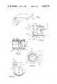
- FIG. 1is a perspective view of an electrical chassis with the inventive strain relief grommet in place;
- FIG. 2is a side elevation of the inventive strain relief grommet in its relaxed state before it is either tensioned or inserted into the chassis;
- FIG. 3is a cross section (taken along line 3--3, FIG. 2) of the inventive grommet taken in the plane of a cord passing through it;
- FIG. 4is a cross section of the grommet (taken along line 4--4, FIG. 2) in a plane which is perpendicular to the section plane of FIG. 3;
- FIG. 5is a perspective view of a part of a cable tie which is used to secure and apply a predetermined stress to the grommet;
- FIG. 6is a side elevation which shows an inventive grommet in a chassis mounting hole with the cable tie securing a captured two wire cord in place;
- FIG. 7is a side elevation which shows the inventive grommet, strain relief device of FIGS. 1-6 mounted on a push type of mounting base;
- FIG. 8is a cross section taken along line 8--8 of FIG. 7;
- FIG. 9shows a side elevation of an embodiment having a screw mount base.
- FIG. 1shows a chassis 20 which may represent any suitable device that requires strain relief.
- the chassis 20may be a sheet metal device which supports parts of a radio receiver powered via a conventional power cord or line 22.
- the power cord 22is mechanically tied to the chassis 20 by the inventive strain relief grommet 24. Therefore, if the cord 22 is pulled, the sheet metal of chassis 20 receives the force and no stress is placed upon any components which are mounted on the chassis or connected to cord 22.
- FIGS. 2-4The structure of the grommet is best seen in FIGS. 2-4.
- An end of split cylinder 24may be pushed through a hole in chassis 20 where a pair of spaced parallel annular retaining rings 28, 30 receive and embrace the chassis metal.
- a third annular ring 32is spaced away from the central annular ring 30 by a distance 34 which corresponds to the width of a preferred cable tie. Therefore, a cable tie (FIG. 5) may be wrapped around area 34 after which it may be drawn tightly around the cylinder.
- An axial bore identified by dot-dashed line 35receives a cord, wire, line, cable, rope, or other device which is to be given strain relief.
- a pair of tongues 36, 40 and grooves 38, 42cooperate to align the two sides of the split cylinder, when the cable tie is drawn tightly.
- the split cylinder 24has a plurality of internal annular ridges 44 which tend to be squeezed into the jacket 46 (FIG. 6) of a power line cord 22 and to hold it tightly.
- the open sector space between the edges of the split cylinderforms an angle "a" (FIG. 4) which may be in the order of about 30°.
- the cord 22is threaded through the central opening 48 in the area of the space represented by angle "a".
- the cylinderIn the area 34 where the cable tie is wrapped around the grommet, the cylinder has a 90° open sector "b". This sector provides ample room for easy insertion of the electric cord or line 22 into the bore of the grommet. Also, the sector "b" provides a substantial area for perimeter reduction so that the grommet may be reduced in diameter to squeeze the ridges 44 into the jacket of cord 22.
- the cord 22is placed in bore 35 of grommet 24, which is then pushed through a mounting hole 50 (FIG. 6) in chassis 20.
- the chassisis captured between annular rings 28, 30.
- a cable tie 52is placed around the space 34 and drawn tightly, to squeeze the cord 22 between the ridges 44 (FIGS. 2, 3).
- a suitable cable tieis described in U.S. Pat. No. 3,605,199, and shown in FIG. 5.
- a cable tieis an integral plastic piece part comprising a head 54 and a strap 56, which are somewhat similar to a belt with a buckle.
- the straphas a rack of transverse teeth 58 formed thereon.
- An end 60 of the strapis brought into alignment with and then pushed through an eye 62 in the head.
- a cable tie gunAs the strap end 60 emerges from the eye 62, it may be seized by a cable tie gun and pulled tightly into a locked position where a pawl 64 (FIG. 6) in eye 62 locks against a tooth in the rack of teeth 58. Then, the strap end is cut off close to the head 54.
- Cable tie gunsare quite well known devices which are the subject matter of International Class B21F 9/02; U.S. Class 140/123.6).
- a conventional cable tie gunhas an adjustable mechanism which may be set to exert a predetermined pull upon the strap 56, before the strap end is cut off.
- the cable tie 52may pull the section "b" (FIG. 4) toward a closed position with, say, a 30-pound pull. Therefore, no more than the amount of stress which is caused by a 30-pound pull may be placed on the wires as the internal ridges 44 are squeezed against the outer insulation of cord 22.
- FIGS. 7 and 8show a grommet 24 having a push mount 70 which may be pushed through a hole in a chassis in order to attach the grommet thereto.
- FIG. 9shows an embodiment wherein the grommet is attached to the chassis 20 by means of a screw 74 and nut 76. Therefore, the term "mounting means" is to be construed broadly enough to cover all of these and equivalent devices.
Landscapes
- Engineering & Computer Science (AREA)
- Architecture (AREA)
- Civil Engineering (AREA)
- Structural Engineering (AREA)
- Installation Of Indoor Wiring (AREA)
- Insulating Bodies (AREA)
Abstract
Description
This is a continuation of U.S. patent application, Ser. No. 06/462,312, filed Jan. 31, 1983 abandoned 5.23.85.
This invention relates to strain relief grommets, and more particularly, to grommets which may apply a controlled amount of compressive forces upon a cord, wire, or line, and especially, upon a power line used in electrical equipment.
Conventionally, electrical equipment has a power cord or line which extends from a chassis to a wall outlet. If the cord is not mechanically secured (called "strain relief") to the chassis, any forces pulling upon the line are transferred directly to the electrical components connected thereto. These forces would soon break the component or the connection thereto and make the circuit inoperative. Therefore, it is conventional to provide strain relief by mechanically tying the power cord or line to the chassis to transfer any mechanical pull upon the cord directly to the chassis.
The foregoing paragraph speaks of strain relief for electrical cords. Actually, there are many other cords that may utilize strain relief. For example, a clothes line may be attached to a bracket on a pole. Therefore, this disclosure is to be construed broadly enough to cover any and all strain relief on any comparable cords.
A widely used strain relief has two hard plastic piece parts which nest together and form a twisting path for the cord to pass through. This twisting path applies a mechanical stress to the cord; however, the two parts must be squeezed together very tightly in order to pass through a hole in a chassis. This uncontrolled and uncontrollable squeezing adds further stress to the wire. Therefore, there is sometimes a tendency for the wire to become damaged.
Accordingly, an object of the invention is to provide new and improved means for and methods of supplying strain relief whereby any stress placed upon the cord is closely controllable.
Another object of the invention is to provide a strain relief system which uses existing tools to supply a controlled stress.
In keeping with an aspect of the invention, these and other objects are provided by a strain relief device in the form of a split cylindrical grommet having a section through which a cord passes and about which a cable tie may be wrapped. A conventional cable tie gun may be set to pull the cable tie with a predetermined tension in order to pull the split grommet together with precisely that tension. Thus, any wire in the cord passing through the grommet receives no more than a maximum stress which is set by that tension in the cable tie.
A preferred embodiment of the invention is seen in the attached drawing, wherein:
FIG. 1 is a perspective view of an electrical chassis with the inventive strain relief grommet in place;
FIG. 2 is a side elevation of the inventive strain relief grommet in its relaxed state before it is either tensioned or inserted into the chassis;
FIG. 3 is a cross section (taken alongline 3--3, FIG. 2) of the inventive grommet taken in the plane of a cord passing through it;
FIG. 4 is a cross section of the grommet (taken alongline 4--4, FIG. 2) in a plane which is perpendicular to the section plane of FIG. 3;
FIG. 5 is a perspective view of a part of a cable tie which is used to secure and apply a predetermined stress to the grommet;
FIG. 6 is a side elevation which shows an inventive grommet in a chassis mounting hole with the cable tie securing a captured two wire cord in place;
FIG. 7 is a side elevation which shows the inventive grommet, strain relief device of FIGS. 1-6 mounted on a push type of mounting base;
FIG. 8 is a cross section taken alongline 8--8 of FIG. 7; and
FIG. 9 shows a side elevation of an embodiment having a screw mount base.
FIG. 1 shows achassis 20 which may represent any suitable device that requires strain relief. For example, thechassis 20 may be a sheet metal device which supports parts of a radio receiver powered via a conventional power cord orline 22. Thepower cord 22 is mechanically tied to thechassis 20 by the inventivestrain relief grommet 24. Therefore, if thecord 22 is pulled, the sheet metal ofchassis 20 receives the force and no stress is placed upon any components which are mounted on the chassis or connected tocord 22.
The structure of the grommet is best seen in FIGS. 2-4. An end of splitcylinder 24 may be pushed through a hole inchassis 20 where a pair of spaced parallelannular retaining rings annular ring 32 is spaced away from the centralannular ring 30 by adistance 34 which corresponds to the width of a preferred cable tie. Therefore, a cable tie (FIG. 5) may be wrapped aroundarea 34 after which it may be drawn tightly around the cylinder.
An axial bore identified by dot-dashed line 35 (FIGS. 2, 3) receives a cord, wire, line, cable, rope, or other device which is to be given strain relief. A pair oftongues grooves
Inside thebore 35, the splitcylinder 24 has a plurality of internalannular ridges 44 which tend to be squeezed into the jacket 46 (FIG. 6) of apower line cord 22 and to hold it tightly. In the region of the chassis holdingannular rings cord 22 is threaded through thecentral opening 48 in the area of the space represented by angle "a".
In thearea 34 where the cable tie is wrapped around the grommet, the cylinder has a 90° open sector "b". This sector provides ample room for easy insertion of the electric cord orline 22 into the bore of the grommet. Also, the sector "b" provides a substantial area for perimeter reduction so that the grommet may be reduced in diameter to squeeze theridges 44 into the jacket ofcord 22.
In operation, thecord 22 is placed inbore 35 ofgrommet 24, which is then pushed through a mounting hole 50 (FIG. 6) inchassis 20. The chassis is captured betweenannular rings cable tie 52 is placed around thespace 34 and drawn tightly, to squeeze thecord 22 between the ridges 44 (FIGS. 2, 3).
A suitable cable tie is described in U.S. Pat. No. 3,605,199, and shown in FIG. 5. In general, a cable tie is an integral plastic piece part comprising ahead 54 and astrap 56, which are somewhat similar to a belt with a buckle. The strap has a rack oftransverse teeth 58 formed thereon. Anend 60 of the strap is brought into alignment with and then pushed through aneye 62 in the head. As thestrap end 60 emerges from theeye 62, it may be seized by a cable tie gun and pulled tightly into a locked position where a pawl 64 (FIG. 6) ineye 62 locks against a tooth in the rack ofteeth 58. Then, the strap end is cut off close to thehead 54. (Cable tie guns are quite well known devices which are the subject matter of International Class B21F 9/02; U.S. Class 140/123.6).
A conventional cable tie gun has an adjustable mechanism which may be set to exert a predetermined pull upon thestrap 56, before the strap end is cut off. Thus, for example, thecable tie 52 may pull the section "b" (FIG. 4) toward a closed position with, say, a 30-pound pull. Therefore, no more than the amount of stress which is caused by a 30-pound pull may be placed on the wires as theinternal ridges 44 are squeezed against the outer insulation ofcord 22.
The spaced parallelannular rings rings grommet 24 having apush mount 70 which may be pushed through a hole in a chassis in order to attach the grommet thereto. FIG. 9 shows an embodiment wherein the grommet is attached to thechassis 20 by means of ascrew 74 andnut 76. Therefore, the term "mounting means" is to be construed broadly enough to cover all of these and equivalent devices.
Those who are skilled in the art will readily perceive how to modify the invention. Therefore, the appended claims are to be construed to cover all equivalent structures which fall within the true scope and spirit of the invention.
Claims (10)
1. A plastic strain relief eyelet device for protecting, insulating, and holding a cord passing through a perforation in a chassis against abrasion and axial forces exerted by pulling upon said cord; said strain relief device comprising a cylindrical ring with a C-shaped cross section having a single longitudinal open split sector along one side and having a substantially uniform internal diameter throughout forming a grommet, a spaced parallel pair of annular shoulder means formed on an outside surface of said C-shaped cylindrical ring for securely mounting said grommet in a perforation on a chassis by being pushed therethrough, one of said shoulder means being at a first end of said grommet; means formed on the outside perimeter surface of said cylinder at a location adjacent the other of said pair of shoulder means for securely receiving, retaining and positioning a cable tie which wraps around the circumference of the split cylinder, said longitudinal open split sector being smaller in the area of said spaced parallel annular shoulders than in the area of the cable tie, the means for receiving, retaining and positioning said cable tie being at an end of said grommet which is opposite said first end, the length of said cylinder being equal to the combined widths of said pair of annular shoulder means, a width approximately equal to a thickness of said chassis, and a width approximately equal to a width of said cable tie; internal ridges formed on an inside wall of said cylinder for applying a clamping pressure transverse to said axial force by pressing against a cord passing through said grommet with sufficient force to deform a jacket on said cord; and means responsive to an attachment and selective tensioning of said cable tie about the outside perimeter for drawing together said split grommet to squeeze said internal ridges into said cord and to apply a selected predetermined tension in said strap and therefore a selected clamping pressure upon said cord as it is captured by said internal ridges.
2. The strain relief device of claim 1 and tongue and groove means formed on said cylinder for aligning the sides of said cylinder in said split sector when said cylinder is squeezed as it is pushed through said perforation.
3. A plastic strain relief eyelet for protecting, insulating, and holding a cord associated with a chassis against abrasion and axial forces exerted by pulling upon said cord; said strain relief device comprising a cylindrical ring with a C-shaped cross section having a longitudinal open split sector extending longitudinally along one side, said ring having a substantially uniform internal diameter throughout for forming a strain relief eyelet grommet; a spaced parallel pair of shoulder means formed on the outside perimeter surface of said cylinder at a location near one end of said cylinder for securely receiving, retaining and positioning a cable tie which wraps around the circumference of the split cylinder, internal ridges formed on an inside wall of said cylinder at a location about which said cable tie wraps for applying a clamping pressure transverse to said axial force by pressing against a cord passing through said grommet with sufficient force to deform a jacket on said cord; means responsive to an attachment and selective tensioning of said cable tie about the outside perimeter for drawing together said split grommet to squeeze said internal ridges into said cord and to apply a selected predetermined tension in said strap and therefore a selected clamping pressure upon said cord as it is captured by said internal ridges, and a mounting means on the opposite end of said cylinder for mounting said cylinder on a perforation on said chassis, said mounting means comprising a push mount, said longitudinal open split sector being larger in the area of said spaced parallel pair of shoulder means than in the mounting area.
4. A plastic strain relief eyelet for protecting, insulating, and holding a cord associated with a chassis against abrasion and axial forces exerted by pulling upon said cord; said strain relief device comprising a cylindrical ring with a C-shaped cross section having a longitudinal split open sector extending longitudinally along one side, said ring having a substantially uniform internal diameter throughout for forming a strain relief eyelet grommet; a spaced parallel pair of shoulder means formed on the outside perimeter surface of said cylinder at a location near one end of said cylinder for securely receiving, retaining and positioning a cable tie which wraps around the circumference of the split cylinder, internal ridges formed on an inside wall of said cylinder at a location about which said cable tie wraps for applying a clamping pressure transverse to said axial force by pressing against a cord passing through said grommet with sufficient force to deform a jacket on said cord; means responsive to an attachment and selective tensioning of said cable tie about the outside perimeter for drawing together said split grommet to squeeze said internal ridges into said cord and to apply a selected predetermined tension in said strap and therefore a selected clamping pressure upon said cord as it is captured by said internal ridges, and a mounting means on the opposite end of said cylinder for mounting said cylinder on a perforation on said chassis, said mounting means comprising a screw for attaching said grommet to said chassis.
5. A process for providing a strain relief eyelet for resisting axial forces exerted by pulling on a cord passing through an aperture in a chassis, said process comprising the steps of:
a. forming a grommet in the form of an integral cylinder with a C-shaped cross section having a single longitudinally open split sector extending along one side and having two ends with an axial bore extending therethrough, internally directed annular ridges formed along a part of the inside walls of said axial bore for clamping said cord in directions transverse to said axial forces, the external surface of said cylinder beginning at a shoulder at one of said ends, followed by two annular grooves having widths approximately equal to the thicknesses of said chassis and the width of a cable tie, respectively, and ending at the other of said ends, said width equal to said cable tie being outside said part of the inside wall with said annular ridges, said longitudinally open split sector being smaller in the area of the groove having a width approximately equal to the thickness of said chassis than in the area of the other groove;
b. extending a cord through said axial bore, said cord having a jacket with an outside diameter approximately equal to the internal diameter of said bore whereby said ridges squeeze into said jacket for applying a clamping pressure thereto when said split cylinder is closed; and
c. tensioning a cable tie strap surrounding said width equal to said cable tie for pulling said split cylinder grommet with a selected predetermined force, said predetermined force pressing said ridges against and distorting the surface of said cord jacket for clamping said cord with a force which is determined by the selected tension in said cable tie, whereby said clamping forces are selected when said cable tie strap is installed.
6. The process of claim 5 wherein said tensioning of step c. is accomplished by pulling the strap of said cable tie by a cable tie gun having an adjustable tension control.
7. A strain relief device for transferring axial forces exerted by pulling a cord, said transfer being from the cord to a chassis having a perforation through which said cord passes, said device comprising a ring shaped cylinder grommet having a C-shaped cross section and forming an eyelet with a single open split sector extending along a length thereof, a pair of abutment means formed on an outside surface and near one end of said cylinder for seating themselves on opposite sides of a perforation in a chassis when one end of said grommet is pushed through a mounting perforation in said chassis; said seating means holding said one end of said eyelet in said perforation for mounting said cylinder in said perforation to resist an axial force without thereby applying substantial clamping forces on said cord, and internal ribs on the other end of said ring shaped split cylinder, cable tie means positioned next to one of said abutment means for surrounding and closing the other end of said split cylinder to press said ribs inwardly to grip said cord, the C-shaped split cylinder grommet having a total length approximately equal to the combined widths of said pair of abutment means, a thickness of said chassis, and a width of said cable tie means, said open split sector being smaller in the area of said pair of abutment means than in the area of said cable tie means; and means for selectively applying a controllable amount of closing forces upon said other end whereby said ribs are pressed inwardly to grip said cord by a predetermined force.
8. A relatively short unitary plastic grommet in the form of an eyelet for giving strain relief to a cord at a point where said cord passes through a mounting hole in a chasses having a predetermined thickness, a cable tie having a predetermined width, said grommet comprising a cylinder with a C-shaped cross section and having a single longitudinal open split sector and further having a straight bore with a limited length substantially equal to said predetermined thickness, plus said predetermined width, plus the width of at least three annular spaced parallel ridges defining two circumferential grooves formed side-by-side on the external surface of said cylinder, a first of said circumferential grooves having a width substantially equal to said predetermined thickness, whereby said first groove receives and embraces the walls of said chassis which surround said hole, a second of said circumferential grooves having a width substantially equal to said predetermined width, said open split sector being smaller in the area of said first groove than in the area of said second groove, whereby said second groove receives and embraces a strap of said cable tie, and means responsive to a tensioning of said strap while in said second groove for closing said split cylinder around said cord, said split cylinder having an internal wall with a contour beneath said cable tie which takes a bite upon said cord when said strap is tensioned, said split cylinder further having a uniform radial resistance throughout its length to resist said closing of said split cylinder.
9. The grommet of claim 8 wherein the internal wall of said split cylinder which is beneath said cable tie has a number of annular ridges which deform a jacket of said cord when said cable tie is tensioned.
10. The grommet of claim 9 and at least one tongue on said split wall for aligning said cylinder when closed by the tension of said cable tie.
Priority Applications (1)
| Application Number | Priority Date | Filing Date | Title |
|---|---|---|---|
| US06/723,007US4640479A (en) | 1983-01-31 | 1985-04-16 | Strain relief grommet |
Applications Claiming Priority (2)
| Application Number | Priority Date | Filing Date | Title |
|---|---|---|---|
| US46231283A | 1983-01-31 | 1983-01-31 | |
| US06/723,007US4640479A (en) | 1983-01-31 | 1985-04-16 | Strain relief grommet |
Related Parent Applications (1)
| Application Number | Title | Priority Date | Filing Date |
|---|---|---|---|
| US46231283AContinuation | 1983-01-31 | 1983-01-31 |
Publications (1)
| Publication Number | Publication Date |
|---|---|
| US4640479Atrue US4640479A (en) | 1987-02-03 |
Family
ID=27040291
Family Applications (1)
| Application Number | Title | Priority Date | Filing Date |
|---|---|---|---|
| US06/723,007Expired - Fee RelatedUS4640479A (en) | 1983-01-31 | 1985-04-16 | Strain relief grommet |
Country Status (1)
| Country | Link |
|---|---|
| US (1) | US4640479A (en) |
Cited By (73)
| Publication number | Priority date | Publication date | Assignee | Title |
|---|---|---|---|---|
| US4729534A (en)* | 1986-10-23 | 1988-03-08 | Micro Plastics, Inc. | Strain relief bushings |
| US4934635A (en)* | 1988-12-20 | 1990-06-19 | Zsi, Inc. | Tubing clamp with hinged cushion |
| US4960252A (en)* | 1988-07-01 | 1990-10-02 | Dr. Ing. H.C.F. Porsche Ag | Holder for fastening at least one long round body |
| US4966374A (en)* | 1987-12-16 | 1990-10-30 | Yazaki Corporation | Grommet |
| US4997148A (en)* | 1988-12-20 | 1991-03-05 | Zsi, Inc. | Tubing clamp with hinged cushion |
| US5003130A (en)* | 1990-05-03 | 1991-03-26 | Paccar Inc. | Rubber grommet for various size wiring harnesses |
| US5014940A (en)* | 1989-08-28 | 1991-05-14 | Zsi, Inc. | Clamp assembly |
| GB2239136A (en)* | 1989-10-24 | 1991-06-19 | Minnesota Mining & Mfg | Collar-like sealing element |
| US5442141A (en)* | 1993-04-30 | 1995-08-15 | Arlington Industries, Inc. | Easy-insertion integrally hinged C-shaped connector |
| USD375450S (en) | 1995-09-29 | 1996-11-12 | Siemens Medical Systems Inc. | Ultrasound transducer probe holder with groove |
| USD383968S (en)* | 1995-09-29 | 1997-09-23 | Siemens Medical Systems, Inc. | Ultrasound transducer probe holder |
| US5713542A (en)* | 1995-07-11 | 1998-02-03 | Avery Dennison Corporation | Locator tie |
| USD391838S (en) | 1997-01-02 | 1998-03-10 | Siemens Medical Systems, Inc. | Fitted ultrasound transducer probe holder |
| US5871199A (en)* | 1993-03-17 | 1999-02-16 | Nissan Motor Co., Ltd. | Vibration insulating pad |
| USD408727S (en) | 1997-03-17 | 1999-04-27 | Zsi, Inc. | Cushion insert for a tubing clamp |
| US5950381A (en)* | 1996-05-25 | 1999-09-14 | Alcatel | Device for passing a lengthy object through an opening in a wall |
| US5984243A (en)* | 1997-09-09 | 1999-11-16 | Thomas & Betts International, Inc. | Pipe cushion |
| US6024338A (en)* | 1994-03-11 | 2000-02-15 | Nissan Motor Co., Ltd. | Vibration insulating pad |
| US6336897B1 (en)* | 1999-12-11 | 2002-01-08 | Datex-Ohmeda, Inc. | Grommet for infant care apparatus |
| US6515144B2 (en) | 2001-05-22 | 2003-02-04 | The Board Of Regents Of The University Of Nebraska | Oligothiophenes and synthesis thereof |
| US20030221855A1 (en)* | 2002-04-30 | 2003-12-04 | Anthony Rix | C-shaped grommet |
| US6689954B2 (en)* | 2001-08-02 | 2004-02-10 | Roblinc Solutions Inc. | Security device for a workstation |
| US20040109742A1 (en)* | 2002-08-01 | 2004-06-10 | Newfrey Llc | Device, assembly, and method for holding a piece in a bore |
| US20040111829A1 (en)* | 2002-12-17 | 2004-06-17 | Vittorio Bruno | Grommeted bypass duct penetration |
| US20040131481A1 (en)* | 2002-10-07 | 2004-07-08 | Chih-Ming Chen | Air pump having high efficiency anti-vibration bottom seat |
| EP0950574B1 (en)* | 1998-04-18 | 2004-09-29 | Volkswagen Aktiengesellschaft | Conduit lead-through |
| US20060231701A1 (en)* | 2005-01-14 | 2006-10-19 | Funai Electric Co., Ltd. | Antislip rubber member for support |
| US20070110541A1 (en)* | 2005-10-28 | 2007-05-17 | Fatigue Technology, Inc. | Radially displaceable bushing for retaining a member relative to a structural workpiece |
| US20070289351A1 (en)* | 2006-04-27 | 2007-12-20 | Fatigue Technology, Inc. | Wave relieving geometric features in structural members that are radially expandable into workpieces |
| US20080034831A1 (en)* | 2006-06-29 | 2008-02-14 | Fatigue Technology, Inc. | Self-aligning tools and a mandrel with retention sleeve |
| US20080250603A1 (en)* | 2000-06-26 | 2008-10-16 | Skinner William A | Double flanged bushings and installation methods |
| US20080293501A1 (en)* | 2007-05-25 | 2008-11-27 | Heidelberger Druckmaschinen Ag | Centering Bush and Combination, System and Printing Press Having the Centering Bush |
| DE102007033634A1 (en)* | 2007-07-19 | 2009-01-29 | Abb Ag | Electric cable bushing, has cylindrical projections with radial opening adjacent to cladding, and cable connector guided through radial opening of cylindrical projections to achieve strain-relief for electric cable |
| US20090025977A1 (en)* | 2007-07-25 | 2009-01-29 | Anderson Timothy W | Removable cable gland |
| US20090035008A1 (en)* | 2007-07-31 | 2009-02-05 | Brother Kogyo Kabushiki Kaisha | Image Forming Apparatus |
| US20090224535A1 (en)* | 2003-07-31 | 2009-09-10 | Fatigue Technology, Inc. | Tubular metal fitting expandable in a wall opening and method of installation |
| US20090304315A1 (en)* | 2006-01-11 | 2009-12-10 | Fatigue Technology, Inc. | Bushing kits, bearings, and methods of installation |
| US20090302034A1 (en)* | 2006-05-15 | 2009-12-10 | Maekelae Keijo | Enclosure with a Lead-Through and a Grommet |
| US20100000280A1 (en)* | 2008-03-07 | 2010-01-07 | Leonard Frederick Reid | Expandable member with wave inhibitor and methods of using the same |
| US7926318B2 (en) | 2006-04-27 | 2011-04-19 | Fatigue Technology, Inc. | Alignment device and methods of using the same |
| US20110100708A1 (en)* | 2008-06-24 | 2011-05-05 | Justus Lamprecht | Cable sleeve for a hand-held power tool |
| US20110150599A1 (en)* | 2009-12-16 | 2011-06-23 | Fatigue Technology, Inc. | Modular nut plate assemblies and methods of using the same |
| US20110182692A1 (en)* | 2008-07-18 | 2011-07-28 | Fatigue Technology, Inc. | Nut plate assembly and methods of using the same |
| US8015774B1 (en)* | 2008-07-31 | 2011-09-13 | Sorkin Felix L | Process and apparatus for forming a sheathing retaining anchor |
| US20110286813A1 (en)* | 2008-11-26 | 2011-11-24 | Illinois Tool Works Inc. | Fastening means for pre-assembly of a pin-shaped joining means in a through-hole of a structural element |
| US8069699B2 (en) | 2006-08-28 | 2011-12-06 | Fatigue Technology, Inc. | Installation/processing systems and methods of using the same |
| US8312606B2 (en) | 2007-10-16 | 2012-11-20 | Fatigue Technology, Inc. | Expandable fastener assembly with deformed collar |
| US20120305868A1 (en)* | 2011-06-01 | 2012-12-06 | The Wiremold Company | Wall grommet for power connection |
| EP2541114A1 (en)* | 2011-06-28 | 2013-01-02 | Airbus Operations Limited | Split grommet assembly |
| US8353193B2 (en) | 2005-12-28 | 2013-01-15 | Fatigue Technology, Inc. | Mandrel assembly and method of using the same |
| US20130045135A1 (en)* | 2011-08-17 | 2013-02-21 | Symmetry Medical Manufacturing, Inc. | Grommet Device with Pull-Tab and Associated Methods Thereof |
| US8636455B2 (en) | 2009-04-10 | 2014-01-28 | Fatigue Technoloy, Inc. | Installable assembly having an expandable outer member and a fastener with a mandrel |
| US20140054064A1 (en)* | 2012-08-23 | 2014-02-27 | William Gronowicz, Jr. | Grommet assembly |
| US8763229B2 (en) | 2011-06-03 | 2014-07-01 | Fatigue Technology, Inc. | Expandable crack inhibitor method |
| US8938886B2 (en) | 2012-01-30 | 2015-01-27 | Fatigue Technology, Inc. | Smart installation/processing systems, components, and methods of operating the same |
| US20150113764A1 (en)* | 2013-10-24 | 2015-04-30 | The Boeing Company | T-style grommet attachment system and method |
| US9114449B2 (en) | 2011-06-15 | 2015-08-25 | Fatigue Technology, Inc. | Modular nut plates with closed nut assemblies |
| US20160202440A1 (en)* | 2013-08-13 | 2016-07-14 | Commscope Technologies Llc | Grommet for cable hanger |
| US20160215902A1 (en)* | 2015-01-27 | 2016-07-28 | Airbus Operations (Sas) | Double clamping collar fixing system |
| US20170117693A1 (en)* | 2014-03-19 | 2017-04-27 | Xieon Networks S.À.R.L. | A cable clamp |
| US9769551B2 (en) | 2014-12-31 | 2017-09-19 | Skullcandy, Inc. | Method of connecting cable to headphone, and headphone formed using such methods |
| US20180163900A1 (en)* | 2016-12-08 | 2018-06-14 | Hellermanntyton Corporation | Protective bundle routing grommet for wide range panel thickness |
| US10111557B2 (en)* | 2016-07-27 | 2018-10-30 | Capbran Holdings, Llc | Food processor dampen system |
| US10131295B2 (en)* | 2016-01-06 | 2018-11-20 | Ford Global Technologies, Llc | Systems and methods for securing grommet to wiring |
| US10373737B2 (en)* | 2015-03-26 | 2019-08-06 | Furukawa Electric Co., Ltd. | Grommet and grommet-equipped wire harness |
| US20200181927A1 (en)* | 2016-07-15 | 2020-06-11 | Avestin Limited | Improvements relating to scaffolding ties |
| US11053687B1 (en)* | 2018-10-25 | 2021-07-06 | Justin Oser | Fascia saver device and system |
| EP2927551B1 (en)* | 2014-03-31 | 2022-03-02 | Uponor Innovation AB | Connection sleeve and manifold cabinet |
| US11293568B2 (en)* | 2017-07-04 | 2022-04-05 | Sumitomo Wiring Systems Ltd. | Holding structure for elongated member |
| USD964945S1 (en)* | 2022-04-03 | 2022-09-27 | Concealfab, Inc. | Cable tie button |
| GB2614049A (en)* | 2021-12-16 | 2023-06-28 | Dutypoint Ltd | A connector |
| EP4244023A4 (en)* | 2022-02-01 | 2024-11-20 | Inan Makina Sanayi Ve Ticaret Anonim Sirketi | VIBRATION DAMPER |
| US20250030228A1 (en)* | 2023-07-21 | 2025-01-23 | Endress+Hauser SE+Co. KG | Housing and cable clamp and device for determining and/or monitoring a process variable of a medium |
Citations (12)
| Publication number | Priority date | Publication date | Assignee | Title |
|---|---|---|---|---|
| US2945085A (en)* | 1958-09-15 | 1960-07-12 | Northern Union Inc | Through-wall divided connector |
| US3502917A (en)* | 1967-11-30 | 1970-03-24 | Universal Electric Co | Electric motor with strain relief connector |
| US3515363A (en)* | 1968-05-06 | 1970-06-02 | Illinois Tool Works | Spring clip |
| US3562847A (en)* | 1969-03-04 | 1971-02-16 | Heyman Mfg Co | Round split bushing |
| US3584888A (en)* | 1967-03-31 | 1971-06-15 | Light & Power Accessories Co L | Cable gland for electric cable |
| US3588011A (en)* | 1968-01-25 | 1971-06-28 | Axel Gote Peres | Holder clip for pipes,cables,etc. |
| US3689014A (en)* | 1971-06-18 | 1972-09-05 | Richard R Fink | Camming strain relief bushing |
| US3742559A (en)* | 1971-06-25 | 1973-07-03 | Bendix Corp | Plastic cable support |
| US3749818A (en)* | 1971-09-30 | 1973-07-31 | Heyman Mfg Co | Electric cord stress relief combined with a strain relief grommet |
| US3889909A (en)* | 1974-06-12 | 1975-06-17 | Illinois Tool Works | Wire bundle centering grommet |
| US4287644A (en)* | 1979-01-30 | 1981-09-08 | Le Grand S.A. | Coil loop type cable tie |
| US4373112A (en)* | 1981-02-13 | 1983-02-08 | Nikko Kogyo Kabushiki Kaisha | Cable holder |
- 1985
- 1985-04-16USUS06/723,007patent/US4640479A/ennot_activeExpired - Fee Related
Patent Citations (12)
| Publication number | Priority date | Publication date | Assignee | Title |
|---|---|---|---|---|
| US2945085A (en)* | 1958-09-15 | 1960-07-12 | Northern Union Inc | Through-wall divided connector |
| US3584888A (en)* | 1967-03-31 | 1971-06-15 | Light & Power Accessories Co L | Cable gland for electric cable |
| US3502917A (en)* | 1967-11-30 | 1970-03-24 | Universal Electric Co | Electric motor with strain relief connector |
| US3588011A (en)* | 1968-01-25 | 1971-06-28 | Axel Gote Peres | Holder clip for pipes,cables,etc. |
| US3515363A (en)* | 1968-05-06 | 1970-06-02 | Illinois Tool Works | Spring clip |
| US3562847A (en)* | 1969-03-04 | 1971-02-16 | Heyman Mfg Co | Round split bushing |
| US3689014A (en)* | 1971-06-18 | 1972-09-05 | Richard R Fink | Camming strain relief bushing |
| US3742559A (en)* | 1971-06-25 | 1973-07-03 | Bendix Corp | Plastic cable support |
| US3749818A (en)* | 1971-09-30 | 1973-07-31 | Heyman Mfg Co | Electric cord stress relief combined with a strain relief grommet |
| US3889909A (en)* | 1974-06-12 | 1975-06-17 | Illinois Tool Works | Wire bundle centering grommet |
| US4287644A (en)* | 1979-01-30 | 1981-09-08 | Le Grand S.A. | Coil loop type cable tie |
| US4373112A (en)* | 1981-02-13 | 1983-02-08 | Nikko Kogyo Kabushiki Kaisha | Cable holder |
Cited By (119)
| Publication number | Priority date | Publication date | Assignee | Title |
|---|---|---|---|---|
| US4729534A (en)* | 1986-10-23 | 1988-03-08 | Micro Plastics, Inc. | Strain relief bushings |
| US4966374A (en)* | 1987-12-16 | 1990-10-30 | Yazaki Corporation | Grommet |
| US4960252A (en)* | 1988-07-01 | 1990-10-02 | Dr. Ing. H.C.F. Porsche Ag | Holder for fastening at least one long round body |
| US4934635A (en)* | 1988-12-20 | 1990-06-19 | Zsi, Inc. | Tubing clamp with hinged cushion |
| US4997148A (en)* | 1988-12-20 | 1991-03-05 | Zsi, Inc. | Tubing clamp with hinged cushion |
| US5014940A (en)* | 1989-08-28 | 1991-05-14 | Zsi, Inc. | Clamp assembly |
| GB2239136A (en)* | 1989-10-24 | 1991-06-19 | Minnesota Mining & Mfg | Collar-like sealing element |
| GB2239136B (en)* | 1989-10-24 | 1994-06-15 | Minnesota Mining & Mfg | Collar-like sealing element |
| US5003130A (en)* | 1990-05-03 | 1991-03-26 | Paccar Inc. | Rubber grommet for various size wiring harnesses |
| US5871199A (en)* | 1993-03-17 | 1999-02-16 | Nissan Motor Co., Ltd. | Vibration insulating pad |
| US5442141A (en)* | 1993-04-30 | 1995-08-15 | Arlington Industries, Inc. | Easy-insertion integrally hinged C-shaped connector |
| US6024338A (en)* | 1994-03-11 | 2000-02-15 | Nissan Motor Co., Ltd. | Vibration insulating pad |
| US5713542A (en)* | 1995-07-11 | 1998-02-03 | Avery Dennison Corporation | Locator tie |
| USD375450S (en) | 1995-09-29 | 1996-11-12 | Siemens Medical Systems Inc. | Ultrasound transducer probe holder with groove |
| USD383968S (en)* | 1995-09-29 | 1997-09-23 | Siemens Medical Systems, Inc. | Ultrasound transducer probe holder |
| US5950381A (en)* | 1996-05-25 | 1999-09-14 | Alcatel | Device for passing a lengthy object through an opening in a wall |
| USD391838S (en) | 1997-01-02 | 1998-03-10 | Siemens Medical Systems, Inc. | Fitted ultrasound transducer probe holder |
| USD408727S (en) | 1997-03-17 | 1999-04-27 | Zsi, Inc. | Cushion insert for a tubing clamp |
| US5984243A (en)* | 1997-09-09 | 1999-11-16 | Thomas & Betts International, Inc. | Pipe cushion |
| EP0950574B1 (en)* | 1998-04-18 | 2004-09-29 | Volkswagen Aktiengesellschaft | Conduit lead-through |
| US6336897B1 (en)* | 1999-12-11 | 2002-01-08 | Datex-Ohmeda, Inc. | Grommet for infant care apparatus |
| US8128308B2 (en) | 2000-06-26 | 2012-03-06 | Fatigue Technology Inc. | Double flanged bushings and installation methods |
| US20080250603A1 (en)* | 2000-06-26 | 2008-10-16 | Skinner William A | Double flanged bushings and installation methods |
| US6515144B2 (en) | 2001-05-22 | 2003-02-04 | The Board Of Regents Of The University Of Nebraska | Oligothiophenes and synthesis thereof |
| US6689954B2 (en)* | 2001-08-02 | 2004-02-10 | Roblinc Solutions Inc. | Security device for a workstation |
| US6765148B2 (en) | 2002-04-30 | 2004-07-20 | Illinois Tool Works Inc. | C-shaped grommet |
| US20030221855A1 (en)* | 2002-04-30 | 2003-12-04 | Anthony Rix | C-shaped grommet |
| US7029219B2 (en)* | 2002-08-01 | 2006-04-18 | Newfrey Llc | Device, assembly, and method for holding a piece in a bore |
| US20040109742A1 (en)* | 2002-08-01 | 2004-06-10 | Newfrey Llc | Device, assembly, and method for holding a piece in a bore |
| US20040131481A1 (en)* | 2002-10-07 | 2004-07-08 | Chih-Ming Chen | Air pump having high efficiency anti-vibration bottom seat |
| US20040111829A1 (en)* | 2002-12-17 | 2004-06-17 | Vittorio Bruno | Grommeted bypass duct penetration |
| US6942452B2 (en)* | 2002-12-17 | 2005-09-13 | Pratt & Whitney Canada Corp. | Grommeted bypass duct penetration |
| US20060288687A1 (en)* | 2002-12-17 | 2006-12-28 | Pratt & Whitney Canada Corp. | Grommeted bypass duct penetration |
| US7946628B2 (en) | 2003-07-31 | 2011-05-24 | Fatigue Technology, Inc. | Tubular metal fitting expandable in a wall opening and method of installation |
| US20090224535A1 (en)* | 2003-07-31 | 2009-09-10 | Fatigue Technology, Inc. | Tubular metal fitting expandable in a wall opening and method of installation |
| US7494105B2 (en)* | 2005-01-14 | 2009-02-24 | Funai Electric Co., Ltd. | Antislip rubber member for support |
| US20060231701A1 (en)* | 2005-01-14 | 2006-10-19 | Funai Electric Co., Ltd. | Antislip rubber member for support |
| US20070110541A1 (en)* | 2005-10-28 | 2007-05-17 | Fatigue Technology, Inc. | Radially displaceable bushing for retaining a member relative to a structural workpiece |
| US8353193B2 (en) | 2005-12-28 | 2013-01-15 | Fatigue Technology, Inc. | Mandrel assembly and method of using the same |
| US8568034B2 (en) | 2006-01-11 | 2013-10-29 | Fatigue Technology, Inc. | Bushing kits, bearings, and methods of installation |
| US20090304315A1 (en)* | 2006-01-11 | 2009-12-10 | Fatigue Technology, Inc. | Bushing kits, bearings, and methods of installation |
| US8387436B2 (en) | 2006-04-27 | 2013-03-05 | Fatigue Technology, Inc. | Alignment device and methods of using the same |
| US8191395B2 (en) | 2006-04-27 | 2012-06-05 | Fatigue Technology, Inc. | Alignment device and methods of using the same |
| US7926318B2 (en) | 2006-04-27 | 2011-04-19 | Fatigue Technology, Inc. | Alignment device and methods of using the same |
| US20070289351A1 (en)* | 2006-04-27 | 2007-12-20 | Fatigue Technology, Inc. | Wave relieving geometric features in structural members that are radially expandable into workpieces |
| US8033408B2 (en)* | 2006-05-15 | 2011-10-11 | Ensto Finland Oy | Enclosure with a lead-through and a grommet |
| US20090302034A1 (en)* | 2006-05-15 | 2009-12-10 | Maekelae Keijo | Enclosure with a Lead-Through and a Grommet |
| US8061178B2 (en) | 2006-06-29 | 2011-11-22 | Fatigue Technology, Inc. | Self-aligning tools and seating assemblies |
| US7958766B2 (en) | 2006-06-29 | 2011-06-14 | Fatigue Technology, Inc. | Self-aligning tools and a mandrel with retention sleeve |
| US8117885B2 (en) | 2006-06-29 | 2012-02-21 | Fatigue Technology, Inc. | Mandrel with retention sleeve and methods of using the same |
| US20080034831A1 (en)* | 2006-06-29 | 2008-02-14 | Fatigue Technology, Inc. | Self-aligning tools and a mandrel with retention sleeve |
| US20110209518A1 (en)* | 2006-06-29 | 2011-09-01 | Fatigue Technology, Inc. | Mandrel with retention sleeve and methods of using the same |
| US20110214270A1 (en)* | 2006-06-29 | 2011-09-08 | Fatigue Technology, Inc. | Self-aligning tools and seating assemblies |
| US8069699B2 (en) | 2006-08-28 | 2011-12-06 | Fatigue Technology, Inc. | Installation/processing systems and methods of using the same |
| US8402806B2 (en) | 2006-08-28 | 2013-03-26 | Fatigue Technology, Inc. | Installation/processing systems and methods of using the same |
| US8112843B2 (en)* | 2007-05-25 | 2012-02-14 | Heidelberger Druckmaschinen Ag | Centering bush and combination, system and printing press having the centering bush |
| US20080293501A1 (en)* | 2007-05-25 | 2008-11-27 | Heidelberger Druckmaschinen Ag | Centering Bush and Combination, System and Printing Press Having the Centering Bush |
| DE102007033634B4 (en)* | 2007-07-19 | 2013-10-31 | Abb Ag | Cable passage for at least one electrical cable through a wall |
| DE102007033634A1 (en)* | 2007-07-19 | 2009-01-29 | Abb Ag | Electric cable bushing, has cylindrical projections with radial opening adjacent to cladding, and cable connector guided through radial opening of cylindrical projections to achieve strain-relief for electric cable |
| US20090025977A1 (en)* | 2007-07-25 | 2009-01-29 | Anderson Timothy W | Removable cable gland |
| US8050588B2 (en)* | 2007-07-31 | 2011-11-01 | Brother Kogyo Kabushiki Kaisha | Image forming apparatus with low voltage power supply |
| US20090035008A1 (en)* | 2007-07-31 | 2009-02-05 | Brother Kogyo Kabushiki Kaisha | Image Forming Apparatus |
| US8312606B2 (en) | 2007-10-16 | 2012-11-20 | Fatigue Technology, Inc. | Expandable fastener assembly with deformed collar |
| US10010983B2 (en) | 2008-03-07 | 2018-07-03 | Fatigue Technology, Inc. | Expandable member with wave inhibitor and methods of using the same |
| US20100000280A1 (en)* | 2008-03-07 | 2010-01-07 | Leonard Frederick Reid | Expandable member with wave inhibitor and methods of using the same |
| US8822845B2 (en)* | 2008-06-24 | 2014-09-02 | Robert Bosch Gmbh | Cable sleeve for a hand-held power tool |
| US20110100708A1 (en)* | 2008-06-24 | 2011-05-05 | Justus Lamprecht | Cable sleeve for a hand-held power tool |
| US8506222B2 (en) | 2008-07-18 | 2013-08-13 | Fatigue Technology, Inc. | Nut plate assembly and methods of using the same |
| US20110182692A1 (en)* | 2008-07-18 | 2011-07-28 | Fatigue Technology, Inc. | Nut plate assembly and methods of using the same |
| US8015774B1 (en)* | 2008-07-31 | 2011-09-13 | Sorkin Felix L | Process and apparatus for forming a sheathing retaining anchor |
| US9664225B2 (en)* | 2008-11-26 | 2017-05-30 | Illinois Tool Works Inc. | Fastening means for pre-assembly of a pin-shaped joining means in a through-hole of a structural element |
| US20110286813A1 (en)* | 2008-11-26 | 2011-11-24 | Illinois Tool Works Inc. | Fastening means for pre-assembly of a pin-shaped joining means in a through-hole of a structural element |
| US8636455B2 (en) | 2009-04-10 | 2014-01-28 | Fatigue Technoloy, Inc. | Installable assembly having an expandable outer member and a fastener with a mandrel |
| US20110150599A1 (en)* | 2009-12-16 | 2011-06-23 | Fatigue Technology, Inc. | Modular nut plate assemblies and methods of using the same |
| US8647035B2 (en) | 2009-12-16 | 2014-02-11 | Fatigue Technology, Inc. | Modular nut plate assemblies and methods of using the same |
| US20120305868A1 (en)* | 2011-06-01 | 2012-12-06 | The Wiremold Company | Wall grommet for power connection |
| US20140158958A1 (en)* | 2011-06-01 | 2014-06-12 | The Wiremold Company | Wall grommet for power connection |
| US8651460B2 (en)* | 2011-06-01 | 2014-02-18 | The Wiremold Company | Wall grommet for power connection |
| US20140361231A1 (en)* | 2011-06-01 | 2014-12-11 | The Wiremold Company | Wall grommet for power connection |
| US10090658B2 (en)* | 2011-06-01 | 2018-10-02 | The Wiremold Company | Wall grommet for power connection |
| US9184579B2 (en)* | 2011-06-01 | 2015-11-10 | The Wiremold Company | Wall grommet for power connection |
| US8763229B2 (en) | 2011-06-03 | 2014-07-01 | Fatigue Technology, Inc. | Expandable crack inhibitor method |
| US9114449B2 (en) | 2011-06-15 | 2015-08-25 | Fatigue Technology, Inc. | Modular nut plates with closed nut assemblies |
| EP2541114A1 (en)* | 2011-06-28 | 2013-01-02 | Airbus Operations Limited | Split grommet assembly |
| US20130045135A1 (en)* | 2011-08-17 | 2013-02-21 | Symmetry Medical Manufacturing, Inc. | Grommet Device with Pull-Tab and Associated Methods Thereof |
| US10843250B2 (en) | 2012-01-30 | 2020-11-24 | Fatigue Technology, Inc. | Smart installation/processing systems, components, and methods of operating the same |
| US8938886B2 (en) | 2012-01-30 | 2015-01-27 | Fatigue Technology, Inc. | Smart installation/processing systems, components, and methods of operating the same |
| US10130985B2 (en) | 2012-01-30 | 2018-11-20 | Fatigue Technology, Inc. | Smart installation/processing systems, components, and methods of operating the same |
| US9365170B2 (en)* | 2012-08-23 | 2016-06-14 | Yazaki North America, Inc. | Grommet assembly |
| US20140054064A1 (en)* | 2012-08-23 | 2014-02-27 | William Gronowicz, Jr. | Grommet assembly |
| US9983378B2 (en)* | 2013-08-13 | 2018-05-29 | Commscope Technologies Llc | Grommet for cable hanger |
| US10393985B2 (en) | 2013-08-13 | 2019-08-27 | Commscope Technologies Llc | Grommet for cable hanger |
| US20160202439A1 (en)* | 2013-08-13 | 2016-07-14 | Commscope Technologies Llc | Grommet for cable hanger |
| US10215945B2 (en) | 2013-08-13 | 2019-02-26 | Commscope Technologies Llc | Grommet for cable hanger |
| US20160202440A1 (en)* | 2013-08-13 | 2016-07-14 | Commscope Technologies Llc | Grommet for cable hanger |
| US9977214B2 (en)* | 2013-08-13 | 2018-05-22 | Commscope Technologies Llc | Grommet for cable hanger |
| US20150113764A1 (en)* | 2013-10-24 | 2015-04-30 | The Boeing Company | T-style grommet attachment system and method |
| US9068672B2 (en)* | 2013-10-24 | 2015-06-30 | The Boeing Company | T-style grommet attachment system and method |
| US10074966B2 (en)* | 2014-03-19 | 2018-09-11 | Xieon Networks S.A.R.L. | Cable clamp |
| US20170117693A1 (en)* | 2014-03-19 | 2017-04-27 | Xieon Networks S.À.R.L. | A cable clamp |
| EP2927551B1 (en)* | 2014-03-31 | 2022-03-02 | Uponor Innovation AB | Connection sleeve and manifold cabinet |
| US9769551B2 (en) | 2014-12-31 | 2017-09-19 | Skullcandy, Inc. | Method of connecting cable to headphone, and headphone formed using such methods |
| CN105822840A (en)* | 2015-01-27 | 2016-08-03 | 空中客车运营简化股份公司 | Double clamping collar fixing system |
| US20160215902A1 (en)* | 2015-01-27 | 2016-07-28 | Airbus Operations (Sas) | Double clamping collar fixing system |
| US9695961B2 (en)* | 2015-01-27 | 2017-07-04 | Airbus Operations Sas | Double clamping collar fixing system |
| US10373737B2 (en)* | 2015-03-26 | 2019-08-06 | Furukawa Electric Co., Ltd. | Grommet and grommet-equipped wire harness |
| US10131295B2 (en)* | 2016-01-06 | 2018-11-20 | Ford Global Technologies, Llc | Systems and methods for securing grommet to wiring |
| US20200181927A1 (en)* | 2016-07-15 | 2020-06-11 | Avestin Limited | Improvements relating to scaffolding ties |
| US10111557B2 (en)* | 2016-07-27 | 2018-10-30 | Capbran Holdings, Llc | Food processor dampen system |
| US20180163900A1 (en)* | 2016-12-08 | 2018-06-14 | Hellermanntyton Corporation | Protective bundle routing grommet for wide range panel thickness |
| US10969037B2 (en)* | 2016-12-08 | 2021-04-06 | Hellermanntyton Corporation | Protective bundle routing grommet for wide range panel thickness |
| US11466797B2 (en) | 2016-12-08 | 2022-10-11 | Hellermanntyton Corporation | Protective bundle routing grommet for wide range panel thickness |
| US11293568B2 (en)* | 2017-07-04 | 2022-04-05 | Sumitomo Wiring Systems Ltd. | Holding structure for elongated member |
| US11053687B1 (en)* | 2018-10-25 | 2021-07-06 | Justin Oser | Fascia saver device and system |
| GB2614049A (en)* | 2021-12-16 | 2023-06-28 | Dutypoint Ltd | A connector |
| GB2614049B (en)* | 2021-12-16 | 2025-06-04 | Dutypoint Ltd | A connector |
| EP4244023A4 (en)* | 2022-02-01 | 2024-11-20 | Inan Makina Sanayi Ve Ticaret Anonim Sirketi | VIBRATION DAMPER |
| USD964945S1 (en)* | 2022-04-03 | 2022-09-27 | Concealfab, Inc. | Cable tie button |
| US20250030228A1 (en)* | 2023-07-21 | 2025-01-23 | Endress+Hauser SE+Co. KG | Housing and cable clamp and device for determining and/or monitoring a process variable of a medium |
Similar Documents
| Publication | Publication Date | Title |
|---|---|---|
| US4640479A (en) | Strain relief grommet | |
| US3622942A (en) | Strain relief | |
| US3056852A (en) | Strain relief grommet | |
| CA2194928A1 (en) | Anchor for receiving cable bundling straps | |
| US4723053A (en) | Cable closure with strain relief device | |
| US4700434A (en) | Line tightening mechanism | |
| USRE31689E (en) | Cable tie | |
| US20020083559A1 (en) | Latchable tie | |
| US3522961A (en) | Cable gripping means | |
| US4428104A (en) | Ground clamp | |
| US2887524A (en) | Midspan connection | |
| US3048908A (en) | Electric wire grip | |
| CA2005003A1 (en) | Grounding clamp | |
| WO2000001958A1 (en) | Devices for clamping wires etc. | |
| US4369944A (en) | Universal strand clamp and strand clamp assembly | |
| KR100233875B1 (en) | Cable connector with a wedge | |
| EP1497898B1 (en) | Cable installation | |
| US1649937A (en) | Wire-pulling head | |
| US3144500A (en) | Terminal clamp for messengrer cable | |
| JP3368702B2 (en) | Insulation trolley wire tightening device | |
| US3452325A (en) | Electrical connecting device | |
| US4792309A (en) | Electrical plug with molded on prongs and detachable wire loops | |
| US2602206A (en) | Fitting for flexible elements | |
| US2062653A (en) | Dead end clamp | |
| US3052868A (en) | Electrical connector |
Legal Events
| Date | Code | Title | Description |
|---|---|---|---|
| FEPP | Fee payment procedure | Free format text:PAYOR NUMBER ASSIGNED (ORIGINAL EVENT CODE: ASPN); ENTITY STATUS OF PATENT OWNER: SMALL ENTITY Free format text:PAT HOLDER CLAIMS SMALL ENTITY STATUS - SMALL BUSINESS (ORIGINAL EVENT CODE: SM02); ENTITY STATUS OF PATENT OWNER: SMALL ENTITY | |
| FPAY | Fee payment | Year of fee payment:4 | |
| FPAY | Fee payment | Year of fee payment:8 | |
| REMI | Maintenance fee reminder mailed | ||
| LAPS | Lapse for failure to pay maintenance fees | ||
| FP | Lapsed due to failure to pay maintenance fee | Effective date:19990203 | |
| AS | Assignment | Owner name:HARRIS TRUST AND SAVINGS BANK, ILLINOIS Free format text:SECURITY AGREEMENT;ASSIGNOR:ALL-STATES, INC.;REEL/FRAME:012418/0328 Effective date:20010511 | |
| STCH | Information on status: patent discontinuation | Free format text:PATENT EXPIRED DUE TO NONPAYMENT OF MAINTENANCE FEES UNDER 37 CFR 1.362 |