US4640286A - Optimized nerve fiber stimulation - Google Patents
Optimized nerve fiber stimulationDownload PDFInfo
- Publication number
- US4640286A US4640286AUS06/667,873US66787384AUS4640286AUS 4640286 AUS4640286 AUS 4640286AUS 66787384 AUS66787384 AUS 66787384AUS 4640286 AUS4640286 AUS 4640286A
- Authority
- US
- United States
- Prior art keywords
- pulse
- pulses
- nerve fibers
- stimulated
- microseconds
- Prior art date
- Legal status (The legal status is an assumption and is not a legal conclusion. Google has not performed a legal analysis and makes no representation as to the accuracy of the status listed.)
- Expired - Lifetime
Links
- 210000004126nerve fiberAnatomy0.000titleclaimsabstractdescription92
- 230000000638stimulationEffects0.000titleclaimsabstractdescription52
- 230000000694effectsEffects0.000claimsabstractdescription32
- 230000036279refractory periodEffects0.000claimsabstractdescription32
- 210000005036nerveAnatomy0.000claimsabstractdescription18
- 206010001497AgitationDiseases0.000claimsabstractdescription17
- 239000000835fiberSubstances0.000claimsdescription32
- 210000002569neuronAnatomy0.000claimsdescription22
- 238000000034methodMethods0.000claimsdescription19
- 208000002193PainDiseases0.000claimsdescription16
- 230000001953sensory effectEffects0.000claimsdescription8
- 230000036982action potentialEffects0.000claimsdescription7
- 210000001044sensory neuronAnatomy0.000claimsdescription7
- 230000002567autonomic effectEffects0.000claimsdescription2
- 230000036461convulsionEffects0.000claimsdescription2
- 230000009467reductionEffects0.000claimsdescription2
- 210000000467autonomic pathwayAnatomy0.000claims1
- 230000005284excitationEffects0.000claims1
- 238000005457optimizationMethods0.000abstractdescription7
- 230000001186cumulative effectEffects0.000abstractdescription4
- 230000008035nerve activityEffects0.000abstractdescription2
- 230000002411adverseEffects0.000abstract2
- 238000010304firingMethods0.000description8
- 238000004804windingMethods0.000description8
- 230000004936stimulating effectEffects0.000description6
- 230000035807sensationEffects0.000description5
- 230000001225therapeutic effectEffects0.000description5
- 238000010586diagramMethods0.000description4
- 230000006870functionEffects0.000description4
- 230000004118muscle contractionEffects0.000description3
- 208000000094Chronic PainDiseases0.000description2
- 230000006378damageEffects0.000description2
- 238000002955isolationMethods0.000description2
- 230000036962time dependentEffects0.000description2
- 210000001519tissueAnatomy0.000description2
- 208000008035Back PainDiseases0.000description1
- 206010069808Electrical burnDiseases0.000description1
- 208000001308FasciculationDiseases0.000description1
- 206010019233HeadachesDiseases0.000description1
- 206010028293Muscle contractions involuntaryDiseases0.000description1
- 206010028836Neck painDiseases0.000description1
- 208000027418Wounds and injuryDiseases0.000description1
- 210000003484anatomyAnatomy0.000description1
- 206010003119arrhythmiaDiseases0.000description1
- 210000003403autonomic nervous systemAnatomy0.000description1
- 230000008901benefitEffects0.000description1
- 230000001684chronic effectEffects0.000description1
- 238000010276constructionMethods0.000description1
- 230000001419dependent effectEffects0.000description1
- 230000003467diminishing effectEffects0.000description1
- 230000006872improvementEffects0.000description1
- 208000014674injuryDiseases0.000description1
- 239000000203mixtureSubstances0.000description1
- 230000004048modificationEffects0.000description1
- 238000012986modificationMethods0.000description1
- 210000002161motor neuronAnatomy0.000description1
- 210000003205muscleAnatomy0.000description1
- 230000001537neural effectEffects0.000description1
- 230000036403neuro physiologyEffects0.000description1
- 230000001151other effectEffects0.000description1
- 230000008447perceptionEffects0.000description1
- 210000000578peripheral nerveAnatomy0.000description1
- 230000035479physiological effects, processes and functionsEffects0.000description1
- 230000000284resting effectEffects0.000description1
- 210000003625skullAnatomy0.000description1
- 210000000278spinal cordAnatomy0.000description1
- 230000001360synchronised effectEffects0.000description1
- 210000001170unmyelinated nerve fiberAnatomy0.000description1
Images


Classifications
- A—HUMAN NECESSITIES
- A61—MEDICAL OR VETERINARY SCIENCE; HYGIENE
- A61N—ELECTROTHERAPY; MAGNETOTHERAPY; RADIATION THERAPY; ULTRASOUND THERAPY
- A61N1/00—Electrotherapy; Circuits therefor
- A61N1/18—Applying electric currents by contact electrodes
- A61N1/32—Applying electric currents by contact electrodes alternating or intermittent currents
- A61N1/36—Applying electric currents by contact electrodes alternating or intermittent currents for stimulation
- A61N1/36014—External stimulators, e.g. with patch electrodes
- A61N1/36021—External stimulators, e.g. with patch electrodes for treatment of pain
Definitions
- This inventionrelates to electrical nerve fiber stimulation, and, more particularly, relates to optimizing nerve fiber stimulation utilizing bi-phased electrical pulse pairs.
- the sequence of effects produced by electrical stimulationis known to generally follow a pattern of a perception of an electrical sensation (usually tingling), an increase in sensation, fasciculation muscle contraction, pain, and then injury in the form of electrical burns or cardiac arrhythmias.
- This inventionprovides apparatus and method for achieving optimization of nerve fiber stimulation to thereby increase the overall activity of the nerve fibers then being stimulated.
- Bi-phased pulse pairsare utilized with the pulses of each pair being separated by a distance, in time, comparable to the refractory period for the particular kinds of nerve fibers then being stimulated, with the frequency of repetition and pulse duration being selected to further enhance stimulation.
- a plurality of different types of nerve fiberscan be simultaneously stimulated.
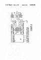
- FIG. 1is a block and schematic diagram of apparatus according to this invention useful for optimizing electrical stimulation of nerve fibers
- FIG. 2is a typical representation of bi-phased pulse pairs utilized in this invention
- FIG. 3is a block and schematic diagram of a microcomputer controlled nerve stimulator that can be used for optimizing electrical stimulation of nerve fibers;
- FIG. 4is a flow chart for the microcomputer program of the microcomputer shown in FIG. 3;
- FIG. 5is a generalized graph illustrating a single nerve fiber firing
- FIG. 6is a generalized graph illustrating the relative excitability of a neuron with respect to time after firing has occurred
- FIG. 7is a typical bell shaped curve depicting the electrical stimulation effects on a typical nerve fiber
- FIG. 8is a typical bell shaped curve depicting the cumulative effect of frequency and pulse duration on the stimulating effect shown in FIG. 7;
- FIG. 9is a block and schematic diagram of apparatus according to this invention useful for providing interleaved pulse pairs.
- FIG. 10is a typical representation of interleaved pulse pairs useful to stimulate a plurality of different types of nerve fibers.
- the apparatus and method of this inventionoptimizes electrical stimulation of selected nerve fibers, and an apparatus useful for producing the required pulse pair is shown by the generalized block diagram of FIG. 1.
- apparatus 12includes oscillator 14 that provides an input signal to one shot multivibrator 16 to trigger the multivibrator at a leading edge of the input signal from oscillator 14.
- the Q output from one shot multivibrator 16is coupled through amplifier 18 to one side of primary winding 20 of transformer 22, while the Q output from one shot multivibrator 16 is coupled as an input to one shot multivibrator 24 with a leading edge of this input signal triggering multivibrator 24.
- the Q output from one shot multivibrator 24is coupled to one shot multivibrator 26 with a trailing edge of this input signal triggering multivibrator 26.
- the output from one shot multivibrator 26is coupled through amplifier 28 to the other side of primary winding 20 of transformer 22.
- the output taken from secondary winding 30 of transformer 22is a series of pulse pairs which are coupled to electrodes 31 and 32 (as indicated in FIG. 9) for non-invasive application of the pulse pairs to the nerve fibers then selected for stimulation.
- Typical bi-phased pulse pairs useful in this invention and produced at the output (from secondary winding 30 as shown in FIG. 1)are shown in FIG. 2, with the pulses being spaced, in time, by a distance equal to that of the refractory period in order to optimize performance, as brought out more fully hereinafter.
- microcomputer 36is caused to provide positive output pulses which are coupled through switch 38 to one side of primary winding 40 of transformer 42, and is caused to provide negative output pulses which are coupled through switch 44 to the other side of primary winding 40 of transformer 42.
- a flow chart for the microcomputer program for microcomputer 36is shown in FIG. 4.
- Switches 38 and 44are controlled by analog constant current and intensity control 46, having a potentiometer 48 connected therewith, and allow switching of polarity sequences between the electrodes connected with the output from the device to thus achieve optimum stimulation under both electrodes alternately.
- the output from the deviceis coupled from secondary winding 50 to electrodes (such as electrodes 31 and 32 as shown in FIG. 9) for non-invasive application of the pulse pair to the nerve fiber then selected for stimulation.
- the bi-phased pulse pair providedoperates in the same manner as does the bi-phased pulse pair provided by the device as shown in FIG. 1, with the pulses being likewise spaced, in time, by a distance equal to that of the refractory period in order to optimize performance, as brought out more fully hereinafter.
- nerve fibersare called neurons and are contained in cable-like bundles in the nervous tissue called nerves.
- the individual nerve fiberscomprise a portion of a nerve cell extending from the nerve cell body to its end point where the activity for which that neuron is responsible is either detected by the neuron or influenced by the neuron.
- nerve fibersextend from the spinal cord as a continuous filament to the point where they interact with other tissue.
- Nerve fibersconduct information in much the same manner as does a cable, and generally carry information in binary form.
- the number of nerve pulses per unit timedetermines the degree of activity since each nerve pulse for a given nerve fiber is identical (for practical purposes) to every other pulse relayed by that fiber.
- the electrical activity of nerve fiberscan be generalized, for purposes as set forth herein, as shown in the graphs of FIGS. 5 and 6.
- a generalized graph of voltage over time of a single nerve firingis shown in FIG. 5. It should be noted that the graph is drawn with voltage increasingly negative as it is drawn upward on the graph, as is the custom in neuroscience.
- Action Potentialis the firing of the neuron caused by either natural or artificial stimulation of the nerve
- Absolute Refractory Periodis a period of time when the nerve cannot be caused to fire (i.e., to produce a second pulse), regardless of how strongly it is stimulated, and this period of time sets the upper limit on the frequency or the rate that the neuron can fire;
- Relative Refractory Periodis a period of time wherein a stronger than normal stimulus is required to fire, or excite, the nerve, with the strength or intensity of the stimulus required to stimulate the nerve fiber diminishing over time until it reaches a minimum when the fiber has reached its resting potential, and the relative refractory period can contribute to setting the upper limit of the expectation (firing) rate of the neuron, depending upon stimulus intensity.
- FIG. 6depicts a graph of the relative excitability of the A alpha motor neuron (i.e., ease with which the neuron can be stimulated to fire) with respect to time after a previous action potential (firing). It should be noted that the peak occurs at about 6 msec when the fiber is hyperexcitable (i.e., refires or produces a second action potential with the least stimulus).
- Neuronsmay be classified by their fiber diameters and the activity for which they are responsible. When so classified, six basic groups are preferably formed (other groupings are occasionally used, but this grouping is convenient for understanding the invention).
- the time length which the neuron remains within the periods graphed in FIGS. 5 and 6are different for each class of neurons.
- the fiber class, specific function, size diameter, conduction velocity (CV), refractory period time (RP), and peak hyperexcitability time (HE) for five groupsare set forth in Table I as follows:
- Nervescontain a mixture of the above-listed fibers with large numbers of each type of fiber being normally included in the nerve.
- the effect of electrical stimulationis increased by increasing the frequency with which the stimulus is able to fire the individual fibers (as noted previously) as well as increasing the total number of individual fibers of the same class which are excited simultaneously.
- This inventionutilizes the foregoing to enhance and optimize the therapeutic benefit of electrical stimulation.
- the inventionis described hereinafter with respect to application to a particular type of nerve fiber (sensory) to produce maximum sensation (i.e., to stimulate sensory neurons) and is to be considered as an example of the overall invention. Every other type of neuron is susceptible to the same factors (as set forth hereinafter) except that the time periods are different (but still specific) for each class of neuron.
- a positive pulse applied to the nerveis believed to set the nerve fibers of the sensory neurons into a condition similar to the refractory period (this pulse is important because it apparently causes a large number of fibers to be synchronized at the same time into the same state or period, thereby causing them to return to the hyperexcitability condition simultaneously);
- a positive pulse (of the next pulse pair) applied to the nerve 2500 microseconds (plus or minus 300 microseconds) after the first positive pulseis believed to again set the nerve fibers of the sensory neurons into a condition similar to the refractory period (this time interval coincides with both the maximum firing rate of a neuron and the time of peak relative excitability and establishes the maximum frequency of repetition);
- the width of the pulsesis maximized at 50 microseconds (plus or minus 15 microseconds) with the pulse shape or waveform (for example, rise time and or fall time) being unimportant, and pulse amplitude and duration being preferably the same for both the positive and negative pulses of the pulse pair with no improvement in the effect of electrical stimulation being noted when made different.
- Pulses of either positive or negative polaritycan be inserted between the paired pulses described above without varying the increased effect noted when the pulses of the pulse pair are applied in proper polarity at the proper time intervals as brought out hereinabove.
- Such additional pulsesdo not affect the increased stimulation (including the enhanced stimulation as above described) unless included close in time to the second pulse of the pulse pair, in which case they arrive during the relative refractory period and, apparently then reduce the synchronization of the fibers. This result is predictable because nerve fibers in the absolute refractory period cannot be affected by stimulus of any magnitude insufficient to damage the neuron.
- time periods as set forth above for listed factors 2 through 4are, respectively, 120 microseconds (plus or minus 20 microseconds), 2,000 microseconds (plus or minus 300 microseconds) and 50 microseconds (plus or minus 15 microseconds) for fast twitch motor nerves, and are, respectively, 1,800 microseconds (plus or minus 300 microseconds) 4,500 microseconds (plus or minus 600 microseconds) and 50 microseconds (plus or minus 15 microseconds) for pain reduction neurons.
- each class of nerve fibershas a range of fiber diameters, and since the time periods of the nerve action potential sequence is dependent upon fiber diameter, a slight modification of time between pulses by modulating the time between pulses and rate will optimally excite still more fibers in a given class of neurons.
- apparatus 54is similar to that of the apparatus shown in FIG. 1, except that the Q output of one shot multivibrator 26 is coupled through isolation diode 56 to amplifier 28, and the Q output of multivibrator 26 is coupled to one shot multivibrator 58 with a leading edge of this input signal to multivibrator 58 triggering the multivibrator.
- the Q output from one shot multivibrator 58is applied to one shot multivibrator 60 with a trailing edge of the input triggering multivibrator 60.
- the Q output of multivibrator 60is then coupled through isolation diode 62 to amplifier 28, and the input of amplifier 28 is also connected with ground through resistor 64, as indicated in FIG. 9.
- pulsesare produced at the output of the device (i.e., at secondary winding 30 which is connected with electrodes 31 and 32 as indicated in FIG. 9), which pulses constitute a plurality of pulse pairs (each of which pairs includes the positive pulse and one negative pulse) that are interleaved, as shown in FIG. 10.
- a first pulse pairconsists of the positive pulse and the first to occur negative pulse, as shown in FIG. 10, and these pulses are spaced, in time, a distance equal to the refractory period of a first preselected group of nerve fibers
- a second pulse pairconsists of the positive pulse and the second to occur negative pulse, as shown in FIG. 10, and these pulses are spaced, in time, a distance equal to the refractory period of a second preselected group of nerve fibers.
- the postive pulse and the first occurring negative pulseare separated, in time, a distance of about 120 microseconds, while the positive pulse and the second occurring negative pulse are separated, in time, a distance of about 600 microseconds to meet the refractory period spacings needed to optimize stimulation of both groups of nerve fibers.
- the device and method of this inventionhas been found to be useful in connection with human subjects.
- Thirty six normal subjects and two chronic pain patientswere studied to determine the effects of an electrical waveform which was designed to optimize the effects of stimulation on specific neuronal fibers.
- the waveformwas adjusted to apply electrical pulses of the correct polarity, timed to the refractory period of specific nerve fibers.
- Substantial increases in the effect of electrical stimulation of sensory, motor (A alpha, beta, and gamma) and pain control fibers (apparently C fibers)was noted.
- Facilitative stimulation of small diameter nerve fibershas also been demonstrated to manage pain in two patients with chronic cervical, back and head pain.
- the peaking effects for time between pulses and ratewere substantially equal to the refractory period and the maximum firing rate of the selected fibers, respectively.
- the peaking effect produced by optimum pulse widthwas extremely consistent in the experimental group and was the same independent of the nerve fiber stimulated. The reason for the peak associated with pulse width is unknown. Results were, however, consistent between individuals.
- the two chronic pain patientshave retested several times when their pain returned. During each test an effort was made to determine optimum time periods for each variable for pain relief. Thus far, these time periods appear to equal the refractory period (1.8 milliseconds) for small diameter fibers. It should be remembered that the stimulation is facilitative and since the stimulus is almost imperceptible it seems clear that the fibers stimulated are not pain fibers. After each test the pain patients report that they are virtually pain free for two to four days.
- this inventionprovides improved apparatus and method for achieving optimization of electrical stimulation of nerve fibers of the human body.
Landscapes
- Health & Medical Sciences (AREA)
- Life Sciences & Earth Sciences (AREA)
- Biomedical Technology (AREA)
- Biophysics (AREA)
- Heart & Thoracic Surgery (AREA)
- Engineering & Computer Science (AREA)
- Pain & Pain Management (AREA)
- Nuclear Medicine, Radiotherapy & Molecular Imaging (AREA)
- Radiology & Medical Imaging (AREA)
- Animal Behavior & Ethology (AREA)
- General Health & Medical Sciences (AREA)
- Public Health (AREA)
- Veterinary Medicine (AREA)
- Electrotherapy Devices (AREA)
Abstract
Description
TABLE I __________________________________________________________________________NERVE FIBER CHARACTERISTICS FIBER CLASS A alpha A beta A gamma C __________________________________________________________________________Function MOTOR MOTOR SENSORY MOTOR PAIN & FAST MEDIUM SLOW AUTONOMIC TWITCH TWITCH TWITCH SIZE DIA. 17 15 13 8 <1.3 (MICRO- METERS) CV M/SEC 80-90 60-70 50-60 10-40 .7-2.3 RP .12 MSEC .5 MSEC .6 MSEC 1.1 MSEC 1.8 MSEC HE 2 MSEC 2.5 MSEC 2.5 MSEC 4 MSEC 4.5 MSEC __________________________________________________________________________
Claims (25)
Priority Applications (2)
| Application Number | Priority Date | Filing Date | Title |
|---|---|---|---|
| US06/667,873US4640286A (en) | 1984-11-02 | 1984-11-02 | Optimized nerve fiber stimulation |
| US07/009,927US4803988A (en) | 1984-11-02 | 1987-02-02 | Nerve fiber stimulation using plural equally active electrodes |
Applications Claiming Priority (1)
| Application Number | Priority Date | Filing Date | Title |
|---|---|---|---|
| US06/667,873US4640286A (en) | 1984-11-02 | 1984-11-02 | Optimized nerve fiber stimulation |
Related Child Applications (1)
| Application Number | Title | Priority Date | Filing Date |
|---|---|---|---|
| US07/009,927Continuation-In-PartUS4803988A (en) | 1984-11-02 | 1987-02-02 | Nerve fiber stimulation using plural equally active electrodes |
Publications (1)
| Publication Number | Publication Date |
|---|---|
| US4640286Atrue US4640286A (en) | 1987-02-03 |
Family
ID=24680020
Family Applications (2)
| Application Number | Title | Priority Date | Filing Date |
|---|---|---|---|
| US06/667,873Expired - LifetimeUS4640286A (en) | 1984-11-02 | 1984-11-02 | Optimized nerve fiber stimulation |
| US07/009,927Expired - LifetimeUS4803988A (en) | 1984-11-02 | 1987-02-02 | Nerve fiber stimulation using plural equally active electrodes |
Family Applications After (1)
| Application Number | Title | Priority Date | Filing Date |
|---|---|---|---|
| US07/009,927Expired - LifetimeUS4803988A (en) | 1984-11-02 | 1987-02-02 | Nerve fiber stimulation using plural equally active electrodes |
Country Status (1)
| Country | Link |
|---|---|
| US (2) | US4640286A (en) |
Cited By (55)
| Publication number | Priority date | Publication date | Assignee | Title |
|---|---|---|---|---|
| US4813418A (en)* | 1987-02-02 | 1989-03-21 | Staodynamics, Inc. | Nerve fiber stimulation using symmetrical biphasic waveform applied through plural equally active electrodes |
| EP0414248A2 (en) | 1989-08-25 | 1991-02-27 | Staodynamics Inc. | Microprocessor controlled electronic stimulating device having biphasic pulse output |
| US4996987A (en)* | 1989-05-10 | 1991-03-05 | Therapeutic Technologies Inc. | Power muscle stimulator |
| US5036850A (en)* | 1989-08-25 | 1991-08-06 | Staodyn, Inc. | Biphasic pulse output stage for electronic stimulating device |
| US5041974A (en)* | 1988-10-26 | 1991-08-20 | Walker Judith B | Multichannel stimulator for tuned stimulation |
| US5048522A (en)* | 1990-04-13 | 1991-09-17 | Therapeutic Technologies, Inc. | Power muscle stimulator |
| US5097833A (en)* | 1989-09-19 | 1992-03-24 | Campos James M | Transcutaneous electrical nerve and/or muscle stimulator |
| US5117826A (en)* | 1987-02-02 | 1992-06-02 | Staodyn, Inc. | Combined nerve fiber and body tissue stimulation apparatus and method |
| US5350414A (en)* | 1991-12-10 | 1994-09-27 | Electro Science Technologies, Inc. | Local application microprocessor based nerve and muscle stimulator |
| US5487759A (en)* | 1993-06-14 | 1996-01-30 | Bastyr; Charles A. | Nerve stimulating device and associated support device |
| US5514165A (en)* | 1993-12-23 | 1996-05-07 | Jace Systems, Inc. | Combined high voltage pulsed current and neuromuscular stimulation electrotherapy device |
| US5782893A (en)* | 1996-02-26 | 1998-07-21 | J.D. Medical, Inc. | Neuromuscular electrical stimulator for deep vein thrombosis treatment |
| US5797854A (en)* | 1995-08-01 | 1998-08-25 | Hedgecock; James L. | Method and apparatus for testing and measuring current perception threshold and motor nerve junction performance |
| US5948007A (en)* | 1997-04-30 | 1999-09-07 | Medtronic, Inc. | Dual channel implantation neurostimulation techniques |
| US6522926B1 (en) | 2000-09-27 | 2003-02-18 | Cvrx, Inc. | Devices and methods for cardiovascular reflex control |
| US20030135245A1 (en)* | 2002-01-15 | 2003-07-17 | Bruce Douglas Rowe | Resonant muscle stimulator |
| US20040019364A1 (en)* | 2000-09-27 | 2004-01-29 | Cvrx, Inc. | Devices and methods for cardiovascular reflex control via coupled electrodes |
| US20040049241A1 (en)* | 2002-09-10 | 2004-03-11 | Therapeutic Innovations, Inc. | Distributed muscle stimulator |
| US20040116978A1 (en)* | 2002-12-06 | 2004-06-17 | Kerry Bradley | Method for determining stimulation parameters |
| US20040236386A1 (en)* | 2002-01-15 | 2004-11-25 | Therapeutic Innovations | Resonant muscle stimulator |
| US20040236385A1 (en)* | 2003-01-31 | 2004-11-25 | Therapeutic Innovations, Inc. | Rectal resonant muscle stimulator |
| US6830550B2 (en) | 2002-06-25 | 2004-12-14 | James Lee Hedgecock | Stair step voltage actuated measurement method and apparatus |
| US20040254616A1 (en)* | 2000-09-27 | 2004-12-16 | Cvrx, Inc. | Stimulus regimens for cardiovascular reflex control |
| US6850801B2 (en) | 2001-09-26 | 2005-02-01 | Cvrx, Inc. | Mapping methods for cardiovascular reflex control devices |
| US20050222644A1 (en)* | 2004-03-31 | 2005-10-06 | Cochlear Limited | Pulse burst electrical stimulation of nerve or tissue fibers |
| US20050278001A1 (en)* | 2004-06-15 | 2005-12-15 | Li Qin | Interferential and neuromuscular electrical stimulation system and apparatus |
| US20060004417A1 (en)* | 2004-06-30 | 2006-01-05 | Cvrx, Inc. | Baroreflex activation for arrhythmia treatment |
| US6985774B2 (en) | 2000-09-27 | 2006-01-10 | Cvrx, Inc. | Stimulus regimens for cardiovascular reflex control |
| US20060111626A1 (en)* | 2003-03-27 | 2006-05-25 | Cvrx, Inc. | Electrode structures having anti-inflammatory properties and methods of use |
| US20060129210A1 (en)* | 2004-11-09 | 2006-06-15 | Institut National D'optique | Device and method for transmitting multiple optically-encoded stimulation signals to multiple cell locations |
| US20060217768A1 (en)* | 2005-01-28 | 2006-09-28 | Felix Buhlmann | Independent protection system for an electrical muscle stimulation apparatus and method of using same |
| US20060265038A1 (en)* | 2005-05-19 | 2006-11-23 | Cvrx, Inc. | Implantable electrode assembly having reverse electrode configuration |
| US7158832B2 (en) | 2000-09-27 | 2007-01-02 | Cvrx, Inc. | Electrode designs and methods of use for cardiovascular reflex control devices |
| US20070021792A1 (en)* | 2000-09-27 | 2007-01-25 | Cvrx, Inc. | Baroreflex Modulation Based On Monitored Cardiovascular Parameter |
| US20070038260A1 (en)* | 2000-09-27 | 2007-02-15 | Cvrx, Inc. | Stimulation lead for stimulating the baroreceptors in the pulmonary artery |
| US20070161912A1 (en)* | 2006-01-10 | 2007-07-12 | Yunlong Zhang | Assessing autonomic activity using baroreflex analysis |
| USRE40279E1 (en) | 1997-06-26 | 2008-04-29 | Sherwood Services Ag | Method and system for neural tissue modification |
| US20080103532A1 (en)* | 2006-10-27 | 2008-05-01 | Cyberonics, Inc. | Implantable neurostimulator with refractory stimulation |
| US20080167699A1 (en)* | 2000-09-27 | 2008-07-10 | Cvrx, Inc. | Method and Apparatus for Providing Complex Tissue Stimulation Parameters |
| US20080177365A1 (en)* | 2000-09-27 | 2008-07-24 | Cvrx, Inc. | Method and apparatus for electronically switching electrode configuration |
| US20080208286A1 (en)* | 2003-10-22 | 2008-08-28 | Cvrx, Inc. | Baroreflex activation for pain control, sedation and sleep |
| US20090132002A1 (en)* | 2007-05-11 | 2009-05-21 | Cvrx, Inc. | Baroreflex activation therapy with conditional shut off |
| USRE41045E1 (en) | 1996-06-27 | 2009-12-15 | Covidien Ag | Method and apparatus for altering neural tissue function |
| US20100042180A1 (en)* | 2005-04-19 | 2010-02-18 | Compex Technologies, Inc | Electrical stimulation device and method for therapeutic treatment and pain management |
| US20100198300A1 (en)* | 2009-02-05 | 2010-08-05 | Cochlear Limited | Stimulus timing for a stimulating medical device |
| US20100249874A1 (en)* | 2000-09-27 | 2010-09-30 | Bolea Stephen L | Baroreflex therapy for disordered breathing |
| US7840271B2 (en) | 2000-09-27 | 2010-11-23 | Cvrx, Inc. | Stimulus regimens for cardiovascular reflex control |
| US8249705B1 (en) | 2007-03-20 | 2012-08-21 | Cvrx, Inc. | Devices, systems, and methods for improving left ventricular structure and function using baroreflex activation therapy |
| US8594794B2 (en) | 2007-07-24 | 2013-11-26 | Cvrx, Inc. | Baroreflex activation therapy with incrementally changing intensity |
| US8620438B1 (en) | 2007-02-13 | 2013-12-31 | Encore Medical Asset Corporation | Method and apparatus for applying neuromuscular electrical stimulation |
| US9101768B2 (en) | 2013-03-15 | 2015-08-11 | Globus Medical, Inc. | Spinal cord stimulator system |
| US9364667B1 (en) | 2014-03-31 | 2016-06-14 | Elassia LLC | Potentiating or eliciting an erotic sensation in a body using electrostimulation |
| US9872997B2 (en) | 2013-03-15 | 2018-01-23 | Globus Medical, Inc. | Spinal cord stimulator system |
| US9878170B2 (en) | 2013-03-15 | 2018-01-30 | Globus Medical, Inc. | Spinal cord stimulator system |
| US9887574B2 (en) | 2013-03-15 | 2018-02-06 | Globus Medical, Inc. | Spinal cord stimulator system |
Families Citing this family (28)
| Publication number | Priority date | Publication date | Assignee | Title |
|---|---|---|---|---|
| BR8800201A (en)* | 1988-01-21 | 1989-09-05 | Antonio Ilson Giordani | ELECTROSTIMULATOR |
| US5782873A (en)* | 1995-10-11 | 1998-07-21 | Trustees Of Boston University | Method and apparatus for improving the function of sensory cells |
| US6308102B1 (en) | 1999-09-29 | 2001-10-23 | Stimsoft, Inc. | Patient interactive neurostimulation system and method |
| US6654642B2 (en)* | 1999-09-29 | 2003-11-25 | Medtronic, Inc. | Patient interactive neurostimulation system and method |
| US7151914B2 (en) | 2001-08-21 | 2006-12-19 | Medtronic, Inc. | Transmitter system for wireless communication with implanted devices |
| US9205261B2 (en) | 2004-09-08 | 2015-12-08 | The Board Of Trustees Of The Leland Stanford Junior University | Neurostimulation methods and systems |
| US20120277839A1 (en) | 2004-09-08 | 2012-11-01 | Kramer Jeffery M | Selective stimulation to modulate the sympathetic nervous system |
| US7337005B2 (en) | 2004-09-08 | 2008-02-26 | Spinal Modulations, Inc. | Methods for stimulating a nerve root ganglion |
| US7519431B2 (en)* | 2005-04-11 | 2009-04-14 | Medtronic, Inc. | Shifting between electrode combinations in electrical stimulation device |
| US20060229687A1 (en)* | 2005-04-11 | 2006-10-12 | Medtronic, Inc. | Shifting between electrode combinations in electrical stimulation device |
| JP4873897B2 (en)* | 2005-07-29 | 2012-02-08 | 株式会社ニデック | Visual reproduction assist device |
| US20070142863A1 (en) | 2005-12-15 | 2007-06-21 | Kerry Bradley | Apparatus and methods for stimulating tissue |
| CA2671250A1 (en) | 2006-12-06 | 2008-06-12 | Spinal Modulation, Inc. | Hard tissue anchors and delivery devices |
| CA2671575A1 (en)* | 2006-12-06 | 2008-06-12 | Spinal Modulation, Inc. | Grouped leads for spinal stimulation |
| JP5414531B2 (en) | 2006-12-06 | 2014-02-12 | スパイナル・モデュレーション・インコーポレイテッド | Delivery device and systems and methods for stimulating neural tissue at multiple spinal levels |
| US9314618B2 (en)* | 2006-12-06 | 2016-04-19 | Spinal Modulation, Inc. | Implantable flexible circuit leads and methods of use |
| WO2008070808A2 (en)* | 2006-12-06 | 2008-06-12 | Spinal Modulation, Inc. | Expandable stimulation leads and methods of use |
| JP5562648B2 (en)* | 2007-01-29 | 2014-07-30 | スパイナル・モデュレーション・インコーポレイテッド | Non-stitched top retaining mechanism |
| WO2008128215A1 (en)* | 2007-04-13 | 2008-10-23 | Alejandro Covalin | Apparatus and method for the treatment of headache |
| US7742810B2 (en) | 2007-05-23 | 2010-06-22 | Boston Scientific Neuromodulation Corporation | Short duration pre-pulsing to reduce stimulation-evoked side-effects |
| EP2373378B1 (en)* | 2008-10-27 | 2017-04-26 | Spinal Modulation Inc. | Selective stimulation systems and signal parameters for medical conditions |
| AU2010204703B8 (en)* | 2009-01-14 | 2015-10-08 | Spinal Modulation, Inc. | Stimulation leads, delivery systems and methods of use |
| US8380318B2 (en) | 2009-03-24 | 2013-02-19 | Spinal Modulation, Inc. | Pain management with stimulation subthreshold to paresthesia |
| WO2010132816A2 (en)* | 2009-05-15 | 2010-11-18 | Spinal Modulation, Inc. | Methods, systems and devices for neuromodulating spinal anatomy |
| CA2798961A1 (en) | 2010-05-10 | 2011-11-17 | Spinal Modulation, Inc. | Methods, systems and devices for reducing migration |
| CN103561811A (en) | 2011-02-02 | 2014-02-05 | 脊髓调制公司 | Devices, systems and methods for the targeted treatment of movement disorders |
| WO2013086420A1 (en)* | 2011-12-07 | 2013-06-13 | Spinal Modulation, Inc. | Neuromodulation of subcellular structures within the dorsal root ganglion |
| US10792495B2 (en) | 2016-12-01 | 2020-10-06 | Thimble Bioelectronics, Inc. | Neuromodulation device and method for use |
Citations (8)
| Publication number | Priority date | Publication date | Assignee | Title |
|---|---|---|---|---|
| US2375575A (en)* | 1940-06-22 | 1945-05-08 | Morland Preben | Apparatus for treatment of nerves and muscles by means of electric impulses |
| US2498882A (en)* | 1946-06-20 | 1950-02-28 | Research Corp | Impulse stimulating apparatus |
| US3522811A (en)* | 1969-02-13 | 1970-08-04 | Medtronic Inc | Implantable nerve stimulator and method of use |
| US3946745A (en)* | 1973-03-22 | 1976-03-30 | Biopulse Company Limited | Apparatus for generating positive and negative electric pulses for application to a living body for therapeutic purposes |
| US4147171A (en)* | 1977-01-28 | 1979-04-03 | Greene Ronald W | Transcutaneous pain control and/or muscle stimulating apparatus |
| US4237899A (en)* | 1978-09-26 | 1980-12-09 | Stimtech, Inc. | Electronic tissue stimulator with output signal controls |
| US4256116A (en)* | 1978-07-03 | 1981-03-17 | Technion Research And Development Foundation, Limited | Transcutaneous pain reliever |
| US4324253A (en)* | 1977-01-28 | 1982-04-13 | Greene Ronald W | Transcutaneous pain control and/or muscle stimulating apparatus |
- 1984
- 1984-11-02USUS06/667,873patent/US4640286A/ennot_activeExpired - Lifetime
- 1987
- 1987-02-02USUS07/009,927patent/US4803988A/ennot_activeExpired - Lifetime
Patent Citations (8)
| Publication number | Priority date | Publication date | Assignee | Title |
|---|---|---|---|---|
| US2375575A (en)* | 1940-06-22 | 1945-05-08 | Morland Preben | Apparatus for treatment of nerves and muscles by means of electric impulses |
| US2498882A (en)* | 1946-06-20 | 1950-02-28 | Research Corp | Impulse stimulating apparatus |
| US3522811A (en)* | 1969-02-13 | 1970-08-04 | Medtronic Inc | Implantable nerve stimulator and method of use |
| US3946745A (en)* | 1973-03-22 | 1976-03-30 | Biopulse Company Limited | Apparatus for generating positive and negative electric pulses for application to a living body for therapeutic purposes |
| US4147171A (en)* | 1977-01-28 | 1979-04-03 | Greene Ronald W | Transcutaneous pain control and/or muscle stimulating apparatus |
| US4324253A (en)* | 1977-01-28 | 1982-04-13 | Greene Ronald W | Transcutaneous pain control and/or muscle stimulating apparatus |
| US4256116A (en)* | 1978-07-03 | 1981-03-17 | Technion Research And Development Foundation, Limited | Transcutaneous pain reliever |
| US4237899A (en)* | 1978-09-26 | 1980-12-09 | Stimtech, Inc. | Electronic tissue stimulator with output signal controls |
Non-Patent Citations (2)
| Title |
|---|
| Guyton, Basic Human Neurophysiology Third Edition, W. B. Saunders Co., 1981, pp. 26 28.* |
| Guyton, Basic Human Neurophysiology-Third Edition, W. B. Saunders Co., ©1981, pp. 26-28. |
Cited By (143)
| Publication number | Priority date | Publication date | Assignee | Title |
|---|---|---|---|---|
| US5117826A (en)* | 1987-02-02 | 1992-06-02 | Staodyn, Inc. | Combined nerve fiber and body tissue stimulation apparatus and method |
| US4813418A (en)* | 1987-02-02 | 1989-03-21 | Staodynamics, Inc. | Nerve fiber stimulation using symmetrical biphasic waveform applied through plural equally active electrodes |
| US5041974A (en)* | 1988-10-26 | 1991-08-20 | Walker Judith B | Multichannel stimulator for tuned stimulation |
| US4996987A (en)* | 1989-05-10 | 1991-03-05 | Therapeutic Technologies Inc. | Power muscle stimulator |
| US5036850A (en)* | 1989-08-25 | 1991-08-06 | Staodyn, Inc. | Biphasic pulse output stage for electronic stimulating device |
| EP0414248A2 (en) | 1989-08-25 | 1991-02-27 | Staodynamics Inc. | Microprocessor controlled electronic stimulating device having biphasic pulse output |
| US5069211A (en)* | 1989-08-25 | 1991-12-03 | Staodyn, Inc. | Microprocessor controlled electronic stimulating device having biphasic pulse output |
| US5097833A (en)* | 1989-09-19 | 1992-03-24 | Campos James M | Transcutaneous electrical nerve and/or muscle stimulator |
| US5048522A (en)* | 1990-04-13 | 1991-09-17 | Therapeutic Technologies, Inc. | Power muscle stimulator |
| US5350414A (en)* | 1991-12-10 | 1994-09-27 | Electro Science Technologies, Inc. | Local application microprocessor based nerve and muscle stimulator |
| US5487759A (en)* | 1993-06-14 | 1996-01-30 | Bastyr; Charles A. | Nerve stimulating device and associated support device |
| US5514165A (en)* | 1993-12-23 | 1996-05-07 | Jace Systems, Inc. | Combined high voltage pulsed current and neuromuscular stimulation electrotherapy device |
| US5797854A (en)* | 1995-08-01 | 1998-08-25 | Hedgecock; James L. | Method and apparatus for testing and measuring current perception threshold and motor nerve junction performance |
| US5782893A (en)* | 1996-02-26 | 1998-07-21 | J.D. Medical, Inc. | Neuromuscular electrical stimulator for deep vein thrombosis treatment |
| USRE41045E1 (en) | 1996-06-27 | 2009-12-15 | Covidien Ag | Method and apparatus for altering neural tissue function |
| US5948007A (en)* | 1997-04-30 | 1999-09-07 | Medtronic, Inc. | Dual channel implantation neurostimulation techniques |
| US6122548A (en)* | 1997-04-30 | 2000-09-19 | Medtronic, Inc. | System and method for preventing cross-conduction in a human-implantable dual channel neurostimulator |
| USRE40279E1 (en) | 1997-06-26 | 2008-04-29 | Sherwood Services Ag | Method and system for neural tissue modification |
| US20080167694A1 (en)* | 2000-09-27 | 2008-07-10 | Cvrx, Inc. | Automatic neural stimulation based on activity |
| US8583236B2 (en) | 2000-09-27 | 2013-11-12 | Cvrx, Inc. | Devices and methods for cardiovascular reflex control |
| US6522926B1 (en) | 2000-09-27 | 2003-02-18 | Cvrx, Inc. | Devices and methods for cardiovascular reflex control |
| US7623926B2 (en) | 2000-09-27 | 2009-11-24 | Cvrx, Inc. | Stimulus regimens for cardiovascular reflex control |
| US7616997B2 (en) | 2000-09-27 | 2009-11-10 | Kieval Robert S | Devices and methods for cardiovascular reflex control via coupled electrodes |
| US20100179614A1 (en)* | 2000-09-27 | 2010-07-15 | Kieval Robert S | Devices and methods for cardiovascular reflex control |
| US20040254616A1 (en)* | 2000-09-27 | 2004-12-16 | Cvrx, Inc. | Stimulus regimens for cardiovascular reflex control |
| US20090234418A1 (en)* | 2000-09-27 | 2009-09-17 | Kieval Robert S | Devices and methods for cardiovascular reflex control via coupled electrodes |
| US9427583B2 (en) | 2000-09-27 | 2016-08-30 | Cvrx, Inc. | Electrode structures and methods for their use in cardiovascular reflex control |
| US9044609B2 (en) | 2000-09-27 | 2015-06-02 | Cvrx, Inc. | Electrode structures and methods for their use in cardiovascular reflex control |
| US8880190B2 (en) | 2000-09-27 | 2014-11-04 | Cvrx, Inc. | Electrode structures and methods for their use in cardiovascular reflex control |
| US6985774B2 (en) | 2000-09-27 | 2006-01-10 | Cvrx, Inc. | Stimulus regimens for cardiovascular reflex control |
| US20100191303A1 (en)* | 2000-09-27 | 2010-07-29 | Cvrx, Inc. | Automatic baroreflex modulation responsive to adverse event |
| US7801614B2 (en) | 2000-09-27 | 2010-09-21 | Cvrx, Inc. | Stimulus regimens for cardiovascular reflex control |
| US8838246B2 (en) | 2000-09-27 | 2014-09-16 | Cvrx, Inc. | Devices and methods for cardiovascular reflex treatments |
| US8718789B2 (en) | 2000-09-27 | 2014-05-06 | Cvrx, Inc. | Electrode structures and methods for their use in cardiovascular reflex control |
| US8712531B2 (en) | 2000-09-27 | 2014-04-29 | Cvrx, Inc. | Automatic baroreflex modulation responsive to adverse event |
| US7158832B2 (en) | 2000-09-27 | 2007-01-02 | Cvrx, Inc. | Electrode designs and methods of use for cardiovascular reflex control devices |
| US20070021792A1 (en)* | 2000-09-27 | 2007-01-25 | Cvrx, Inc. | Baroreflex Modulation Based On Monitored Cardiovascular Parameter |
| US20070021794A1 (en)* | 2000-09-27 | 2007-01-25 | Cvrx, Inc. | Baroreflex Therapy for Disordered Breathing |
| US20070021797A1 (en)* | 2000-09-27 | 2007-01-25 | Cvrx, Inc. | Baroreflex stimulation synchronized to circadian rhythm |
| US20070021796A1 (en)* | 2000-09-27 | 2007-01-25 | Cvrx, Inc. | Baroreflex modulation to gradually decrease blood pressure |
| US20070021799A1 (en)* | 2000-09-27 | 2007-01-25 | Cvrx, Inc. | Automatic baroreflex modulation based on cardiac activity |
| US20100249874A1 (en)* | 2000-09-27 | 2010-09-30 | Bolea Stephen L | Baroreflex therapy for disordered breathing |
| US20070038260A1 (en)* | 2000-09-27 | 2007-02-15 | Cvrx, Inc. | Stimulation lead for stimulating the baroreceptors in the pulmonary artery |
| US20070038259A1 (en)* | 2000-09-27 | 2007-02-15 | Cvrx, Inc. | Method and apparatus for stimulation of baroreceptors in pulmonary artery |
| US20070038262A1 (en)* | 2000-09-27 | 2007-02-15 | Cvrx, Inc. | Baroreflex stimulation system to reduce hypertension |
| US20070038261A1 (en)* | 2000-09-27 | 2007-02-15 | Cvrx, Inc. | Lead for stimulating the baroreceptors in the pulmonary artery |
| US20070060972A1 (en)* | 2000-09-27 | 2007-03-15 | Cvrx, Inc. | Devices and methods for cardiovascular reflex treatments |
| US20080215111A1 (en)* | 2000-09-27 | 2008-09-04 | Cvrx, Inc. | Devices and Methods for Cardiovascular Reflex Control |
| US8606359B2 (en) | 2000-09-27 | 2013-12-10 | Cvrx, Inc. | System and method for sustained baroreflex stimulation |
| US7813812B2 (en) | 2000-09-27 | 2010-10-12 | Cvrx, Inc. | Baroreflex stimulator with integrated pressure sensor |
| US20070167984A1 (en)* | 2000-09-27 | 2007-07-19 | Cvrx, Inc. | Method and apparatus for stimulation of baroreceptors |
| US20080177364A1 (en)* | 2000-09-27 | 2008-07-24 | Cvrx, Inc. | Self-locking electrode assembly usable with an implantable medical device |
| US20070185543A1 (en)* | 2000-09-27 | 2007-08-09 | Cvrx, Inc. | System and method for sustained baroreflex stimulation |
| US8290595B2 (en) | 2000-09-27 | 2012-10-16 | Cvrx, Inc. | Method and apparatus for stimulation of baroreceptors in pulmonary artery |
| US8086314B1 (en) | 2000-09-27 | 2011-12-27 | Cvrx, Inc. | Devices and methods for cardiovascular reflex control |
| US20080177348A1 (en)* | 2000-09-27 | 2008-07-24 | Cvrx, Inc. | Electrode contact configurations for an implantable stimulator |
| US20040019364A1 (en)* | 2000-09-27 | 2004-01-29 | Cvrx, Inc. | Devices and methods for cardiovascular reflex control via coupled electrodes |
| US8060206B2 (en) | 2000-09-27 | 2011-11-15 | Cvrx, Inc. | Baroreflex modulation to gradually decrease blood pressure |
| US7949400B2 (en) | 2000-09-27 | 2011-05-24 | Cvrx, Inc. | Devices and methods for cardiovascular reflex control via coupled electrodes |
| US7840271B2 (en) | 2000-09-27 | 2010-11-23 | Cvrx, Inc. | Stimulus regimens for cardiovascular reflex control |
| US20100174347A1 (en)* | 2000-09-27 | 2010-07-08 | Kieval Robert S | Devices and methods for cardiovascular reflex control via coupled electrodes |
| US20080167699A1 (en)* | 2000-09-27 | 2008-07-10 | Cvrx, Inc. | Method and Apparatus for Providing Complex Tissue Stimulation Parameters |
| US20080172101A1 (en)* | 2000-09-27 | 2008-07-17 | Cvrx, Inc. | Non-linear electrode array |
| US20080177339A1 (en)* | 2000-09-27 | 2008-07-24 | Cvrx, Inc. | Electrode contact configurations for cuff leads |
| US20080177365A1 (en)* | 2000-09-27 | 2008-07-24 | Cvrx, Inc. | Method and apparatus for electronically switching electrode configuration |
| US20080177349A1 (en)* | 2000-09-27 | 2008-07-24 | Cvrx, Inc. | Apparatus and method for modulating the baroreflex system |
| US20080177366A1 (en)* | 2000-09-27 | 2008-07-24 | Cvrx, Inc. | Cuff electrode arrangement for nerve stimulation and methods of treating disorders |
| US20070106340A1 (en)* | 2001-09-26 | 2007-05-10 | Cvrx, Inc. | Electrode structures and methods for their use in cardiovascular reflex control |
| US20080097540A1 (en)* | 2001-09-26 | 2008-04-24 | Cvrx, Inc. | Ecg input to implantable pulse generator using carotid sinus leads |
| US6850801B2 (en) | 2001-09-26 | 2005-02-01 | Cvrx, Inc. | Mapping methods for cardiovascular reflex control devices |
| US7593775B2 (en) | 2002-01-15 | 2009-09-22 | Therapeutic Innovations | Sports equipment with resonant muscle stimulator for developing muscle strength |
| US20030135245A1 (en)* | 2002-01-15 | 2003-07-17 | Bruce Douglas Rowe | Resonant muscle stimulator |
| US7035691B2 (en) | 2002-01-15 | 2006-04-25 | Therapeutic Innovations, Inc. | Resonant muscle stimulator |
| US7254447B2 (en) | 2002-01-15 | 2007-08-07 | Therapeutic Innovations, Inc. | Resonant muscle stimulator |
| US20040236386A1 (en)* | 2002-01-15 | 2004-11-25 | Therapeutic Innovations | Resonant muscle stimulator |
| US6830550B2 (en) | 2002-06-25 | 2004-12-14 | James Lee Hedgecock | Stair step voltage actuated measurement method and apparatus |
| US20040049241A1 (en)* | 2002-09-10 | 2004-03-11 | Therapeutic Innovations, Inc. | Distributed muscle stimulator |
| US7174215B2 (en) | 2002-12-06 | 2007-02-06 | Advanced Bionics Corporation | Method for determining stimulation parameters |
| US20040116978A1 (en)* | 2002-12-06 | 2004-06-17 | Kerry Bradley | Method for determining stimulation parameters |
| US20040236385A1 (en)* | 2003-01-31 | 2004-11-25 | Therapeutic Innovations, Inc. | Rectal resonant muscle stimulator |
| US20060111626A1 (en)* | 2003-03-27 | 2006-05-25 | Cvrx, Inc. | Electrode structures having anti-inflammatory properties and methods of use |
| US20080208286A1 (en)* | 2003-10-22 | 2008-08-28 | Cvrx, Inc. | Baroreflex activation for pain control, sedation and sleep |
| US8224437B2 (en) | 2003-10-22 | 2012-07-17 | Cvrx, Inc. | Baroreflex activation for sedation and sleep |
| US8478414B2 (en) | 2003-10-22 | 2013-07-02 | Cvrx, Inc. | Baroreflex activation for pain control, sedation and sleep |
| US8560076B2 (en) | 2003-10-22 | 2013-10-15 | Cvrx, Inc. | Devices and methods for electrode implantation |
| US20110137374A1 (en)* | 2003-10-22 | 2011-06-09 | Kieval Robert S | Devices and methods for electrode implantation |
| US8755907B2 (en) | 2003-10-22 | 2014-06-17 | Cvrx, Inc. | Devices and methods for electrode implantation |
| US20080177354A1 (en)* | 2004-03-31 | 2008-07-24 | Cochlear Limited | Pulse burst electrical stimulation of nerve or tissue fibers |
| US20050222644A1 (en)* | 2004-03-31 | 2005-10-06 | Cochlear Limited | Pulse burst electrical stimulation of nerve or tissue fibers |
| US7333858B2 (en)* | 2004-03-31 | 2008-02-19 | Cochlear Limited | Pulse burst electrical stimulation of nerve or tissue fibers |
| US20050278001A1 (en)* | 2004-06-15 | 2005-12-15 | Li Qin | Interferential and neuromuscular electrical stimulation system and apparatus |
| US7613518B2 (en) | 2004-06-15 | 2009-11-03 | Encore Medical Asset Corporation | Interferential and neuromuscular electrical stimulation system and apparatus |
| US20060004417A1 (en)* | 2004-06-30 | 2006-01-05 | Cvrx, Inc. | Baroreflex activation for arrhythmia treatment |
| US20070156198A1 (en)* | 2004-06-30 | 2007-07-05 | Cvrx, Inc. | Coordinated therapy for disordered breathing including baroreflex modulation |
| US20090198294A1 (en)* | 2004-06-30 | 2009-08-06 | Rossing Martin A | Baroreflex activation for arrhythmia treatment |
| US20060129210A1 (en)* | 2004-11-09 | 2006-06-15 | Institut National D'optique | Device and method for transmitting multiple optically-encoded stimulation signals to multiple cell locations |
| US7883535B2 (en) | 2004-11-09 | 2011-02-08 | Institut National D'optique | Device and method for transmitting multiple optically-encoded stimulation signals to multiple cell locations |
| US8140165B2 (en) | 2005-01-28 | 2012-03-20 | Encore Medical Asset Corporation | Independent protection system for an electrical muscle stimulation apparatus and method of using same |
| US9808619B2 (en) | 2005-01-28 | 2017-11-07 | Encore Medical Asset Corporation | Independent protection system for an electrical muscle stimulation apparatus and method of using same |
| US20060217768A1 (en)* | 2005-01-28 | 2006-09-28 | Felix Buhlmann | Independent protection system for an electrical muscle stimulation apparatus and method of using same |
| US10328260B2 (en) | 2005-04-19 | 2019-06-25 | Djo, Llc | Electrical stimulation device and method for therapeutic treatment and pain management |
| US9669212B2 (en) | 2005-04-19 | 2017-06-06 | Djo, Llc | Electrical stimulation device and method for therapeutic treatment and pain management |
| US8958883B2 (en) | 2005-04-19 | 2015-02-17 | Pierre-Yves Mueller | Electrical stimulation device and method for therapeutic treatment and pain management |
| US20100042180A1 (en)* | 2005-04-19 | 2010-02-18 | Compex Technologies, Inc | Electrical stimulation device and method for therapeutic treatment and pain management |
| US20060265038A1 (en)* | 2005-05-19 | 2006-11-23 | Cvrx, Inc. | Implantable electrode assembly having reverse electrode configuration |
| US7395119B2 (en) | 2005-05-19 | 2008-07-01 | Cvrx, Inc. | Implantable electrode assembly having reverse electrode configuration |
| US20070276442A1 (en)* | 2005-05-19 | 2007-11-29 | Cvrx, Inc. | Implantable electrode assembly having reverse electrode configuration |
| US20080140167A1 (en)* | 2005-05-19 | 2008-06-12 | Cvrx, Inc. | Implantable electrode assembly having reverse electrode configuration |
| US20090069738A1 (en)* | 2005-12-29 | 2009-03-12 | Cvrx, Inc. | Electrode Structures Having Anti-Inflammatory Properties And Methods Of Use |
| US20070161912A1 (en)* | 2006-01-10 | 2007-07-12 | Yunlong Zhang | Assessing autonomic activity using baroreflex analysis |
| US8109879B2 (en) | 2006-01-10 | 2012-02-07 | Cardiac Pacemakers, Inc. | Assessing autonomic activity using baroreflex analysis |
| US9949668B2 (en) | 2006-01-10 | 2018-04-24 | Cardiac Pacemakers, Inc. | Assessing autonomic activity using baroreflex analysis |
| US7869867B2 (en)* | 2006-10-27 | 2011-01-11 | Cyberonics, Inc. | Implantable neurostimulator with refractory stimulation |
| US20080103532A1 (en)* | 2006-10-27 | 2008-05-01 | Cyberonics, Inc. | Implantable neurostimulator with refractory stimulation |
| US8620438B1 (en) | 2007-02-13 | 2013-12-31 | Encore Medical Asset Corporation | Method and apparatus for applying neuromuscular electrical stimulation |
| US9669211B2 (en) | 2007-02-13 | 2017-06-06 | Encore Medical Asset Corporation | Method and apparatus for applying neuromuscular electrical stimulation |
| US9352151B2 (en) | 2007-02-13 | 2016-05-31 | Encore Medical Asset Corporation | Method and apparatus for applying neuromuscular electrical stimulation |
| US8249705B1 (en) | 2007-03-20 | 2012-08-21 | Cvrx, Inc. | Devices, systems, and methods for improving left ventricular structure and function using baroreflex activation therapy |
| US20090132002A1 (en)* | 2007-05-11 | 2009-05-21 | Cvrx, Inc. | Baroreflex activation therapy with conditional shut off |
| US8594794B2 (en) | 2007-07-24 | 2013-11-26 | Cvrx, Inc. | Baroreflex activation therapy with incrementally changing intensity |
| US20100198300A1 (en)* | 2009-02-05 | 2010-08-05 | Cochlear Limited | Stimulus timing for a stimulating medical device |
| US9339648B2 (en) | 2009-02-05 | 2016-05-17 | Cochlear Limited | Stimulus timing for a stimulating medical device |
| US8688222B2 (en) | 2009-02-05 | 2014-04-01 | Cochlear Limited | Stimulus timing for a stimulating medical device |
| US9713715B2 (en) | 2009-02-05 | 2017-07-25 | Cochlear Limited | Stimulus timing for a stimulating medical device |
| US9878170B2 (en) | 2013-03-15 | 2018-01-30 | Globus Medical, Inc. | Spinal cord stimulator system |
| US9101768B2 (en) | 2013-03-15 | 2015-08-11 | Globus Medical, Inc. | Spinal cord stimulator system |
| US9623246B2 (en) | 2013-03-15 | 2017-04-18 | Globus Medical, Inc. | Spinal cord stimulator system |
| US9550062B2 (en) | 2013-03-15 | 2017-01-24 | Globus Medical, Inc | Spinal cord stimulator system |
| US9308369B2 (en) | 2013-03-15 | 2016-04-12 | Globus Medical, Inc. | Spinal cord stimulator system |
| US9872997B2 (en) | 2013-03-15 | 2018-01-23 | Globus Medical, Inc. | Spinal cord stimulator system |
| US9872986B2 (en) | 2013-03-15 | 2018-01-23 | Globus Medical, Inc. | Spinal cord stimulator system |
| US9440076B2 (en) | 2013-03-15 | 2016-09-13 | Globus Medical, Inc. | Spinal cord stimulator system |
| US9887574B2 (en) | 2013-03-15 | 2018-02-06 | Globus Medical, Inc. | Spinal cord stimulator system |
| US11704688B2 (en) | 2013-03-15 | 2023-07-18 | Cirtec Medical Corp. | Spinal cord stimulator system |
| US9956409B2 (en) | 2013-03-15 | 2018-05-01 | Globus Medical, Inc. | Spinal cord stimulator system |
| US10016602B2 (en) | 2013-03-15 | 2018-07-10 | Globus Medical, Inc. | Spinal cord stimulator system |
| US10016605B2 (en) | 2013-03-15 | 2018-07-10 | Globus Medical, Inc. | Spinal cord stimulator system |
| US10149977B2 (en) | 2013-03-15 | 2018-12-11 | Cirtec Medical Corp. | Spinal cord stimulator system |
| US10265526B2 (en) | 2013-03-15 | 2019-04-23 | Cirtec Medical Corp. | Spinal cord stimulator system |
| US9492665B2 (en) | 2013-03-15 | 2016-11-15 | Globus Medical, Inc. | Spinal cord stimulator system |
| US10335597B2 (en) | 2013-03-15 | 2019-07-02 | Cirtec Medical Corp. | Spinal cord stimulator system |
| US10810614B2 (en) | 2013-03-15 | 2020-10-20 | Cirtec Medical Corp. | Spinal cord stimulator system |
| US9364667B1 (en) | 2014-03-31 | 2016-06-14 | Elassia LLC | Potentiating or eliciting an erotic sensation in a body using electrostimulation |
Also Published As
| Publication number | Publication date |
|---|---|
| US4803988A (en) | 1989-02-14 |
Similar Documents
| Publication | Publication Date | Title |
|---|---|---|
| US4640286A (en) | Optimized nerve fiber stimulation | |
| US4813418A (en) | Nerve fiber stimulation using symmetrical biphasic waveform applied through plural equally active electrodes | |
| US5117826A (en) | Combined nerve fiber and body tissue stimulation apparatus and method | |
| US3650275A (en) | Method and apparatus for controlling anal incontinence | |
| US8868204B2 (en) | Esthetic device useful for increasing skin beautification and methods thereof | |
| US6671557B1 (en) | System and method for providing percutaneous electrical therapy | |
| US5193537A (en) | Method and apparatus for transcutaneous electrical cardiac pacing | |
| US4509521A (en) | Headache relief method | |
| US4637397A (en) | Triphasic wave defibrillation | |
| US5282843A (en) | Electrodes and method for transcutaneous cardiac pacing | |
| US4535777A (en) | Method of providing electrical stimulation of tissue | |
| US5447526A (en) | Transcutaneous electric muscle/nerve controller/feedback unit | |
| EP0103490A2 (en) | Exercising apparatus | |
| DE4425546A1 (en) | Transcutaneous pacemaker | |
| EP0594620A4 (en) | Method and apparatus for transcutaneous cardiac pacing. | |
| Fang et al. | Alternate excitation of large and small axons with different stimulation waveforms: an application to muscle activation | |
| CA1313539C (en) | Nerve fiber stimulation using plural equally active electrodes | |
| US6633778B2 (en) | High-energy, high-frequency pulse defibrillator | |
| CA1287879C (en) | Optimized nerve fiber stimulation | |
| US4830009A (en) | Method for electrical stimulation, more particularly for the treatment of scoliosis | |
| Bhadra et al. | High-frequency nerve conduction block | |
| Balogun | Pain complaint and muscle soreness associated with high-voltage electrical stimulation: effect of ramp time | |
| Anastasijević et al. | Renshaw cell discharge at the beginning of muscular contraction and its relation to the silent period | |
| GB2324965A (en) | A muscle restructuring system | |
| CA1261401A (en) | Relieving headaches by application of specific electric pulses |
Legal Events
| Date | Code | Title | Description |
|---|---|---|---|
| AS | Assignment | Owner name:STAODYNAMICS, INC., 1225 FLORIDA AVE., LONGMONT, Free format text:ASSIGNMENT OF ASSIGNORS INTEREST.;ASSIGNOR:THOMSON, THOMAS H.;REEL/FRAME:004332/0971 Effective date:19841102 | |
| STCF | Information on status: patent grant | Free format text:PATENTED CASE | |
| FPAY | Fee payment | Year of fee payment:4 | |
| FPAY | Fee payment | Year of fee payment:8 | |
| REMI | Maintenance fee reminder mailed | ||
| FPAY | Fee payment | Year of fee payment:12 | |
| SULP | Surcharge for late payment | ||
| AS | Assignment | Owner name:U.S. BANK NATIONAL ASSOCIATION, MINNESOTA Free format text:SECURITY INTEREST;ASSIGNOR:REHABILICARE INC.;REEL/FRAME:010133/0219 Effective date:19990714 | |
| AS | Assignment | Owner name:STAODYNAMICS, INC., COLORADO Free format text:CORRECTIVE ASSIGNMENT TO CORRECTLY RECORD ASSIGNMENT PREVIOUSLY RECORDED AT REEL 4332 FRAME 0971;ASSIGNOR:THOMSON, THOMAS H.;REEL/FRAME:011682/0125 Effective date:19841102 Owner name:STAODYNAMICS, INC. A DELAWARE CORPORATION, COLORAD Free format text:MERGER;ASSIGNOR:STAODYNAMICS, INC. A COLORADO CORPORATION;REEL/FRAME:011682/0164 Effective date:19870923 Owner name:STAODYN, INC., COLORADO Free format text:CHANGE OF NAME;ASSIGNOR:STAODYNAMICS, INC., A DELAWARE CORPORATION;REEL/FRAME:011682/0168 Effective date:19900831 Owner name:REHABILLICARE, INC., MINNESOTA Free format text:NUNC PRO TUNC ASSIGNMENT EFFECTIVE DATE 3/18/98.;ASSIGNOR:STAODYN, INC.;REEL/FRAME:011682/0185 Effective date:20010329 | |
| AS | Assignment | Owner name:COMPEX TECHNOLOGIES, INC. AS SUCCESSOR IN INTEREST Free format text:RELEASE BY SECURED PARTY;ASSIGNOR:U.S. BANK NATIONAL ASSOCIATION;REEL/FRAME:018224/0963 Effective date:20060227 |