US4639772A - Focusable video camera for use with endoscopes - Google Patents
Focusable video camera for use with endoscopesDownload PDFInfo
- Publication number
- US4639772A US4639772AUS06/578,274US57827484AUS4639772AUS 4639772 AUS4639772 AUS 4639772AUS 57827484 AUS57827484 AUS 57827484AUS 4639772 AUS4639772 AUS 4639772A
- Authority
- US
- United States
- Prior art keywords
- optical
- cylindrical body
- endoscope
- optical system
- cover
- Prior art date
- Legal status (The legal status is an assumption and is not a legal conclusion. Google has not performed a legal analysis and makes no representation as to the accuracy of the status listed.)
- Expired - Fee Related
Links
Images


Classifications
- A—HUMAN NECESSITIES
- A61—MEDICAL OR VETERINARY SCIENCE; HYGIENE
- A61B—DIAGNOSIS; SURGERY; IDENTIFICATION
- A61B1/00—Instruments for performing medical examinations of the interior of cavities or tubes of the body by visual or photographical inspection, e.g. endoscopes; Illuminating arrangements therefor
- A61B1/04—Instruments for performing medical examinations of the interior of cavities or tubes of the body by visual or photographical inspection, e.g. endoscopes; Illuminating arrangements therefor combined with photographic or television appliances
- A61B1/042—Instruments for performing medical examinations of the interior of cavities or tubes of the body by visual or photographical inspection, e.g. endoscopes; Illuminating arrangements therefor combined with photographic or television appliances characterised by a proximal camera, e.g. a CCD camera
- H—ELECTRICITY
- H04—ELECTRIC COMMUNICATION TECHNIQUE
- H04N—PICTORIAL COMMUNICATION, e.g. TELEVISION
- H04N23/00—Cameras or camera modules comprising electronic image sensors; Control thereof
- H04N23/50—Constructional details
- H04N23/55—Optical parts specially adapted for electronic image sensors; Mounting thereof
- H—ELECTRICITY
- H10—SEMICONDUCTOR DEVICES; ELECTRIC SOLID-STATE DEVICES NOT OTHERWISE PROVIDED FOR
- H10F—INORGANIC SEMICONDUCTOR DEVICES SENSITIVE TO INFRARED RADIATION, LIGHT, ELECTROMAGNETIC RADIATION OF SHORTER WAVELENGTH OR CORPUSCULAR RADIATION
- H10F39/00—Integrated devices, or assemblies of multiple devices, comprising at least one element covered by group H10F30/00, e.g. radiation detectors comprising photodiode arrays
- H10F39/80—Constructional details of image sensors
- H10F39/804—Containers or encapsulations
- A—HUMAN NECESSITIES
- A61—MEDICAL OR VETERINARY SCIENCE; HYGIENE
- A61B—DIAGNOSIS; SURGERY; IDENTIFICATION
- A61B1/00—Instruments for performing medical examinations of the interior of cavities or tubes of the body by visual or photographical inspection, e.g. endoscopes; Illuminating arrangements therefor
- A61B1/00163—Optical arrangements
- A61B1/00188—Optical arrangements with focusing or zooming features
Definitions
- This inventionrelates to video cameras for use in conjunction with endoscopes in medical and surgical applications.
- the inventionrelates to video cameras which are or may be attached to the end of the endoscope operated by medical personnel where an image from a selected area inside a patient's body cavity is produced external to the endoscope.
- Endoscopeshave established a wide variety of utility in the medical and surgical fields for viewing inside the human body.
- endoscopesare useful in the surgical specialties of arthroscopy, bronchoscopy, colonoscopy, cystoscopy, gastroscopy, laparoscopy, laryngoscopy, sigmoidoscopy, microsurgery, neurosurgery, colposcopy, ophthalmology/corneal surgery with microscope, ophthalmology/vitreous surgery with microscope, and ophthalmology/indirect examination and general surgery.
- the forward end of an endoscopeis placed in the body cavity where viewing is desired.
- An illumination meansis provided either as part of the endoscope or by a separate means.
- the endoscope endsenses imagery in the cavity and transmits that imagery, typically by means of a fiber optic bundle to an output means at the end of the endoscope outside the body.
- the light signals delivered at the output end of the endoscopeare then employed in a variety of ways, such as by direct viewing or through beam splitting by both direct viewing and to a camera for television viewing or by television viewing alone. Where it is desired to televise the endoscopy, the features desired in the camera are complex due to the large performance differences in different types of endoscopes, the reduced light transmission of endoscopes with age, the wide variety of light sources, the variation of type of cavity into which the endoscope may be inserted, and the need for ease of handling and light weight to facilitate use.
- Light transmissionis a key variable among endoscopes.
- the type and size of endoscopegreatly affects the amount of light transmitted from a subject to the television camera. For example, larger glass fiber bundles yield more light, hence, a brighter image which is easier to televise.
- the outside diameter of endoscopes of the same typemay be an indication of the size of the glass fiber bundle. In general, shorter and larger diameter endoscopes transfer more light than longer or smaller diameter instruments.
- Operating endoscopesusually have smaller light transmission bundles than diagnostic types to permit channels for instruments, air, and/or water. Thus, it is usually easier to televise imagery from diagnostic endoscopes than from operating endoscopes, given the same medical circumstances.
- a common endoscopy problemis the dramatic reduction in image intensity resulting when the endoscope moves from a small body passage into a much larger cavity.
- a distance from the endoscope tip to the subjectfor example, up to 20 millimeters.
- the subject distancemay increase, for example, up to 100 millimeters or greater.
- the light on the subjectis reduced by the inverse square of the subject distance to about 4 percent of the light available at 20 millimeters.
- the relative angle of the tissue to be viewedmay change, altering the reflectivity of the surface.
- small diameter cavitiesoften act as a reflector directing light forward toward the viewing area.
- a 12-inch television monitoris satisfactory for viewing video endoscopy.
- the size of the image on a particular monitoris determined by the magnification of the endoscope. Image size as a percentage of screen height is important from the standpoint of brightness and resolution. As the image is enlarged to full screen height, the image resolution will increase because more video scanning lines are utilized. However, image brightness decreases as a function of the square of image size. With constant illumination and no light change, a 40 percent larger image will be 50 percent less bright.
- a number of video cameras for endoscopyhave been available.
- a color television endoscope camerais made by Circon Corporation, Model MV 9330/35. This camera weighs 6 ounces and employs a pick up tube two-thirds of an inch in length.
- Circon Corporationhas had available various optical accessories, including couplers, eye piece adapters, and beam splitters.
- the resulting video systemis sufficiently small and light that it can be mounted directly on any rigid or flexible endoscope. Since the color television camera receives a direct image from the endoscope, its image brightness, color fidelity, and resolution are superior to larger size cameras, which must be connected to an endoscope through articulated lenses or fiber optic links.
- Such linkscan cause image rotation and waste valuable image intensity, thereby interfering with the endoscopy process.
- an optical coupleris normally employed for the interface of a video camera to an endoscope.
- the couplerconnects the camera directly to the endoscope.
- all the available lightgoes directly into the camera, permitting the brightest possible television image.
- an adapter ringto the endoscope for easily removing the video camera or the beam splitter when used, thus providing direct viewing to the endoscope.
- This camerais 11/2 inches in diameter by 51/2 inches long and weighs also six ounces. Its unique light sensitivity is particularly advantageous in televising very difficult microsurgery.
- the above-described devicesare employed first by use of an adapter fixed to the end of the endoscope which receives an optical coupler having therein an optical system for passing the image to the camera. At the end of the coupler, a camera is attached.
- the coupler-and-camera combinationreceives optical imagery from the output end of the endoscope and converts it to preprocessed color video signals which are then transmitted for processing and projection on a color television monitor.
- the method of the present invention for manufacturing a video camera for use in conjunction with an endoscopeprovides for forming a hollow body and enclosing within the body an optical system for receiving and transmitting optical imagery from an endoscope and placing around the outside of the optical system, but within the same body, electronic circuitry for preprocessing video signals received from a sensor-converter located within the body and behind the optical system.
- the apparatus of the inventionis that resulting from the foregoing method.
- FIG. 1is a diagram of a video system which employs the invention
- FIG. 2is a perspective view of the outside of the camera of the present invention along with an adapter for facilitating attachment to an endoscope;
- FIG. 3is a lengthwise section view through the optical axis of the optical system, along line 3--3 of FIG. 4;
- FIG. 4is a sectional view through line 4--4 of FIG. 3;
- FIG. 5is the electronic circuit of the camera
- FIG. 6is a sectional view of an alternative embodiment of the invention.
- FIG. 7is a sectional view of yet another embodiment of the invention.
- FIG. 8is an elevation view of the embodiment of FIG. 7;
- FIG. 9is a front sectional view of an alternate embodiment of a endoscope camera using the teachings of this invention.
- FIG. 10is a top plan view of of the video endoscopes showing the video processing means
- FIG. 11is a front plan view of another embodiment of a video camera having a bayonet type receiving means.
- FIG. 12is a right end elevational view showing the bayonet type receiving means of FIG. 11.
- FIG. 1shows a general diagram of an endoscope video system comprising the output end of an endoscope 1, an adapter 2 for connecting the endoscope 1 to an optical system 3, a solid state sensor-converter 4 which receives light from the optical system 3 and converts it in a known manner to electronic signals capable of being further processed for video display, the sensor-converter 4 being connected to driver-preamplifiers of the preprocessing electronics 5, whose output signals are transmitted to the processing electronics 6, and finally the video signals are transmitted to the video monitor 7.
- the subject of the present inventioncan be fully described.
- FIG. 2there is shown an external view of the camera 8 on the present invention comprising a body 9 and, attached to it, an adapter 2 for attaching the camera 8 to an endoscope.
- the adapter 2is of a conventional known design.
- a cable 10is shown extending from the most rearward portion of the body 9 and will normally extend to a video processing system for processing and projecting video signals onto a video monitor or for recording on a video recorder.
- the endoscope video camera of the present inventionis made up of the body 9 shown generally at 9, which is adapted for containing and having mounted therein the various components of the camera.
- the body 9has a main cylinder portion 11 which defines a cavity 12, in which are mounted the three subsystems of the camera, namely, the optical lens system 14, the sensor-converter 16, and the preprocessing electronics 18.
- the body 9has a forward end 20 which has an aperture 22.
- the aperture 22is sealed and covered by a window 24.
- the optical lens system 14is aligned behind the aperture 22 and is illustrated by lenses 26 and 28, defining an optical axis 32.
- the window 24 and simple lenses 26 and 28are here illustrated, a more complex system, including one in which the window 24 would be used as a lens, could be employed in a manner known to those skilled in the art.
- the sensor-converter 16has a receiving surface 34 which is a self-scanning solid state imaging device, such as a charge coupled device (CCD) or a MOS device located in the image plane of the lens system 14, and mounted in a slightly enlarged, cylindrical portion 30, of the body 9, rearward of the main cylinder portion 11.
- a charge coupled deviceCCD
- MOSmetal-oxide-semiconductor
- the specific construction and operation of such a MOS imageris known to those skilled in the art and is exemplified by the Hitachi Model HE 98221.
- the preprocessing electronics 18are operatively connected, in a known manner, to the sensor-converter 16.
- the preprocessing electronics 18include four integrated circuit packages 36, one to process each of the color signals--yellow, white, green, and cyan. Such integrated circuits are well known in the art.
- the integrated circuit packages 36are mounted on printing wiring substrates 38 which are arranged around the outside of the lens system 14, extending inside the main cylinder portion 11 and mounted to the body 9.
- the printed wiring substrate 38is made in a known manner according to the required circuit from flexible, plastic material.
- the printed wiring substrate 38may be configured in a number of variations in order to extend around the lens system 14.
- FIG. 4two separate substrates, which could be relatively rigid with a flexed or bent corner portion, are shown. Also, the substrate could be one piece of flexible-type circuit positioned around the lens system with flat areas upon which the integrated circuit packages 36 are mounted.
- a substructuresuch as illustrated at 40, be placed beneath the substrate.
- material known as "fishpaper" folded into a generally square shapemay be employed.
- the printed wiring substrate 38rests inside the body 9 upon a shoulder inside the cavity 12 where additional mounting means may be employed to retain the circuit in a fixed position.
- Rear enclosure 42closes the rear of the body 9.
- Rear enclosure 42has an aperture 44 through which cable 10 sealably passes.
- the cable 10carries wires operatively attached to the electronic means within the body carrying video signals to a color video processor at a remote location and thereafter to a video monitor and includes means for providing power to operate the internal electronics.
- a sealing meansillustrated in FIG. 6 as a circular ring seal, such as an O-ring, seals the rear enclosure 42, where it attaches to the cylindrical portion 11.
- the forward end 20may be formed as a separate sealable cover, similarly employing a sealing means as illustrated in FIG. 6, by an O-ring seal. Use of a separate sealably attachable forward end 20 and rear enclosure 42 is preferred for simplicity of manufacture of the body 9.
- the optics and electronicsare carried in a single-body portion in a very compact manner so that the optics and preprocessing electronics reside in the same part of the body, effecting dual use of that part of the body and eliminating the need for separate parts. Also, this combined optical and electronic camera structure is easily sealable to be soakable in disinfectant for medical purposes, which is accomplished by the sealable features of both the rear enclosure 42 and the forward end 20 which is more fully described with reference to FIG. 6.
- the electronic circuit of the camerais converter 16 and the integrated circuits 36. Where component values are shown in FIG. 5, capacitor values are in microfarads and resisters in thousand ohms, except as otherwise noted.
- the circuit of the four integrated circuits 36are the same, one of them being shown in detail.
- the camera of the present inventionhas placed on its front end an adapter 2, of known design, as shown in FIG. 1, which is then attached in a known manner to the receiving end of an endoscope or, alternatively, to the receiving end of a beam splitter, which is attached to the receiving end of the endoscope.
- optical imagery transmitted through the endoscope to its output endpasses through the window 24 and is transmitted through the optical lens system 14 to impinge upon the receiving CCD grid pattern of the sensor-converter 16.
- Electrical signals from the sensor-converter 16are transmitted through appropriate wiring to the preprocessing electronics 18 and thereafter through interconnected wiring to the cable 10 to connect to a color video system in a remote location.
- the sensor-converter 16is activated and controlled by means of interconnections through the cable 10 and from the preprocessing electronics 18.
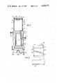
- FIG. 6An alternative embodiment of the invention is shown in FIG. 6, which includes all the advantages of the invention as previously described but has the additional feature that the optical system is focusable.
- the body 100is formed of two parts.
- the first body portion 102is a cylinder which retains a forward portion 104, which has in it an optical aperture 106.
- the forward portion 104is sealably attached to the first body portion 102 by means of seal 108.
- a forward portion of the optical system 110is attached to the first body portion 102, aligned with the optical aperture 106 defining an optical axis 112.
- the aperture 106is covered by a window 113, which could also be part of the optical system.
- a rearward second body portion 114is also in the form of a cylinder and retains the rear closure 116, sealed by means of the seal 118.
- the first body portion 102is telescoped inside the second body portion 114.
- a rear portion 120 of the optical systemMounted inside the second body portion 114 is a rear portion 120 of the optical system.
- the sensor-converter 122 and the preprocessing electronics 124are shown mounted in and are connected in the second body portion 114 in a manner similar to that hereinbefore described.
- On the outer periphery of the cylindrical first body portion 102is a thread 126, and on the inner periphery of the second body portion 114 is a thread 128, the threads 126 and 128 being interengageable so that relative rotation of the first body portion 102 and the second body portion 114 will cause relative movement of the forward portion 110 and the rearward portion 120 of the optical system to accomplish focusing.
- the telescoped cylindrical parts of the body portions 102 and 114should be sized for close but freely movable fit.
- a groove 130, in the first body portion 102contains an O-ring seal 132.
- a set screw 134 in a threaded hole 136acts to retain the two body portions in position to maintain the focus of the optical system.
- This alternative embodimentoperates in the same manner as previously explained. However, it provides the additional feature of focusing the image at the image plane.
- the sensing base of the sensor-converter 122is preferably located at the image plane.
- FIGS. 7 and 8Another alternative embodiment of the invention is shown in FIGS. 7 and 8.
- this embodimentis a focusable version where focusing is achieved by a groove or slot, to form a camway, and a follower.
- the body 200is formed of two parts.
- the first body portion 202is a cylinder which retains a forward portion 204 which has in it an optical aperture 206.
- the forward portion 204is sealably attached to the first body portion 202 by means of a seal 208.
- a forward portion of the optical system 210is attached to the first body portion 202, aligned with the optical aperture 206 defining an optical axis 212.
- the aperture 206is covered by a window 213, which could also be part of the optical system.
- the window 213is sealably fitted by an O-ring 211.
- a rearward second body portion 214is also in the form of a cylinder and retains the rear closure 216 sealed by means of the seal 218.
- the first body portion 202is telescoped inside the second body portion 214 and is sealed by means of O-rings 215 in grooves 217.
- the sensor-converter 222 and the preprocessing electronics 224are shown mounted in and are connected in the second body portion 214 in a manner similar to that hereinbefore described.
- On the outer periphery of the cylindrical first body portion 202is a threaded hole 226.
- Through the wall of the second body portionis a groove or slot 228.
- a follower 230is screwed into the hole 226 and extends into the slot 228. In order to facilitate assembly and disassembly, the follower 230 is made long enough so that it protrudes outside the second body portion 214 and, therefore, it can be easily turned by hand or a simple tool.
- the screw 230can bear against the outer surface of the second body portion 214 to fix the relative position of the two body portions and, thus, the two portions of the optical system 210 and 220.
- Another position fixing meansis shown as set screw 232 in threaded hole 234.
- the groove or slot 228is set at a pitch relative to the optical axis 212, and is of such length around the second body portion 214 to provide the extent of forward and rearward motion as is required by the optical system and the particular application for focusing.
- the seals 215are placed to avoid passage of fluid during soaking into the cavity formed by the body portions.
- FIG. 9illustrates an alternative embodiment of an endoscope camera using the teachings of this invention.
- the bodyis shown generally as 300.
- the cylindrical body 302has a cavity 303 which is adapted to receive a top member 304 and a bottom member 306.
- Top member 304includes an annular slot 308 which is adapted to sealingly receive an O-ring 310.
- the top member 304includes a thin-walled, elongated, cylindrically shaped, tubular member 312 which extends a predetermined length into the cavity 303.
- the top member 304includes a threaded hole 309 for accepting extended locking member 311.
- the interior sidewall 314 of the tubular member 312has located near its termination in the cavity at 316 internal threads 318. At its termination in the cavity, there is located on the exterior sidewall of the tubular member 312 a pair of opposed elongated finger-like supports 320 for spacing the end 316 from a solid-state imaging device 322 which is attached by fasteners 324 through spacer 326 to the supports 320.
- the bottom member 306includes a recessed area 330 which accommodates the electrical conductors 332 from cable 334.
- the bottom member 306likewise includes an annular slot 340 for receiving a sealing O-ring 342.
- an assembly formed of two concentric cylinder-shaped members 350 and 352 which are formed of copper and Delrin, respectively, installed concentrically on tubular member 312are part of a video processing means and are utilized for supporting the video processing electronics shown generally as 354. The details of the assembly comprising the video processing means is shown in FIG. 10.
- the central area of the tubular member 312provides an optical path for an optical image which is to be focused on the sensing face 360 of the solid-state imaging device 322.
- the solid-state imaging device 323is an MOS sensor.
- An adapter membershown generally by 370, includes a circular top member 372, having a recess 373 to define an optical aperture.
- a transparent element 375is fitted in recess 374.
- An optical system 386formed of achromatic lens element 390 and 392, is adapted to pass an optical image from an endoscope (not shown) which enters through window 374, along the optical path and defining an optical axis 382.
- the tubular member 370includes an annular slot 400 which receives an O-ring 402 which is adapted to sealingly, slidingly move on the interior wall 314 of the elongated tubular member 312.
- the interior end 406 of elongated member 370has threads 412 formed on the exterior wall of elongated member 378.
- the threads 412are adapted to coact with threads 318 when the adapter 370 is inserted into the body 300.
- the threads 412 and 318cooperate and coact with each other to enable relative rotatable movement between adapter 370 and body 300 such that the focal plane of the optical system 386 can be adjusted as illustrated diagramatically by focal plane lines 420, 422 and 424, within the body 300.
- the adapter 370is rotatingly mounted within the body 300 and rotatable therewith to focus the optical image, located at the focal plane, onto the imaging surface 360 of the solid-state imaging device 322.
- FIG. 10shows in section that the body 302 is cylindrical in shape with the bottom member 306 being rectangular in shape.
- the video processing meansinclude the copper cylindrically shaped member 350 and a Delrin cylindrically shaped member 352, concentrically mounted thereon and concentrically mounted on the tubular member 312 to form an inner copper conductive support member and Delrin insulating member.
- the Delrin insulating memberhas a plurality of apertures or slots formed therein through which elongated conductive terminals 430 extend from the copper member 350.
- Integrated circuit devices, shown generally 434are mounted in the assembly along with other electrical components, shown generally as 436, and are electrically connected to each other and to the elongated conductive terminals 350 in a correct circuit manner.
- the preprocessing electronic circuitis arranged around the periphery of the focusable optical system, and continued in the same body portion as the optical system, forward of the solid-state imaging device.
- FIG. 11 and FIG. 12illustrate yet another embodiment for practicing the invention.
- the adapter top member 502is shown attached to the body, shown generally as 500.
- the top member 502includes a bayonet-type swivel which enables the endoscope camera to be attached to an endoscope having a bayonet receiving means.
- the remaining portion of the body 500 and its contentsare generally of the construction discussed hereinbefore.
- the conducting means or transmitting meansmay be a radio frequency telemetering system having an appropriate power source, transmitting means and receiving means. Such a system would eliminate the need of a cable.
- the endoscope conveying the optical image to the video cameracould be fabricated such that the end of the endoscope could be directly affixed to or operatively adjacent to the surface of the solid-state imaging device inside the body of the camera.
- An alternative position of the end of the endoscopewould be to locate the end thereof at the outside end of the adapter at the point of a coupling plane between the endoscope and adapter or, if so designed, spaced from the end of the adapter.
- optical systemcan have a folded optic path having a single or multiple prism or include some other similar type of optical deflecting or splitting means located along the optical path.
- FIG. 9is merely exemplary and one configuration of the optical path.
Landscapes
- Health & Medical Sciences (AREA)
- Life Sciences & Earth Sciences (AREA)
- Surgery (AREA)
- Engineering & Computer Science (AREA)
- Radiology & Medical Imaging (AREA)
- Heart & Thoracic Surgery (AREA)
- Biophysics (AREA)
- Nuclear Medicine, Radiotherapy & Molecular Imaging (AREA)
- Optics & Photonics (AREA)
- Pathology (AREA)
- Signal Processing (AREA)
- Multimedia (AREA)
- Biomedical Technology (AREA)
- Physics & Mathematics (AREA)
- Medical Informatics (AREA)
- Molecular Biology (AREA)
- Animal Behavior & Ethology (AREA)
- General Health & Medical Sciences (AREA)
- Public Health (AREA)
- Veterinary Medicine (AREA)
- Endoscopes (AREA)
Abstract
Description
Claims (3)
Priority Applications (1)
| Application Number | Priority Date | Filing Date | Title |
|---|---|---|---|
| US06/578,274US4639772A (en) | 1984-02-07 | 1984-02-07 | Focusable video camera for use with endoscopes |
Applications Claiming Priority (1)
| Application Number | Priority Date | Filing Date | Title |
|---|---|---|---|
| US06/578,274US4639772A (en) | 1984-02-07 | 1984-02-07 | Focusable video camera for use with endoscopes |
Publications (1)
| Publication Number | Publication Date |
|---|---|
| US4639772Atrue US4639772A (en) | 1987-01-27 |
Family
ID=24312152
Family Applications (1)
| Application Number | Title | Priority Date | Filing Date |
|---|---|---|---|
| US06/578,274Expired - Fee RelatedUS4639772A (en) | 1984-02-07 | 1984-02-07 | Focusable video camera for use with endoscopes |
Country Status (1)
| Country | Link |
|---|---|
| US (1) | US4639772A (en) |
Cited By (53)
| Publication number | Priority date | Publication date | Assignee | Title |
|---|---|---|---|---|
| US4722000A (en)* | 1986-10-01 | 1988-01-26 | Medical Concepts Incorporated | Adapter for endoscopic camera |
| WO1988007694A1 (en)* | 1987-03-31 | 1988-10-06 | Norbert Lemke | Lens mount for a zoom lens for television cameras |
| US4779130A (en)* | 1985-01-14 | 1988-10-18 | Olympus Optical Co., Ltd. | Endoscope having a solid-state image sensor and shield therefor |
| US4788596A (en)* | 1985-04-26 | 1988-11-29 | Canon Kabushiki Kaisha | Image stabilizing device |
| US4797737A (en)* | 1986-11-19 | 1989-01-10 | Olympus Optical Co., Ltd. | Imaging apparatus for endoscope |
| US4803557A (en)* | 1988-01-11 | 1989-02-07 | Eastman Kodak Company | Adjustable mount for image sensor |
| US4807594A (en)* | 1988-01-15 | 1989-02-28 | Medical Concepts, Incorporated | Adapter assembly for endoscopic video camera |
| US4816819A (en)* | 1984-11-26 | 1989-03-28 | Canon Kabushiki Kaisha | Display panel |
| US4818983A (en)* | 1985-08-20 | 1989-04-04 | Hamamatsu Photonics Kabushiki Kaisha | Optical image generator having a spatial light modulator and a display device |
| US4831456A (en)* | 1986-12-08 | 1989-05-16 | Olympus Optical Co., Ltd. | Imaging apparatus using a solid-state imaging element having a substrate |
| US4839723A (en)* | 1986-05-15 | 1989-06-13 | Olympus Optical Co., Ltd. | TV camera |
| US4844071A (en)* | 1988-03-31 | 1989-07-04 | Baxter Travenol Laboratories, Inc. | Endoscope coupler device |
| US4855838A (en)* | 1988-05-27 | 1989-08-08 | Cues, Inc. | Remotely controlled pan and tilt television camera |
| EP0343558A1 (en)* | 1988-05-23 | 1989-11-29 | Sumitomo Electric Industries, Ltd. | Image picking-up and processing apparatus |
| US4918517A (en)* | 1989-01-26 | 1990-04-17 | Westinghouse Electric Corp. | System and process for video monitoring a welding operation |
| US4963962A (en)* | 1989-01-25 | 1990-10-16 | Visual Methods, Inc. | Optical surveillance assembly and camera |
| WO1990013254A1 (en)* | 1989-05-05 | 1990-11-15 | Aesculap Ag | Coupling for an electronic camera and for an optical fibre waveguide |
| EP0478113A3 (en)* | 1990-09-24 | 1992-05-13 | Burle Technologies, Inc. | Environmentally sealed camera housing |
| US5124797A (en)* | 1990-07-20 | 1992-06-23 | New Image Industries, Inc. | Modular view lens attachment for micro video imaging camera |
| US5125394A (en)* | 1990-12-03 | 1992-06-30 | Medical Concepts, Inc. | Endoscopic adapter with lamina interface |
| FR2684459A1 (en)* | 1991-11-29 | 1993-06-04 | Barras Provence | Device for remote-control of the focusing and aiming of a micro-camera |
| US5350355A (en)* | 1992-02-14 | 1994-09-27 | Automated Medical Instruments, Inc. | Automated surgical instrument |
| US5521632A (en)* | 1994-06-15 | 1996-05-28 | Simon, Jr.; John O. | Adaptor for use in video microscope systems |
| US5575757A (en)* | 1992-10-09 | 1996-11-19 | Smith & Nephew Endoscopy Inc. | Endoscope with focusing mechanism |
| US5626595A (en)* | 1992-02-14 | 1997-05-06 | Automated Medical Instruments, Inc. | Automated surgical instrument |
| US5790307A (en)* | 1994-04-13 | 1998-08-04 | Carl Zeiss Stiftung | Stereotactic adapter and procedure for its use |
| US5797836A (en)* | 1995-06-07 | 1998-08-25 | Smith & Nephew, Inc. | Endoscope with relative rotation and axial motion between an optical element and an imaging device |
| US5808813A (en)* | 1996-10-30 | 1998-09-15 | Smith & Nephew, Inc. | Optical coupler |
| US6069651A (en)* | 1995-04-20 | 2000-05-30 | Olympus Optical Co., Ltd. | Imaging apparatus for endoscopes |
| US6201880B1 (en) | 1996-12-31 | 2001-03-13 | Electro-Optical Sciences | Method and apparatus for electronically imaging a tooth through transillumination by light |
| US20010036363A1 (en)* | 1999-10-01 | 2001-11-01 | Norihiko Shimose | Electronic camera |
| US20020095068A1 (en)* | 1998-07-30 | 2002-07-18 | Lubowski David Z. | Sigmoidoscope |
| US20020115908A1 (en)* | 2000-06-30 | 2002-08-22 | Inner Vision Imaging, L.L.C. | Endoscope |
| US6450949B1 (en) | 2000-06-30 | 2002-09-17 | Inner Vision Imaging, Inc. | Endoscope |
| US20030025826A1 (en)* | 2000-03-10 | 2003-02-06 | Olympus Optical Co., Ltd. | Small image pickup module |
| US20030076410A1 (en)* | 2001-10-24 | 2003-04-24 | Richard Beutter | Powered optical coupler and endoscopic viewing system using same |
| WO2004098395A1 (en)* | 2003-05-09 | 2004-11-18 | Daltray Pty Ltd | Improved sigmoidoscope with integral obturator |
| US20050151872A1 (en)* | 2004-01-08 | 2005-07-14 | Roger Kuo | Lens module for digital image-capturing device |
| KR100595716B1 (en)* | 1999-12-30 | 2006-07-03 | 엘지전자 주식회사 | Focusing Device for Solid State Imaging Device Camera |
| US7092031B1 (en)* | 1999-07-30 | 2006-08-15 | Zoran Corporation | Digital camera imaging module |
| US7129978B1 (en) | 1998-07-13 | 2006-10-31 | Zoran Corporation | Method and architecture for an improved CMOS color image sensor |
| WO2006136208A1 (en)* | 2005-06-17 | 2006-12-28 | Robert Bosch Gmbh | Camera arrangement with an image sensor sealed from environmental influences |
| US7176446B1 (en) | 1999-09-15 | 2007-02-13 | Zoran Corporation | Method and apparatus for distributing light onto electronic image sensors |
| US20070088196A1 (en)* | 2004-06-16 | 2007-04-19 | Olympus Corporation | Camera head for endoscope, camera system for endoscope, and endoscope system |
| US20070153386A1 (en)* | 2004-08-23 | 2007-07-05 | Olympus Corporation | Observation system |
| US20110313252A1 (en)* | 2010-06-18 | 2011-12-22 | Pioneer Medical Instrument Co., Ltd. | Micro sensing apparatus |
| US20120120490A1 (en)* | 2006-12-29 | 2012-05-17 | Cognex Corporation | Manually Adjustable Ruggedized Focus Mechanism |
| USD676544S1 (en)* | 2009-12-22 | 2013-02-19 | Karl Storz Gmbh & Co. Kg | Suction pipe |
| US8840543B2 (en) | 2011-12-07 | 2014-09-23 | Stryker Corporation | Parfocal coupler for endoscopic viewing system |
| US20150124070A1 (en)* | 2013-11-01 | 2015-05-07 | Srinivas Dutt | Eyepiece adapter for recording and transmitting images |
| US20190121118A1 (en)* | 2010-10-28 | 2019-04-25 | Endochoice Innovation Center Ltd. | Optical systems for multi-sensor endoscopes |
| US11887502B2 (en) | 2018-01-04 | 2024-01-30 | Applied Medical Resources Corporation | Surgical simulation camera scope |
| US12204087B2 (en)* | 2010-10-28 | 2025-01-21 | Endochoice, Inc. | Optical systems for multi-sensor endoscopes |
Citations (11)
| Publication number | Priority date | Publication date | Assignee | Title |
|---|---|---|---|---|
| US3499107A (en)* | 1954-03-11 | 1970-03-03 | Sheldon Edward E | Light transfer devices using light conducting members of multilayered construction and photoelectric means |
| US3520587A (en)* | 1967-03-29 | 1970-07-14 | Olympus Optical Co | Stereoscopic endoscope |
| US3809908A (en)* | 1973-06-29 | 1974-05-07 | Itt | Electro-optical transmission line |
| US4281910A (en)* | 1979-04-02 | 1981-08-04 | Olympus Optical Co., Ltd. | Camera apparatus for endoscope |
| JPS57105731A (en)* | 1980-12-24 | 1982-07-01 | Olympus Optical Co Ltd | Self-processing camera for endoscope |
| JPS57108839A (en)* | 1980-12-25 | 1982-07-07 | Olympus Optical Co Ltd | Endoscope photographic device |
| US4344092A (en)* | 1980-10-21 | 1982-08-10 | Circon Corporation | Miniature video camera means for video system |
| JPS57176027A (en)* | 1981-04-22 | 1982-10-29 | Olympus Optical Co Ltd | Self-processing camera for endoscope |
| US4414608A (en)* | 1980-08-07 | 1983-11-08 | Olympus Optical Co., Ltd. | Endoscope with adapter |
| US4473841A (en)* | 1981-10-20 | 1984-09-25 | Fuji Photo Film Co., Ltd. | Video signal transmission system for endoscope using solid state image sensor |
| US4491865A (en)* | 1982-09-29 | 1985-01-01 | Welch Allyn, Inc. | Image sensor assembly |
- 1984
- 1984-02-07USUS06/578,274patent/US4639772A/ennot_activeExpired - Fee Related
Patent Citations (11)
| Publication number | Priority date | Publication date | Assignee | Title |
|---|---|---|---|---|
| US3499107A (en)* | 1954-03-11 | 1970-03-03 | Sheldon Edward E | Light transfer devices using light conducting members of multilayered construction and photoelectric means |
| US3520587A (en)* | 1967-03-29 | 1970-07-14 | Olympus Optical Co | Stereoscopic endoscope |
| US3809908A (en)* | 1973-06-29 | 1974-05-07 | Itt | Electro-optical transmission line |
| US4281910A (en)* | 1979-04-02 | 1981-08-04 | Olympus Optical Co., Ltd. | Camera apparatus for endoscope |
| US4414608A (en)* | 1980-08-07 | 1983-11-08 | Olympus Optical Co., Ltd. | Endoscope with adapter |
| US4344092A (en)* | 1980-10-21 | 1982-08-10 | Circon Corporation | Miniature video camera means for video system |
| JPS57105731A (en)* | 1980-12-24 | 1982-07-01 | Olympus Optical Co Ltd | Self-processing camera for endoscope |
| JPS57108839A (en)* | 1980-12-25 | 1982-07-07 | Olympus Optical Co Ltd | Endoscope photographic device |
| JPS57176027A (en)* | 1981-04-22 | 1982-10-29 | Olympus Optical Co Ltd | Self-processing camera for endoscope |
| US4473841A (en)* | 1981-10-20 | 1984-09-25 | Fuji Photo Film Co., Ltd. | Video signal transmission system for endoscope using solid state image sensor |
| US4491865A (en)* | 1982-09-29 | 1985-01-01 | Welch Allyn, Inc. | Image sensor assembly |
Cited By (68)
| Publication number | Priority date | Publication date | Assignee | Title |
|---|---|---|---|---|
| US4816819A (en)* | 1984-11-26 | 1989-03-28 | Canon Kabushiki Kaisha | Display panel |
| US4779130A (en)* | 1985-01-14 | 1988-10-18 | Olympus Optical Co., Ltd. | Endoscope having a solid-state image sensor and shield therefor |
| US4788596A (en)* | 1985-04-26 | 1988-11-29 | Canon Kabushiki Kaisha | Image stabilizing device |
| US4818983A (en)* | 1985-08-20 | 1989-04-04 | Hamamatsu Photonics Kabushiki Kaisha | Optical image generator having a spatial light modulator and a display device |
| US4839723A (en)* | 1986-05-15 | 1989-06-13 | Olympus Optical Co., Ltd. | TV camera |
| US4722000A (en)* | 1986-10-01 | 1988-01-26 | Medical Concepts Incorporated | Adapter for endoscopic camera |
| US4797737A (en)* | 1986-11-19 | 1989-01-10 | Olympus Optical Co., Ltd. | Imaging apparatus for endoscope |
| US4831456A (en)* | 1986-12-08 | 1989-05-16 | Olympus Optical Co., Ltd. | Imaging apparatus using a solid-state imaging element having a substrate |
| WO1988007694A1 (en)* | 1987-03-31 | 1988-10-06 | Norbert Lemke | Lens mount for a zoom lens for television cameras |
| US4934789A (en)* | 1987-03-31 | 1990-06-19 | Norbert Lemke | Lens mounting for a varifocal lens for TV cameras |
| US4803557A (en)* | 1988-01-11 | 1989-02-07 | Eastman Kodak Company | Adjustable mount for image sensor |
| US4807594A (en)* | 1988-01-15 | 1989-02-28 | Medical Concepts, Incorporated | Adapter assembly for endoscopic video camera |
| US4844071A (en)* | 1988-03-31 | 1989-07-04 | Baxter Travenol Laboratories, Inc. | Endoscope coupler device |
| EP0343558A1 (en)* | 1988-05-23 | 1989-11-29 | Sumitomo Electric Industries, Ltd. | Image picking-up and processing apparatus |
| US4947245A (en)* | 1988-05-23 | 1990-08-07 | Sumitomo Electric Industries, Ltd. | Image picking-up and processing apparatus |
| US4855838A (en)* | 1988-05-27 | 1989-08-08 | Cues, Inc. | Remotely controlled pan and tilt television camera |
| US4963962A (en)* | 1989-01-25 | 1990-10-16 | Visual Methods, Inc. | Optical surveillance assembly and camera |
| US4918517A (en)* | 1989-01-26 | 1990-04-17 | Westinghouse Electric Corp. | System and process for video monitoring a welding operation |
| WO1990013254A1 (en)* | 1989-05-05 | 1990-11-15 | Aesculap Ag | Coupling for an electronic camera and for an optical fibre waveguide |
| US5124797A (en)* | 1990-07-20 | 1992-06-23 | New Image Industries, Inc. | Modular view lens attachment for micro video imaging camera |
| EP0478113A3 (en)* | 1990-09-24 | 1992-05-13 | Burle Technologies, Inc. | Environmentally sealed camera housing |
| US5125394A (en)* | 1990-12-03 | 1992-06-30 | Medical Concepts, Inc. | Endoscopic adapter with lamina interface |
| FR2684459A1 (en)* | 1991-11-29 | 1993-06-04 | Barras Provence | Device for remote-control of the focusing and aiming of a micro-camera |
| US5632758A (en)* | 1992-02-14 | 1997-05-27 | Automated Medical Instruments, Inc. | Automated surgical instrument |
| US5626595A (en)* | 1992-02-14 | 1997-05-06 | Automated Medical Instruments, Inc. | Automated surgical instrument |
| US5350355A (en)* | 1992-02-14 | 1994-09-27 | Automated Medical Instruments, Inc. | Automated surgical instrument |
| US5575757A (en)* | 1992-10-09 | 1996-11-19 | Smith & Nephew Endoscopy Inc. | Endoscope with focusing mechanism |
| US5790307A (en)* | 1994-04-13 | 1998-08-04 | Carl Zeiss Stiftung | Stereotactic adapter and procedure for its use |
| US5521632A (en)* | 1994-06-15 | 1996-05-28 | Simon, Jr.; John O. | Adaptor for use in video microscope systems |
| US6069651A (en)* | 1995-04-20 | 2000-05-30 | Olympus Optical Co., Ltd. | Imaging apparatus for endoscopes |
| US5797836A (en)* | 1995-06-07 | 1998-08-25 | Smith & Nephew, Inc. | Endoscope with relative rotation and axial motion between an optical element and an imaging device |
| US5808813A (en)* | 1996-10-30 | 1998-09-15 | Smith & Nephew, Inc. | Optical coupler |
| US6201880B1 (en) | 1996-12-31 | 2001-03-13 | Electro-Optical Sciences | Method and apparatus for electronically imaging a tooth through transillumination by light |
| US7129978B1 (en) | 1998-07-13 | 2006-10-31 | Zoran Corporation | Method and architecture for an improved CMOS color image sensor |
| US20020095068A1 (en)* | 1998-07-30 | 2002-07-18 | Lubowski David Z. | Sigmoidoscope |
| US7244228B2 (en) | 1998-07-30 | 2007-07-17 | Lubowski David Z | Sigmoidoscope |
| US7092031B1 (en)* | 1999-07-30 | 2006-08-15 | Zoran Corporation | Digital camera imaging module |
| US7176446B1 (en) | 1999-09-15 | 2007-02-13 | Zoran Corporation | Method and apparatus for distributing light onto electronic image sensors |
| US20010036363A1 (en)* | 1999-10-01 | 2001-11-01 | Norihiko Shimose | Electronic camera |
| US6842193B2 (en)* | 1999-10-01 | 2005-01-11 | Matsushita Electric Industrial Co., Ltd. | Electronic camera |
| KR100595716B1 (en)* | 1999-12-30 | 2006-07-03 | 엘지전자 주식회사 | Focusing Device for Solid State Imaging Device Camera |
| US20030025826A1 (en)* | 2000-03-10 | 2003-02-06 | Olympus Optical Co., Ltd. | Small image pickup module |
| US6679839B2 (en) | 2000-06-30 | 2004-01-20 | Inner Vision Imaging, Llc | Endoscope |
| US20040097790A1 (en)* | 2000-06-30 | 2004-05-20 | Inner Vision Imaging, L.L.C. | Endoscope |
| US6530882B1 (en) | 2000-06-30 | 2003-03-11 | Inner Vision Imaging, L.L.C. | Endoscope having microscopic and macroscopic magnification |
| US6949069B2 (en) | 2000-06-30 | 2005-09-27 | Inner Vision Imaging, L.L.C. | Endoscope |
| US20020115908A1 (en)* | 2000-06-30 | 2002-08-22 | Inner Vision Imaging, L.L.C. | Endoscope |
| US6450949B1 (en) | 2000-06-30 | 2002-09-17 | Inner Vision Imaging, Inc. | Endoscope |
| US20030076410A1 (en)* | 2001-10-24 | 2003-04-24 | Richard Beutter | Powered optical coupler and endoscopic viewing system using same |
| US6919914B2 (en) | 2001-10-24 | 2005-07-19 | Stryker Corporation | Powered optical coupler and endoscopic viewing system using same |
| WO2004098395A1 (en)* | 2003-05-09 | 2004-11-18 | Daltray Pty Ltd | Improved sigmoidoscope with integral obturator |
| US20050151872A1 (en)* | 2004-01-08 | 2005-07-14 | Roger Kuo | Lens module for digital image-capturing device |
| US7959558B2 (en) | 2004-06-16 | 2011-06-14 | Olympus Corporation | Camera head for endoscope, camera system for endoscope, and endoscope system |
| US20070088196A1 (en)* | 2004-06-16 | 2007-04-19 | Olympus Corporation | Camera head for endoscope, camera system for endoscope, and endoscope system |
| EP1767138A4 (en)* | 2004-06-16 | 2008-07-09 | Olympus Corp | Camera head for endoscope, camera system for endoscope, and endoscope system |
| US20070153386A1 (en)* | 2004-08-23 | 2007-07-05 | Olympus Corporation | Observation system |
| WO2006136208A1 (en)* | 2005-06-17 | 2006-12-28 | Robert Bosch Gmbh | Camera arrangement with an image sensor sealed from environmental influences |
| DE102005028144B4 (en) | 2005-06-17 | 2022-01-13 | Robert Bosch Gmbh | Camera arrangement with image sensor sealing against environmental influences |
| US20120120490A1 (en)* | 2006-12-29 | 2012-05-17 | Cognex Corporation | Manually Adjustable Ruggedized Focus Mechanism |
| US9039208B2 (en)* | 2006-12-29 | 2015-05-26 | Cognex Corporation | Manually adjustable ruggedized focus mechanism |
| USD676544S1 (en)* | 2009-12-22 | 2013-02-19 | Karl Storz Gmbh & Co. Kg | Suction pipe |
| US20110313252A1 (en)* | 2010-06-18 | 2011-12-22 | Pioneer Medical Instrument Co., Ltd. | Micro sensing apparatus |
| US20190121118A1 (en)* | 2010-10-28 | 2019-04-25 | Endochoice Innovation Center Ltd. | Optical systems for multi-sensor endoscopes |
| US11543646B2 (en)* | 2010-10-28 | 2023-01-03 | Endochoice, Inc. | Optical systems for multi-sensor endoscopes |
| US12204087B2 (en)* | 2010-10-28 | 2025-01-21 | Endochoice, Inc. | Optical systems for multi-sensor endoscopes |
| US8840543B2 (en) | 2011-12-07 | 2014-09-23 | Stryker Corporation | Parfocal coupler for endoscopic viewing system |
| US20150124070A1 (en)* | 2013-11-01 | 2015-05-07 | Srinivas Dutt | Eyepiece adapter for recording and transmitting images |
| US11887502B2 (en) | 2018-01-04 | 2024-01-30 | Applied Medical Resources Corporation | Surgical simulation camera scope |
Similar Documents
| Publication | Publication Date | Title |
|---|---|---|
| US4639772A (en) | Focusable video camera for use with endoscopes | |
| US4600940A (en) | Video camera for use with an endoscope and method for making same | |
| US5594497A (en) | Endoscope provided with a distally located color CCD | |
| EP1423042B1 (en) | Endoscopic system with a solid-state light source | |
| US5498230A (en) | Sterile connector and video camera cover for sterile endoscope | |
| US6030339A (en) | Imaging assembly for endoscopes making it possible to detachably attach units thereof, in which electric optical system and imaging device are incorporated respectively, to each other and to autoclave them | |
| US5278642A (en) | Color imaging system | |
| US5239983A (en) | Connector apparatus for endoscope | |
| AU670815B2 (en) | Focusing endoscope | |
| US4905082A (en) | Rigid video endoscope having a detachable imaging unit | |
| US4915626A (en) | Dental inspection and display apparatus | |
| US4947245A (en) | Image picking-up and processing apparatus | |
| US6184923B1 (en) | Endoscope with an interchangeable distal end optical adapter | |
| US4777524A (en) | Endoscope having an electrically insulated solid-state image sensing unit | |
| US4600939A (en) | Focusable video camera for use with endoscopes | |
| US20030107652A1 (en) | Dental video camera | |
| US4600938A (en) | Focusable video camera for use with endoscopes | |
| US20020135694A1 (en) | Dental video camera | |
| CA2094633A1 (en) | Endoscope with internal light source | |
| JP2603062B2 (en) | Image sensor assembly | |
| AU716529B2 (en) | Optical viewing device and system including same | |
| JPH0627393A (en) | Observation device | |
| JPH06130305A (en) | Electronic endoscope | |
| JP3047831U (en) | Digital optical microscope and telescope | |
| JPH02100013A (en) | Optical adapter for endoscope |
Legal Events
| Date | Code | Title | Description |
|---|---|---|---|
| AS | Assignment | Owner name:CIRCON CORPORATION, 749 WARD DRIVE, SANTA BARBARA, Free format text:ASSIGNMENT OF ASSIGNORS INTEREST.;ASSIGNORS:SLUYTER, ERIK;WOOFF, EDWARD A. JR.;REEL/FRAME:004226/0247 Effective date:19840203 | |
| AS | Assignment | Owner name:SECURITY PACIFIC NATIONAL BANK, A NATIONAL BANKING Free format text:SECURITY INTEREST;ASSIGNOR:CIRCON CORPORATION, A CORP. OF CA.;REEL/FRAME:004610/0150 Effective date:19860806 | |
| AS | Assignment | Owner name:CONNECTICUT BANK AND TRUST COMPANY, THE Free format text:SECURITY INTEREST;ASSIGNOR:CIRCON CORPORATION;REEL/FRAME:004856/0828 Effective date:19880226 | |
| AS | Assignment | Owner name:CIRCON CORPORATION, A CORP. OF CA Free format text:ASSIGNMENT OF ASSIGNORS INTEREST.;ASSIGNOR:SECURITY PACIFIC NATIONAL BANK;REEL/FRAME:004827/0300 Effective date:19880226 Owner name:CIRCON CORPORATION, A CORP. OF CA,CALIFORNIA Free format text:ASSIGNMENT OF ASSIGNORS INTEREST;ASSIGNOR:SECURITY PACIFIC NATIONAL BANK;REEL/FRAME:004827/0300 Effective date:19880226 | |
| FEPP | Fee payment procedure | Free format text:PAT HLDR NO LONGER CLAIMS SMALL ENT STAT AS INDIV INVENTOR (ORIGINAL EVENT CODE: LSM1); ENTITY STATUS OF PATENT OWNER: LARGE ENTITY | |
| FPAY | Fee payment | Year of fee payment:4 | |
| AS | Assignment | Owner name:CIRCON CORPORATION A CORP. OF DE Free format text:RELEASE BY SECURED PARTY;ASSIGNOR:CONNECTICUT BANK AND TRUST, N.A.;REEL/FRAME:005856/0052 Effective date:19900405 Owner name:CIRCON CORPORATION A CORP. OF DE Free format text:0MERGER;ASSIGNOR:CIRCON CORPORATION A CORP. OF CA;REEL/FRAME:005856/0041 Effective date:19871001 | |
| REMI | Maintenance fee reminder mailed | ||
| LAPS | Lapse for failure to pay maintenance fees | ||
| FP | Lapsed due to failure to pay maintenance fee | Effective date:19950202 | |
| STCH | Information on status: patent discontinuation | Free format text:PATENT EXPIRED DUE TO NONPAYMENT OF MAINTENANCE FEES UNDER 37 CFR 1.362 |