US4639714A - Combined power and control signal transmission system - Google Patents
Combined power and control signal transmission systemDownload PDFInfo
- Publication number
- US4639714A US4639714AUS06/685,262US68526284AUS4639714AUS 4639714 AUS4639714 AUS 4639714AUS 68526284 AUS68526284 AUS 68526284AUS 4639714 AUS4639714 AUS 4639714A
- Authority
- US
- United States
- Prior art keywords
- signal
- electrical
- electrical power
- set forth
- high frequency
- Prior art date
- Legal status (The legal status is an assumption and is not a legal conclusion. Google has not performed a legal analysis and makes no representation as to the accuracy of the status listed.)
- Expired - Fee Related
Links
- 230000008054signal transmissionEffects0.000titledescription4
- 238000004891communicationMethods0.000claimsabstractdescription96
- 230000001939inductive effectEffects0.000claimsabstractdescription30
- 238000000034methodMethods0.000claimsdescription20
- 239000004020conductorSubstances0.000claimsdescription19
- 230000005540biological transmissionEffects0.000description10
- 238000012546transferMethods0.000description7
- 230000008901benefitEffects0.000description5
- 238000005260corrosionMethods0.000description5
- 230000007797corrosionEffects0.000description5
- 230000005291magnetic effectEffects0.000description4
- XLYOFNOQVPJJNP-UHFFFAOYSA-NwaterSubstancesOXLYOFNOQVPJJNP-UHFFFAOYSA-N0.000description4
- 230000005294ferromagnetic effectEffects0.000description3
- 230000006870functionEffects0.000description3
- 150000003839saltsChemical class0.000description3
- 238000004804windingMethods0.000description3
- 229910000859α-FeInorganic materials0.000description3
- 230000004075alterationEffects0.000description2
- 238000010276constructionMethods0.000description2
- 238000010586diagramMethods0.000description2
- 239000000203mixtureSubstances0.000description2
- 238000012986modificationMethods0.000description2
- 230000004048modificationEffects0.000description2
- 230000001105regulatory effectEffects0.000description2
- 238000012360testing methodMethods0.000description2
- 229910000576Laminated steelInorganic materials0.000description1
- 230000002238attenuated effectEffects0.000description1
- 230000004888barrier functionEffects0.000description1
- 238000000576coating methodMethods0.000description1
- 230000008878couplingEffects0.000description1
- 238000010168coupling processMethods0.000description1
- 238000005859coupling reactionMethods0.000description1
- 230000001419dependent effectEffects0.000description1
- 230000003292diminished effectEffects0.000description1
- 230000008030eliminationEffects0.000description1
- 238000003379elimination reactionMethods0.000description1
- 239000012530fluidSubstances0.000description1
- 230000036039immunityEffects0.000description1
- 238000009434installationMethods0.000description1
- 238000009413insulationMethods0.000description1
- 230000000737periodic effectEffects0.000description1
- 238000009877renderingMethods0.000description1
- 230000004044responseEffects0.000description1
Images


Classifications
- H—ELECTRICITY
- H04—ELECTRIC COMMUNICATION TECHNIQUE
- H04B—TRANSMISSION
- H04B3/00—Line transmission systems
- H04B3/54—Systems for transmission via power distribution lines
- H04B3/548—Systems for transmission via power distribution lines the power on the line being DC
- H—ELECTRICITY
- H04—ELECTRIC COMMUNICATION TECHNIQUE
- H04B—TRANSMISSION
- H04B2203/00—Indexing scheme relating to line transmission systems
- H04B2203/54—Aspects of powerline communications not already covered by H04B3/54 and its subgroups
- H04B2203/5404—Methods of transmitting or receiving signals via power distribution lines
- H04B2203/5416—Methods of transmitting or receiving signals via power distribution lines by adding signals to the wave form of the power source
- H—ELECTRICITY
- H04—ELECTRIC COMMUNICATION TECHNIQUE
- H04B—TRANSMISSION
- H04B2203/00—Indexing scheme relating to line transmission systems
- H04B2203/54—Aspects of powerline communications not already covered by H04B3/54 and its subgroups
- H04B2203/5462—Systems for power line communications
- H04B2203/547—Systems for power line communications via DC power distribution
- H—ELECTRICITY
- H04—ELECTRIC COMMUNICATION TECHNIQUE
- H04B—TRANSMISSION
- H04B2203/00—Indexing scheme relating to line transmission systems
- H04B2203/54—Aspects of powerline communications not already covered by H04B3/54 and its subgroups
- H04B2203/5462—Systems for power line communications
- H04B2203/5483—Systems for power line communications using coupling circuits
- H04B2203/5487—Systems for power line communications using coupling circuits cables
Definitions
- the present inventionrelates to the art of power transmission and electronic communication. Particular application is found in the concurrent transmission of electrical power and control signals to undersea and other remote installations and the invention will be described with particular reference thereto. It is to be appreciated, however, that the invention is also applicable for supplying power and communication signals to remote, relatively inaccessible, under fluid, downhole, or like locations.
- inductive couplerswere provided for transferring electrical power and control signals between the undersea apparatus and the cable.
- low frequency AC power voltageswere transmitted from the surface along the electrical cable to the undersea inductive coupling.
- Higher frequency control and communication signalswere transmitted concurrently along communication lines and across high frequency inductive couplers.
- inductive couplers for lower frequency AC power voltagesrequired a relatively large transformer core for efficient power transfer.
- the commonly used laminated steel coupler coreswere subject to corrosion, particularly by salt water. Although coatings or non-magnetic corrosion-resistant barriers could be applied to inhibit corrosion, they also increased the gap between coupler halves and diminished energy transfer efficiency.
- the present inventionprovides an improved electrical power and data signal transmission system which overcomes the above-reference disadvantages and others.
- electrical power and communication signalsare transmitted concurrently along a common electrical conductor.
- the electrical communication signalis superimposed on or modulates the electrical power signal transmitted along the electrical conductor.
- the communication signalis separated from the power signal.
- the electrical power signalis converted to a high frequency electrical power signal which is modulated as a function of the separated electrical communication signal.
- the high frequency signalis converted to an appropriate DC or other electrical power signal and to a communication signal.
- the power signalcomprises a DC power signal
- the communication signalcomprises a low frequency modulated signal, a digital signal, or the like.
- a combined electrical power and communication signal transmission apparatusis provided.
- a source of electrical poweris operatively connected with an electrical conductor.
- a communication signal superimposing meansis operatively connected with the electrical conductor for superimposing an electrical communication signal on the electrical power signal transmitted along the electrical conductor.
- a communication separating meansis provided for separating the communication signal from the electrical power signal.
- a variably modulated DC to AC converteris operatively connected with the power cable and the communication signal separating means for converting the electrical power signal to a high frequency signal which is modulated as a function of the communication signal.
- An inductive coupleris connected with the DC to AC converter for transferring the high frequency signal thereacross.
- a first advantage of the present inventionis the provision of a method and arrangement which enable power and communications to be transmitted on a common carrier.
- Another advantage of the inventionis the elimination of interference and crosstalk between the power and communication channels.
- FIG. 1is a schematic diagram of a circuit for concurrent transmission of electrical power and downlink control signals to undersea modules or the like;
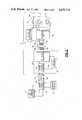
- FIGS. 2A and 2Btogether illustrate a circuit diagram in accordance with the present invention in which electrical power is transmitted concurrently along the same power conducting cable as downlink command communications and uplink data communications in a half duplex mode;
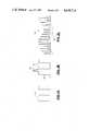
- FIGS. 3A, 3B, and 3Cillustrate electrical wave forms in conjunction with the power and communication signal transmissions.
- FIG. 1shows a first station A, which is commonly disposed on land, which provides appropriate electrical power and command signals to a transmission cable or conductor B.
- the cableextends from the first station to a second, controlled station C, which is commonly disposed in a remote, underwater location.
- the first station Aincludes a source 10 of electrical power, particularly DC electrical power.
- a command encoder 12selectively generates command signals which are superimposed by a signal combiner 14.
- the command encodergenerates low frequency AC command communication signals.
- the signal combiner 14may comprise a transformer or other components which combine the DC electrical power signal and the low frequency command communication signal.
- the various preselected commandsare distinguished by frequency modulating the command communication signal.
- preselected frequency shifts of the AC command communication signaldesignate ones and zeros of a digitally encoded transmission.
- a plurality of discrete frequencieseach designate a different one of the preselected commands.
- the command encoderprovides a digital command communication signal by superimposing square wave pulses on the DC electrical power signal. The binary ones and zeros may be designated by the presence and absence of such a pulse, by pulses of differing polarity, or the like.
- the cable Bincludes a pair of wires 20, 22 having good conductivity and with good insulation therearound. When transmitting DC electrical power, capacitance between the wires is of relatively small importance.
- the cableis connected with a coupler circuit 30 for converting the command signal encoded DC electrical power signal into a high frequency signal encoded in accordance with the command.
- a power and command signal separator 32reads the encoded command signal and produces an output signal in accordance therewith.
- the signal separator circuit 32preferably includes a voltage level detector which detects variations in voltage during each cycle of the AC command signal. The voltage level detector will also detect a digital command communication signal which includes a plurality of pulses or pulses of opposite polarity.
- the separator circuitmay include filter circuits for passing AC components but not DC components, transformers, and other circuits which produce an output which varies in proportion to the selected control communication signal.
- the output of the signal separator circuit 32is connected with a DC to AC converter 34 to control the frequency modulation of the converter in accordance with the control communication signal.
- a filter and rectifiermay advantageously be provided to assure that only DC power is received by the DC to AC converter.
- a signal processor 36may be interconnected between the signal separator 32 and the DC to AC converter 34.
- the signal processoris preferred when the command communication signal is digitally encoded.
- the signal processorreads the appropriate ones and zeros, ascertains the transmitted control signal, and causes the converter to modulate the high frequency signal correspondingly.
- the DC to AC converterproduces an output with a constant frequency and variable pulse width.
- the control signalmodulates the output high frequency signal by varying the pulse width in accordance with the control signal.
- the exact frequency of the high frequency signalis selected in accordance with the construction of an inductive coupler 40. Specifically, the high frequency is selected to coincide with the optimal transfer frequency of a primary ferromagnetic core 42, preferably a ferrite composition. Alternately, the control signal may vary the frequency of the high frequency signal about the optimal transfer frequency.
- the modulated high frequency signalis applied to a primary winding 42 which is magnetically coupled to a primary ferromagnetic core 44, preferably of a ferrite composition.
- the primary coreis magnetically coupled to a secondary ferromagnetic core 46.
- Secondary windings 48which are wrapped around the secondary magnetic core convert the transferred magnetic signals back into a modulated high frequency electrical signal.
- the inductivity coupled remote equipmentincludes a command unit 50 and a power supply 52 connected with the secondary coupler winding 48.
- the command unitreads the frequency encoded command signal and causes a preselected response.
- the control unitcauses one or more of switches 54 to be closed for supplying power to one or more components 56, or to be opened for terminating the supply of power thereto.
- signals from the first station Acontrol various remote components, such as test circuits for testing various physical conditions adjacent the equipment, motive power means for moving the equipment, lights, heaters, pumps, or the like.
- the exact command unit constructionvaries with the selected frequency modulation encoding scheme.
- the command unitrectifies the high frequency signal.
- the voltage of the rectified high frequency signalvaries in proportion to the width of the square wave.
- the appropriate switch(es)can be closed.
- the rectified high frequency signal magnitudecan be digitized and used to address a pre-programmed memory, such as a PROM chip.
- a series of descending frequency filtersmay compare the high frequency signal with preselected frequencies and address the memory.
- FIGS. 2A and 2Billustrates a combined electrical power, downlink control communication, and uplink data communication system in which like components of FIG. 1 are identified by like reference numerals with a primed (') suffix and new components are identified by new numerals.
- the first station Aincludes a DC power source 10', and command signal encoder 12', and a signal combiner 14' for combining the DC power and command communication signals.
- a wire pair 20', 22' of the cable Bconveys the encoded power signal to the remote station C.
- a power and command communication signal separator 32'separates the command communication signal from the power signal.
- a signal processor 36'converts the command signal into an appropriate modulation control for a DC to AC converter 34'.
- the DC to AC converterproduces a high frequency signal which is modulated in accordance with the command communication signal to convey the command contained therein to and across an inductive coupler 40'.
- the signal processormay modulate the frequency, pulse width, or other frequency related functions of the DC to AC converter 34'.
- the high frequency signalis electromagnetically conveyed to a first detachable portion of an inductive coupler 40'.
- a command decode unit 50' and a rectifier 52'are connected with a second magnetically coupled portion of the inductive coupler.
- the command decode unitmonitors the encoded frequency modulation and derives the corresponding commands therefrom to control switches 54' and components 56'.
- the rectifier 52'converts the high frequency signal to a DC power signal.
- the command decode unitmay be connected with the downstream end of the rectifier.
- a DC regulator 60converts the variable DC component from the rectifier 52' into a regulated DC power source, eg., 7.5 VDC.
- a condition monitorsuch as a full bridge pressure transducer 62.
- the condition monitoris powered by the regulated DC power signal to produce an output which varies in coordination with a monitored condition, such as pressure.
- An amplifier 64adjusts the amplitude of the output of the transducer to the appropriate level for a voltage to frequency converter 66.
- the voltage to frequency converterproduces an output signal whose frequency varies in proportion to changes in the monitored condition.
- the voltage to frequency convertercyclically connects a load 68 across the rectifier with a frequency or periodicity which again varies with the sensed condition. Because the magnitude of the load 68 is large relative to the remainder of the circuit, connecting the load across the rectifier causes a significant increase in the amount of current drawn, and which increase is detectable across the inductive coupler 40'.
- the output of the DC to AC converter 34'is a square wave 70 of fixed amplitude and frequency, and whose pulse width is modulated in proportion to the control signal.
- an inductive flyback voltage spike 72occurs.
- the amplitude or energy content of each flyback voltage spikeis dependent upon the load which is connected with the inductive coupler.
- the flyback voltage spikeshave a greater amplitude or energy content when a smaller load is applied and a smaller amplitude or energy content when a larger load is applied. That is, the magnitude of the flyback voltage spikes varies or is modulated with the periodic application of the load 68.
- flyback voltage spike train 74is produced.
- the amplitude and energy content of the flyback voltage spike train 74varies with an envelope 76 which analogously varies with the frequency of the applied load 68.
- a decoder circuit 80detects the variations in the electrical load applied by the variable load or load modulator means 68 and transfers the information around the DC to AC converter to the cable B.
- a load modulation detector 82separates the flyback voltage spikes 72 from the square wave 70 and converts the flyback spikes to the envelope or oscillating signal 76 which oscillates at the same frequency as the frequency at which the voltage to frequency converter 66 applies the load 68.
- a low pass filter 84 and a shaper 86convert the envelope into a square wave whose frequency is the same as the voltage to frequency converter 66.
- a signal combining means 90superimposes the data communication information from the shaper 86 onto the cable B.
- the downlink control communication signals and the uplink data communication signalsmay be duplexed or alternated.
- the signal processor 36'under appropriate controls from the command encoder 12', may alternately enable the signal combiner 90 and disable the signal separator 32', and disable the signal combiner 90 and enable the signal separater 32'.
- the encoding techniques for applying the downlink control communication signals and the uplink data communication signalsmay be such that both may be conducted simultaneously along the cable B without interference.
- the downlink communicationsmay be encdoded with a frequency modulated low frequency voltage signal and the uplink communications may take the form of a current modulation.
- a resistive loadmay be connected between the hot wire of the cable B and ground by a switch controlled with the shaper 86 such that the load is applied with the same periodicity as load 68 which, in turn, is applied in proportion to the monitored condition.
- the uplink and downlink communicationsmay both be frequency modulations in significantly different frequency ranges such that the superimposed signals may be readily filtered or separated.
- the downlink communicationsmay be digitally encoded with square wave pulses of a first polarity and the uplink communications may be digitally encoded with square wave pulses of the opposite polarity. With appropriate filters in the signal separator 32', the uplink communications could be separated and discarded such that they do not affect the modulation of the DC to AC converter 34'.
- the first station Afurther includes an uplink communication signal separator 92 which separates the uplink data communication signal from the DC power signal and downlink command signals on the cable B.
- An appropriate decoder 94 for the selected uplink encoding techniqueconverts the uplink communication to an appropriate format for display.
- the decoder 94may convert the uplink data communication to a voltage which varies in proportion to the frequency of the voltage to frequency converter 66, hence, with changes in the sensed condition.
- the analog voltageis applied to a meter or other man-readable display 96 which provides an indication of the sensed condition.
Landscapes
- Engineering & Computer Science (AREA)
- Power Engineering (AREA)
- Computer Networks & Wireless Communication (AREA)
- Signal Processing (AREA)
- Dc Digital Transmission (AREA)
- Cable Transmission Systems, Equalization Of Radio And Reduction Of Echo (AREA)
Abstract
Description
Claims (20)
Priority Applications (1)
| Application Number | Priority Date | Filing Date | Title |
|---|---|---|---|
| US06/685,262US4639714A (en) | 1984-12-21 | 1984-12-21 | Combined power and control signal transmission system |
Applications Claiming Priority (1)
| Application Number | Priority Date | Filing Date | Title |
|---|---|---|---|
| US06/685,262US4639714A (en) | 1984-12-21 | 1984-12-21 | Combined power and control signal transmission system |
Publications (1)
| Publication Number | Publication Date |
|---|---|
| US4639714Atrue US4639714A (en) | 1987-01-27 |
Family
ID=24751429
Family Applications (1)
| Application Number | Title | Priority Date | Filing Date |
|---|---|---|---|
| US06/685,262Expired - Fee RelatedUS4639714A (en) | 1984-12-21 | 1984-12-21 | Combined power and control signal transmission system |
Country Status (1)
| Country | Link |
|---|---|
| US (1) | US4639714A (en) |
Cited By (50)
| Publication number | Priority date | Publication date | Assignee | Title |
|---|---|---|---|---|
| US4757213A (en)* | 1986-05-15 | 1988-07-12 | Werner Turch GmbH & Co. KG | Non-contact operating proximity switch |
| US4779071A (en)* | 1985-12-20 | 1988-10-18 | Pianelli and Traveisa S.A.S. | System for transmitting commands |
| US4788448A (en)* | 1984-12-06 | 1988-11-29 | Ferranti Subsea Systems, Ltd. | Power transfer of direct current with inductive couplings |
| US4941079A (en)* | 1988-10-07 | 1990-07-10 | The Royal Institution For The Advancement Of Learning | Pulse width modulation power transmission system |
| US5051720A (en)* | 1989-11-13 | 1991-09-24 | Secure Telecom, Inc. | Remote control system using power line of remote site |
| US5477091A (en)* | 1991-11-27 | 1995-12-19 | Merlin Gerin | High quality electrical power distribution system |
| US5539388A (en)* | 1993-02-11 | 1996-07-23 | National Digital Electronics, Inc. | Telemetry and control system |
| US5572182A (en)* | 1993-02-17 | 1996-11-05 | Petrolew Brasileiro S.A. - Petrobras | Integrated power and signal transmission system |
| US5644286A (en)* | 1993-10-04 | 1997-07-01 | Lockheed Martin Corporation | Power bus digital communication system |
| US5866956A (en)* | 1995-06-06 | 1999-02-02 | Dekko Engineering, Inc. | Apparatus for and method of monitoring and controlling a power system |
| US5890779A (en)* | 1997-04-08 | 1999-04-06 | Trw Vehicle Safety Systems Inc. | Apparatus for providing electrical communication between parts of a vehicle |
| US6449348B1 (en)* | 1997-05-29 | 2002-09-10 | 3Com Corporation | Power transfer apparatus for use by network devices including telephone equipment |
| US20020159402A1 (en)* | 1998-07-28 | 2002-10-31 | Yehuda Binder | Local area network of serial intelligent cells |
| US6545591B2 (en)* | 1999-02-10 | 2003-04-08 | Symon Communications, Inc. | Apparatus for providing power to a visual messaging system for high-speed networks |
| US6580254B2 (en)* | 2001-03-09 | 2003-06-17 | Adtran, Inc. | Apparatus and method for providing span power to communication equipment at a customer premise |
| US20040062203A1 (en)* | 1998-04-10 | 2004-04-01 | Austermann John F. | System for communicating with electronic equipment |
| US20040239448A1 (en)* | 2003-05-30 | 2004-12-02 | Lomax Charles Weston | Splitter |
| US20040239512A1 (en)* | 2003-05-30 | 2004-12-02 | Adc Dsl Systems, Inc. | Lightning protection for a network element |
| US20040246753A1 (en)* | 2001-09-19 | 2004-12-09 | Peter Kunow | DC converter |
| US20040252431A1 (en)* | 2001-09-19 | 2004-12-16 | Peter Kunow | Universal energy supply system |
| US20040262998A1 (en)* | 2001-09-19 | 2004-12-30 | Peter Kunow | Dc voltage converting device |
| US20050013148A1 (en)* | 2001-09-19 | 2005-01-20 | Peter Kunow | Universal power supply system |
| US20050025162A1 (en)* | 2002-11-13 | 2005-02-03 | Yehuda Binder | Addressable outlet, and a network using same |
| US20050029476A1 (en)* | 2000-05-11 | 2005-02-10 | Cooper Cameron Corporation | Electric control and supply system |
| US20050105477A1 (en)* | 1999-07-20 | 2005-05-19 | Serconet, Ltd. | Network for telephony and data communication |
| US20050135120A1 (en)* | 2003-12-21 | 2005-06-23 | Nikholas Hubbard | Transmitting signals over interconnect carrying direct current from power supply to electronic device |
| US20050185349A1 (en)* | 2000-10-30 | 2005-08-25 | Klaus Biester | Control and supply system |
| US20050254494A1 (en)* | 2000-09-21 | 2005-11-17 | Serconet, Ltd. | Telephone communication system and method over local area network wiring |
| US20060133588A1 (en)* | 2000-03-20 | 2006-06-22 | Serconet Ltd. | Telephone outlet for implementing a local area network over telephone lines and a local area network using such outlets |
| US7091853B2 (en)* | 2003-12-11 | 2006-08-15 | Lucent Technologies Inc. | X10 communication of one or more messages between one or more mobile communication devices and one or more module components |
| US20060209847A1 (en)* | 1999-07-07 | 2006-09-21 | Serconet, Ltd. | Local area network for distributing data communication, sensing and control signals |
| US20070046222A1 (en)* | 2005-08-31 | 2007-03-01 | Caterpillar Inc. | System and method for electric motor control |
| US20070070911A1 (en)* | 2005-09-29 | 2007-03-29 | Goldberg Keith J | Method for testing links in a wireless network |
| US20070069678A1 (en)* | 2005-09-28 | 2007-03-29 | Caterpillar Inc. | Integrated motor monitoring system |
| US20070217101A1 (en)* | 2006-03-17 | 2007-09-20 | Adc Dsl Systems, Inc. | Auto-resetting span-power protection |
| US20090117873A1 (en)* | 2007-10-01 | 2009-05-07 | Edson Leocadio Ferreira | Electric device |
| US20090132679A1 (en)* | 2004-01-13 | 2009-05-21 | Serconet, Ltd. | Information device |
| US20090257580A1 (en)* | 2002-04-29 | 2009-10-15 | Adc Dsl Systems, Inc. | Function for controlling line powered network element |
| US7620171B2 (en) | 2004-10-29 | 2009-11-17 | Hubbell Incorporated | Method and apparatus for powering a DS3 device |
| US20100057970A1 (en)* | 2008-08-29 | 2010-03-04 | Mostafa Kashi | Method and apparatus to combine power and control signals in a mobile computing device |
| US20100103702A1 (en)* | 1999-06-21 | 2010-04-29 | Access Business Group International Llc | Adaptive inductive power supply |
| US20100244561A1 (en)* | 2001-09-19 | 2010-09-30 | Cameron International Corporation | DC Voltage Converting Device |
| US20110177783A1 (en)* | 2003-02-04 | 2011-07-21 | Access Business Group International Llc | Adaptive inductive power supply with communication |
| US20130043034A1 (en)* | 2011-08-16 | 2013-02-21 | Didier Drablier | Power and control pod for a subsea artificial lift system |
| US20130154366A1 (en)* | 2010-02-19 | 2013-06-20 | The University Of Strathclyde | Powering of devices |
| US20140084701A1 (en)* | 2012-09-26 | 2014-03-27 | Lg Innotek Co., Ltd. | Wireless power transmitter and method of controlling power thereof |
| US20140292297A1 (en)* | 2013-04-02 | 2014-10-02 | Bel Fuse (Macao Commercial Offshore) Limited | Power supply having selectable operation based on communications with load |
| US8873586B2 (en) | 2000-04-19 | 2014-10-28 | Conversant Intellectual Property Management Incorporated | Network combining wired and non-wired segments |
| US9257851B2 (en) | 2008-01-07 | 2016-02-09 | Access Business Group International Llc | Inductive power supply with duty cycle control |
| US11015829B2 (en)* | 2016-04-29 | 2021-05-25 | Regal Beloit America, Inc. | System, motor controller and associated method |
Citations (11)
| Publication number | Priority date | Publication date | Assignee | Title |
|---|---|---|---|---|
| US3061734A (en)* | 1959-09-11 | 1962-10-30 | Dresser Ind | Well logging caliper motor control system |
| US3374459A (en)* | 1965-04-16 | 1968-03-19 | Pgac Dev Company | Logging channel disabling circuit |
| US3717858A (en)* | 1970-08-12 | 1973-02-20 | D Hadden | Two conductor telemetering system |
| US3742473A (en)* | 1970-08-12 | 1973-06-26 | D Hadden | Pulse discriminator and telemetering systems using same |
| US3786423A (en)* | 1972-01-24 | 1974-01-15 | Northern Illinois Gas Co | Apparatus for cumulatively storing and remotely reading a meter |
| US3795817A (en)* | 1972-03-03 | 1974-03-05 | Thomson Csf | Power transmission device in particular for a submarine camera |
| US4118977A (en)* | 1976-10-13 | 1978-10-10 | The Foxboro Company | Electric signal transmitter for vibrating-wire sensor |
| US4130861A (en)* | 1976-12-22 | 1978-12-19 | General Electric Company | Power line carrier noise elimination |
| US4173754A (en)* | 1977-03-17 | 1979-11-06 | General Electric Company | Distributed control system |
| US4296450A (en)* | 1979-10-05 | 1981-10-20 | The United States Of America As Represented By The Secretary Of The Interior | Discriminating circuit breaker protection system direct current power distribution systems |
| US4442515A (en)* | 1981-12-17 | 1984-04-10 | Ford Motor Company | Multiplex transmission medium for application in multiplex vehicle control systems |
- 1984
- 1984-12-21USUS06/685,262patent/US4639714A/ennot_activeExpired - Fee Related
Patent Citations (11)
| Publication number | Priority date | Publication date | Assignee | Title |
|---|---|---|---|---|
| US3061734A (en)* | 1959-09-11 | 1962-10-30 | Dresser Ind | Well logging caliper motor control system |
| US3374459A (en)* | 1965-04-16 | 1968-03-19 | Pgac Dev Company | Logging channel disabling circuit |
| US3717858A (en)* | 1970-08-12 | 1973-02-20 | D Hadden | Two conductor telemetering system |
| US3742473A (en)* | 1970-08-12 | 1973-06-26 | D Hadden | Pulse discriminator and telemetering systems using same |
| US3786423A (en)* | 1972-01-24 | 1974-01-15 | Northern Illinois Gas Co | Apparatus for cumulatively storing and remotely reading a meter |
| US3795817A (en)* | 1972-03-03 | 1974-03-05 | Thomson Csf | Power transmission device in particular for a submarine camera |
| US4118977A (en)* | 1976-10-13 | 1978-10-10 | The Foxboro Company | Electric signal transmitter for vibrating-wire sensor |
| US4130861A (en)* | 1976-12-22 | 1978-12-19 | General Electric Company | Power line carrier noise elimination |
| US4173754A (en)* | 1977-03-17 | 1979-11-06 | General Electric Company | Distributed control system |
| US4296450A (en)* | 1979-10-05 | 1981-10-20 | The United States Of America As Represented By The Secretary Of The Interior | Discriminating circuit breaker protection system direct current power distribution systems |
| US4442515A (en)* | 1981-12-17 | 1984-04-10 | Ford Motor Company | Multiplex transmission medium for application in multiplex vehicle control systems |
Cited By (177)
| Publication number | Priority date | Publication date | Assignee | Title |
|---|---|---|---|---|
| US4788448A (en)* | 1984-12-06 | 1988-11-29 | Ferranti Subsea Systems, Ltd. | Power transfer of direct current with inductive couplings |
| US4779071A (en)* | 1985-12-20 | 1988-10-18 | Pianelli and Traveisa S.A.S. | System for transmitting commands |
| US4757213A (en)* | 1986-05-15 | 1988-07-12 | Werner Turch GmbH & Co. KG | Non-contact operating proximity switch |
| US4941079A (en)* | 1988-10-07 | 1990-07-10 | The Royal Institution For The Advancement Of Learning | Pulse width modulation power transmission system |
| US5051720A (en)* | 1989-11-13 | 1991-09-24 | Secure Telecom, Inc. | Remote control system using power line of remote site |
| US5477091A (en)* | 1991-11-27 | 1995-12-19 | Merlin Gerin | High quality electrical power distribution system |
| US5539388A (en)* | 1993-02-11 | 1996-07-23 | National Digital Electronics, Inc. | Telemetry and control system |
| US5572182A (en)* | 1993-02-17 | 1996-11-05 | Petrolew Brasileiro S.A. - Petrobras | Integrated power and signal transmission system |
| US5644286A (en)* | 1993-10-04 | 1997-07-01 | Lockheed Martin Corporation | Power bus digital communication system |
| US5866956A (en)* | 1995-06-06 | 1999-02-02 | Dekko Engineering, Inc. | Apparatus for and method of monitoring and controlling a power system |
| US5890779A (en)* | 1997-04-08 | 1999-04-06 | Trw Vehicle Safety Systems Inc. | Apparatus for providing electrical communication between parts of a vehicle |
| JP2955554B2 (en) | 1997-04-08 | 1999-10-04 | ティーアールダブリュー・ヴィークル・セーフティ・システムズ・インコーポレーテッド | Apparatus for conducting electrical transmission between vehicle components |
| US6449348B1 (en)* | 1997-05-29 | 2002-09-10 | 3Com Corporation | Power transfer apparatus for use by network devices including telephone equipment |
| US6658098B2 (en)* | 1997-05-29 | 2003-12-02 | 3Com Corporation | Power transfer apparatus for use by network devices including telephone equipment |
| US8155012B2 (en) | 1998-04-10 | 2012-04-10 | Chrimar Systems, Inc. | System and method for adapting a piece of terminal equipment |
| US9049019B2 (en) | 1998-04-10 | 2015-06-02 | Chrimar Systems, Inc. | Network equipment and optional tether |
| US20090022057A1 (en)* | 1998-04-10 | 2009-01-22 | Austermann John F Iii | System and method for communicating with objects on a network |
| US20040062203A1 (en)* | 1998-04-10 | 2004-04-01 | Austermann John F. | System for communicating with electronic equipment |
| US8902760B2 (en) | 1998-04-10 | 2014-12-02 | Chrimar Systems, Inc. | Network system and optional tethers |
| US8942107B2 (en) | 1998-04-10 | 2015-01-27 | Chrimar Systems, Inc. | Piece of ethernet terminal equipment |
| US9812825B2 (en) | 1998-04-10 | 2017-11-07 | Chrimar Systems, Inc. | Ethernet device |
| US9019838B2 (en) | 1998-04-10 | 2015-04-28 | Chrimar Systems, Inc. | Central piece of network equipment |
| US7653015B2 (en) | 1998-07-28 | 2010-01-26 | Mosaid Technologies Incorporated | Local area network of serial intelligent cells |
| US20060251110A1 (en)* | 1998-07-28 | 2006-11-09 | Isreali Company Of Serconet Ltd. | Local area network of serial intelligent cells |
| US20020159402A1 (en)* | 1998-07-28 | 2002-10-31 | Yehuda Binder | Local area network of serial intelligent cells |
| US20050013320A1 (en)* | 1998-07-28 | 2005-01-20 | Serconet Ltd. | Local area network of serial intelligent cells |
| US20100154022A1 (en)* | 1998-07-28 | 2010-06-17 | Mosaid Technologies Incorporated | Local area network of serial intelligent cells |
| US8270430B2 (en) | 1998-07-28 | 2012-09-18 | Mosaid Technologies Incorporated | Local area network of serial intelligent cells |
| US8325636B2 (en) | 1998-07-28 | 2012-12-04 | Mosaid Technologies Incorporated | Local area network of serial intelligent cells |
| US7830858B2 (en) | 1998-07-28 | 2010-11-09 | Mosaid Technologies Incorporated | Local area network of serial intelligent cells |
| US7852874B2 (en) | 1998-07-28 | 2010-12-14 | Mosaid Technologies Incorporated | Local area network of serial intelligent cells |
| US8867523B2 (en) | 1998-07-28 | 2014-10-21 | Conversant Intellectual Property Management Incorporated | Local area network of serial intelligent cells |
| US20050163152A1 (en)* | 1998-07-28 | 2005-07-28 | Serconet Ltd. | Local area network of serial intelligent cells |
| US7965735B2 (en) | 1998-07-28 | 2011-06-21 | Mosaid Technologies Incorporated | Local area network of serial intelligent cells |
| US20080219288A1 (en)* | 1998-07-28 | 2008-09-11 | Israeli Company Of Serconet Ltd. | Local area network of serial intelligent cells |
| US7986708B2 (en) | 1998-07-28 | 2011-07-26 | Mosaid Technologies Incorporated | Local area network of serial intelligent cells |
| US20060018339A1 (en)* | 1998-07-28 | 2006-01-26 | Serconet, Ltd | Local area network of serial intelligent cells |
| US20060018338A1 (en)* | 1998-07-28 | 2006-01-26 | Serconet, Ltd. | Local area network of serial intelligent cells |
| US7424031B2 (en) | 1998-07-28 | 2008-09-09 | Serconet, Ltd. | Local area network of serial intelligent cells |
| US7006523B2 (en) | 1998-07-28 | 2006-02-28 | Serconet Ltd. | Local area network of serial intelligent cells |
| US20060056444A1 (en)* | 1998-07-28 | 2006-03-16 | Serconet, Ltd | Local area network of serial intelligent cells |
| US7016368B2 (en) | 1998-07-28 | 2006-03-21 | Serconet, Ltd. | Local area network of serial intelligent cells |
| US20060062241A1 (en)* | 1998-07-28 | 2006-03-23 | Serconet, Ltd | Local area network of serial intelligent cells |
| US20060077970A1 (en)* | 1998-07-28 | 2006-04-13 | Serconet, Ltd | Local area network of serial intelligent cells |
| US7035280B2 (en) | 1998-07-28 | 2006-04-25 | Serconet Ltd. | Local area network of serial intelligent cells |
| US20060092962A1 (en)* | 1998-07-28 | 2006-05-04 | Serconet, Ltd | Local area network of serial intelligent cells |
| US7969917B2 (en) | 1998-07-28 | 2011-06-28 | Mosaid Technologies Incorporated | Local area network of serial intelligent cells |
| US8885659B2 (en) | 1998-07-28 | 2014-11-11 | Conversant Intellectual Property Management Incorporated | Local area network of serial intelligent cells |
| US7095756B2 (en) | 1998-07-28 | 2006-08-22 | Serconet, Ltd. | Local area network of serial intelligent cells |
| US7292600B2 (en) | 1998-07-28 | 2007-11-06 | Serconet Ltd. | Local area network of serial intellegent cells |
| US7978726B2 (en) | 1998-07-28 | 2011-07-12 | Mosaid Technologies Incorporated | Local area network of serial intelligent cells |
| US8885660B2 (en) | 1998-07-28 | 2014-11-11 | Conversant Intellectual Property Management Incorporated | Local area network of serial intelligent cells |
| US20060291497A1 (en)* | 1998-07-28 | 2006-12-28 | Israeli Company Of Serconet Ltd. | Local area network of serial intelligent cells |
| US20040174897A1 (en)* | 1998-07-28 | 2004-09-09 | Israeli Company Of Serconet Ltd. | Local area network of serial intellegent cells |
| US7187695B2 (en) | 1998-07-28 | 2007-03-06 | Serconet Ltd. | Local area network of serial intelligent cells |
| US20040170189A1 (en)* | 1998-07-28 | 2004-09-02 | Israeli Company Of Serconet Ltd. | Local area network of serial intellegent cells |
| US8908673B2 (en) | 1998-07-28 | 2014-12-09 | Conversant Intellectual Property Management Incorporated | Local area network of serial intelligent cells |
| US7221679B2 (en) | 1998-07-28 | 2007-05-22 | Serconet Ltd. | Local area network of serial intelligent cells |
| US20070147413A1 (en)* | 1998-07-28 | 2007-06-28 | Israeli Company Of Serconet Ltd. | Local area network of serial intelligent cells |
| US6545591B2 (en)* | 1999-02-10 | 2003-04-08 | Symon Communications, Inc. | Apparatus for providing power to a visual messaging system for high-speed networks |
| US20100103702A1 (en)* | 1999-06-21 | 2010-04-29 | Access Business Group International Llc | Adaptive inductive power supply |
| US8351856B2 (en) | 1999-06-21 | 2013-01-08 | Access Business Group International Llc | Adaptive inductive power supply with communication |
| US8855558B2 (en) | 1999-06-21 | 2014-10-07 | Access Business Group International Llc | Adaptive inductive power supply with communication |
| US9368976B2 (en) | 1999-06-21 | 2016-06-14 | Access Business Group International Llc | Adaptive inductive power supply with communication |
| US8346167B2 (en) | 1999-06-21 | 2013-01-01 | Access Business Group International Llc | Adaptive inductive power supply with communication |
| US9036371B2 (en) | 1999-06-21 | 2015-05-19 | Access Business Group International Llc | Adaptive inductive power supply |
| US7835386B2 (en) | 1999-07-07 | 2010-11-16 | Mosaid Technologies Incorporated | Local area network for distributing data communication, sensing and control signals |
| US8582598B2 (en) | 1999-07-07 | 2013-11-12 | Mosaid Technologies Incorporated | Local area network for distributing data communication, sensing and control signals |
| US20060209847A1 (en)* | 1999-07-07 | 2006-09-21 | Serconet, Ltd. | Local area network for distributing data communication, sensing and control signals |
| US8121132B2 (en) | 1999-07-07 | 2012-02-21 | Mosaid Technologies Incorporated | Local area network for distributing data communication, sensing and control signals |
| US20080292073A1 (en)* | 1999-07-20 | 2008-11-27 | Serconet, Ltd | Network for telephony and data communication |
| US20050105477A1 (en)* | 1999-07-20 | 2005-05-19 | Serconet, Ltd. | Network for telephony and data communication |
| US20050111636A1 (en)* | 1999-07-20 | 2005-05-26 | Serconet, Ltd | Network for telephony and data communication |
| US7483524B2 (en) | 1999-07-20 | 2009-01-27 | Serconet, Ltd | Network for telephony and data communication |
| US8929523B2 (en) | 1999-07-20 | 2015-01-06 | Conversant Intellectual Property Management Inc. | Network for telephony and data communication |
| US7492875B2 (en) | 1999-07-20 | 2009-02-17 | Serconet, Ltd. | Network for telephony and data communication |
| US20050226226A1 (en)* | 1999-07-20 | 2005-10-13 | Serconet, Ltd. | Network for telephony and data communication |
| US8351582B2 (en) | 1999-07-20 | 2013-01-08 | Mosaid Technologies Incorporated | Network for telephony and data communication |
| US7522713B2 (en) | 1999-07-20 | 2009-04-21 | Serconet, Ltd. | Network for telephony and data communication |
| US20060133588A1 (en)* | 2000-03-20 | 2006-06-22 | Serconet Ltd. | Telephone outlet for implementing a local area network over telephone lines and a local area network using such outlets |
| US8855277B2 (en) | 2000-03-20 | 2014-10-07 | Conversant Intellectual Property Managment Incorporated | Telephone outlet for implementing a local area network over telephone lines and a local area network using such outlets |
| US7123701B2 (en) | 2000-03-20 | 2006-10-17 | Serconet, Ltd. | Telephone outlet for implementing a local area network over telephone lines and a local area network using such outlets |
| US8363797B2 (en) | 2000-03-20 | 2013-01-29 | Mosaid Technologies Incorporated | Telephone outlet for implementing a local area network over telephone lines and a local area network using such outlets |
| US7522714B2 (en) | 2000-03-20 | 2009-04-21 | Serconet Ltd. | Telephone outlet for implementing a local area network over telephone lines and a local area network using such outlets |
| US8982904B2 (en) | 2000-04-19 | 2015-03-17 | Conversant Intellectual Property Management Inc. | Network combining wired and non-wired segments |
| US8873586B2 (en) | 2000-04-19 | 2014-10-28 | Conversant Intellectual Property Management Incorporated | Network combining wired and non-wired segments |
| US7615893B2 (en) | 2000-05-11 | 2009-11-10 | Cameron International Corporation | Electric control and supply system |
| US20050029476A1 (en)* | 2000-05-11 | 2005-02-10 | Cooper Cameron Corporation | Electric control and supply system |
| US20050254494A1 (en)* | 2000-09-21 | 2005-11-17 | Serconet, Ltd. | Telephone communication system and method over local area network wiring |
| US8619538B2 (en) | 2000-09-21 | 2013-12-31 | Mosaid Technologies Incorporated | Communication system and method over local area network wiring |
| US7447144B2 (en) | 2000-09-21 | 2008-11-04 | Serconet, Ltd. | Telephone communication system and method over local area network wiring |
| US7489709B2 (en) | 2000-09-21 | 2009-02-10 | Serconet Ltd. | Telephone communication system and method over local area network wiring |
| US7843799B2 (en) | 2000-09-21 | 2010-11-30 | Mosaid Technologies Incorporated | Telephone communication system and method over local area network wiring |
| US20110038368A1 (en)* | 2000-09-21 | 2011-02-17 | Mosaid Technologies Incorporated | Telephone communication system and method over local area network wiring |
| US7480233B2 (en) | 2000-09-21 | 2009-01-20 | Serconet Ltd. | Telephone communication system and method over local area network wiring |
| US8817779B2 (en) | 2000-09-21 | 2014-08-26 | Conversant Intellectual Property Management Incorporated | Telephone communication system and method over local area network wiring |
| US7576447B2 (en)* | 2000-10-30 | 2009-08-18 | Cameron International Corporation | Control and supply system |
| US20090296428A1 (en)* | 2000-10-30 | 2009-12-03 | Cameron International Corporation | Control and supply system |
| US20050185349A1 (en)* | 2000-10-30 | 2005-08-25 | Klaus Biester | Control and supply system |
| US8212378B2 (en) | 2000-10-30 | 2012-07-03 | Cameron International Corporation | Control and supply system |
| US6580254B2 (en)* | 2001-03-09 | 2003-06-17 | Adtran, Inc. | Apparatus and method for providing span power to communication equipment at a customer premise |
| US8536731B2 (en) | 2001-05-07 | 2013-09-17 | Cameron International Corporation | Electric control and supply system |
| US20100019573A1 (en)* | 2001-05-07 | 2010-01-28 | Cameron International Corporation | Electric control and supply system |
| US20040252431A1 (en)* | 2001-09-19 | 2004-12-16 | Peter Kunow | Universal energy supply system |
| US7433214B2 (en) | 2001-09-19 | 2008-10-07 | Cameron International Corporation | DC converter |
| US7453170B2 (en) | 2001-09-19 | 2008-11-18 | Cameron International Corporation | Universal energy supply system |
| US20100244561A1 (en)* | 2001-09-19 | 2010-09-30 | Cameron International Corporation | DC Voltage Converting Device |
| US8492927B2 (en) | 2001-09-19 | 2013-07-23 | Cameron International Corporation | Universal power supply system |
| US20040262998A1 (en)* | 2001-09-19 | 2004-12-30 | Peter Kunow | Dc voltage converting device |
| US7759827B2 (en) | 2001-09-19 | 2010-07-20 | Cameron International Corporation | DC voltage converting device having a plurality of DC voltage converting units connected in series on an input side and in parallel on an output side |
| US7851949B2 (en) | 2001-09-19 | 2010-12-14 | Cameron International Corporation | DC converter |
| US7683505B2 (en) | 2001-09-19 | 2010-03-23 | Cameron International Corporation | Universal energy supply system |
| US20040246753A1 (en)* | 2001-09-19 | 2004-12-09 | Peter Kunow | DC converter |
| US20050013148A1 (en)* | 2001-09-19 | 2005-01-20 | Peter Kunow | Universal power supply system |
| US8106538B2 (en) | 2001-09-19 | 2012-01-31 | Cameron International Corporation | DC voltage converting device |
| US8106536B2 (en) | 2001-09-19 | 2012-01-31 | Cameron International Corporation | Universal power supply system |
| US8073134B2 (en) | 2002-04-29 | 2011-12-06 | Adc Dsl Systems, Inc. | Function for controlling line powered network element |
| US20090257580A1 (en)* | 2002-04-29 | 2009-10-15 | Adc Dsl Systems, Inc. | Function for controlling line powered network element |
| US20100019930A1 (en)* | 2002-11-12 | 2010-01-28 | Camerson International Corporation | Electric Control and Supply System |
| US8212410B2 (en) | 2002-11-12 | 2012-07-03 | Cameron International Corporation | Electric control and supply system |
| US7990908B2 (en) | 2002-11-13 | 2011-08-02 | Mosaid Technologies Incorporated | Addressable outlet, and a network using the same |
| US8295185B2 (en) | 2002-11-13 | 2012-10-23 | Mosaid Technologies Inc. | Addressable outlet for use in wired local area network |
| US20080198777A1 (en)* | 2002-11-13 | 2008-08-21 | Serconet Ltd. | Addressable outlet, and a network using the same |
| US20050025162A1 (en)* | 2002-11-13 | 2005-02-03 | Yehuda Binder | Addressable outlet, and a network using same |
| US7522615B2 (en) | 2002-11-13 | 2009-04-21 | Serconet, Ltd. | Addressable outlet, and a network using same |
| US7911992B2 (en) | 2002-11-13 | 2011-03-22 | Mosaid Technologies Incorporated | Addressable outlet, and a network using the same |
| US9246356B2 (en) | 2003-02-04 | 2016-01-26 | Access Business Group International Llc | Adaptive inductive power supply |
| US8315561B2 (en) | 2003-02-04 | 2012-11-20 | Access Business Group International Llc | Adaptive inductive power supply with communication |
| US20110175458A1 (en)* | 2003-02-04 | 2011-07-21 | Access Business Group International Llc | Adaptive inductive power supply |
| US20110177783A1 (en)* | 2003-02-04 | 2011-07-21 | Access Business Group International Llc | Adaptive inductive power supply with communication |
| US20110189954A1 (en)* | 2003-02-04 | 2011-08-04 | Access Business Group International Llc | Adaptive inductive power supply with communication |
| US9013895B2 (en) | 2003-02-04 | 2015-04-21 | Access Business Group International Llc | Adaptive inductive power supply |
| US8301079B2 (en) | 2003-02-04 | 2012-10-30 | Access Business Group International Llc | Adaptive inductive power supply with communication |
| US10505385B2 (en) | 2003-02-04 | 2019-12-10 | Philips Ip Ventures B.V. | Adaptive inductive power supply |
| US10439437B2 (en) | 2003-02-04 | 2019-10-08 | Philips Ip Ventures B.V. | Adaptive inductive power supply with communication |
| US8301080B2 (en) | 2003-02-04 | 2012-10-30 | Access Business Group International Llc | Adaptive inductive power supply with communication |
| US8538330B2 (en) | 2003-02-04 | 2013-09-17 | Access Business Group International Llc | Adaptive inductive power supply with communication |
| US9906049B2 (en) | 2003-02-04 | 2018-02-27 | Access Business Group International Llc | Adaptive inductive power supply |
| US8346166B2 (en) | 2003-02-04 | 2013-01-01 | Access Business Group International Llc | Adaptive inductive power supply with communication |
| US9190874B2 (en) | 2003-02-04 | 2015-11-17 | Access Business Group International Llc | Adaptive inductive power supply |
| US8831513B2 (en) | 2003-02-04 | 2014-09-09 | Access Business Group International Llc | Adaptive inductive power supply with communication |
| US20040239512A1 (en)* | 2003-05-30 | 2004-12-02 | Adc Dsl Systems, Inc. | Lightning protection for a network element |
| US6998964B2 (en) | 2003-05-30 | 2006-02-14 | Adc Dsl Systems, Inc. | Splitter |
| US20040239448A1 (en)* | 2003-05-30 | 2004-12-02 | Lomax Charles Weston | Splitter |
| US7091853B2 (en)* | 2003-12-11 | 2006-08-15 | Lucent Technologies Inc. | X10 communication of one or more messages between one or more mobile communication devices and one or more module components |
| US20050135120A1 (en)* | 2003-12-21 | 2005-06-23 | Nikholas Hubbard | Transmitting signals over interconnect carrying direct current from power supply to electronic device |
| US7800253B2 (en) | 2003-12-21 | 2010-09-21 | Hewlett-Packard Development Company, L.P. | Transmitting signals over interconnect carrying direct current from power supply to electronic device |
| US10986164B2 (en) | 2004-01-13 | 2021-04-20 | May Patents Ltd. | Information device |
| US11095708B2 (en) | 2004-01-13 | 2021-08-17 | May Patents Ltd. | Information device |
| US20090132679A1 (en)* | 2004-01-13 | 2009-05-21 | Serconet, Ltd. | Information device |
| US11032353B2 (en) | 2004-01-13 | 2021-06-08 | May Patents Ltd. | Information device |
| US7620171B2 (en) | 2004-10-29 | 2009-11-17 | Hubbell Incorporated | Method and apparatus for powering a DS3 device |
| US7282875B2 (en) | 2005-08-31 | 2007-10-16 | Caterpillar Inc. | System and method for electric motor control |
| US20070046222A1 (en)* | 2005-08-31 | 2007-03-01 | Caterpillar Inc. | System and method for electric motor control |
| US7298110B2 (en) | 2005-09-28 | 2007-11-20 | Caterpillar Inc. | Integrated motor monitoring system |
| US20070069678A1 (en)* | 2005-09-28 | 2007-03-29 | Caterpillar Inc. | Integrated motor monitoring system |
| US20070070911A1 (en)* | 2005-09-29 | 2007-03-29 | Goldberg Keith J | Method for testing links in a wireless network |
| US20070217101A1 (en)* | 2006-03-17 | 2007-09-20 | Adc Dsl Systems, Inc. | Auto-resetting span-power protection |
| US7433165B2 (en) | 2006-03-17 | 2008-10-07 | Adc Dsl Systems, Inc. | Auto-resetting span-power protection |
| US8380142B2 (en)* | 2007-10-01 | 2013-02-19 | Siemens Aktiengesellschaft | Electronic device including a dual-function DC-to-DC converter |
| US20090117873A1 (en)* | 2007-10-01 | 2009-05-07 | Edson Leocadio Ferreira | Electric device |
| US9257851B2 (en) | 2008-01-07 | 2016-02-09 | Access Business Group International Llc | Inductive power supply with duty cycle control |
| US10170935B2 (en) | 2008-01-07 | 2019-01-01 | Philips Ip Ventures B.V. | Inductive power supply with duty cycle control |
| WO2010025205A3 (en)* | 2008-08-29 | 2010-07-01 | Palm, Inc. | Method and apparatus to combine power and control signals in a mobile computing device |
| US8051309B2 (en) | 2008-08-29 | 2011-11-01 | Hewlett-Packard Development Company, L.P. | Method and apparatus to combine power and control signals in a mobile computing device |
| US20100057970A1 (en)* | 2008-08-29 | 2010-03-04 | Mostafa Kashi | Method and apparatus to combine power and control signals in a mobile computing device |
| US20130154366A1 (en)* | 2010-02-19 | 2013-06-20 | The University Of Strathclyde | Powering of devices |
| US20130154367A1 (en)* | 2010-02-19 | 2013-06-20 | The University Of Strathclyde | Powering of devices |
| US20130043034A1 (en)* | 2011-08-16 | 2013-02-21 | Didier Drablier | Power and control pod for a subsea artificial lift system |
| US9151131B2 (en)* | 2011-08-16 | 2015-10-06 | Zeitecs B.V. | Power and control pod for a subsea artificial lift system |
| US10163564B2 (en)* | 2012-09-26 | 2018-12-25 | Lg Innotek Co., Ltd. | Wireless power transmitter and method of controlling power thereof |
| US20140084701A1 (en)* | 2012-09-26 | 2014-03-27 | Lg Innotek Co., Ltd. | Wireless power transmitter and method of controlling power thereof |
| US10672557B2 (en) | 2012-09-26 | 2020-06-02 | Lg Innotek Co., Ltd. | Wireless power transmitter and method of controlling power thereof |
| US10978246B2 (en) | 2012-09-26 | 2021-04-13 | Lg Innotek Co., Ltd. | Wireless power transmitter and method of controlling power thereof |
| US20140292297A1 (en)* | 2013-04-02 | 2014-10-02 | Bel Fuse (Macao Commercial Offshore) Limited | Power supply having selectable operation based on communications with load |
| US9124101B2 (en)* | 2013-04-02 | 2015-09-01 | Bel Fuse (Macao Commercial Offshore) Limited | Power supply having selectable operation based on communications with load |
| US11015829B2 (en)* | 2016-04-29 | 2021-05-25 | Regal Beloit America, Inc. | System, motor controller and associated method |
Similar Documents
| Publication | Publication Date | Title |
|---|---|---|
| US4639714A (en) | Combined power and control signal transmission system | |
| US4788448A (en) | Power transfer of direct current with inductive couplings | |
| US8212378B2 (en) | Control and supply system | |
| US4979087A (en) | Inductive coupler | |
| US6587037B1 (en) | Method for multi-phase data communications and control over an ESP power cable | |
| US9071339B2 (en) | Closed-circuit power line communication | |
| US20140077966A1 (en) | Power line communication system | |
| NO851884L (en) | DEVICE FOR INDUCTIVE TRANSFER OF ENERGY AND DATA. | |
| KR20100015517A (en) | System for electrical power supply and for transmitting data without electrical contact | |
| Chen et al. | A new approach to motor condition monitoring in induction motor drives | |
| EP1197011B1 (en) | Power line communication system | |
| CN113422443B (en) | Magnetic adsorption type underwater wireless power supply system with multiple transmitting and receiving coils in cascade connection | |
| US6563420B2 (en) | Power line communications apparatus and method | |
| AU2012258366A1 (en) | Transmitting electrical power and communication signals | |
| GB2485781A (en) | Using no more than four wires to convey a DC voltage, a signal representing the timing of a mains power supply, and a broadband data signal | |
| Shan et al. | A Novel Fractional Harmonic $ d\text {--} q $ Domain Based Power Line Signaling Technique for Power Converters in a Microgrid | |
| WO1996023368A1 (en) | Method and apparatus for communicating by means of an electrical power cable | |
| Trautmann et al. | Implementation of simultaneous energy and data transfer in a contactless connector | |
| RU2013120281A (en) | METHOD AND DEVICE FOR TRANSMISSION OF SIGNALS BETWEEN A WALL AND A CASING, ATTACHED TO THIS WALL WITH HINGE HINGES WITH THE POSSIBILITY OF TURNING AROUND A HINGE AXLE | |
| EP0878050B1 (en) | Ac/dc converter | |
| WO2017158385A1 (en) | Electrical measurement apparatus | |
| EP2482468B1 (en) | Communications on power systems | |
| FI121522B (en) | Procedure for controlling frequency converter unit and frequency converter assembly | |
| US10738571B2 (en) | Powering an ESP sensor using AC current | |
| US8228691B2 (en) | Method and system for inductively transmitting energy and information |
Legal Events
| Date | Code | Title | Description |
|---|---|---|---|
| AS | Assignment | Owner name:TRW INC., CLEVELAND OHIO A CORP OF OHIO Free format text:ASSIGNMENT OF ASSIGNORS INTEREST.;ASSIGNOR:CROWE, WAYNE D.;REEL/FRAME:004366/0179 Effective date:19841212 | |
| AS | Assignment | Owner name:FERRANTI SUBSEA SYSTEMS, LTD., MANOR HOUSE, VICTOR Free format text:ASSIGNMENT OF ASSIGNORS INTEREST.;ASSIGNOR:TRW INC., A CORP OF OH;REEL/FRAME:004603/0008 Effective date:19860904 Owner name:FERRANTI SUBSEA SYSTEMS, LTD., MANOR HOUSE, VICTOR Free format text:ASSIGNMENT OF ASSIGNORS INTEREST.;ASSIGNOR:TRW INC.;REEL/FRAME:004611/0211 Effective date:19860904 Owner name:FERRANTI SUBSEA SYSTEMS, LTD., A CORP OF THE UNITE Free format text:ASSIGNMENT OF ASSIGNORS INTEREST;ASSIGNOR:TRW INC., A CORP OF OH;REEL/FRAME:004603/0008 Effective date:19860904 Owner name:FERRANTI SUBSEA SYSTEMS, LTD., MANOR HOUSE, VICTOR Free format text:ASSIGNMENT OF ASSIGNORS INTEREST;ASSIGNOR:TRW INC.;REEL/FRAME:004611/0211 Effective date:19860904 | |
| FEPP | Fee payment procedure | Free format text:PAYOR NUMBER ASSIGNED (ORIGINAL EVENT CODE: ASPN); ENTITY STATUS OF PATENT OWNER: LARGE ENTITY | |
| FPAY | Fee payment | Year of fee payment:4 | |
| AS | Assignment | Owner name:FSSL, INC. A CORP. OF TEXAS Free format text:ASSIGNMENT OF ASSIGNORS INTEREST.;ASSIGNOR:FERRANTI SUBSEA SYSTEMS, LTD. A CORP. OF THE UNITED KINGDOM;REEL/FRAME:006031/0821 Effective date:19920214 | |
| REMI | Maintenance fee reminder mailed | ||
| LAPS | Lapse for failure to pay maintenance fees | ||
| FP | Lapsed due to failure to pay maintenance fee | Effective date:19950202 | |
| STCH | Information on status: patent discontinuation | Free format text:PATENT EXPIRED DUE TO NONPAYMENT OF MAINTENANCE FEES UNDER 37 CFR 1.362 |