US4638886A - Apparatus for disabling an obstructed lift mechanism - Google Patents
Apparatus for disabling an obstructed lift mechanismDownload PDFInfo
- Publication number
- US4638886A US4638886AUS06/789,516US78951685AUS4638886AUS 4638886 AUS4638886 AUS 4638886AUS 78951685 AUS78951685 AUS 78951685AUS 4638886 AUS4638886 AUS 4638886A
- Authority
- US
- United States
- Prior art keywords
- cylinder
- valve
- pressure
- sensing
- conductor
- Prior art date
- Legal status (The legal status is an assumption and is not a legal conclusion. Google has not performed a legal analysis and makes no representation as to the accuracy of the status listed.)
- Expired - Lifetime
Links
- 230000007246mechanismEffects0.000titleclaimsabstractdescription26
- 239000012530fluidSubstances0.000claimsabstractdescription43
- 239000004020conductorSubstances0.000claims16
- 230000000903blocking effectEffects0.000description4
- 239000002131composite materialSubstances0.000description4
- 238000010586diagramMethods0.000description2
- 238000006073displacement reactionMethods0.000description2
- 238000005553drillingMethods0.000description2
- 230000000694effectsEffects0.000description2
- 229910001018Cast ironInorganic materials0.000description1
- 229910000831SteelInorganic materials0.000description1
- 238000013459approachMethods0.000description1
- 238000010276constructionMethods0.000description1
- 238000003780insertionMethods0.000description1
- 230000037431insertionEffects0.000description1
- 238000009434installationMethods0.000description1
- 230000007257malfunctionEffects0.000description1
- 238000004519manufacturing processMethods0.000description1
- 239000000463materialSubstances0.000description1
- 238000000034methodMethods0.000description1
- 239000010959steelSubstances0.000description1
Images

Classifications
- B—PERFORMING OPERATIONS; TRANSPORTING
- B66—HOISTING; LIFTING; HAULING
- B66F—HOISTING, LIFTING, HAULING OR PUSHING, NOT OTHERWISE PROVIDED FOR, e.g. DEVICES WHICH APPLY A LIFTING OR PUSHING FORCE DIRECTLY TO THE SURFACE OF A LOAD
- B66F7/00—Lifting frames, e.g. for lifting vehicles; Platform lifts
- B66F7/02—Lifting frames, e.g. for lifting vehicles; Platform lifts with platforms suspended from ropes, cables, or chains or screws and movable along pillars
- B66F7/04—Lifting frames, e.g. for lifting vehicles; Platform lifts with platforms suspended from ropes, cables, or chains or screws and movable along pillars hydraulically or pneumatically operated
Definitions
- This inventionrelates generally to hydraulic control circuits for controllably lifting and lowering a load and more particularly, to a circuit apparatus for blocking the flow of fluid from a hydraulic cylinder if the lift mechanism powered by this cylinder becomes obstructed while movement in the lowering direction is being attempted.
- the inventionis particularly suitable for use with straddle-type automotive service hoists.
- a variety of circuitsare in use to control the action of hydraulic cylinders upon the occurrence of a particular event.
- One such circuitis shown in U. S. Letters Pat. No. 4,505,455 to include a manually actuated, two position valve for raising or lowering a pair of hydraulic cylinders connected in series. No means is provided for circuit disabling in the event the mechanism powered by one of the cylinders is obstructed.
- U. S. Letters Pat. No. 4,230,304shows an arrangement to obtain equal travel of two hydraulic cylinders connected in parallel. In the event that travel becomes unequal, as may be caused by an obstruction, a valve is positioned by a pulley and cable so as to cause less fluid flow to the more positionally advanced cylinder and more flow to the other.
- valvesmay be employed to sense differential pressure and to prevent hydraulic fluid from flowing from a cylinder if the mechanism being powered by the cylinder is obstructed.
- An apparatus which employs valves sensitive to differential pressure and wherein an obstructed lift mechanism is automatically disabledwould be a distinct advance in the art.
- an apparatus for disabling an obstructed lift mechanism having at least two hydraulic cylinders for controllably lifting and lowering a loadincludes a pair of valves, each arranged for sensing the differential pressure between a first sensing line and a second sensing line.
- the first valveis movable to a position for preventing the flow of hydraulic fluid from a first cylinder when the pressure in the second sensing line exceeds that in the first sensing line by a first predetermined value.
- the second valveis movable to a position for preventing the flow of hydraulic fluid from the first cylinder when the pressure in the first sensing line exceeds that in the second sensing line by a second predetermined value. If the flow of hydraulic fluid from the first cylinder is prevented by the movement of either the first valve or the second valve, the operator is required to lift the load slightly to remove the obstruction.
- Another object of the inventionis to provide an apparatus for disabling an obstructed lift mechanism by sensing the differential pressure between two sensing lines.
- Yet another object of the inventionis to provide an apparatus for disabling an obstructed lift mechanism wherein a valve is movable to a position for preventing the flow of hydraulic fluid from a cylinder when the pressure in a second sensing line exceeds that in a first sensing line by a first predetermined value.
- Still another object of the present inventionis to provide an apparatus for disabling an obstructed lift mechanism whereby the operator is prevented from attempting to further lower a load, being required to slightly lift it to remove the obstruction. How these and other objects are accomplished will become apparent from the detailed description of the invention taken in conjunction with the drawing.
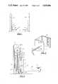
- FIG. 1is a simplified side elevation view of a two-column mechanism for lifting and lowering a load, especially vehicles and the like;
- FIG. 2is a detailed side elevation view of a part of the mechanism of FIG. 1 with portions shown in cross-section, other portions shown in full representation and yet other portions omitted for clarity;
- FIG. 3is an isometric side elevation view of a column of the mechanism shown in FIGS. 1 and 2 and illustrating the manner of inserting a lock pin prior to vehicle servicing activity;
- FIG. 4is a schematic diagram of a hydraulic circuit useful with the mechanism of FIGS. 1 and 2 and incorporating the apparatus of the invention
- FIG. 5is an end elevation view of a composite valve structure embodying the apparatus of the invention.
- FIG. 6is a top plan view of the valve of FIG. 5 taken along the plane 6--6 with portions shown in cross section and other portions shown in phantom, and;
- FIG. 7is a hydraulic schematic diagram of another embodiment of the invention.
- the inventive apparatus 10is shown in connection with a lift mechanism 11 as might be used for servicing the underside of automobiles and other vehicles.
- the mechanism 11is shown to include first and second vertically disposed support columns, 13 and 15 respectively, which may be rigidly affixed to the floor 17 of the service area or otherwise made generally nonmovable during service work.
- Each column 13, 15has slidably mounted thereon a movable carriage 19 including an attachment member 21 and a generally horizontally disposed support arm 23.
- Attached to the distal end 25 of the support arm 23is a lifting platform 27 which may be configured as a simple pad or as a pair of horizontally swingable arms which are adjustable in position to suit the arrangement of the vehicle being serviced.
- Lift mechanisms generally of the aforedescribed typeare in wide use for vehicle service.
- the carriage 19 of the first column 13is vertically movable by a first hydraulic cylinder 29 while that of the second column 15 is vertically movable by a second cylinder 31.
- a segment of the column 13is generally U-shaped in cross section and has a pair of outer flanges 33, each flange 33 having a plurality of vertically arranged, regularly spaced circular apertures 35 formed therein with their cylindrical axes disposed generally horizontally and in registry opposite those of the opposing flange 33.
- An aperture 37may be similarly formed in each attachment member 21 in a manner such that the operator of the mechanism may position the carriages 19 along their respective columns 13 or 15 to align the apertures 35 in the column flanges with the aperture 37 in the attachment member 21 to permit the insertion of a lock pin 39, thereby causing the carriages 19 to be supported during service and independent of the action of the hydraulic cylinders 29, 31.
- the attachment member 21is connected to the first end 41 of a chain 43, the second end 45 of which is anchored to the lower frame of the lift mechanism 11.
- a hydraulic cylinder 29is disposed within the lift mechanism 11, has its piston end 47 coupled to the lower frame or floor 17 and its rod end 49 coupled to a roller 51 mounted thereon for rotating movement.
- An arc 53 of the roller 51engages and supports a segment of the chain 43 so that by upwardly extending the rod end 49 as shown in FIG. 2, the carriage 19 is caused to lift the supported load.
- the apparatus 10 of the inventionis shown in conjunction with a hydraulic circuit 55 useful to controllably lift and lower the carriages 19 shown in FIG. 1 and it will be apparent to those of ordinary skill that this circuit 55 is only one of many with which the novel apparatus may be used.
- the circuitincludes a tank 57 for containing a quantity of hydraulic fluid and a source 59, such as a positive displacement pump, for delivering fluid under pressure.
- the source 59may conveniently be driven by a prime mover such as an electric motor (not shown).
- a relief valve 61is included for overpressure protection, while a pilot-operated bypass valve 63 permits fluid being delivered by the source 59 to be diverted to the tank 57 until the flow rate of fluid through the orifice 65 exceeds a predetermined value.
- the circuit 55also includes the first column cylinder 29 and the second column cylinder 31 connected in series and a manual lowering valve 67 for permitting a vehicle to be lowered upon the completion of service.
- a manually operated emergency lowering valve 69is preferably included to permit the load to be lowered in the event of a malfunction of one of the circuit components.
- the inventive apparatus 10is shown to include a first valve 71 and a second valve 73, each valve 71, 73 being of the two-position, two-way type and biased to the illustrated position by a spring 75, 77 in the absence of an appropriate differential pressure as described below.
- the first valve 71 and the second valve 73each include a first pilot port 79 and a second pilot port 81 for detecting a hydraulic pressure in a first sensing line and a second sensing line, 83 and 85 respectively.
- the first valve 71 and the second valve 73are each preferably constructed in a manner such that there must be a predetermined differential pressure between the pressure in the first sensing line 83 and that of the second sensing line 85 before the valve 71 or 73 may be shifted from the flow-permitting position shown to a flow-preventing position by overcoming the urging of the spring 75 or 77.
- the fluid present in line 87will, at some pressure depending upon the weight and position of the vehicle being serviced, be caused to flow to the piston end 47 of the first cylinder and the rod 89 will move upwardly. This causes fluid to be expelled from the rod end 49 of the first cylinder into the piston end 91 of the second cylinder and the rod 93 of the second cylinder is thereby also caused to move upwardly and the load is lifted.
- the inventive apparatusis embodied as a composite valve 95.
- the composite valve 95is shown to include a body 97 formed of a material having a strength and rigidity consistent with the pressure requirements of the application. In conventional hydraulic circuits, cast iron or machined steel are often used.
- the general techniques for making composite valvesare well known and will therefore be only briefly described.
- a plurality of spring retaining caps 99are threadably received in the body 97 and are sealed from leakage by O-rings 101.
- the valve 95also includes plugs 103 for closure of construction holes subsequent to drilling and for maintaining parts within the body 97.
- the first valve 71is shown to include a spool 105 sized to be in closely fitted, sliding engagement with its cylindrical bore 107 and includes a first spring chamber 109, within which is confined a biasing spring 75 which, during periods of repose, urges the spool downwardly as seen in FIG. 6.
- a port(not shown) is formed in the body for connecting line 111 to the valve, while a pilot passage 113 and connecting cross drilling 115 are formed in the spool 105 for providing a path by which the pressure in the first sensing line 83 may be communicated to the first pilot port 79.
- the second valve 73also includes a spool 117 sized for closely fitted, sliding engagement with its cylindrical bore 119 and a spring chamber 121 for confining a spring 123 which, during periods of repose, urges the spool 117 upwardly as seen in FIG. 6.
- a cross port 125 and restrictor orifice 127are provided for communicating that pressure at the second sensing line 85 to the second pilot ports 81 of both the first valve 71 and the second valve 73.
- the body 97also includes a port (not shown) for connecting line 129 to the lowering valve 67.
- An orifice plug 131is installed within the body 97 for restricting the flow rate of the fluid passing through the line 129 while threaded ports 133 and 135 are provided for connection to the piston end of the first cylinder and to the tank line respectively.
- the fluidis thereby diverted across the check valve 141 and since the lowering valve 67 is in the position shown, the fluid is prevented from flowing along the lines 111, 129.
- the fluid under pressureis therefore directed along the line 87 and into the piston end 47 of the first cylinder 29.
- the rod 89 of the first cylinder 29will move upwardly and with it, the associated carriage 19.
- Initial movementcauses fluid to be expelled from the rod end 49 of the first cylinder 29 and into the piston end 91 of the second cylinder 31, likewise causing a rise in pressure at that piston end 31 and upward movement of the associated carriage 19 so that the load may be uniformly lifted without substantial tilting.
- the apertures 37 in the attachment members 21are aligned with apertures 35 in their respective column flanges 33, the prime mover and source 59 are de-energized and the lock pins 39 are inserted through the flange and attachment member apertures 35, 37 to support the load in the absence of hydraulic pressure.
- the prime mover and source 59are again energized, thereby lifting the carriages 19 slightly so as to free the pins 39 of any load thereon.
- the prime mover and source 59are again de-energized, the pins 39 are removed and the lowering valve 67 is then manually manipulated leftward as shown in FIG. 4.
- the weight of the vehiclecauses fluid to be expelled from the piston end 91 of the second cylinder 31 to the rod end 49 of the first cylinder 29 and from the piston end 47 of the first cylinder 29 along the line 87, through the series-connected passages of the second valve 73 and the first valve 71 respectively, through the flow control orifice 131 and thence through the valve orifice 143 to tank 57.
- the vehicleis thereby controllably lowered to the floor.
- the inventive apparatus 10functions when either of the pins 39 have been inadvertently left in their loadretaining positions within the flanges 33. For example, if the lock pin 39 has been inadvertently left in the first column 13, powered by the first cylinder 29, manipulation of the valve 67 to the lowering position will permit the load to urge the rod 93 of the second cylinder 31 downwardly. The presence of orifice 143 in the lowering circuit will result in a back pressure in lines 129, 83, 87 notwithstanding that the rod 89 of cylinder 29 and its associated roller 51 and slackening chain 43 will lower of their own weight. Since the carriage 19, normally supported by cylinder 29, is prevented from moving, load tilting will result.
- the pressure in the first sensing line 83will rise to exceed that in the second sensing line 85 by some second predetermined value, and the second valve 73 is thereby caused to shift rightwardly as seen in FIG. 4, thereby preventing fluid from flowing along line 111.
- This activitythus requires the operator to again manipulate the valve 61 to the position shown and re-energize the prime mover and source 59 to cause slight upward movement of the rod 89 of the first cylinder 29, thereby permitting removal of the pin 39.
- first predetermined value and the second predetermined value of differential pressuremay be selected to be different one from the other, they will preferably be selected to be substantially the same one to the other. Further, it has been found that satisfactory operation will result if the displacement per unit length of stroke of the piston end 91 of the second cylinder 31 is substantially equal to that of the rod end 49 of the first cylinder 29.
- the valves 71, 73may preferably be constructed to be movable to a flow-preventing position when the pressure in the first sensing line 83 or the second sensing line 85, as the case may be, is approximately 85% greater than that in the other sensing line.
- this pressure differential percentage or ratiomay vary dramatically from that described, depending upon the relative diameters of the bores of the first and second cylinders 29, 31 and upon the relative diameters of the rods 89, 93 of those cylinders 29, 31.
- FIG. 7A valve of this type would employ a pair of centering springs 149 and would have unequal pilot pressure areas so that the valve 147 when in its first position as shown, permits flow through the passage 151 during normal operation. If sufficient differential pressure exists between the lines 83, 85, the valve 147 will be shifted in one direction or the other to a second or third position, i.e., to one of two possible flow blocking positions. Lines 83, 85, 87, 145 illustrate how this valve 147 may be connected in the circuit of FIG. 1 in lieu of valves 71, 73.
Landscapes
- Life Sciences & Earth Sciences (AREA)
- Engineering & Computer Science (AREA)
- Geology (AREA)
- Mechanical Engineering (AREA)
- Structural Engineering (AREA)
- Fluid-Pressure Circuits (AREA)
Abstract
Description
Claims (9)
Priority Applications (1)
| Application Number | Priority Date | Filing Date | Title |
|---|---|---|---|
| US06/789,516US4638886A (en) | 1985-10-21 | 1985-10-21 | Apparatus for disabling an obstructed lift mechanism |
Applications Claiming Priority (1)
| Application Number | Priority Date | Filing Date | Title |
|---|---|---|---|
| US06/789,516US4638886A (en) | 1985-10-21 | 1985-10-21 | Apparatus for disabling an obstructed lift mechanism |
Publications (1)
| Publication Number | Publication Date |
|---|---|
| US4638886Atrue US4638886A (en) | 1987-01-27 |
Family
ID=25147866
Family Applications (1)
| Application Number | Title | Priority Date | Filing Date |
|---|---|---|---|
| US06/789,516Expired - LifetimeUS4638886A (en) | 1985-10-21 | 1985-10-21 | Apparatus for disabling an obstructed lift mechanism |
Country Status (1)
| Country | Link |
|---|---|
| US (1) | US4638886A (en) |
Cited By (57)
| Publication number | Priority date | Publication date | Assignee | Title |
|---|---|---|---|---|
| US4856618A (en)* | 1987-08-25 | 1989-08-15 | Sugiyasu Industries Co., Ltd. | Mechanism for preventing a carriage of a system for lifting a vehicle for repair thereof from lowering |
| US4930971A (en)* | 1987-02-21 | 1990-06-05 | Wilson Frederick G | Lift platform for road vehicles and trailers |
| FR2650581A1 (en)* | 1989-08-07 | 1991-02-08 | Applic Hydro Meca Moderne | Improvements to elevator platforms (car lifts) |
| US5012898A (en)* | 1988-09-15 | 1991-05-07 | Hunter Engineering Company | Control system for vehicle lift racks |
| US5031726A (en)* | 1988-12-01 | 1991-07-16 | Sugiyasu Industries Co., Ltd. | Mechanism for automatically fixing a slide plate of a system for lifting a motor vehicle for repair thereof |
| US5110251A (en)* | 1989-01-17 | 1992-05-05 | Gray Ralph E | Hydraulic platform lift for truck trailers |
| US5411234A (en)* | 1992-03-24 | 1995-05-02 | Croon & Lucke Maschinenfabrik Gmbh | Stand for the storage of two-dimensional workpieces |
| US5421156A (en)* | 1991-01-25 | 1995-06-06 | Linde Aktiengesellschaft | Hydraulic drive system |
| US20040062628A1 (en)* | 2002-09-26 | 2004-04-01 | Alexander James C. | Apparatus and method for hydraulically controlling a vehicle restraint |
| US20090026020A1 (en)* | 2007-07-23 | 2009-01-29 | Akira Izuhara | Elevating device and control method thereof, and imaging apparatus |
| US20090242333A1 (en)* | 2005-10-11 | 2009-10-01 | Gerhard Finkbeiner | Method and Device for Monitoring a Lifting System |
| US20100186973A1 (en)* | 2009-01-26 | 2010-07-29 | Matt Flynn | Fire Sprinkler with Cutoff Valve, Tamper-Resistant Features and Status Indicator |
| US20110000745A1 (en)* | 2009-07-01 | 2011-01-06 | Richard Good | Motorcycle lift for car wash |
| US20110120737A1 (en)* | 2009-01-26 | 2011-05-26 | Matt Flynn | Fire Sprinkler with Ball-Type Cutoff Valve and Tamper-Resistant Features |
| US20120222916A1 (en)* | 2009-11-12 | 2012-09-06 | Roland Hornstein Gmbh & Co. Kg | Hydraulic Vehicle Lift System |
| CN104030032A (en)* | 2014-05-12 | 2014-09-10 | 杭州电子科技大学 | Auxiliary steel tube transferring device |
| US9078749B2 (en) | 2007-09-13 | 2015-07-14 | Georg Lutter | Truncated cone heart valve stent |
| CN105347251A (en)* | 2015-12-05 | 2016-02-24 | 安徽德摩新能源叉车股份有限公司 | Method for lifting four-direction forklift by using lifting device |
| CN105773574A (en)* | 2014-12-24 | 2016-07-20 | 鼎汉科技(厦门)有限公司 | Automatic film gripping mechanical hand |
| US9480559B2 (en) | 2011-08-11 | 2016-11-01 | Tendyne Holdings, Inc. | Prosthetic valves and related inventions |
| US9486306B2 (en) | 2013-04-02 | 2016-11-08 | Tendyne Holdings, Inc. | Inflatable annular sealing device for prosthetic mitral valve |
| CN106122161A (en)* | 2016-08-03 | 2016-11-16 | 广西科晟达机械制造有限公司 | A kind of scalable series connection cylinder |
| US9526611B2 (en) | 2013-10-29 | 2016-12-27 | Tendyne Holdings, Inc. | Apparatus and methods for delivery of transcatheter prosthetic valves |
| US9597181B2 (en) | 2013-06-25 | 2017-03-21 | Tendyne Holdings, Inc. | Thrombus management and structural compliance features for prosthetic heart valves |
| US9610159B2 (en) | 2013-05-30 | 2017-04-04 | Tendyne Holdings, Inc. | Structural members for prosthetic mitral valves |
| US9675454B2 (en) | 2012-07-30 | 2017-06-13 | Tendyne Holdings, Inc. | Delivery systems and methods for transcatheter prosthetic valves |
| US9828221B2 (en)* | 2012-09-01 | 2017-11-28 | Christoph Mohr | Scissors lift platform |
| US9827092B2 (en) | 2011-12-16 | 2017-11-28 | Tendyne Holdings, Inc. | Tethers for prosthetic mitral valve |
| US9895221B2 (en) | 2012-07-28 | 2018-02-20 | Tendyne Holdings, Inc. | Multi-component designs for heart valve retrieval device, sealing structures and stent assembly |
| US9988127B2 (en)* | 2015-04-10 | 2018-06-05 | Keppel Offshore & Marine Technology Centre Pte Ltd. | Vessel having a retractable cursor frame assembly |
| US9986993B2 (en) | 2014-02-11 | 2018-06-05 | Tendyne Holdings, Inc. | Adjustable tether and epicardial pad system for prosthetic heart valve |
| US10201419B2 (en) | 2014-02-05 | 2019-02-12 | Tendyne Holdings, Inc. | Apparatus and methods for transfemoral delivery of prosthetic mitral valve |
| US10327894B2 (en) | 2015-09-18 | 2019-06-25 | Tendyne Holdings, Inc. | Methods for delivery of prosthetic mitral valves |
| US10463494B2 (en) | 2013-04-02 | 2019-11-05 | Tendyne Holdings, Inc. | Prosthetic heart valve and systems and methods for delivering the same |
| US10463489B2 (en) | 2013-04-02 | 2019-11-05 | Tendyne Holdings, Inc. | Prosthetic heart valve and systems and methods for delivering the same |
| US10470877B2 (en) | 2016-05-03 | 2019-11-12 | Tendyne Holdings, Inc. | Apparatus and methods for anterior valve leaflet management |
| US10478293B2 (en) | 2013-04-04 | 2019-11-19 | Tendyne Holdings, Inc. | Retrieval and repositioning system for prosthetic heart valve |
| US10517728B2 (en) | 2014-03-10 | 2019-12-31 | Tendyne Holdings, Inc. | Devices and methods for positioning and monitoring tether load for prosthetic mitral valve |
| US10555718B2 (en) | 2013-10-17 | 2020-02-11 | Tendyne Holdings, Inc. | Apparatus and methods for alignment and deployment of intracardiac devices |
| US10610356B2 (en) | 2015-02-05 | 2020-04-07 | Tendyne Holdings, Inc. | Expandable epicardial pads and devices and methods for delivery of same |
| US10610358B2 (en) | 2015-12-28 | 2020-04-07 | Tendyne Holdings, Inc. | Atrial pocket closures for prosthetic heart valves |
| US10610354B2 (en) | 2013-08-01 | 2020-04-07 | Tendyne Holdings, Inc. | Epicardial anchor devices and methods |
| US10667905B2 (en) | 2015-04-16 | 2020-06-02 | Tendyne Holdings, Inc. | Apparatus and methods for delivery, repositioning, and retrieval of transcatheter prosthetic valves |
| US10786351B2 (en) | 2015-01-07 | 2020-09-29 | Tendyne Holdings, Inc. | Prosthetic mitral valves and apparatus and methods for delivery of same |
| US11027952B2 (en) | 2013-07-10 | 2021-06-08 | Stertil B.V. | Lifting system for lifting a vehicle and method for operating the lifting system |
| US11039921B2 (en) | 2016-06-13 | 2021-06-22 | Tendyne Holdings, Inc. | Sequential delivery of two-part prosthetic mitral valve |
| US11065116B2 (en) | 2016-07-12 | 2021-07-20 | Tendyne Holdings, Inc. | Apparatus and methods for trans-septal retrieval of prosthetic heart valves |
| US11090157B2 (en) | 2016-06-30 | 2021-08-17 | Tendyne Holdings, Inc. | Prosthetic heart valves and apparatus and methods for delivery of same |
| US11096782B2 (en) | 2015-12-03 | 2021-08-24 | Tendyne Holdings, Inc. | Frame features for prosthetic mitral valves |
| US11154399B2 (en) | 2017-07-13 | 2021-10-26 | Tendyne Holdings, Inc. | Prosthetic heart valves and apparatus and methods for delivery of same |
| US11179236B2 (en) | 2009-12-08 | 2021-11-23 | Colorado State University Research Foundation | Device and system for transcatheter mitral valve replacement |
| US11191639B2 (en) | 2017-08-28 | 2021-12-07 | Tendyne Holdings, Inc. | Prosthetic heart valves with tether coupling features |
| US11224510B2 (en) | 2013-04-02 | 2022-01-18 | Tendyne Holdings, Inc. | Prosthetic heart valve and systems and methods for delivering the same |
| US11648110B2 (en) | 2019-12-05 | 2023-05-16 | Tendyne Holdings, Inc. | Braided anchor for mitral valve |
| US11648114B2 (en) | 2019-12-20 | 2023-05-16 | Tendyne Holdings, Inc. | Distally loaded sheath and loading funnel |
| US11678980B2 (en) | 2020-08-19 | 2023-06-20 | Tendyne Holdings, Inc. | Fully-transseptal apical pad with pulley for tensioning |
| US11951002B2 (en) | 2020-03-30 | 2024-04-09 | Tendyne Holdings, Inc. | Apparatus and methods for valve and tether fixation |
Citations (7)
| Publication number | Priority date | Publication date | Assignee | Title |
|---|---|---|---|---|
| US2144892A (en)* | 1936-11-11 | 1939-01-24 | Automotive Prod Co Ltd | Fluid pressure operated jack |
| US2698517A (en)* | 1952-05-21 | 1955-01-04 | Kenneth F Witt | Automatic means to control and reverse fluid-operated cylinder-and-piston units |
| US3960286A (en)* | 1974-12-19 | 1976-06-01 | Allis-Chalmers Corporation | Automatic overload control for a counterbalanced lift truck |
| DE2752555A1 (en)* | 1976-11-26 | 1978-06-01 | Kempf & Co Ag | HYDRAULIC LIFTING DEVICE |
| US4457401A (en)* | 1982-04-09 | 1984-07-03 | Gilbert & Barker Manufacturing Co., Inc. | Above-the-floor hydraulic lift |
| US4567727A (en)* | 1982-12-06 | 1986-02-04 | Ingersoll-Rand Company | Proportioned hydraulic system |
| US4573663A (en)* | 1983-05-20 | 1986-03-04 | Hans Nussbaum | Lifting device, especially elevating platform for motor vehicles |
- 1985
- 1985-10-21USUS06/789,516patent/US4638886A/ennot_activeExpired - Lifetime
Patent Citations (7)
| Publication number | Priority date | Publication date | Assignee | Title |
|---|---|---|---|---|
| US2144892A (en)* | 1936-11-11 | 1939-01-24 | Automotive Prod Co Ltd | Fluid pressure operated jack |
| US2698517A (en)* | 1952-05-21 | 1955-01-04 | Kenneth F Witt | Automatic means to control and reverse fluid-operated cylinder-and-piston units |
| US3960286A (en)* | 1974-12-19 | 1976-06-01 | Allis-Chalmers Corporation | Automatic overload control for a counterbalanced lift truck |
| DE2752555A1 (en)* | 1976-11-26 | 1978-06-01 | Kempf & Co Ag | HYDRAULIC LIFTING DEVICE |
| US4457401A (en)* | 1982-04-09 | 1984-07-03 | Gilbert & Barker Manufacturing Co., Inc. | Above-the-floor hydraulic lift |
| US4567727A (en)* | 1982-12-06 | 1986-02-04 | Ingersoll-Rand Company | Proportioned hydraulic system |
| US4573663A (en)* | 1983-05-20 | 1986-03-04 | Hans Nussbaum | Lifting device, especially elevating platform for motor vehicles |
Cited By (100)
| Publication number | Priority date | Publication date | Assignee | Title |
|---|---|---|---|---|
| US4930971A (en)* | 1987-02-21 | 1990-06-05 | Wilson Frederick G | Lift platform for road vehicles and trailers |
| US4856618A (en)* | 1987-08-25 | 1989-08-15 | Sugiyasu Industries Co., Ltd. | Mechanism for preventing a carriage of a system for lifting a vehicle for repair thereof from lowering |
| US5012898A (en)* | 1988-09-15 | 1991-05-07 | Hunter Engineering Company | Control system for vehicle lift racks |
| US5031726A (en)* | 1988-12-01 | 1991-07-16 | Sugiyasu Industries Co., Ltd. | Mechanism for automatically fixing a slide plate of a system for lifting a motor vehicle for repair thereof |
| US5110251A (en)* | 1989-01-17 | 1992-05-05 | Gray Ralph E | Hydraulic platform lift for truck trailers |
| FR2650581A1 (en)* | 1989-08-07 | 1991-02-08 | Applic Hydro Meca Moderne | Improvements to elevator platforms (car lifts) |
| US5421156A (en)* | 1991-01-25 | 1995-06-06 | Linde Aktiengesellschaft | Hydraulic drive system |
| US5411234A (en)* | 1992-03-24 | 1995-05-02 | Croon & Lucke Maschinenfabrik Gmbh | Stand for the storage of two-dimensional workpieces |
| US20040062628A1 (en)* | 2002-09-26 | 2004-04-01 | Alexander James C. | Apparatus and method for hydraulically controlling a vehicle restraint |
| US7165486B2 (en)* | 2002-09-26 | 2007-01-23 | Spx Corporation | Apparatus and method for hydraulically controlling a vehicle restraint |
| US20090242333A1 (en)* | 2005-10-11 | 2009-10-01 | Gerhard Finkbeiner | Method and Device for Monitoring a Lifting System |
| US8708107B2 (en)* | 2005-10-11 | 2014-04-29 | Walter Finkbeiner Gmbh | Method for monitoring a lifting system |
| US20090026020A1 (en)* | 2007-07-23 | 2009-01-29 | Akira Izuhara | Elevating device and control method thereof, and imaging apparatus |
| US9078749B2 (en) | 2007-09-13 | 2015-07-14 | Georg Lutter | Truncated cone heart valve stent |
| US9730792B2 (en) | 2007-09-13 | 2017-08-15 | Georg Lutter | Truncated cone heart valve stent |
| US10456248B2 (en) | 2007-09-13 | 2019-10-29 | Georg Lutter | Truncated cone heart valve stent |
| US11213387B2 (en) | 2007-09-13 | 2022-01-04 | Georg Lutter | Truncated cone heart valve stent |
| US12383398B2 (en) | 2007-09-13 | 2025-08-12 | Georg Lutter | Truncated cone heart valve stent |
| US9254192B2 (en) | 2007-09-13 | 2016-02-09 | Georg Lutter | Truncated cone heart valve stent |
| US20100186973A1 (en)* | 2009-01-26 | 2010-07-29 | Matt Flynn | Fire Sprinkler with Cutoff Valve, Tamper-Resistant Features and Status Indicator |
| US20110120737A1 (en)* | 2009-01-26 | 2011-05-26 | Matt Flynn | Fire Sprinkler with Ball-Type Cutoff Valve and Tamper-Resistant Features |
| US20110000745A1 (en)* | 2009-07-01 | 2011-01-06 | Richard Good | Motorcycle lift for car wash |
| US20120222916A1 (en)* | 2009-11-12 | 2012-09-06 | Roland Hornstein Gmbh & Co. Kg | Hydraulic Vehicle Lift System |
| US11179236B2 (en) | 2009-12-08 | 2021-11-23 | Colorado State University Research Foundation | Device and system for transcatheter mitral valve replacement |
| US11135055B2 (en) | 2011-08-11 | 2021-10-05 | Tendyne Holdings, Inc. | Prosthetic valves and related inventions |
| US12059343B2 (en) | 2011-08-11 | 2024-08-13 | Tendyne Holdings, Inc. | Prosthetic valves and related inventions |
| US11484404B2 (en) | 2011-08-11 | 2022-11-01 | Tendyne Holdings, Inc. | Prosthetic valves and related inventions |
| US9480559B2 (en) | 2011-08-11 | 2016-11-01 | Tendyne Holdings, Inc. | Prosthetic valves and related inventions |
| US11311374B2 (en) | 2011-08-11 | 2022-04-26 | Tendyne Holdings, Inc. | Prosthetic valves and related inventions |
| US12121434B2 (en) | 2011-08-11 | 2024-10-22 | Tendyne Holdings, Inc. | Prosthetic valves and related inventions |
| US10639145B2 (en) | 2011-08-11 | 2020-05-05 | Tendyne Holdings, Inc. | Prosthetic valves and related inventions |
| US11123180B2 (en) | 2011-08-11 | 2021-09-21 | Tendyne Holdings, Inc. | Prosthetic valves and related inventions |
| US9833315B2 (en) | 2011-08-11 | 2017-12-05 | Tendyne Holdings, Inc. | Prosthetic valves and related inventions |
| US10617519B2 (en) | 2011-08-11 | 2020-04-14 | Tendyne Holdings, Inc. | Prosthetic valves and related inventions |
| US11364116B2 (en) | 2011-08-11 | 2022-06-21 | Tendyne Holdings, Inc. | Prosthetic valves and related inventions |
| US11382737B2 (en) | 2011-08-11 | 2022-07-12 | Tendyne Holdings, Inc. | Prosthetic valves and related inventions |
| US11123181B2 (en) | 2011-08-11 | 2021-09-21 | Tendyne Holdings, Inc. | Prosthetic valves and related inventions |
| US9827092B2 (en) | 2011-12-16 | 2017-11-28 | Tendyne Holdings, Inc. | Tethers for prosthetic mitral valve |
| US10952844B2 (en) | 2011-12-16 | 2021-03-23 | Tendyne Holdings, Inc. | Tethers for prosthetic mitral valve |
| US11759318B2 (en) | 2012-07-28 | 2023-09-19 | Tendyne Holdings, Inc. | Multi-component designs for heart valve retrieval device, sealing structures and stent assembly |
| US9895221B2 (en) | 2012-07-28 | 2018-02-20 | Tendyne Holdings, Inc. | Multi-component designs for heart valve retrieval device, sealing structures and stent assembly |
| US11090155B2 (en) | 2012-07-30 | 2021-08-17 | Tendyne Holdings, Inc. | Delivery systems and methods for transcatheter prosthetic valves |
| US9675454B2 (en) | 2012-07-30 | 2017-06-13 | Tendyne Holdings, Inc. | Delivery systems and methods for transcatheter prosthetic valves |
| US10219900B2 (en) | 2012-07-30 | 2019-03-05 | Tendyne Holdings, Inc. | Delivery systems and methods for transcatheter prosthetic valves |
| US9828221B2 (en)* | 2012-09-01 | 2017-11-28 | Christoph Mohr | Scissors lift platform |
| US11311379B2 (en) | 2013-04-02 | 2022-04-26 | Tendyne Holdings, Inc. | Prosthetic heart valve and systems and methods for delivering the same |
| US10463489B2 (en) | 2013-04-02 | 2019-11-05 | Tendyne Holdings, Inc. | Prosthetic heart valve and systems and methods for delivering the same |
| US9486306B2 (en) | 2013-04-02 | 2016-11-08 | Tendyne Holdings, Inc. | Inflatable annular sealing device for prosthetic mitral valve |
| US11224510B2 (en) | 2013-04-02 | 2022-01-18 | Tendyne Holdings, Inc. | Prosthetic heart valve and systems and methods for delivering the same |
| US10463494B2 (en) | 2013-04-02 | 2019-11-05 | Tendyne Holdings, Inc. | Prosthetic heart valve and systems and methods for delivering the same |
| US10478293B2 (en) | 2013-04-04 | 2019-11-19 | Tendyne Holdings, Inc. | Retrieval and repositioning system for prosthetic heart valve |
| US11364119B2 (en) | 2013-04-04 | 2022-06-21 | Tendyne Holdings, Inc. | Retrieval and repositioning system for prosthetic heart valve |
| US11617645B2 (en) | 2013-05-30 | 2023-04-04 | Tendyne Holdings, Inc. | Structural members for prosthetic mitral valves |
| US10405976B2 (en) | 2013-05-30 | 2019-09-10 | Tendyne Holdings, Inc. | Structural members for prosthetic mitral valves |
| US9610159B2 (en) | 2013-05-30 | 2017-04-04 | Tendyne Holdings, Inc. | Structural members for prosthetic mitral valves |
| US10595996B2 (en) | 2013-06-25 | 2020-03-24 | Tendyne Holdings, Inc. | Thrombus management and structural compliance features for prosthetic heart valves |
| US9597181B2 (en) | 2013-06-25 | 2017-03-21 | Tendyne Holdings, Inc. | Thrombus management and structural compliance features for prosthetic heart valves |
| US11471281B2 (en) | 2013-06-25 | 2022-10-18 | Tendyne Holdings, Inc. | Thrombus management and structural compliance features for prosthetic heart valves |
| US11027952B2 (en) | 2013-07-10 | 2021-06-08 | Stertil B.V. | Lifting system for lifting a vehicle and method for operating the lifting system |
| US10610354B2 (en) | 2013-08-01 | 2020-04-07 | Tendyne Holdings, Inc. | Epicardial anchor devices and methods |
| US11612480B2 (en) | 2013-08-01 | 2023-03-28 | Tendyne Holdings, Inc. | Epicardial anchor devices and methods |
| US12274615B2 (en) | 2013-08-01 | 2025-04-15 | Tendyne Holdings, Inc. | Epicardial anchor devices and methods |
| US11246562B2 (en) | 2013-10-17 | 2022-02-15 | Tendyne Holdings, Inc. | Apparatus and methods for alignment and deployment of intracardiac devices |
| US10555718B2 (en) | 2013-10-17 | 2020-02-11 | Tendyne Holdings, Inc. | Apparatus and methods for alignment and deployment of intracardiac devices |
| US9526611B2 (en) | 2013-10-29 | 2016-12-27 | Tendyne Holdings, Inc. | Apparatus and methods for delivery of transcatheter prosthetic valves |
| US11096783B2 (en) | 2013-10-29 | 2021-08-24 | Tendyne Holdings, Inc. | Apparatus and methods for delivery of transcatheter prosthetic valves |
| US10363135B2 (en) | 2013-10-29 | 2019-07-30 | Tendyne Holdings, Inc. | Apparatus and methods for delivery of transcatheter prosthetic valves |
| US11464628B2 (en) | 2014-02-05 | 2022-10-11 | Tendyne Holdings, Inc. | Expandable epicardial pads and devices and methods for delivery of same |
| US10201419B2 (en) | 2014-02-05 | 2019-02-12 | Tendyne Holdings, Inc. | Apparatus and methods for transfemoral delivery of prosthetic mitral valve |
| US11589985B2 (en) | 2014-02-05 | 2023-02-28 | Tendyne Holdings, Inc. | Apparatus and methods for transfemoral delivery of prosthetic mitral valve |
| US9986993B2 (en) | 2014-02-11 | 2018-06-05 | Tendyne Holdings, Inc. | Adjustable tether and epicardial pad system for prosthetic heart valve |
| US11045183B2 (en) | 2014-02-11 | 2021-06-29 | Tendyne Holdings, Inc. | Adjustable tether and epicardial pad system for prosthetic heart valve |
| US11382753B2 (en) | 2014-03-10 | 2022-07-12 | Tendyne Holdings, Inc. | Devices and methods for positioning and monitoring tether load for prosthetic mitral valve |
| US10517728B2 (en) | 2014-03-10 | 2019-12-31 | Tendyne Holdings, Inc. | Devices and methods for positioning and monitoring tether load for prosthetic mitral valve |
| CN104030032A (en)* | 2014-05-12 | 2014-09-10 | 杭州电子科技大学 | Auxiliary steel tube transferring device |
| CN105773574A (en)* | 2014-12-24 | 2016-07-20 | 鼎汉科技(厦门)有限公司 | Automatic film gripping mechanical hand |
| US10786351B2 (en) | 2015-01-07 | 2020-09-29 | Tendyne Holdings, Inc. | Prosthetic mitral valves and apparatus and methods for delivery of same |
| US10610356B2 (en) | 2015-02-05 | 2020-04-07 | Tendyne Holdings, Inc. | Expandable epicardial pads and devices and methods for delivery of same |
| US9988127B2 (en)* | 2015-04-10 | 2018-06-05 | Keppel Offshore & Marine Technology Centre Pte Ltd. | Vessel having a retractable cursor frame assembly |
| US10667905B2 (en) | 2015-04-16 | 2020-06-02 | Tendyne Holdings, Inc. | Apparatus and methods for delivery, repositioning, and retrieval of transcatheter prosthetic valves |
| US11523902B2 (en) | 2015-04-16 | 2022-12-13 | Tendyne Holdings, Inc. | Apparatus and methods for delivery, repositioning, and retrieval of transcatheter prosthetic valves |
| US10327894B2 (en) | 2015-09-18 | 2019-06-25 | Tendyne Holdings, Inc. | Methods for delivery of prosthetic mitral valves |
| US11318012B2 (en) | 2015-09-18 | 2022-05-03 | Tendyne Holdings, Inc. | Apparatus and methods for delivery of prosthetic mitral valve |
| US11096782B2 (en) | 2015-12-03 | 2021-08-24 | Tendyne Holdings, Inc. | Frame features for prosthetic mitral valves |
| CN105347251A (en)* | 2015-12-05 | 2016-02-24 | 安徽德摩新能源叉车股份有限公司 | Method for lifting four-direction forklift by using lifting device |
| US11464629B2 (en) | 2015-12-28 | 2022-10-11 | Tendyne Holdings, Inc. | Atrial pocket closures for prosthetic heart valves |
| US10610358B2 (en) | 2015-12-28 | 2020-04-07 | Tendyne Holdings, Inc. | Atrial pocket closures for prosthetic heart valves |
| US10470877B2 (en) | 2016-05-03 | 2019-11-12 | Tendyne Holdings, Inc. | Apparatus and methods for anterior valve leaflet management |
| US11253354B2 (en) | 2016-05-03 | 2022-02-22 | Tendyne Holdings, Inc. | Apparatus and methods for anterior valve leaflet management |
| US11039921B2 (en) | 2016-06-13 | 2021-06-22 | Tendyne Holdings, Inc. | Sequential delivery of two-part prosthetic mitral valve |
| US11090157B2 (en) | 2016-06-30 | 2021-08-17 | Tendyne Holdings, Inc. | Prosthetic heart valves and apparatus and methods for delivery of same |
| US11701226B2 (en) | 2016-06-30 | 2023-07-18 | Tendyne Holdings, Inc. | Prosthetic heart valves and apparatus and methods for delivery of same |
| US11065116B2 (en) | 2016-07-12 | 2021-07-20 | Tendyne Holdings, Inc. | Apparatus and methods for trans-septal retrieval of prosthetic heart valves |
| CN106122161A (en)* | 2016-08-03 | 2016-11-16 | 广西科晟达机械制造有限公司 | A kind of scalable series connection cylinder |
| US11154399B2 (en) | 2017-07-13 | 2021-10-26 | Tendyne Holdings, Inc. | Prosthetic heart valves and apparatus and methods for delivery of same |
| US11191639B2 (en) | 2017-08-28 | 2021-12-07 | Tendyne Holdings, Inc. | Prosthetic heart valves with tether coupling features |
| US11648110B2 (en) | 2019-12-05 | 2023-05-16 | Tendyne Holdings, Inc. | Braided anchor for mitral valve |
| US11648114B2 (en) | 2019-12-20 | 2023-05-16 | Tendyne Holdings, Inc. | Distally loaded sheath and loading funnel |
| US11951002B2 (en) | 2020-03-30 | 2024-04-09 | Tendyne Holdings, Inc. | Apparatus and methods for valve and tether fixation |
| US11678980B2 (en) | 2020-08-19 | 2023-06-20 | Tendyne Holdings, Inc. | Fully-transseptal apical pad with pulley for tensioning |
Similar Documents
| Publication | Publication Date | Title |
|---|---|---|
| US4638886A (en) | Apparatus for disabling an obstructed lift mechanism | |
| US10900825B2 (en) | Equalized hydraulic clamp force control | |
| US8322375B2 (en) | Control device and hydraulic pilot control | |
| JP3785159B2 (en) | Electrohydraulic lift control device for industrial trucks | |
| US2795346A (en) | Load grip side shift for lift trucks | |
| US4088151A (en) | Cylinder locking apparatus | |
| DE2433437C2 (en) | Control system for a hydraulic crane | |
| JPH0613881B2 (en) | Hydraulic control non-leakage braking lock valve | |
| US6220027B1 (en) | Stacker control | |
| US3866419A (en) | Integrated pressure compensated load sensing system | |
| US5546847A (en) | Hydraulic cylinder snubbing arrangement | |
| US3665810A (en) | Differential pressure holding valve | |
| DE102012101949A1 (en) | Lifting device of a truck | |
| US4338856A (en) | Dual pilot counterbalance valve | |
| US6786132B2 (en) | Control device for hydraulically operated hoisting mechanisms | |
| US3987703A (en) | Combined restrictor and dead engine lowering valve | |
| US3943825A (en) | Hydraulic control system for load supporting hydraulic motors | |
| EP3556722A1 (en) | Industrial truck with a lifting device | |
| US4023650A (en) | Hydraulic systems for two speed lifting | |
| US4466336A (en) | Control valve for hydraulic motor apparatus | |
| US3811363A (en) | Priority system for series-type hydraulic circuits | |
| CA1090677A (en) | Hydraulic valve assembly | |
| US4094228A (en) | Fluid system having load pressure equalizing valve assemblies | |
| DE60019500T2 (en) | Control device for cylinders | |
| DE2409523C3 (en) | Single-acting pressure cylinder |
Legal Events
| Date | Code | Title | Description |
|---|---|---|---|
| AS | Assignment | Owner name:STA-RITE INDUSTRIES, INC., 777 E. WISCONSIN AVENUE Free format text:ASSIGNMENT OF ASSIGNORS INTEREST.;ASSIGNOR:MARIETTA, WALTER E.;REEL/FRAME:004471/0098 Effective date:19851007 | |
| STCF | Information on status: patent grant | Free format text:PATENTED CASE | |
| FPAY | Fee payment | Year of fee payment:4 | |
| AS | Assignment | Owner name:DANFOSS A/S A CORPORATION OF THE KINGDOM OF DEN Free format text:ASSIGNMENT OF ASSIGNORS INTEREST.;ASSIGNOR:WEBSTER ELECTRIC COMPANY, INC., A DE CORPORATION;REEL/FRAME:006072/0669 Effective date:19911009 | |
| AS | Assignment | Owner name:DANFOSS A/S, DENMARK Free format text:NUNC PRO TUNC ASSIGNMENT;ASSIGNORS:WEBSTER ELECTRIC COMPANY, INC., A DE CORP.;STA-RITE INDUSTRIES, INC., A WI CORP.;FLUID CONTROLS, INC., A DE CORP.;REEL/FRAME:006196/0188 Effective date:19920514 | |
| FEPP | Fee payment procedure | Free format text:PAYOR NUMBER ASSIGNED (ORIGINAL EVENT CODE: ASPN); ENTITY STATUS OF PATENT OWNER: LARGE ENTITY | |
| FPAY | Fee payment | Year of fee payment:8 | |
| FPAY | Fee payment | Year of fee payment:12 | |
| AS | Assignment | Owner name:DANFOSS FLUID POWER A/S, DENMARK Free format text:ASSIGNMENT OF ASSIGNORS INTEREST;ASSIGNOR:DANFOSS A/S;REEL/FRAME:011052/0224 Effective date:19991129 |