US4638516A - Therapeutic bed support - Google Patents
Therapeutic bed supportDownload PDFInfo
- Publication number
- US4638516A US4638516AUS06/821,207US82120786AUS4638516AUS 4638516 AUS4638516 AUS 4638516AUS 82120786 AUS82120786 AUS 82120786AUS 4638516 AUS4638516 AUS 4638516A
- Authority
- US
- United States
- Prior art keywords
- longitudinally extending
- bed
- beams
- lever
- patient
- Prior art date
- Legal status (The legal status is an assumption and is not a legal conclusion. Google has not performed a legal analysis and makes no representation as to the accuracy of the status listed.)
- Expired - Lifetime
Links
- 230000001225therapeutic effectEffects0.000titleabstractdescription10
- 230000007246mechanismEffects0.000claimsabstractdescription27
- 235000010627Phaseolus vulgarisNutrition0.000claims1
- 244000046052Phaseolus vulgarisSpecies0.000claims1
- 230000010355oscillationEffects0.000abstractdescription2
- 230000003534oscillatory effectEffects0.000description7
- 230000006378damageEffects0.000description2
- 230000000694effectsEffects0.000description2
- 230000003028elevating effectEffects0.000description2
- 230000004048modificationEffects0.000description2
- 238000012986modificationMethods0.000description2
- 238000003466weldingMethods0.000description2
- 208000027418Wounds and injuryDiseases0.000description1
- 230000004075alterationEffects0.000description1
- 208000014674injuryDiseases0.000description1
- 230000009467reductionEffects0.000description1
- 238000002560therapeutic procedureMethods0.000description1
Images


Classifications
- A—HUMAN NECESSITIES
- A61—MEDICAL OR VETERINARY SCIENCE; HYGIENE
- A61G—TRANSPORT, PERSONAL CONVEYANCES, OR ACCOMMODATION SPECIALLY ADAPTED FOR PATIENTS OR DISABLED PERSONS; OPERATING TABLES OR CHAIRS; CHAIRS FOR DENTISTRY; FUNERAL DEVICES
- A61G7/00—Beds specially adapted for nursing; Devices for lifting patients or disabled persons
- A61G7/002—Beds specially adapted for nursing; Devices for lifting patients or disabled persons having adjustable mattress frame
- A61G7/008—Beds specially adapted for nursing; Devices for lifting patients or disabled persons having adjustable mattress frame tiltable around longitudinal axis, e.g. for rolling
- A—HUMAN NECESSITIES
- A61—MEDICAL OR VETERINARY SCIENCE; HYGIENE
- A61G—TRANSPORT, PERSONAL CONVEYANCES, OR ACCOMMODATION SPECIALLY ADAPTED FOR PATIENTS OR DISABLED PERSONS; OPERATING TABLES OR CHAIRS; CHAIRS FOR DENTISTRY; FUNERAL DEVICES
- A61G7/00—Beds specially adapted for nursing; Devices for lifting patients or disabled persons
- A61G7/002—Beds specially adapted for nursing; Devices for lifting patients or disabled persons having adjustable mattress frame
- A61G7/012—Beds specially adapted for nursing; Devices for lifting patients or disabled persons having adjustable mattress frame raising or lowering of the whole mattress frame
- A—HUMAN NECESSITIES
- A61—MEDICAL OR VETERINARY SCIENCE; HYGIENE
- A61G—TRANSPORT, PERSONAL CONVEYANCES, OR ACCOMMODATION SPECIALLY ADAPTED FOR PATIENTS OR DISABLED PERSONS; OPERATING TABLES OR CHAIRS; CHAIRS FOR DENTISTRY; FUNERAL DEVICES
- A61G7/00—Beds specially adapted for nursing; Devices for lifting patients or disabled persons
- A61G7/05—Parts, details or accessories of beds
- A61G7/057—Arrangements for preventing bed-sores or for supporting patients with burns, e.g. mattresses specially adapted therefor
- A61G7/0573—Arrangements for preventing bed-sores or for supporting patients with burns, e.g. mattresses specially adapted therefor with mattress frames having alternately movable parts
Definitions
- This inventionrelates generally to an apparatus for treating an immobilized patient receiving oscillatory motion therapy.
- itrelates to a therapeutic treatment platform which provides controlled oscillatory movement to a bed support means having a patient disposed thereon.
- the oscillating mechanismincludes a slip-clutch device which prevents injury to the oscillating mechanism when the bed support means is locked in its horizontal position and the oscillating mechanism is not deactivated or disengaged.
- An oscillating therapeutic treatment bedhaving an elevating mechanism which provides lowering of the patient support platform close to the floor level and tilting.
- the oscillating mechanismincludes an automatic release means which will release the bed when it is in its horizontal position and which likewise can be set to reengage the oscillating mechanism with the bed patient support means. During operation the release mechanism may be deactivated in any oscillatory position of the bed but it will not disengage until the bed reaches its horizontal position.
- the oscillating mechanismincludes an eccentric adjusting means which will vary the arc in which the bed rotates.
- the bedfurther includes a locking means which automatically locks the patient support means in its horizontal position when the back supporting portion of the bed is raised.
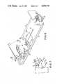
- FIG. 1is a partial view showing the elevating mechanism for the of the therapeutic treatment bed.
- FIG. 2is a partial view showing the lifting mechanism in its immediate position.
- FIG. 3is a partial view showing the lifting mechanism in its upper-most position.
- FIG. 4is a partial view showing the lifting mechanism in a tilted position.
- FIG. 5is a partial view showing the oscillating mechanism of the bed.
- FIG. 5ashows the slip clutch mechanism
- FIG. 6shows the locking means which prevents rotation of the patient support means when the back of the patient support means is raised.
- FIG. 7shows the adjusting means which varies the arc in which the patient support means oscillates.
- FIG. 8is a partial view showing a portion of the oscillating mechanism of the bed.
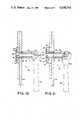
- FIG. 9is a cross-sectional side view of the releasing means of the oscillating mechanism in its locked position.
- FIG. 10is a cross-sectional side view of the releasing means in its released position before it is disengaged.
- FIG. 11is a cross-sectional side view of the releasing means in its disengaged position.
- FIG. 12is a partial exploded view of the releasing means.
- the undercarriage 10 of a therapeutic treatment bedincludes a base 11 which is supported by wheel members 12, 13, 14 and 15 which allow the base and bed to be moved to a desired location.
- the wheel membersmay be of the locking type to retain the bed in a stationary position.
- the base 11includes a plurality of longitudinally extending and transversely spaced beams 16 and 17 which are secured together by transverse beams 18 and 19.
- the longitudinal beams 16 and 17are spaced apart for a reason which will be explained hereinafter.
- a bed support means 20is provided for supporting the patient support platform 54.
- the bed support means 20includes a plurality of longitudinally extending beams 21, 22, 23, 24, 25 and 26. At the outer ends of the beams 21 and 22 is mounted an upright support post 28. At the end of beams 25 and 26 is mounted another upright support post 27. A pivot bearing 29 is secured to the upright post 27. Another pivot axis 30 is secured to the upright post 28.
- Patient support platform 54which is shown in FIG. 6 is mounted upon these pivot bearings. The patient support platform 54 is pivotally mounted on these pivot bearings 29 and 30 by pivot pins 59 and 58 respectively.
- the beams 21 and 25are connected by the beam 23 and the beams 22 and 26 are connected by the beam 24.
- the transverse spacing between the beams 21, 23, 25 and 22, 24 and 26is such that they may be positioned between the beams 16 and 17.
- the beams 23 and 24may rest upon the transverse beams 18 and 19 in their lower most position.
- the bed support means 20may be lowered very close to the ground support through the unique arrangement in spacing of the beams and as a result of the lifting means described below.
- lifting means 31 and 32are provided to raise and lower the bed support means 20 relative to the base 11.
- Lifting means 31includes a power screw 33 which is driven by an electric motor 34.
- the lifting means 32is identical and includes a power screw 33a and an electric motor 34a. As will be apparent, each of the power screws may be retracted or extended upon actuation of the electric motors which are of the reversable type.
- the lifting means 31 as shown in FIGS. 1-4includes a strap 35 which is secured to the beam 17 and another strap 35a secured to the beam 16. These straps are secured to these beams by suitable means such as welding.
- a lever 36is pivotally attached to the strap 35.
- Another lever 37is pivotally attached to the other strap 35a.
- a lever 38is pivotally attached to the lever 36 and another lever 39 is likewise pivotally attached to the lever 37.
- the levers 38 and 39are rigidly connected to a rotating shaft 40 by suitable means such as welding.
- the shaft 40is rotatably mounted with support brackets 41 and 42 which are secured to the beam members 21 and 22 respectively. Straps 43 and 44 are rigidly connected to the rotatably mounted shaft 40.
- the power screw 33is pivotally mounted with the straps 43 and 44. Since the other end of the power screw 33 is connected with the bed support means 20 actuation of the power screw means which results in its extension or retraction pivots the shaft 40 which in turn translates motion to the levers 36, 37,
- This lifting meansincludes straps 45 and 46 which are rigidly secured to the longitudinal beams 17 and 16 respectively.
- Levers 47 and 48are pivotally mounted with the straps 45 and 46 respectively.
- the opposite ends of the levers 47 and 48are rigidly connected to rotating shaft 49.
- the rotating shaft 49is pivotally mounted with brackets 50 and 51 which are rigidly secured to beams 25 and 26 respectively.
- Straps 52 and 53are rigidly secured with the rotating shaft 49 to provide rotating motion thereto.
- One end of the power screw 33ais pivotally connected with the straps 52 and 53 and the other end is connected with the bed support means.
- Suitable control switches on a control panelare provided to selectively and separately operate the lifting means 31 and 32. Accordingly, the bed support means 20 may be lowered, raised or tilted to provide a desired position for a patient support means which is mounted upon the pivot bearings 29 and 30.
- FIGS. 2, 3 and 4The raising and lowering of the patient support means 20 is shown in FIGS. 2, 3 and 4.
- the bed support means 20is in an intermediate position between its lower most and upper most positions.
- the power screws 33 and 33aare in their fully extended position which raises the bed support means 20 to its upper most position.
- the bed support meansis tilted by extending the power screw 33a and retracting the power screw 33. This is utilized to position the patient in an inclined position.
- the bed support means 20may be lowered such that the beams 23 and 24 rest upon the beams 18 and 19. In this position a patient (not shown) on a patient support mcans is closest to the ground support such that that person may be more easily removed from the bed.
- the patient support platform 54includes a generally rectangular frame 55 connected to vertical posts 56 and 57. Pivot pins 58 and 59 are secured to the vertical posts 56 and 57 respectively and are adapted to be rotatably positioned upon the pivot bearings 29 and 30 for pivotally mounting the patient support platform 54 on the bed support means 20.
- Keel means 60is connected to the vertical support post 56 to provide a counterbalance for the patient support platform. Suitable weights may be positioned on the keel means 60 to prevent overturning of the bed which might cause a patient to fall therefrom.
- the patient support platform 54includes a first support surface 61 which has a hatch means 62.
- the hatch means 62allows access to a patient from below the patient when a patient is not easily moved.
- a second support surface 63is provided to complete the patient support platform.
- the second support surface 63is pivotally mounted relative to the rectangular frame 55 so that it may be raised as shown in FIG. 6 or lowered to a horizontal position whereby it is in the same plane as the first support surface 61.
- the purpose for pivotally mounting the second support surface 63is to allow it to be partially raised so that the patient may be raised and inclined in the bed.
- Secured at one side of the frame 54is a bracket 64 having a plurality of slots positioned there along.
- a similar bracket(not shown) is positioned opposite the bracket 64.
- Levers 66 and 69are pivotally mounted at one end to the second support surface 63 and a bar 67 as secured at their other end to interconnect them. Bar 67 extends beyond the outer sides of the levers 69 and 66 so that it may be selectively inserted into notches in the brackets such as notch 68 to retain the second support surface in a desired position and angle relative to the first support surface 61.
- the second support surface 63is fixedly mounted to frame member 69 so that pivoting of the second support surface 63 causes rotation of the frame member 69.
- Strap 70is rigidly secured to the frame member 69 and a bifurcated bracket 71 is pivotally connected to the strap 70.
- Rod member 72is connected to the bifurcated bracket 71 and also connected to sliding pin 72a.
- the pin 72ais slidably mounted in a sleeve 73 positioned in the vertical post 56.
- a drive motor 74(FIGS. 1 and 5) which provides rotation to the patient support platform 24 so that it will oscillate in a predetermined arc.
- the drive motor 74includes a reduction gear box 75 which has a rotating output shaft 75a as shown in FIG. 5.
- Attached to the rotating output shaft 75ais a slip clutch 77 which includes journal 76 on which is rotatably mounted portion 76a of lever 78.
- the slip clutchprevents damage to the motor 74 and gear box 75 when overloaded and is also used to determine the amount of counterbalancing weight added to the keel.
- the shaft 76is pivotally connected to journal 76a on lever 78.
- the lever 78is connected to lever 79 by connecting means 80.
- the lever 79is in turn rotatably connected to pin 81 as best shown in FIG. 5.
- the pin 81is secured with the patient support platform 54 spaced from the center of rotation of the pivot pin 59.
- rotation of the lever 77will cause reciprocation of the lever 78 which motion will be translated to the lever 79 when the connecting means 80 rigidly connects the levers 78 and 79 in the position as shown in FIG. 8 to provide oscillation of the patient support platform 54.
- the arc in which the patient support platform 54 oscillatesis determined by the position of the pin 81 relative to the pivot pin 59.
- the pin 81is eccentrically mounted about another pin 82 which is releasably secured in the pin support bracket 83.
- the pin support bracket 83includes two portions 84 and 85 which compressably hold the pin 82 to prevent its rotation. This is achieved by a screw tightener 86 which may be used to clamp the two portions and prevent the pin 82 from rotating or to release the two portions and allow rotation of the pin 82.
- Rotation of the pin 82changes the position of the pin 81 which is rotatably connected with the lever 79. This effects the arc in which the patient support platform 54 rotates.
- an adjusting bracket 87having a plurality of notches 88, 89, 90 and 91.
- Secured to the upper portion 83is bifurcated bracket 92 through which extends a pin 93.
- a locking member 94Pivotally mounted with the pin 93 is a locking member 94 which may be selectively positioned in notches 88, 89, 90 or 91. This is achieved by loosening the screw tightener 86 and rotating the pin 82 to position the notches so that the locking member 94 may be selectively positioned in the notch which is at the position of notch 90 as shown in FIG. 7.
- the connecting means 80is best shown in FIGS. 8, 9, 10, 11 and 12.
- the connecting means 80includes a releasable locking means 95 which selectively engages and locks the levers 78 and 79 in the position shown in FIG. 8 or releases them as shown in FIG. 11 so that the lever 79 is not rigidly connected to the lever 78.
- the purpose of the releasable locking meansis to allow the patient support platform 54 to be disconnected from the drive motor 74 so that support platform 54 will oscillate independently of the drive motor 74.
- the lever 79fits in a slot 96 (FIG. 11). Slot 96 receives the lever 79 as shown in FIGS. 9 and 10 to rigidly lock them together.
- the releasable locking means 95 as best shown in FIG. 12includes an eye bolt 97 having threaded portion 97b which is connected to threaded portion 98b of end cap 98 which engages member 99 which is rigidly secured to the lever 79.
- the reduced portion 98a of the end cap 98extends through an aperture 100 in the member 99.
- a sleeve 101is rigidly secured with the lever 78 and extends through the aperture 102 in the lever 79.
- Lever 79slides upon the sleeve 101 from its locked position as shown in FIGS. 9 and 10 to its released position as shown in FIG. 11.
- the eye bolt 97extends through the sleeve 101 and through bracket 103.
- the bracket 103 as shown in FIG. 12is rigidly secured to lever 78 and is bifurcated member with straps 104 and 105.
- Strap 105includes a slot 106a and the strap 104 also includes an identical slot 106. Slots 106 and 106a slidably receive a pin 107 having apertures 107a.
- Cotter keys 113 and 114 and washers 115 and 116retain the pin 107 in position when it extends through slots 106 and 106a and apertures 109a, 97a and 109b.
- the releasing and engaging lever 108includes a camming surface 109 and locking surfaces 109c, the purposes of which are more fully explained hereinafter.
- Positioned on the eye bolt 97is a washer 110.
- a first spring member 111is positioned about the eye bolt 97 and to engage bracket 103 and washer 110 to bias the washer 110 against the camming surface 109.
- a second spring member 112is positioned about the eye bolt 97 to engage the member 99 and the bracket 103.
- the spring 112acts against the member 99 to bias the lever 79 to the position as shown in FIG. 11.
- Spring 111acts to move the lever 78 and 79 to their locking position as shown in FIGS. 9 and 10.
- the springs 111 and 112have preselected force values to maintain the releasable locking means 95 in its position as shown in FIG. 9 when the releasing and engaging lever 108 is in its engaged setting and to allow release of the releasable locking means 95 when the lever 108 is moved to the releasing setting as shown in FIGS. 10 and 11.
- the releasable locking meanswill not allow release of the lever 79 from the lever 78 until patient support platform 54 is in its substantially horizontal rest position and there are no frictional forces being applied to the levers 78 and 79. This is achieved by carefully selecting the forces of the springs 111 and 112 as follows.
- the lever 108When it is desired to release the lever 78 and 79 so that the bed will remain in a horizontal position, the lever 108 is moved to the releasing setting as shown in FIGS. 10 and 11. In this case the camming surface 109 allows the washer 110 to be moved to the right as shown in FIGS. 10 and 11 to release some of the stored energy in the spring 111. In this position, the spring 112 applies a greater force than does the spring 111. However, the lever 79 is not released from the lever 78 due to the frictional forces between the contacting surfaces of the levers 78 and 79. The frictional forces occur from the weight of the patient support platform 54. Accordingly, the levers 78 and 79 will not be released from each other as shown in FIG.
- lever 109may be released or engaged when the patient support platform is in any position but it will retain the levers 78 and 79 in their locked position as shown in FIG. 10 until the bed reaches a substantially horizontal position where the spring 112 will cause the lever 79 to pop out of the slot 96. Thereafter reciprocation of the lever 78 will no longer apply any force to the lever 79 since lever 78 and 79 are allowed to rotate relative to each other about pin member 97.
- the lever 108When it is desired to reconnect the levers 78 and 79 to the locked position as shown in FIGS. 8, 9 and 10, the lever 108 is moved to its engaged setting as shown in FIG. 9. However, the lever 79 will not be positioned into the slot 96 until the levers 78 and 79 are properly aligned during the reciprocating stroke of the lever 78. Accordingly, the releasable locking means 95 can be set to automatically release the levers 78 and 79 and likewise automatically connect them at the horizontal position of the patient support platform when frictional forces are relieved. The operator can also relieve the friction force between the levers 78 and 79 and manually release or connect them at any position.
- releasable locking means 95Without the releasable locking means 95, it would be difficult to releasably connect the levers 78 and 79 and this generally would have to be done when the patient support platform 54 was in its substantially horizontal position. It should be understood that the lever 78 moves very slowly so this would require an attendant to wait until the levers 78 and 79 were properly aligned before they were released or reconnected.
- the releasable locking means 95allows attendant to engage or disengage the lever 108 at any time so that the levers 78 and 79 will automatically be connected or disconnected as desired. A large amount of physical strength is not required to perform this task notwithstanding the great weight of the bed, particularly with the patient positioned thereon.
Landscapes
- Health & Medical Sciences (AREA)
- Nursing (AREA)
- Life Sciences & Earth Sciences (AREA)
- Animal Behavior & Ethology (AREA)
- General Health & Medical Sciences (AREA)
- Public Health (AREA)
- Veterinary Medicine (AREA)
- Invalid Beds And Related Equipment (AREA)
Abstract
Description
Claims (5)
Priority Applications (2)
| Application Number | Priority Date | Filing Date | Title |
|---|---|---|---|
| US06/821,207US4638516A (en) | 1981-01-19 | 1986-01-22 | Therapeutic bed support |
| US06/910,485US4763643A (en) | 1981-01-19 | 1986-09-23 | Arc changing apparatus for a therapeutic oscillating bed |
Applications Claiming Priority (2)
| Application Number | Priority Date | Filing Date | Title |
|---|---|---|---|
| US06/226,118US4432353A (en) | 1981-01-19 | 1981-01-19 | Kinetic treatment platform |
| US06/821,207US4638516A (en) | 1981-01-19 | 1986-01-22 | Therapeutic bed support |
Related Parent Applications (1)
| Application Number | Title | Priority Date | Filing Date |
|---|---|---|---|
| US06567224Continuation | 1983-12-30 |
Related Child Applications (1)
| Application Number | Title | Priority Date | Filing Date |
|---|---|---|---|
| US06/910,485DivisionUS4763643A (en) | 1981-01-19 | 1986-09-23 | Arc changing apparatus for a therapeutic oscillating bed |
Publications (1)
| Publication Number | Publication Date |
|---|---|
| US4638516Atrue US4638516A (en) | 1987-01-27 |
Family
ID=26920223
Family Applications (1)
| Application Number | Title | Priority Date | Filing Date |
|---|---|---|---|
| US06/821,207Expired - LifetimeUS4638516A (en) | 1981-01-19 | 1986-01-22 | Therapeutic bed support |
Country Status (1)
| Country | Link |
|---|---|
| US (1) | US4638516A (en) |
Cited By (26)
| Publication number | Priority date | Publication date | Assignee | Title |
|---|---|---|---|---|
| US4868937A (en)* | 1986-05-02 | 1989-09-26 | Ethos Medical Research Limited | Therapeutic bed |
| US4890604A (en)* | 1987-09-14 | 1990-01-02 | Nelson Dorand N | Traction assembly |
| US4935974A (en)* | 1989-10-06 | 1990-06-26 | Dick Stebbins | Nursing home bed tilt apparatus |
| US5136742A (en)* | 1989-10-06 | 1992-08-11 | Dick Stebbins | Nursing home bed tilt apparatus |
| US5317769A (en)* | 1992-11-10 | 1994-06-07 | Hill-Rom Company, Inc. | Hospital bed |
| US5606754A (en) | 1989-03-09 | 1997-03-04 | Ssi Medical Services, Inc. | Vibratory patient support system |
| US5983429A (en)* | 1994-02-15 | 1999-11-16 | Stacy; Richard B. | Method and apparatus for supporting and for supplying therapy to a patient |
| US6230344B1 (en)* | 1999-06-09 | 2001-05-15 | M.C. Healthcare Products Inc. | Adjustable bed |
| US6385801B1 (en)* | 2000-03-13 | 2002-05-14 | Kabushikikaisha Nihon M.D.M. | Rocking bed |
| US6499160B2 (en)* | 1997-08-08 | 2002-12-31 | Hill-Rom Services, Inc. | Hospital bed |
| US20030126683A1 (en)* | 1998-06-26 | 2003-07-10 | Hill-Rom Services, Inc. | Hospital bed |
| US6609260B2 (en) | 2000-03-17 | 2003-08-26 | Hill-Rom Services, Inc. | Proning bed and method of operating the same |
| US20040168253A1 (en)* | 1999-04-21 | 2004-09-02 | Hill-Rom Services, Inc. | Proning bed |
| US6817363B2 (en) | 2000-07-14 | 2004-11-16 | Hill-Rom Services, Inc. | Pulmonary therapy apparatus |
| US20050172405A1 (en)* | 2002-09-06 | 2005-08-11 | Menkedick Douglas J. | Hospital bed |
| US20060191538A1 (en)* | 2001-10-22 | 2006-08-31 | Map Medizin-Technologie Gmbh | Application device for breathing mask arrangement |
| US20070169271A1 (en)* | 1995-01-03 | 2007-07-26 | Allen E D | Hospital bed and mattress having a retractable foot section |
| US20080202527A1 (en)* | 2007-01-23 | 2008-08-28 | Kci Licensing, Inc. | Providing automated or manual guidance on dynamic patient positioning based on measured variables for ventilation control |
| US20110047703A1 (en)* | 2009-08-31 | 2011-03-03 | Jean-Francois Tarsaud | Lateral tilt device |
| US8286282B2 (en) | 1995-08-04 | 2012-10-16 | Hill-Rom Services, Inc. | Bed frame and mattress synchronous control |
| US20150099614A1 (en)* | 2013-10-07 | 2015-04-09 | Daniel R. Tekulve | Portable rehab station |
| US9009893B2 (en) | 1999-12-29 | 2015-04-21 | Hill-Rom Services, Inc. | Hospital bed |
| US9089459B2 (en) | 2013-11-18 | 2015-07-28 | Völker GmbH | Person support apparatus |
| US9572742B2 (en)* | 2015-01-15 | 2017-02-21 | Jack Larry Chadwick | Relaxation device |
| US12042453B2 (en) | 2019-02-26 | 2024-07-23 | Hill-Rom Services, Inc. | Patient positioning apparatus and mattress |
| RU228422U1 (en)* | 2024-04-17 | 2024-08-28 | Общество с ограниченной ответственностью "Медтехника Реботек" (ООО "Медтехника-Р") | LEVER FOR RAISING AND LOWERING A SECTION OF A MEDICAL DEVICE |
Citations (7)
| Publication number | Priority date | Publication date | Assignee | Title |
|---|---|---|---|---|
| US3222693A (en)* | 1963-01-14 | 1965-12-14 | Borg Warner | Adjustable bed |
| US3434165A (en)* | 1967-07-03 | 1969-03-25 | Vickers Ltd | Hospital bed |
| US3686696A (en)* | 1970-01-07 | 1972-08-29 | American Hospital Supply Corp | Hospital beds |
| US4230100A (en)* | 1978-07-26 | 1980-10-28 | Moon Derryl E | Chiropractic table |
| US4345344A (en)* | 1980-04-08 | 1982-08-24 | Centre De Recherche Industrielle Du Quebec | Hospital bed |
| US4401110A (en)* | 1980-08-12 | 1983-08-30 | Standex International Corporation | Patient treatment table |
| US4425673A (en)* | 1980-12-01 | 1984-01-17 | B-W Health Products, Inc. | Lifting system for adjustable hospital bed |
- 1986
- 1986-01-22USUS06/821,207patent/US4638516A/ennot_activeExpired - Lifetime
Patent Citations (8)
| Publication number | Priority date | Publication date | Assignee | Title |
|---|---|---|---|---|
| US3222693A (en)* | 1963-01-14 | 1965-12-14 | Borg Warner | Adjustable bed |
| US3434165A (en)* | 1967-07-03 | 1969-03-25 | Vickers Ltd | Hospital bed |
| US3434165B1 (en)* | 1967-07-03 | 1983-12-06 | ||
| US3686696A (en)* | 1970-01-07 | 1972-08-29 | American Hospital Supply Corp | Hospital beds |
| US4230100A (en)* | 1978-07-26 | 1980-10-28 | Moon Derryl E | Chiropractic table |
| US4345344A (en)* | 1980-04-08 | 1982-08-24 | Centre De Recherche Industrielle Du Quebec | Hospital bed |
| US4401110A (en)* | 1980-08-12 | 1983-08-30 | Standex International Corporation | Patient treatment table |
| US4425673A (en)* | 1980-12-01 | 1984-01-17 | B-W Health Products, Inc. | Lifting system for adjustable hospital bed |
Cited By (53)
| Publication number | Priority date | Publication date | Assignee | Title |
|---|---|---|---|---|
| US4868937A (en)* | 1986-05-02 | 1989-09-26 | Ethos Medical Research Limited | Therapeutic bed |
| US4890604A (en)* | 1987-09-14 | 1990-01-02 | Nelson Dorand N | Traction assembly |
| US6415814B1 (en) | 1989-03-09 | 2002-07-09 | Hill-Rom Services, Inc. | Vibratory patient support system |
| US5606754A (en) | 1989-03-09 | 1997-03-04 | Ssi Medical Services, Inc. | Vibratory patient support system |
| US20050034764A1 (en)* | 1989-03-09 | 2005-02-17 | Hanh Barry D. | Patient support system |
| US6098222A (en) | 1989-03-09 | 2000-08-08 | Hill-Rom Company, Inc. | Vibratory patient support system |
| US6820640B2 (en) | 1989-03-09 | 2004-11-23 | Hill-Rom Services, Inc. | Vibratory patient support system |
| US4935974A (en)* | 1989-10-06 | 1990-06-26 | Dick Stebbins | Nursing home bed tilt apparatus |
| US5136742A (en)* | 1989-10-06 | 1992-08-11 | Dick Stebbins | Nursing home bed tilt apparatus |
| US5317769A (en)* | 1992-11-10 | 1994-06-07 | Hill-Rom Company, Inc. | Hospital bed |
| US5983429A (en)* | 1994-02-15 | 1999-11-16 | Stacy; Richard B. | Method and apparatus for supporting and for supplying therapy to a patient |
| US7523515B2 (en) | 1995-01-03 | 2009-04-28 | Hill-Rom Services, Inc. | Hospital bed and mattress having a retractable foot section |
| US20070169271A1 (en)* | 1995-01-03 | 2007-07-26 | Allen E D | Hospital bed and mattress having a retractable foot section |
| US8286282B2 (en) | 1995-08-04 | 2012-10-16 | Hill-Rom Services, Inc. | Bed frame and mattress synchronous control |
| US6499160B2 (en)* | 1997-08-08 | 2002-12-31 | Hill-Rom Services, Inc. | Hospital bed |
| US6691347B2 (en) | 1997-08-08 | 2004-02-17 | Hill-Rom Services, Inc. | Hospital bed |
| US20030126683A1 (en)* | 1998-06-26 | 2003-07-10 | Hill-Rom Services, Inc. | Hospital bed |
| US6862759B2 (en) | 1998-06-26 | 2005-03-08 | Hill-Rom Services, Inc. | Hospital bed |
| US20040168253A1 (en)* | 1999-04-21 | 2004-09-02 | Hill-Rom Services, Inc. | Proning bed |
| US7137160B2 (en) | 1999-04-21 | 2006-11-21 | Hill-Rom Services, Inc. | Proning bed |
| US6230344B1 (en)* | 1999-06-09 | 2001-05-15 | M.C. Healthcare Products Inc. | Adjustable bed |
| US10251797B2 (en) | 1999-12-29 | 2019-04-09 | Hill-Rom Services, Inc. | Hospital bed |
| US9009893B2 (en) | 1999-12-29 | 2015-04-21 | Hill-Rom Services, Inc. | Hospital bed |
| US6385801B1 (en)* | 2000-03-13 | 2002-05-14 | Kabushikikaisha Nihon M.D.M. | Rocking bed |
| US6609260B2 (en) | 2000-03-17 | 2003-08-26 | Hill-Rom Services, Inc. | Proning bed and method of operating the same |
| US20040006821A1 (en)* | 2000-03-17 | 2004-01-15 | Hill-Rom Services, Inc. | Hospital bed |
| US6862761B2 (en) | 2000-03-17 | 2005-03-08 | Hill-Rom Services, Inc. | Hospital proning bed |
| US6817363B2 (en) | 2000-07-14 | 2004-11-16 | Hill-Rom Services, Inc. | Pulmonary therapy apparatus |
| US20050011518A1 (en)* | 2000-07-14 | 2005-01-20 | Hill-Rom Services, Inc. | Pulmonary therapy apparatus |
| US7343916B2 (en) | 2000-07-14 | 2008-03-18 | Hill-Rom Services, Inc. | Pulmonary therapy apparatus |
| US7931607B2 (en) | 2000-07-14 | 2011-04-26 | Hill-Rom Services, Inc. | Pulmonary therapy apparatus |
| US20060191538A1 (en)* | 2001-10-22 | 2006-08-31 | Map Medizin-Technologie Gmbh | Application device for breathing mask arrangement |
| US7296312B2 (en) | 2002-09-06 | 2007-11-20 | Hill-Rom Services, Inc. | Hospital bed |
| US7520006B2 (en) | 2002-09-06 | 2009-04-21 | Hill-Rom Services, Inc. | Hospital bed including moveable foot portion |
| US20050172405A1 (en)* | 2002-09-06 | 2005-08-11 | Menkedick Douglas J. | Hospital bed |
| US7669263B2 (en) | 2002-09-06 | 2010-03-02 | Hill-Rom Services, Inc. | Mattress assembly including adjustable length foot |
| US7703158B2 (en) | 2002-09-06 | 2010-04-27 | Hill-Rom Services, Inc. | Patient support apparatus having a diagnostic system |
| US7506390B2 (en) | 2002-09-06 | 2009-03-24 | Hill-Rom Services, Inc. | Patient support apparatus having controller area network |
| US20080010748A1 (en)* | 2002-09-06 | 2008-01-17 | Menkedick Douglas J | Patient support apparatus having controller area network |
| US7406731B2 (en) | 2002-09-06 | 2008-08-05 | Holl-Rom Services, Inc. | Hospital bed |
| USRE43532E1 (en) | 2002-09-06 | 2012-07-24 | Hill-Rom Services, Inc. | Hospital bed |
| US8202226B2 (en) | 2007-01-23 | 2012-06-19 | Kci Licensing, Inc. | Providing automated or manual guidance on dynamic patient positioning based on measured variables for ventilation control |
| US20080202527A1 (en)* | 2007-01-23 | 2008-08-28 | Kci Licensing, Inc. | Providing automated or manual guidance on dynamic patient positioning based on measured variables for ventilation control |
| US8429774B2 (en) | 2009-08-31 | 2013-04-30 | Hill-Rom Industries Sa | Lateral tilt device |
| US8601622B1 (en) | 2009-08-31 | 2013-12-10 | Hill-Rom Industries S.A. | Patient support apparatus including a lateral tilt device |
| US20110047703A1 (en)* | 2009-08-31 | 2011-03-03 | Jean-Francois Tarsaud | Lateral tilt device |
| US20150099614A1 (en)* | 2013-10-07 | 2015-04-09 | Daniel R. Tekulve | Portable rehab station |
| US9398995B2 (en)* | 2013-10-07 | 2016-07-26 | Daniel R. Tekulve | Portable rehab station |
| US10206847B1 (en)* | 2013-10-07 | 2019-02-19 | Med-Mizer, Inc. | Portable rehab station |
| US9089459B2 (en) | 2013-11-18 | 2015-07-28 | Völker GmbH | Person support apparatus |
| US9572742B2 (en)* | 2015-01-15 | 2017-02-21 | Jack Larry Chadwick | Relaxation device |
| US12042453B2 (en) | 2019-02-26 | 2024-07-23 | Hill-Rom Services, Inc. | Patient positioning apparatus and mattress |
| RU228422U1 (en)* | 2024-04-17 | 2024-08-28 | Общество с ограниченной ответственностью "Медтехника Реботек" (ООО "Медтехника-Р") | LEVER FOR RAISING AND LOWERING A SECTION OF A MEDICAL DEVICE |
Similar Documents
| Publication | Publication Date | Title |
|---|---|---|
| US4763643A (en) | Arc changing apparatus for a therapeutic oscillating bed | |
| US4432353A (en) | Kinetic treatment platform | |
| US4638516A (en) | Therapeutic bed support | |
| US4175550A (en) | Therapeutic bed | |
| US4097939A (en) | Hospital bed | |
| US3820176A (en) | Patient handling table | |
| US6427263B1 (en) | Device for moving patients | |
| US4987622A (en) | Self-operated stand up support apparatus | |
| US4045078A (en) | Tilting therapeutic table | |
| US5720059A (en) | Tilting mechanism for bed | |
| US5816763A (en) | Apparatus for transporting mobility devices and method therefor | |
| EP1810650A2 (en) | Patient support apparatus having auto contour | |
| US4790716A (en) | Device for handling a wheelchair | |
| KR100338243B1 (en) | Locking device | |
| US4941799A (en) | Displaceable support for wheelchair | |
| US4726730A (en) | Device for handling a wheelchair | |
| US3711876A (en) | Tilt bed | |
| EP0026167B1 (en) | Operation table for big animals | |
| EP0739194B1 (en) | A hoist for handling a patient and a feet-supporting plate assembly to be used in connection with a hoist for handling a patient | |
| US4131801A (en) | X-ray cradle top with tilting mechanism | |
| US5022388A (en) | Patient table apparatus | |
| US5094228A (en) | Apparatus for treatment of the back | |
| US2500544A (en) | Bedpan vehicle | |
| US4809685A (en) | Chiropractic table lever-locking mechanism | |
| US6003168A (en) | Person movement apparatus |
Legal Events
| Date | Code | Title | Description |
|---|---|---|---|
| STCF | Information on status: patent grant | Free format text:PATENTED CASE | |
| AS | Assignment | Owner name:NBC BANK-SAN ANTONIO, NATIONAL ASSOCIATION (FORMER Free format text:SECURITY INTEREST;ASSIGNOR:KINETIC CONCEPTS, INC., A TX. CORP.;REEL/FRAME:004648/0915 Effective date:19861217 | |
| AS | Assignment | Owner name:KINETIC CONCEPTS, INC., 3440 E. HOUSTON ST., SAN A Free format text:RELEASED BY SECURED PARTY;ASSIGNOR:NBC BANK-SAN ANTONIO;REEL/FRAME:004766/0858 Effective date:19870911 Owner name:FIRST NATIONAL BANK OF BOSTON, THE Free format text:SECURITY INTEREST;ASSIGNOR:KINETIC CONCEPTS, INC.,;REEL/FRAME:004767/0211 Effective date:19870915 Owner name:KINETIC CONCEPTS, INC., A CORP. OF TX,TEXAS Free format text:RELEASED BY SECURED PARTY;ASSIGNOR:NBC BANK-SAN ANTONIO;REEL/FRAME:004766/0858 Effective date:19870911 | |
| FPAY | Fee payment | Year of fee payment:4 | |
| AS | Assignment | Owner name:FIRST NATIONAL BANK OF BOSTON, THE, 100 FEDERAL ST Free format text:SECURITY INTEREST;ASSIGNOR:KINETIC CONCEPTS, INC.;REEL/FRAME:005634/0613 Effective date:19910301 | |
| AS | Assignment | Owner name:BANK OF AMERICA NATIONAL TRUST AND SAVINGS ASSOCIA Free format text:SECURITY INTEREST;ASSIGNOR:KINETIC CONCEPTS, INC., A CORPORATION OF TX;REEL/FRAME:006005/0316 Effective date:19911120 Owner name:KINETIC CONCEPTS, INC., TEXAS Free format text:RELEASED BY SECURED PARTY;ASSIGNOR:FIRST NATIONAL BANK OF BOSTON, THE;REEL/FRAME:006005/0332 Effective date:19911121 Owner name:KINETIC CONCEPTS, INC., TEXAS Free format text:RELEASED BY SECURED PARTY;ASSIGNOR:NBC BANK - SAN ANTONIO, NATIONAL ASSOCIATION;REEL/FRAME:006005/0344 Effective date:19911104 | |
| FEPP | Fee payment procedure | Free format text:PAYOR NUMBER ASSIGNED (ORIGINAL EVENT CODE: ASPN); ENTITY STATUS OF PATENT OWNER: LARGE ENTITY | |
| AS | Assignment | Owner name:BANK OF AMERICA NATIONAL TRUST AND SAVINGS ASSOCIA Free format text:AMENDED NOTICE OF SECURITY INTEREST;ASSIGNOR:KINETIC CONCEPTS, INC. CORPORATION - DELAWARE;REEL/FRAME:006826/0140 Effective date:19931229 | |
| AS | Assignment | Owner name:BANK OF AMERICA NATIONAL TRUST AND SAVINGS ASSOCIA Free format text:SECURITY INTEREST;ASSIGNOR:KINETIC CONCEPTS, INC.;REEL/FRAME:006874/0480 Effective date:19930217 | |
| FPAY | Fee payment | Year of fee payment:8 | |
| AS | Assignment | Owner name:KINETIC CONCEPTS, INC., TEXAS Free format text:RELEASE OF SECURITY INTEREST;ASSIGNOR:BANK OF AMERICA NATIONAL TRUST AND SAVINGS ASSOCIATION;REEL/FRAME:008773/0934 Effective date:19950508 | |
| AS | Assignment | Owner name:BANK OF AMERICA NATIONAL TRUST AND SAVINGS ASSOCIA Free format text:SECURITY AGREEMENT;ASSIGNORS:KINETIC CONCEPTS, INC. (A TEXAS CORPORATION);KCI HOLDING COMPANY, (A DE CORP.);KCI NEW TECHNOLOGIES, INC. (A DE CORP.);AND OTHERS;REEL/FRAME:008896/0699 Effective date:19971103 | |
| FPAY | Fee payment | Year of fee payment:12 | |
| AS | Assignment | Owner name:KCI LICENSING, INC., TEXAS Free format text:ASSIGNMENT OF ASSIGNORS INTEREST;ASSIGNOR:KINETIC CONCEPTS, INC.;REEL/FRAME:012219/0150 Effective date:20010919 | |
| AS | Assignment | Owner name:MORGAN STANLEY & CO. INCORPORATED, NEW YORK Free format text:SECURITY INTEREST;ASSIGNORS:KINETIC CONCEPTS, INC.;KCI USA, INC.;KCI HOLDING COMPANY, INC.;AND OTHERS;REEL/FRAME:014624/0681 Effective date:20030811 | |
| AS | Assignment | Owner name:KCI LICENSING, INC., TEXAS Free format text:RELEASE BY SECURED PARTY;ASSIGNOR:BANK OF AMERICA NATIONAL TRUST & SAVINGS ASSOCIATION;REEL/FRAME:019605/0526 Effective date:20070727 | |
| AS | Assignment | Owner name:KCI LICENSING, INC., TEXAS Free format text:RELEASE BY SECURED PARTY;ASSIGNOR:MORGAN STANLEY & CO., INCORPORATED;REEL/FRAME:019617/0356 Effective date:20070731 Owner name:KCI LICENSING, INC.,TEXAS Free format text:RELEASE BY SECURED PARTY;ASSIGNOR:MORGAN STANLEY & CO., INCORPORATED;REEL/FRAME:019617/0356 Effective date:20070731 |