US4638432A - Apparatus for controlling the transfer of interrupt signals in data processors - Google Patents
Apparatus for controlling the transfer of interrupt signals in data processorsDownload PDFInfo
- Publication number
- US4638432A US4638432AUS06/598,469US59846984AUS4638432AUS 4638432 AUS4638432 AUS 4638432AUS 59846984 AUS59846984 AUS 59846984AUS 4638432 AUS4638432 AUS 4638432A
- Authority
- US
- United States
- Prior art keywords
- interrupt
- input signal
- unit
- input signals
- signal
- Prior art date
- Legal status (The legal status is an assumption and is not a legal conclusion. Google has not performed a legal analysis and makes no representation as to the accuracy of the status listed.)
- Expired - Fee Related
Links
Images


Classifications
- G—PHYSICS
- G06—COMPUTING OR CALCULATING; COUNTING
- G06F—ELECTRIC DIGITAL DATA PROCESSING
- G06F13/00—Interconnection of, or transfer of information or other signals between, memories, input/output devices or central processing units
- G06F13/14—Handling requests for interconnection or transfer
- G06F13/20—Handling requests for interconnection or transfer for access to input/output bus
- G06F13/24—Handling requests for interconnection or transfer for access to input/output bus using interrupt
Definitions
- the present inventionrelates to input signal handling apparatus in particular to such apparatus for handling input signals to a computer and more particularly, but not exclusively, to apparatus for handling "interrupt" input signals.
- interruptsare graded according to their urgency and in particular may be categorised as “immediate”--that is requiring urgent attention--and “non-immediate”--that is requiring handling by a special program but not likely to result in a serious malfunction if the handling of it is delayed.
- Such actionmay occur unnecessarily on numerous occasions if the number of non-immediate interrupts to be handled is high in comparison to the number of immediate interrupts. Such unnecessary actions impede the efficient running of the computer and, particularly when the computer is required to operate in real-time, reduce the loading which may be placed thereon.
- One object of the present inventionis to provide input signal handling apparatus which is capable of pre-sorting interrupt signals and which has a higher level of security in comparison with the previously known system.
- immediate input signalmeans an input signal which requires urgent handling by a computer system.
- non-immediate input signalis an input signal which does not require urgent handling.
- two input signal unitsare provided one of which is selected as an active unit and the other of which is selected as a monitoring unit, and each of which has a plurality of inputs arranged for connection to a respective source of input signals, an output for connection to a data processor, a data store which stores data defining a flag in respect of each signal received on one of said inputs and control means which compares each signal so received and stored with presettable criteria which determine whether the received signal is an immediate input signal (as hereinbefore defined) and, if so, the active input signal unit causes data defining all of the flags currently stored to be passed to its respective output and the subsequent erasure of the data defining those flags whereby all input signals received and stored as aforesaid are transferred to a connected computer and on occurence of an immediate input signal (as hereinbefore defined) the monitoring input signal unit monitors an output of the active input signal unit to determine whether that unit has acted to transfer data in
- the selection of one of the units as active and the other as monitoringis reversed from time-to-time by action of a connected data processor.
- Each unit of the apparatusmay have a plurality of outputs each of which is arranged for connection to a respective one of a plurality of computers and the control means may be presettable to select to which of the outputs the data is passed.
- an input signal unithas a plurality of inputs each arranged for connection to a respective source of input signals, an ouput of the unit is arranged for connection to a data processor, a first data store of the unit stores data defining a flag in respect of each signal received on one of said inputs and control means of the unit compares each signal so received and stored with presettable criteria which determine whether the received signal is an immediate input signal (as hereinbefore defined) and, if so, causes data defining all of the flags currently stored to be transferred from the first data store to a temporary data store and thence to the output, the data presented at the output by the temporary data store being looped back to inputs of the first data store to cause erasure of the data defining those flags which have been presented at the output such that only those flags representing received input signals whose occurrence has been successfully signalled to a connected data processor are erased.
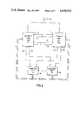
- FIG. 1is a block schematic diagram of one unit of the apparatus in use with multiple computers
- FIG. 2is a connection diagram showing the interconnection of the two units of the apparatus to multiple computers.
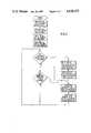
- FIGS. 3 to 7show logic flowcharts of programs which taken together provide for operation of the apparatus embodiment shown in FIGS. 1 and 2.
- an interrupt logic unit 1handles interrupt signals generated by telephone exchange apparatus for example (not shown) which signals are received by way of a number of inputs 20 to 2x.
- the interrupt signalsare stored by the interrupt logic unit 1 and forwarded to one of N computer units 30 to 3N either immediately (immediate interrupt) or subsequently (non-immediate interrupt).
- each interrupt received as a signal on one of the inputs 20 to 2xis latched in an interrupt store 2 and is passed to control logic 3 (which may be a microprocessor) by way of a data highway 4.
- the control logic 3is arranged to be preprogrammed by the operating system of the multicomputer arrangement (30 to 3N) with data defining which interrupts are enabled and which of the interrupts should give rise to an immediate interruption of the software running in one of the computer units.
- the aforementioned operating systemalso designates which of the N computers will next handle interrupts.
- interrupts which are received by the interrupt logic 1are latched into the interrupt store 2 and are compared by the control logic 3 with the above criteria.
- An interrupt which is not enabled as aforesaidis handled by the control logic 3 as a non-immediate interrupt.
- This facilitypermits unused ones of the inputs 20 to 2x to be left for future expansion, and unconnected, any such apparent interrupt signal being due possibly to "noise".
- Some of the inputs 20 to 2xmay also be programmed as not enabled when for example apparatus to which they are connected has been removed for servicing. However, if on comparison in the control logic 3 the particular interrupt is determined as enabled a further comparison is carried out to determine if the input is an immediate interrupt. If the interrupt is non-immediate no further action is taken by the control logic 3 for the time being.
- control logic 3forwards an immediate interrupt signal to the previously designated one of the computer units 30 to 3N on a respective one of the leads 60 to 6N.
- the computer selected (say) 30On receipt of an interrupt signal the computer selected (say) 30 stops running its present program and calls an interrupt handling program.
- the interrupt handling programinitiates a read function which causes data to be transferred from the interrupt store 2 to the read register 5 and latches the data in the read register 5 to prevent alteration of the data while the computer is performing the read which causes the contents of the register to be transferred over the data bus 9 which is an input/output bus of the computer system.
- the data set in the interrupt store 2On completion of the read function the data set in the interrupt store 2 is cleared.
- a number of read registers 5may be provided and each may be addressed in turn by the interrupt handling program of the computer 30.
- control logicdisables the AND gates 80 to 8x and removes the latching signal received at the inputs 20 to 2x are now similarly handled.
- the multicomputer operating systemwill access the control logic 3 by way of the data bus 9 and change the data which designates the computer to be interrupted.
- control logic 3may be arranged to commence a timeout once it has applied an interrupt signal on one of the leads 60 to 6N. If the read register 5 has not been addressed before expiry of the timeout then the control logic 3 is arranged to attempt to interrupt all of the computers 30 to 3N in turn until a response is received. It is here noted that the timeout may be pre-set in the control logic 3 by the operating system by way of the data bus 9. It should also be noted that if the timeout above expires the control logic 3 will generate interrupt data of its own into the interrupt store which the computer unit successfully interrupted will read as part of its read function and which will cause an indication of the failure if required.
- FIG. 2for security purposes the interrupt logic unit 1 of FIG. 1 is duplicated, each of the logic units having the ability to interrupt any of the computer units 30 to 3N by way of respective interrupt leads 60 to 6N.
- the interrupt logic unit on the left of FIG. 2 and its associated interruptsare designated as for FIG. 1 whilst their equivalents on the right of FIG. 2 are similarly designated with the addition of a prime (').
- Each of the interrupt logic units 1operates in an identical manner as far as determining the validity and status of an input signal received on one of the inputs 20 to 2x is concerned.
- one of the logic units, say, 1is designated by the multi-computer operating system as the "working" unit whilst the other logic unit 1' is designated as the "stand-by" unit. It will be appreciated that the operating system may periodically interchange the designation of the two units.
- the two logic units 1are interconnected with two respective additional leads 11, 12 which are used in the following manner; when the working logic unit 1 generates an interrupt on one of the leads 60 to 6N it will forward a signal on the lead 11 and when the logic unit 1 detects that the read register (5 of FIG. 1) has been read it forwards a signal on the lead 12.
- the standby interrupt logic unit 1On receipt of an immediate interrupt the standby interrupt logic unit 1' commences a timeout and monitors the lead 11. This timeout may be preset by the operating system as previously described. The interrupt logic unit 1 having received the same immediate interrupt will proceed to pass a signal to one of the leads 60 to 6N and at the same time signals the lead 11.
- the signal on the lead 11is detected by the interrupt logic unit 1' which then cancels the timeout.
- the interrupt logic unit 1'now starts a further timeout and monitors the lead 12.
- the interrupt logic unit 1detects that the interrupted computer unit, say, 30 has read the interrupt data from the register 5 it forwards a signal on the lead 12 which is detected by the interrupt logic unit 1' which then cancels the second timeout thus commpleting the monitoring sequence.
- the interrupt logic unit 1'will generate an interrupt itself and will cause an additional interrupt flag indicating the failure of the "working" interrupt logic unit 1.
- the control logic 3 of the interrupt logic units 1are arranged to receive a periodic ⁇ refresh ⁇ signal by way of the data bus 9. This periodic refresh signal which should be provided by the multi-computer operating system is used to reset a timeout in the control logic 3. If such a signal is not received prior to the expiry of the timeout the control logic generates an immediate interrupt.
- the interrupt logic unit 1may also be arranged to cause a hardware alarm system (not shown) to operate.
- interrupt logic units 1, 1'are periodically reversed by the multi-computer operating system to ensure that each is fully functional should one be required to act as the sole interrupt logic unit if the other is temporarily unavailable.
- F/W--FirmwareSoftware in Programmable Read Only Memory on an Interrupt Unit
- FIG. 3shows the sequence for setting up immediate/ masked (i.e. non-immediate) interrupt status information in the worker logic unit and the standby logic unit. This is the above-mentioned pre-programming by the operating system of the multicomputer arrangement (30 to 3N) of the control logic 3 of the logic units and is under control of the above listed PUS software.
- FIG. 4shows the setting of immediate and non-immediate interrupts in the interrupt register 2, and the "read and clear” sequence for the interrupt register 2 and read register 5. These operations are performed by the interrupt unit (logic unit) hardware under control of the above-listed IU Firmware and PUS Software.
- FIG. 5shows the sequence for setting and changing over the worker/standby status of the logic units under control of the PUS Software.
- FIG. 6shows the sequence for selecting the lowest priority CPU, i.e. which of the computers 30 to 3N will next handle interrupts, under control of the PUS Software.
- FIG. 7shows the sequence for monitoring the worker logic unit by the standby logic unit. This is performed by the IU (logic unit) hardware and firmware in the standby logic unit.
Landscapes
- Engineering & Computer Science (AREA)
- Theoretical Computer Science (AREA)
- Physics & Mathematics (AREA)
- General Engineering & Computer Science (AREA)
- General Physics & Mathematics (AREA)
- Bus Control (AREA)
- Hardware Redundancy (AREA)
Abstract
Description
Claims (5)
Applications Claiming Priority (2)
| Application Number | Priority Date | Filing Date | Title |
|---|---|---|---|
| GB8310003 | 1983-04-13 | ||
| GB838310003AGB8310003D0 (en) | 1983-04-13 | 1983-04-13 | Input signal handling apparatus |
Publications (1)
| Publication Number | Publication Date |
|---|---|
| US4638432Atrue US4638432A (en) | 1987-01-20 |
Family
ID=10541038
Family Applications (1)
| Application Number | Title | Priority Date | Filing Date |
|---|---|---|---|
| US06/598,469Expired - Fee RelatedUS4638432A (en) | 1983-04-13 | 1984-04-09 | Apparatus for controlling the transfer of interrupt signals in data processors |
Country Status (8)
| Country | Link |
|---|---|
| US (1) | US4638432A (en) |
| EP (1) | EP0125797B1 (en) |
| AU (1) | AU562586B2 (en) |
| CA (1) | CA1212478A (en) |
| DE (1) | DE3466813D1 (en) |
| GB (2) | GB8310003D0 (en) |
| NZ (1) | NZ207809A (en) |
| ZA (1) | ZA842713B (en) |
Cited By (7)
| Publication number | Priority date | Publication date | Assignee | Title |
|---|---|---|---|---|
| US4816990A (en)* | 1986-11-05 | 1989-03-28 | Stratus Computer, Inc. | Method and apparatus for fault-tolerant computer system having expandable processor section |
| US4959781A (en)* | 1988-05-16 | 1990-09-25 | Stardent Computer, Inc. | System for assigning interrupts to least busy processor that already loaded same class of interrupt routines |
| US5291608A (en)* | 1990-02-13 | 1994-03-01 | International Business Machines Corporation | Display adapter event handler with rendering context manager |
| US5517624A (en)* | 1992-10-02 | 1996-05-14 | Compaq Computer Corporation | Multiplexed communication protocol between central and distributed peripherals in multiprocessor computer systems |
| US20020152419A1 (en)* | 2001-04-11 | 2002-10-17 | Mcloughlin Michael | Apparatus and method for accessing a mass storage device in a fault-tolerant server |
| US6816934B2 (en) | 2000-12-22 | 2004-11-09 | Hewlett-Packard Development Company, L.P. | Computer system with registered peripheral component interconnect device for processing extended commands and attributes according to a registered peripheral component interconnect protocol |
| US20060150005A1 (en)* | 2004-12-21 | 2006-07-06 | Nec Corporation | Fault tolerant computer system and interrupt control method for the same |
Families Citing this family (4)
| Publication number | Priority date | Publication date | Assignee | Title |
|---|---|---|---|---|
| CH670714A5 (en)* | 1986-10-22 | 1989-06-30 | Bbc Brown Boveri & Cie | |
| CA2026770A1 (en)* | 1989-11-03 | 1991-05-04 | John A. Landry | Multiprocessor interrupt control |
| US5247685A (en)* | 1989-11-03 | 1993-09-21 | Compaq Computer Corp. | Interrupt handling in an asymmetric multiprocessor computer system |
| US5435001A (en)* | 1993-07-06 | 1995-07-18 | Tandem Computers Incorporated | Method of state determination in lock-stepped processors |
Citations (5)
| Publication number | Priority date | Publication date | Assignee | Title |
|---|---|---|---|---|
| US3895353A (en)* | 1972-05-03 | 1975-07-15 | Robin Edward Dalton | Data processing systems |
| US3908099A (en)* | 1974-09-27 | 1975-09-23 | Gte Automatic Electric Lab Inc | Fault detection system for a telephone exchange |
| GB2032149A (en)* | 1978-09-08 | 1980-04-30 | Fujitsu Ltd | Transferring from Working to Standby Processor on Fault |
| US4371754A (en)* | 1980-11-19 | 1983-02-01 | Rockwell International Corporation | Automatic fault recovery system for a multiple processor telecommunications switching control |
| US4412280A (en)* | 1978-08-31 | 1983-10-25 | United Technologies Corporation | Complementary commands in fail-operational, fail-safe multi-computer control system |
Family Cites Families (3)
| Publication number | Priority date | Publication date | Assignee | Title |
|---|---|---|---|---|
| US3716837A (en)* | 1971-04-22 | 1973-02-13 | Ibm | Interrupt handling |
| US4268906A (en)* | 1978-12-22 | 1981-05-19 | International Business Machines Corporation | Data processor input/output controller |
| US4330826A (en)* | 1980-02-05 | 1982-05-18 | The Bendix Corporation | Synchronizer and synchronization system for a multiple computer system |
- 1983
- 1983-04-13GBGB838310003Apatent/GB8310003D0/enactivePending
- 1984
- 1984-04-09USUS06/598,469patent/US4638432A/ennot_activeExpired - Fee Related
- 1984-04-11NZNZ207809Apatent/NZ207809A/enunknown
- 1984-04-12AUAU26765/84Apatent/AU562586B2/ennot_activeCeased
- 1984-04-12CACA000451839Apatent/CA1212478A/ennot_activeExpired
- 1984-04-12ZAZA842713Apatent/ZA842713B/enunknown
- 1984-04-13GBGB08409719Apatent/GB2139786B/ennot_activeExpired
- 1984-04-13EPEP84302530Apatent/EP0125797B1/ennot_activeExpired
- 1984-04-13DEDE8484302530Tpatent/DE3466813D1/ennot_activeExpired
Patent Citations (5)
| Publication number | Priority date | Publication date | Assignee | Title |
|---|---|---|---|---|
| US3895353A (en)* | 1972-05-03 | 1975-07-15 | Robin Edward Dalton | Data processing systems |
| US3908099A (en)* | 1974-09-27 | 1975-09-23 | Gte Automatic Electric Lab Inc | Fault detection system for a telephone exchange |
| US4412280A (en)* | 1978-08-31 | 1983-10-25 | United Technologies Corporation | Complementary commands in fail-operational, fail-safe multi-computer control system |
| GB2032149A (en)* | 1978-09-08 | 1980-04-30 | Fujitsu Ltd | Transferring from Working to Standby Processor on Fault |
| US4371754A (en)* | 1980-11-19 | 1983-02-01 | Rockwell International Corporation | Automatic fault recovery system for a multiple processor telecommunications switching control |
Non-Patent Citations (2)
| Title |
|---|
| J. L. Hufferd, Reliability in Multiprocessors Through Swapping Status of a Failing CPU Alternately with Status of a Non Failing CPU; IBM Technical Disclosure Bulletin (vol. 14, No. 7, Dec. 1971), pp. 1968 1970.* |
| J. L. Hufferd, Reliability in Multiprocessors Through Swapping Status of a Failing CPU Alternately with Status of a Non-Failing CPU; IBM Technical Disclosure Bulletin (vol. 14, No. 7, Dec. 1971), pp. 1968-1970. |
Cited By (15)
| Publication number | Priority date | Publication date | Assignee | Title |
|---|---|---|---|---|
| US4816990A (en)* | 1986-11-05 | 1989-03-28 | Stratus Computer, Inc. | Method and apparatus for fault-tolerant computer system having expandable processor section |
| US4959781A (en)* | 1988-05-16 | 1990-09-25 | Stardent Computer, Inc. | System for assigning interrupts to least busy processor that already loaded same class of interrupt routines |
| US5291608A (en)* | 1990-02-13 | 1994-03-01 | International Business Machines Corporation | Display adapter event handler with rendering context manager |
| US5517624A (en)* | 1992-10-02 | 1996-05-14 | Compaq Computer Corporation | Multiplexed communication protocol between central and distributed peripherals in multiprocessor computer systems |
| US20050033893A1 (en)* | 1998-09-03 | 2005-02-10 | Compaq Computer Corporation | High speed peripheral interconnect apparatus, method and system |
| US20050273534A1 (en)* | 1998-09-03 | 2005-12-08 | Compaq Computer Corporation | High speed peripheral interconnect apparatus, method and system |
| US20060031621A1 (en)* | 1998-09-03 | 2006-02-09 | Compaq Computer Corporation | High speed peripheral interconnect apparatus, method and system |
| US7099986B2 (en) | 1998-09-03 | 2006-08-29 | Hewlett-Packard Development Company, L.P. | High speed peripheral interconnect apparatus, method and system |
| US7464207B2 (en) | 1998-09-03 | 2008-12-09 | Hewlett-Packard Development Company, L.P. | Device operating according to a communication protocol |
| US7587542B2 (en) | 1998-09-03 | 2009-09-08 | Hewlett-Packard Development Company, L.P. | Device adapted to send information in accordance with a communication protocol |
| US6816934B2 (en) | 2000-12-22 | 2004-11-09 | Hewlett-Packard Development Company, L.P. | Computer system with registered peripheral component interconnect device for processing extended commands and attributes according to a registered peripheral component interconnect protocol |
| US20020152419A1 (en)* | 2001-04-11 | 2002-10-17 | Mcloughlin Michael | Apparatus and method for accessing a mass storage device in a fault-tolerant server |
| US6971043B2 (en) | 2001-04-11 | 2005-11-29 | Stratus Technologies Bermuda Ltd | Apparatus and method for accessing a mass storage device in a fault-tolerant server |
| US20060150005A1 (en)* | 2004-12-21 | 2006-07-06 | Nec Corporation | Fault tolerant computer system and interrupt control method for the same |
| US7441150B2 (en)* | 2004-12-21 | 2008-10-21 | Nec Corporation | Fault tolerant computer system and interrupt control method for the same |
Also Published As
| Publication number | Publication date |
|---|---|
| EP0125797A1 (en) | 1984-11-21 |
| EP0125797B1 (en) | 1987-10-14 |
| GB2139786A (en) | 1984-11-14 |
| NZ207809A (en) | 1988-02-29 |
| CA1212478A (en) | 1986-10-07 |
| ZA842713B (en) | 1984-12-24 |
| GB2139786B (en) | 1986-09-24 |
| AU562586B2 (en) | 1987-06-11 |
| AU2676584A (en) | 1984-10-18 |
| GB8409719D0 (en) | 1984-05-23 |
| DE3466813D1 (en) | 1987-11-19 |
| GB8310003D0 (en) | 1983-05-18 |
Similar Documents
| Publication | Publication Date | Title |
|---|---|---|
| EP0497380B1 (en) | Microcomputer having a watchdog timer | |
| US5555414A (en) | Multiprocessing system including gating of host I/O and external enablement to guest enablement at polling intervals | |
| US6662204B2 (en) | Thread control system and method in a computer system | |
| US4020471A (en) | Interrupt scan and processing system for a data processing system | |
| US3984820A (en) | Apparatus for changing the interrupt level of a process executing in a data processing system | |
| US4045661A (en) | Apparatus for detecting and processing errors | |
| US4638432A (en) | Apparatus for controlling the transfer of interrupt signals in data processors | |
| US20020099893A1 (en) | System and method for the handling of system management interrupts in a multiprocessor computer system | |
| US4096564A (en) | Data processing system with interrupt functions | |
| RU2134446C1 (en) | Method for controlling primitive program overflow by messages in multiprocessor control system (versions) | |
| US5363502A (en) | Hot stand-by method and computer system for implementing hot stand-by method | |
| JPH05225067A (en) | Important-memory-information protecting device | |
| US6463492B1 (en) | Technique to automatically notify an operating system level application of a system management event | |
| US6321289B1 (en) | Apparatus for automatically notifying operating system level applications of the occurrence of system management events | |
| US5257269A (en) | Error controller for use in debugging microprocessor | |
| JPS634209B2 (en) | ||
| US5673391A (en) | Hardware retry trap for millicoded processor | |
| US4103327A (en) | Interrupt control circuit | |
| JP3317361B2 (en) | Battery backup control method for memory | |
| US5813039A (en) | Guest execution control system, method and computer process for a virtual machine system | |
| JPS6376028A (en) | Instruction step execution control method in virtual computer system | |
| JP2870202B2 (en) | Method and apparatus for mutual monitoring between processors | |
| JPH0430245A (en) | Multiprocessor control system | |
| EP0138045A2 (en) | Apparatus and method for synchronization of peripheral devices via bus cycle alteration in a microprocessor implemented data processing system | |
| JPH0395634A (en) | Restart control system for computer system |
Legal Events
| Date | Code | Title | Description |
|---|---|---|---|
| AS | Assignment | Owner name:GENERAL ELECTRIC COMPANY P.L.C., A BRITISH COMPANY Free format text:ASSIGNMENT OF ASSIGNORS INTEREST.;ASSIGNORS:NIBLOCK, JOHN A.;PATEL, JAYANT;FISHER, DENNIS;AND OTHERS;REEL/FRAME:004287/0295 Effective date:19840626 | |
| AS | Assignment | Owner name:SANYO ELECTRIC CO., LTD., NO. 18, KEIHANHONDORI 2- Free format text:ASSIGNMENT OF ASSIGNORS INTEREST.;ASSIGNOR:TOKYO SANYO ELECTRIC CO., LTD., A CORP. OF JAPAN;REEL/FRAME:004631/0020 Effective date:19861022 Owner name:SANYO ELECTRIC CO., LTD., A CORP. OF JAPAN,JAPAN Free format text:ASSIGNMENT OF ASSIGNORS INTEREST;ASSIGNOR:TOKYO SANYO ELECTRIC CO., LTD., A CORP. OF JAPAN;REEL/FRAME:004631/0020 Effective date:19861022 | |
| FEPP | Fee payment procedure | Free format text:PAYOR NUMBER ASSIGNED (ORIGINAL EVENT CODE: ASPN); ENTITY STATUS OF PATENT OWNER: LARGE ENTITY | |
| AS | Assignment | Owner name:GEC PLESSEY TELECOMMUNICATIONS LIMITED, ENGLAND Free format text:ASSIGNMENT OF ASSIGNORS INTEREST.;ASSIGNOR:GENERAL ELECTRIC COMPANY, P.L.C., THE;REEL/FRAME:005025/0756 Effective date:19890109 | |
| AS | Assignment | Owner name:GEC PLESSEY TELECOMMUNICATIONS LIMITED, ENGLAND Free format text:ASSIGNMENT OF ASSIGNORS INTEREST.;ASSIGNOR:GPT INTERNATIONAL LIMITED;REEL/FRAME:005224/0225 Effective date:19890917 Owner name:GPT INTERNATIONAL LIMITED Free format text:CHANGE OF NAME;ASSIGNOR:GEC PLESSEY TELECOMMUNICATIONS LIMITED (CHANGED TO);REEL/FRAME:005240/0917 Effective date:19890917 | |
| SULP | Surcharge for late payment | Year of fee payment:7 | |
| REMI | Maintenance fee reminder mailed | ||
| LAPS | Lapse for failure to pay maintenance fees | ||
| FP | Lapsed due to failure to pay maintenance fee | Effective date:19950125 | |
| STCH | Information on status: patent discontinuation | Free format text:PATENT EXPIRED DUE TO NONPAYMENT OF MAINTENANCE FEES UNDER 37 CFR 1.362 |