US4638289A - Accident data recorder - Google Patents
Accident data recorderDownload PDFInfo
- Publication number
- US4638289A US4638289AUS06/676,193US67619384AUS4638289AUS 4638289 AUS4638289 AUS 4638289AUS 67619384 AUS67619384 AUS 67619384AUS 4638289 AUS4638289 AUS 4638289A
- Authority
- US
- United States
- Prior art keywords
- data
- vehicle
- storage
- accident
- acceleration
- Prior art date
- Legal status (The legal status is an assumption and is not a legal conclusion. Google has not performed a legal analysis and makes no representation as to the accuracy of the status listed.)
- Expired - Lifetime
Links
- 230000001133accelerationEffects0.000claimsabstractdescription134
- 238000003860storageMethods0.000claimsabstractdescription114
- 210000002105tongueAnatomy0.000claimsdescription23
- 238000011156evaluationMethods0.000claimsdescription18
- 238000000034methodMethods0.000claimsdescription14
- 230000033001locomotionEffects0.000claimsdescription13
- 239000003990capacitorSubstances0.000claimsdescription11
- 230000000694effectsEffects0.000claimsdescription10
- 230000008859changeEffects0.000claimsdescription8
- 238000006243chemical reactionMethods0.000claimsdescription8
- 239000010453quartzSubstances0.000claimsdescription7
- VYPSYNLAJGMNEJ-UHFFFAOYSA-Nsilicon dioxideInorganic materialsO=[Si]=OVYPSYNLAJGMNEJ-UHFFFAOYSA-N0.000claimsdescription7
- 230000008569processEffects0.000claimsdescription4
- 230000003213activating effectEffects0.000claims1
- 230000001351cycling effectEffects0.000claims1
- 230000000717retained effectEffects0.000claims1
- 125000004122cyclic groupChemical class0.000abstractdescription4
- 238000013500data storageMethods0.000abstractdescription2
- 230000006870functionEffects0.000description14
- 238000013461designMethods0.000description11
- 230000010355oscillationEffects0.000description5
- 238000006073displacement reactionMethods0.000description4
- 230000010354integrationEffects0.000description4
- 230000014759maintenance of locationEffects0.000description4
- 238000001514detection methodMethods0.000description3
- 238000011161developmentMethods0.000description3
- 230000018109developmental processEffects0.000description3
- 238000005259measurementMethods0.000description3
- 230000008901benefitEffects0.000description2
- 230000005540biological transmissionEffects0.000description2
- 238000010276constructionMethods0.000description2
- 238000013479data entryMethods0.000description2
- 230000007423decreaseEffects0.000description2
- 230000001419dependent effectEffects0.000description2
- 238000010586diagramMethods0.000description2
- 238000012886linear functionMethods0.000description2
- 238000012544monitoring processMethods0.000description2
- 230000004044responseEffects0.000description2
- 230000035945sensitivityEffects0.000description2
- 230000001360synchronised effectEffects0.000description2
- 229910000906BronzeInorganic materials0.000description1
- 229910001075NivaroxInorganic materials0.000description1
- 230000004308accommodationEffects0.000description1
- 230000009471actionEffects0.000description1
- 230000032683agingEffects0.000description1
- 230000003321amplificationEffects0.000description1
- 238000000429assemblyMethods0.000description1
- 238000005452bendingMethods0.000description1
- 229910052790berylliumInorganic materials0.000description1
- ATBAMAFKBVZNFJ-UHFFFAOYSA-Nberyllium atomChemical compound[Be]ATBAMAFKBVZNFJ-UHFFFAOYSA-N0.000description1
- 239000010974bronzeSubstances0.000description1
- 230000015556catabolic processEffects0.000description1
- 230000000295complement effectEffects0.000description1
- KUNSUQLRTQLHQQ-UHFFFAOYSA-Ncopper tinChemical compound[Cu].[Sn]KUNSUQLRTQLHQQ-UHFFFAOYSA-N0.000description1
- 238000012937correctionMethods0.000description1
- 230000003292diminished effectEffects0.000description1
- 230000005684electric fieldEffects0.000description1
- 230000008030eliminationEffects0.000description1
- 238000003379elimination reactionMethods0.000description1
- 230000008014freezingEffects0.000description1
- 238000007710freezingMethods0.000description1
- 230000001939inductive effectEffects0.000description1
- 239000000463materialSubstances0.000description1
- 230000007935neutral effectEffects0.000description1
- 238000003199nucleic acid amplification methodMethods0.000description1
- 230000003287optical effectEffects0.000description1
- 230000003534oscillatory effectEffects0.000description1
- 238000012856packingMethods0.000description1
- 239000002985plastic filmSubstances0.000description1
- 229920006255plastic filmPolymers0.000description1
- 238000012545processingMethods0.000description1
- 230000000306recurrent effectEffects0.000description1
- 230000009467reductionEffects0.000description1
- 238000006748scratchingMethods0.000description1
- 230000002393scratching effectEffects0.000description1
- 239000007787solidSubstances0.000description1
- 238000012360testing methodMethods0.000description1
- 238000012546transferMethods0.000description1
Images

Classifications
- G—PHYSICS
- G01—MEASURING; TESTING
- G01P—MEASURING LINEAR OR ANGULAR SPEED, ACCELERATION, DECELERATION, OR SHOCK; INDICATING PRESENCE, ABSENCE, OR DIRECTION, OF MOVEMENT
- G01P1/00—Details of instruments
- G01P1/12—Recording devices
- G01P1/127—Recording devices for acceleration values
- G—PHYSICS
- G07—CHECKING-DEVICES
- G07C—TIME OR ATTENDANCE REGISTERS; REGISTERING OR INDICATING THE WORKING OF MACHINES; GENERATING RANDOM NUMBERS; VOTING OR LOTTERY APPARATUS; ARRANGEMENTS, SYSTEMS OR APPARATUS FOR CHECKING NOT PROVIDED FOR ELSEWHERE
- G07C5/00—Registering or indicating the working of vehicles
- G07C5/08—Registering or indicating performance data other than driving, working, idle, or waiting time, with or without registering driving, working, idle or waiting time
- G07C5/0816—Indicating performance data, e.g. occurrence of a malfunction
- G07C5/0825—Indicating performance data, e.g. occurrence of a malfunction using optical means
- G—PHYSICS
- G07—CHECKING-DEVICES
- G07C—TIME OR ATTENDANCE REGISTERS; REGISTERING OR INDICATING THE WORKING OF MACHINES; GENERATING RANDOM NUMBERS; VOTING OR LOTTERY APPARATUS; ARRANGEMENTS, SYSTEMS OR APPARATUS FOR CHECKING NOT PROVIDED FOR ELSEWHERE
- G07C5/00—Registering or indicating the working of vehicles
- G07C5/08—Registering or indicating performance data other than driving, working, idle, or waiting time, with or without registering driving, working, idle or waiting time
- G07C5/0841—Registering performance data
- G07C5/085—Registering performance data using electronic data carriers
Definitions
- the inventionrelates to an accident data recorder.
- accident data, recordersWhen mounted in a motor vehicle, accident data, recorders are intended to record and preserve for later use, data or conditions which were present or occur within a limited period of time before the accident and are relevant for investigating the accident. They are known in a variety of designs, substantially as mechanically operating short distance recorders.
- short distance recordersmanufactured by manufacturer Kienzle
- color disc tachographsCompany Hasler AG
- What can be recordedis only the speed before the accident without any additional data, and it proved particularly problematic with such mechanical short distance recorders recording the travelled distance or the speed, for example, by scratching a curve into an ink-coated disc, that no data can be obtained after the wheels got locked, thus just when a thorough data recording is needed.
- a devicefor registering operating data of a vehicle (German Pat. No. 23 22 299) working as an accident data recorder and eventually storing the data in digital form in at least one intermediate memory.
- This prior art devicecomprises a not particularly specified acceleration meter for lengthwise accelerations and an acceleration meter for transverse accelerations, and is designed to pick up wheel rotation by means of an inductive sensor and after amplification, convert the detected values to a digital signal.
- the acceleration metersare followed by amplifiers for high and low gain, so that altogether four analog measured acceleration values are obtained which are supplied, through an analog multiplexer and an intermediate sample-and-hold circuit, to a single analog-to-digital converter and therefrom, under the control of the corresponding multiplexed control signal transmitter, to two shift registers for accelerations, in a manner such that a first register contains the data for small acceleration, and the other register the data for high acceleration.
- a third shift registerreceives the pulses of the travelling speed of the vehicle. Upon supplying new data to the shift registers, which is effected in a sequence that is timed by the control signal generator, the respective oldest data are automatically lost.
- the prior art devicethus starts from the assumption that with a sufficiently large amount of shift register stages, upon a collision signal and failure of the timing pulses, still a satisfactory amount of digital data remains in the registers, relating to the period before the collision signal.
- Thisrequires extremely high storage capacity, for unfavorable accident situations (high speeds).
- the collision signalis obtained in an acceleration detector by comparing the lengthwise and transverse acceleration signals which are always a little amplified.
- a fixed storagemay be connected through switches to the shift registers, for nonerasably storing the data contained in the shift registers. Then, upon an impact signal obtained in the acceleration detector, the fixed storage initially takes up the contents of a first shift register by closing the connecting switch, for a period of time extending somewhat beyond the instant of the impact, so that even after-accident data may become stored.
- a problem arises with the prior art devicethat after-accident data supplied to the other provided shift registers, can on no account any longer be taken over into the fixed storage, since the control signal generator prevents further data from being stored in the registers which are not connected to the fixed storage. The accident, however, happens in real time and the registration must take place as the data comes in. That is why all the after-accident data which have not been supplied to the first shift register, get lost.
- the detection of a trigger event (impact signal) by the acceleration detectorcan be defined only as exceeding fixedly predetermined values of the lengthwise or the transverse accelerations.
- a trigger eventimpact signal
- the acceleration detectorcan be defined only as exceeding fixedly predetermined values of the lengthwise or the transverse accelerations.
- most accidentsdo not trigger a response, for example in instances of disregarded overtaking where an impact produces only minimum transverse accelerations, no lengthwise acceleration, but significant angular accelerations, especially if the friction between the wheel and the road is reduced.
- the timing signalis interrupted only upon the occurrence of an impact signal, the significant data may get lost in many cases, particularly in accidents where people are involved.
- a further problemis that no critical time considerations, such as a correlation with the absolute time, are taken into account, so that in the event of a hit-and-run accident, for example, no interrelations in time can be proved. Also, a storage of disturbances in the system is not provided, tampering with the power supply, failure of the sensors or signal lines cannot be recorded; there is no proper safety against sabotage. The same goes for complex functions such as self testing, self adjusting, etc.
- the present inventionis based on the finding that a chronological breakdown of a complex collision in order to assign the culpability is imperative, and includes also the effects produced by acceleration. This is a requirement which cannot be satisfied by a travel responsive recording alone, since in such instances, the blank periods between recordings, which may be caused by wheel locking, for example, are more important than the recorded ones. It is further of primary importance to obtain the recordal in real time, since this both makes sure that the recorded data will be directly interconnected and related in time, and serves as the sole remaining conclusive circumstantial evidence of any complicity if more recordings are available.
- the inventive accident data recorderhaving the features according to the basic claim has the advantage that the entire sequence of motions of the vehicle during a sufficiently long period of time before the occurrence of the accident is accurately recorded and becomes non-erasably stored at the instant the accident occurs.
- the designis focused not only on the speed of the vehicle which may be determined by measuring the wheel revolutions, but also on picking up and storing highly accurate acceleration data and evaluating them at the same time as a basis for computing the instant at which an accident occurred.
- time basewhich is provided at a reference input independent of the road and traffic.
- the time basefurnishes both timing pulses for a time counter, and the clock rate for the entire system of data acquisition and storage.
- the invention accident data recorderis so designed that all the events occurring within a period of time between an instant sufficiently preceding an accident and an adequately later instant following the accident are recorded in all details with a high accuracy, and so narrowly quantized that a gapless representation of a sequence of counts both before and after the accident can be obtained and correspondingly evaluated.
- the decision on whether the data which normally continue to be overwritten in a continuous cycle are to be preservedis independent of any contemplation by the driver, of course; on the basis of the conditions supplied by the external sensors, the accident data recorder ascertains that an accident occurred and freezes the data belonging thereto; at the same time, upon the expiration of an additional-travel period, a new secondary loop is defined for filling storage locations in a fixed storage, thus a standby time is made available for monitoring the critical time after a collision.
- status conditions Ais monitored and stored in recurrent short time intervals, such as every 100 ms, while other status conditions B are registered in longer intervals, such as every 500 ms, to save storage locations.
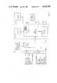
- FIG. 1is a block diagram of the most important component parts of the inventive accident data recorder, also showing the mutual association of the individual structural elements by which the data flow is characterized;
- FIG. 2is a schematic top plan view of the acceleration sensor employed in the present invention.
- FIG. 3is a diagram showing torsional accelerations which may be applied to the acceleration sensor of FIG. 2;
- FIG. 4is a top plan view of the acceleration sensor of the present invention.
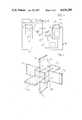
- FIG. 5is a perspective view of an acceleration sensor in accordance with the invention which is responsive to accelerations in any direction of linear displacement or rotation.
- the inventionincludes a central control logic circuit 21 which, in the design of FIG. 1, is supplied with data to be recorded and provides storing of the data in a fixed storage 22 while using an addressing logic 23 which also may be termed a ring addresser, ring storage, or cyclically rotating address counter. and which establishes a new address in respective predetermined time intervals to operate in every instance on a storage area or a storage location in fixed storage 22 and transfer thereto for storage all the data supplied from an interface 24.
- a central control logic circuit 21which, in the design of FIG. 1, is supplied with data to be recorded and provides storing of the data in a fixed storage 22 while using an addressing logic 23 which also may be termed a ring addresser, ring storage, or cyclically rotating address counter. and which establishes a new address in respective predetermined time intervals to operate in every instance on a storage area or a storage location in fixed storage 22 and transfer thereto for storage all the data supplied from an interface 24.
- the addressing logictermed a ring addresser in the following, operates cyclically in a closed loop and, after a predetermined cycle duration or recording time which is variable, readdresses the storage locations which have been addressed at the start of the cycle and released for data storing, so that new data are written over the earlier data. All the data are supplied through interface 24 from a tachogenerator or displacement sensor preferably furnishing a predetermined number of pulses per wheel revolution, for each wheel separately if desired, and thus permitting with reference to the respective time base data to determine the travelled distance or the corresponding speed. This external sensor is indicated at 25 in FIG. 1.
- Reference number 26designates an acceleration sensor of a design such that for measuring the wheel rotation, an entirely independent quantity is introduced which is available in all critical instances and capable of picking up an acceleration to which the vehicle is subjected.
- This b sensoris a capacitive system in which the capacitor surfaces are designed as transverse beams and mounted in a way such that the inertia forces in the respective selected axis act directly perpendicularly to the two axes.
- the construction and function of acceleration sensor 26is discussed in more detail hereinafter.
- a plurality of further desired dataare furnished for processing and storing, of which so called status conditions A and status conditions B are enumerated as typical representatives in the showing of FIG. 1.
- the status A datacomprise, for example, the brake light, blinker left, blinker right, headlight, horn, data on ABS effects (anti-block system).
- the status A dataare to represent all functions of the vehicle which are relevant for traffic behavior and are present in digital form or can be converted thereto, and which must be available in highest resolution.
- the storageare supplied to the storage in short time intervals, such as of 100 ms, through the ring addresser as are advantageously also the other data on the function of the vehicle, while the status B data comprise all those functions important for the operation of the vehicle which need not be supplied with a highest resolution and thus are stored in time intervals of 500 ms, for example.
- the status A and status B blocks 27 and 28may be suitably designed for preparing the data transmitted thereto through interface 24, thus, for example also as converters of physical quantities into electrical output quantities, with most of the status A and status B data being supposed to be simple yes-no conditions, for example, whether or not the horn has been actuated, so that the outputs of the respective logic elements are in either their zero or their one state.
- an ignition block 29supplying to the control logic circuit of the accident data recorder information that the ignition has been connected, and finally, the control logic circuit itself comprises a display or alarm block 30 which is designed to effect a proper indication calling for checking and/or an evaluation as soon as a sequence of stored data becomes stuck or frozen.
- the basic operation of the inventive data recorderis such that a predetermined number of addressable storage locations or storage areas is present in fixed storage 22.
- about as many storage locationsmay be provided in the fixed storage or basic storage, as are necessary to put down three times data for a recording time period of 60 seconds each, with a recording time 60 seconds proving reasonable and also sufficient for an operation.
- Such a period of timecorresponds in urban traffic at 50 km per hour to a traveled distance of 833 meters, in highway traffic at 100 km per hour to a travelled distance of 1667 meters, and on an express highway at assumed 200 km per hour to a traveled distance of 3333 meters, over which distance then an uninterrupted proof may be furnished of all the relevant functions of the vehicle.
- the recordingthus setting down of the data in the fixed storage, is a function of time and is effected, to a predetermined extent, so that, as just mentioned, the recorded travelled distances augment in proportion to the speed.
- a quartz time baseis provided which is independent of the rest of the system and has a minimum power requirement and is equipped with an emergency drive with a buffer battery, since this is the sole part of the circuitry which must not be switched off.
- This time base 21afurnishes both the clock pulses for a separate time counter and the clock rate of the system for the entire control and storage operation, it being within the scope of the invention, of course, that also microprocessors, single purpose counters, or similar equipment is provided to effect the control and ensure the general operation of the system.
- the fixed storage 22is usually designed as an RAM.
- the addressing logic or ring addresser as a counting loopdetermines the limited storage extent of a recording frequency (duration of one minute for example) and defines a starting address up to the end address, provides for the entry of all data relevant to the vehicle at the individual storage locations and upon reaching the end address, jumps back to the starting address, so that in normal travel, the data in the fixed storage are cyclically renewed by new entries through the counting loop.
- This cyclic operation of the counting loopis interrupted only by the occurrence of a trigger event which is computed by the control logic and interpreted as an accident. This may be done, for example, by continually computing the accelerations reported by the accleration sensor 26 with the predetermined maximum values, and inferring an accident from respective detected disparities. The decision when or whether an accident has occurred can be made with a maximum security, with the respective evaluation criteria being as close as possible to the accelerations occurring during regular travel. To define an accident, it is also possible to make use of further data, in addition to only monitoring the accelerations, for example, a strong retardation in the travel direction without a simultaneous actuation of the brake.
- the last datai.e. the data which due to the cyclic process are at that instant stored in the fixed storage, are frozen, or in other words, ring addresser 23 stops further addressing the storage locations belonging to its hitherto existing counting loop. Only the recording still continues for a limited time, such as for half a minute at most, and at least up to the stop of the vehicle.
- ring addresser 23may jump out of this counting loop and define a next counting loop, also for the duration of one minute, with correspondingly addressed further storage locations in fixed storage 22, whereby the storage locations of the first counting loop become frozen and can no longer be destroyed, namely by any means available to the driver, for example.
- an acceleration sensor shown by way of example in FIG. 2is to design always one capacitor plate as a cantilever beam and to arrange it so that acting inertia forces are effective in the respective selected axis perpendicularly to the beam axis, with the capacitor forming a part of an electronic oscillator, otherwise of any circuit design, and being incorporated in the concept of the oscillator in a way such as to be at least co-determinative of the oscillation frequency of the oscillator. Then, the capacitance is obtained as a linear function of the respective varying deflections which depend on the bending forces, and, with a proper design of the oscillator, the capacitance variations become a linear function of the variation of the oscillation frequency.
- a central clamping body 10is provided in which the cantilever beams in the form of flat tongues 11,12,13 are unilaterally fixed and which, preferably, is at the same time electrically connected to the tongues in such a way that the block of the clamping body is at the common zero potential of the circuitry in which the acceleration sensor is incorporated.
- the tonguesare provided in a single plane, mutually offset through 90°, which makes unnecessary to provide a capacitive sensor pointing in the travel direction.
- Three capacitives sensors F1,F2,F3are thereby obtained, each formed by one of tongues 11, 12, 13 and one of opposing stationary counterplates 11', 12', 13' spaced apart by a predetermined distance, so that in rest position, capacitors with predetermined capacitances are obtained.
- the tongueswhich, preferably, have a throughout uniform cross section, may have a width of 1.4 cm, a length of 2 cm, and a thickness of 0.03 cm, and may be made of beryllium bronze, for example, or, to obtain a still lower dependency of temperature, of a material which is generally known under the designation Nivarox. If in such an emodiment the normal mutual spacing of the plates of each of the capacitance sensors F1, F2, F3 is 0.01 cm, with an overlap length of 0.8 cm, the values listed in the following table are obtained, it being assumed that the acting accelerations will range between -20 g and +20 g:
- Oscillation or vibrationdo not produce an effect of the average capacitance either, since even though capacitance variations superimposing on the respective oscillation or vibration frequency may occur, they cannot be done effectively beyond a period of at least 50 ms which is the integration time provided for evaluating the oscillation frequency.
- FIG. 3The diagrammatical showing of FIG. 3 serves the appreciation of torsional accelerations such as certainly may come to act on the acceleration sensor of FIG. 2 in the direction of double arrow A.
- a torsional acceleration in a given directionproduces the effect that in one of the capacitance sensors, namely F1, in the present example, the acting torsional acceleration b D is subtracted from the lengthwise acceleration b L , while in the other capacitance sensor F3, it is added.
- the two sensors F1 and F3furnish data on converted resulting acceleration values of b1 for F1, and b2 for F3.
- the torsional accelerationscan be computed from the following formula:
- the direction of the acting accelerationsmay be stated as to the direction of the acting accelerations: If the result produced by the first formula relating to the torsional acceleration is positive, then the torsional acceleration acted counterclockwise, in the other instance clockwise. From the formula for the lengthwise acceleration, it results that with a positive value, the acceleration was in the travel direction, and with a negative value, it was a braking acceleration opposite to the travel direction.
- the capacitance sensor F2extends in the travel direction; consequently, the capacitance variations measured therewith lead to the observation that, for example, with an acceleration acting to the right, considered in the travel direction, thus downwardly in the drawing plane, the acceleration indicated by the capacitance sensor F2 is positive, in the other instance negative.
- Sensor F2of course is also responsive to torsional accelerations of the vehicle, however, in such a case, together with sensor F1 and F3, in the manner described above, so in instances where no torsional acceleration is indicated by sensors F1 and F3, an acceleration detected by sensor F2 was one to the left or to the right, considered in the travel direction.
- the tongues producing by their inertia the capacitance variations F1, F2 and F3can be manufactured with such high accuracy that an adjustment should be reduced only to the elimination of possible errors in mounting; within the required region, the matter constant E is independent of temperature and resistant to aging.
- the dielectric constantis also independent of temperature since the entire sensor arrangement is preferably accommodated in a housing under vacuum conditions.
- FIG. 4A practical embodiment of an inventive acceleration sensor in a housing is shown in FIG. 4; the block-shaped clamping body 10 supports tongues 11,12 and 13 which are opposed by stationary counterplates 11',12' and 13'.
- the stationary plates forming the counter electrodesmay be supported on guides which are secured through oblong slots 14 to the bottom plate 15 of the housing 16, so as to make them displaceable in the direction of the movable tongues, to adjust the initial capacitance.
- Each of counterplates 11', 12' and 13'is secured in place in insulated position and their connections are led out through low capacitance solid cables 17 to fixed terminal points I, II and III of the plate, with the common terminal point IV being formed the clamping body 10.
- an acceleration sensor responsive to accelerations in any direction of linear displacement or rotation and generally designated 20comprises a central clamping body 21 supporting individual tongues, and a total of six tongues which are arranged about and fixed to the cube-shaped clamping body in by 90° offset positions, and which, along with corresponding counterplates, form capacitance sensors X1, X2, Y1, Y2 and Z1, Z2.
- Each of these capacitance sensorsforms a part of an oscillatory circuit and is therefore capable of detecting any action to which it is exposed and which results from a torsion or a linear acceleration in the positive or negative direction and of converting the capacitance variations and then making them evaluable in the form of a frequency variation.
- the individual values of the acting accelerationscan be determined by forming the corresponding differential values, as demonstrated above in connection with FIG. 2.
- the following schematic tableshows the data sequences to be stored in chronological order, while taking into account that a data to be recorded of each function require unequal resolution times. Taking a minimum resolution time of 100 ms for the acceleration data, the same resolution, or a 500 ms resolution, may be used for the speed data. The status data also may be proportioned to these two categories. Then, the following data sequence are obtained in time intervals of 100 ms:
- the status datacomprise a total of 13 bits, namely 6 bits for status A and 7 bits for status B.
- the inventive accident data recordercomprises two sub-assemblies, namely the basic apparatus which, as a housing, is firmly built into the motor vehicle and provides for fitting, securing, and protection in the vehicle and at the same time, as far as necessary, accommodates structural elements of the status A and status B blocks 27, 28, as well as of the interface 24 and the tachogenerator, and a slide-in module, also termed storage cassette, designated 31 and framed by broken lines in FIG. 1.
- the storage cassette moduleis a compatible part permitting with a standardized slide-in opening in all basic apparatus, a simple change of individual storage cassettes and comprising the storages, thus the fixed storage 22 and the ring addresser 23 as well as the operational section (control logic with the time base) and the acceleration sensor.
- the accommodation of the acceleration sensor also in the storage cassettehas the advantage that with the removal and later evaluation and due to the possible adjustment of the measuring properties, the calibration of the sensor and departures from the standard may properly be included in the evaluation of the data.
- the first data entered into the fixed storage area of the RAMare the time of putting into operation, the serial number of the receiving apparatus, and the vehicle data. At the same time the time counter is set to zero and the timing is released.
- the pulse transmitter of the tachogenerator(travel or wheel revolution sensor 25) delivers pulses in predetermined maximum intervals.
- the start time SZis entered.
- the end of travelis interpreted as stoppage of the vehicle defined by
- the stoppage time in entered with the last datasignals as the actual system time.
- the ring addresserUpon entering the end of travel time, the ring addresser defines the next recorder loop by counting up the addresses. Then, in this secondary loop, zero data are entered in a normal case. This method makes it possible at a following collision to instantaneously close a new recording and prevents the data of the primary loop from being overwritten with zero data.
- This after-travel timeamounts to about three minutes with the vehicle stopped. Consequently, if during this safety or after-travel time no new trigger event occurs, the data within the range of the ring counter will later be overwritten. If a new trigger event occurs during the safety time, the address offset is moved up and a new sequence with the entry of the trigger time is started.
- the trigger timeis the system time relative to which a definite trigger event is defined as an accident which has occurred and the process of associating the primary storage with the basic storage area is released and thus the data in the storage loop are secured.
- This system timemay additionally be entered, as a three byte word, for example, in the sequence following the trigger event and forms within a recording the reference to other storages. In an evaluation of the driver's behavior, this time fixes the starting point for a detailed resolution of the happening. All the fixed points of secondary definition are computed from this point of time, and relations between two corresponding storage systems may be established as soon as corresponding points of correlation within the storage extension are determined.
- the trigger operationmay be schematically outlined as follows:
- the data sequencestarts with the trigger time which is incorporated into the normal data sequences additionally.
- the trigger bitis recorded in address 1, storage locations 2 to 20 contain the last data spanning 60 seconds, as agreed.
- the ring addresser addressesare counted up and the data are thus secured. Let it be assumed as example that at storage location 5 stopping is registered. Instantly, a new cycle of the ring addresser is defined by the range 21 to 41.
- the starting pointis that in a normal case, a vehicle has stopped 30 second at the latest after a trigger event.
- the speed computation and the measured data delivered by the pulse transducersagree in the stoppage; the ring counter addresses are now counted up by a sequence width.
- the secured datacomprise about 40 seconds of pre-trigger data and 20 seconds of past-trigger data.
- a follow-up collision after a collision accident and stoppagemay claim the second storage sequence and thus secure up to 50 seconds of zero data.
- the inventionreliably avoids this through a dynamical determination of the shift constant for the ring storage (ring addresser), by disregarding empty storage locations and taking pre-trigger data only up to the start time. Consequently, as a rule, an urban accident will require less than 60 seconds and a follow-up accident not more than 10 to 20 seconds of recording, so that the available storage volume is best utilized.
- the real timeis the absolute system time recomputed to the synchronizing time mark, and if relative data are required from a plurality of systems, namely if more than one motor vehicle participated in the accident, the relative time error of the different systems may be eliminated by a conversion to the time of the receiving system.
- a residual uncertainty in timemay be due to an inaccuracy in the operation of the time base during the reception time difference of two systems. Since the involved time intervals are relatively short, the residual error is negligible.
- Pulses synchronous with the speedcan be derived from an end stage of the transmission through a step-up gearing for the tachometer. It is advisable to design a pulse generator to the effect that a constant number of pulses is produced for every meter of the wheel circumference, so that the recordings in all the systems are comparable with each other without corrections. If the number of pulses produced within a predetermined interval is stored, then the distance traveled during that interval stands in the storage independently of the type of the vehicle.
- the measurement or evaluation of rotationally synchronous pulsesmay be provided directly on the wheel of the vehicle.
- the facts relevant to the evaluation of an accidentmainly relate to the movements of the vehicle which, in turn, result from accelerations to which the vehicle is subjected.
- the type and design of an acceleration meter for any imaginable accelerationhas been discussed above; thus, in addition to the standard travel speed determination, recording of the lengthwisde acceleration is another means for determining the instantaneous value of the travel speed, by integrating the b-t function within the desired time interval. Both these measuring methods complement each other without a gap, since always when one of them does not longer furnish reliable measured values, the other operates in the optimal region.
- the inventive acceleration sensorpermits even in critical regions a collection of the conventionally determined speed values and steps in as substitute as soon as wheel locking prevents a further speed determination or transverse impacts cannot be picked up because of the ineffectiveness of the wheel movements in this direction.
- An emergency operation with a filled-up storageis possible if the bulk of the data of the respective oldest recorded event is reduced to substantial data. This selection may follow predetermined criteria, such as a reduction to data between the standstill and ten seconds before the trigger event. In such an instance, the required maximum storage area per event would amount to only about 20 seconds or 33%.
- a disconnection of the accident data recorder from the power supplycan be prevented only if the result is that at least one function necessary for the operation of the motor vehicle is stopped. Since simple interruptions may be bridged by the accident data recorder, it is advisable, for example, to let an electronic circuit of the engine continuously interrogate the operating condition of the accident data recorder and stop its function if the recorder fails to respond.
- a conditionmay be understood in which the ignition is on, but the accident data recorder remains powerless at least for one minute. Such a condition may be indicated by an acoustic of optical signal and will be entered and secured in the storage area as outage time.
- microprocessor 21/23Upon substituting the term microprocessor 21/23, for the terms control logic circuit and ring addresser used above in connection with FIG. 1, a ring addresser in its hardware designation becomes an illustration of basic operational sequences in a microprocessor. Under the control of central clock pulses representing timing of the microprocessor system and derived from the quartz time base 21a, such a microprocessor 21/23 with the associated fixed storage 22 operates as described hereinafter, where advantageous embodiments are mentioned at the same time. Microprocessor 21/23 of the accident data recorder operates permanently, thus also with the vehicle stopped or parked. The slightly higher power input, if any, might be corrected by correspondingly designed, for example CMOS base, microprocessors.
- Measurements relating to the speed and accelerations, and to the status values of the vehicleare also made continually, their recording, however, is effected only with the vehicle in motion.
- a standstill of the vehicledoes not even stop the computations of the microprocessor which must be done, for example, by corresponding logic operations on the output of b sensors 26, i.e. the measured linear or torsional accelerations, to detect a trigger event caused by an accident.
- a particularly advantageous feature of the present inventionis that after each stop of the vehicle, a computation is started determining the respective actual stoppage time, thus, a counter is started, for example by the quartz controlled timing pulses of the system.
- the new data recording sequencestarts with the entry of this reached count of the counter, which insofar represents only a single value and defines the starting mark for the now commencing entry of next data, for example in 100 ms intervals, to a closed loop in storage 22.
- the microprocessorcounts or defines storage areas (addressing) defining a storage loop as a cyclically circulating simple counter loop, into which the measured data are entered. (the computed data need not be entered since they can be computed therefrom anytime later again). As soon this (primary) counting loop reaches a predetermined value, it jumps back again to the starting address and the data earlier entered in this storage loop are overwritten.
- such a simple primary counting loopmay receive data for one minute, for example.
- the actual stoppage timesare determined by the above-mentioned counting process, so that due to this operational precaution, the travel data contained in the storage are not overwritten by the following empty data if, for example, stops at traffic lights are concerned. It will be understood that in such an instance, substantially more data may be written, and insofar packed, onto a storage loop receiving travel data for the duration of one minute.
- the interface circuit for the accleration or travel sensorsmay comprise, for example, four buffered counters, i.e. counters having their outputs applied to a bus through a buffer.
- the microprocessorinterrogates these counter counts in accordance with its program, upon having caused itself a counter stop in advance. Immediately after the interrogation, the respective counters for the acceleration and travel sensors are reset and restart their counting. In the meantime, namely at the here assumed 100 ms spacing of the respective data entries, the microprocessor has enough time to compute an accident-caused trigger event by suitably interconnecting the measured data with the interrogated ones. Such a trigger event is given, of course, any time one of the measured acceleration values of itself exceeds a predetermined threshold value.
- the microprocessorof course computes resulting values from the measured lengthwise and transverse accelerations and may detect an accident-caused trigger event even if the individual acceleration values were not excessive.
- the determination of the torsional accelerationis a simple subtraction, as already mentioned above, and an angular acceleration can correspondingly be computed by means of an algorithm.
- the detection of a trigger eventby which basically another function of the microprocessor explained hereinafter is started, the following is to be noted.
- the inventionmakes possible with a high security also to investigate purely personal accidents, since the determined data can be weighted.
- the microprocessormay detect a trigger event by computation if the lengthwise accleration reaches a certain value which may be far below an assumed threshold, but at which the brake has not been actuated. Therefrom, a personal accident may be inferred. Similarly, by corresponding waiting, additional variations in acceleration occurring at a full brake actuation and which can be defined as impacts suffered by the motor vehicle hitting an obstacle with fully actuated brakes, may be evaluated as a trigger event.
- the microprocessoreven though the vehicle does not stop, leaves the primary data entry loop of itself, thus causes stepping up of the starting address of the recorder by a complete offset of the (primary) storage loop, that is, and this goes for any occurrence of a trigger event, either counted back to the last stop of the vehicle, (data volume between two start marks, so that always only the data relevant to the respective accident are secured and the available storage area can be best utilized) or, if the time elapsed since the last stop is longer than than provided for the primary counting loop (one minute), just the freezing of this one-minute storage loop due to the fact that the microprocessor now works with the new starting address increased by the complete offset.
- the new starting addressis defined, maybe the zero frequencies of the accleration transmitters are entered with the offset, and the counting is started to be able, at any rate of time as well immediately be explained, to establish a relation to the absolute time.
- a third possibility of storing accident data up to their evaluation, even without any computation or detecting of a trigger event by the microprocessor,results from the advantageous basic concept of the present invention, namely that upon an accident, if this accident, for example, only relates to persons and/or the collision with a maybe only very small obstacle has so small consequences that the computer cannot detect a trigger event, the entered data do remain stored because, as already mentioned above, at every stop, and such a stop occurs, assumed that the happening is normal, at every accident due to the driver's reaction, the further picked up (measured) data are no longer taken up by the storage but this actual stop time is recorded through the starting of a new counter.
- the storage cassettewhich, in the preferred embodiment, also comprises the time base, the microprocessor depending on the clock rate of the system, and at least the acceleration sensors, is removed for evaluation. During this removal, the counter which has been started for determining the stoppage time continues to run. If the storage cassette is then read in an evaluating station, which is preferable, the computer of the evaluating station stops the time counter, and the absolute time, which of course is available at the evaluating station, and the count of the time counter are added to the readout data.
- both the counter loopis newly defined by the complete offset, as in any trigger event, i.e. the starting address is correspondingly increased so that the accident data recorder now runs in a secondary counting loop, and simultaneously a time count is started which will no longer be stopped and occupies a single storage location in the fixed storage.
- the microprocessor with the fixed storagemay further be so organized that even with a cyclic counting loop, intermediate stops are recorded in the secondary (new) storage loop again by corresponding parallel counting under the same clock rate.
Landscapes
- Physics & Mathematics (AREA)
- General Physics & Mathematics (AREA)
- Time Recorders, Dirve Recorders, Access Control (AREA)
Abstract
Description
______________________________________b A outside A medium C fg mm mm p.sup.F Hz______________________________________-20.0 0.0600 0.0838 11.84 422084-10.0 0.0800 0.0919 10.79 463005-1.0 0.0980 0.0992 10.00 499834-0.5 0.0990 0.0996 9.96 501880-0.2 0.0996 0.0998 9.93 503108-0.1 0.0998 0.0999 9.93 503517+0.0 0.1000 0.1000 9.92 503926+0.1 0.1002 0.1001 9.91 504335+0.2 0.1004 0.1002 9.90 504745+0.5 0.1010 0.1004 9.88 505972+1.0 0.1020 0.1008 9.84 508018+10.0 0.1200 0.1081 9.17 544847+20.0 0.1400 0.1162 8.53 585768______________________________________
b.sub.D =(b2-b1)/2.
b.sub.L =(b2+b1)/2.
______________________________________0 100 200 300 400 500 600 700 ms______________________________________SZ TZ EZvl vl vl vl vl vl vl vlbl bl bl bl bl bl bl blbq bq bq bq bq bq bq bqbw bw bw bw bw bw bw bwS.A. + B S.A. S.A. S.A. + B S.A. S.A. + B S.A. S.A.______________________________________
______________________________________SZ start time TZ trigger timeEZ rest time vl lengthwise speedbl lengthwise acceleration bq transverse accelerationbw torsional acceleration S.A. status AS.B. status B______________________________________
______________________________________T E 1 2 3 4 5 6 7 8 920Ring Addresser Range 1019 18 17 16 15 14 13 12 11______________________________________
Claims (14)
Applications Claiming Priority (4)
| Application Number | Priority Date | Filing Date | Title |
|---|---|---|---|
| DE3306814 | 1983-02-26 | ||
| DE3306814 | 1983-02-26 | ||
| DE19843405757DE3405757A1 (en) | 1983-02-26 | 1984-02-17 | ACCIDENT RECORDER |
| DE3405757 | 1984-02-17 |
Publications (1)
| Publication Number | Publication Date |
|---|---|
| US4638289Atrue US4638289A (en) | 1987-01-20 |
Family
ID=25808564
Family Applications (1)
| Application Number | Title | Priority Date | Filing Date |
|---|---|---|---|
| US06/676,193Expired - LifetimeUS4638289A (en) | 1983-02-26 | 1984-02-24 | Accident data recorder |
Country Status (4)
| Country | Link |
|---|---|
| US (1) | US4638289A (en) |
| EP (1) | EP0118818B1 (en) |
| DE (2) | DE3405757A1 (en) |
| WO (1) | WO1984003359A1 (en) |
Cited By (166)
| Publication number | Priority date | Publication date | Assignee | Title |
|---|---|---|---|---|
| GB2213938A (en)* | 1987-12-17 | 1989-08-23 | Dana Corp | Monitoring the operation of a vehicle drive shaft |
| US4862394A (en)* | 1987-01-28 | 1989-08-29 | Dallas Instruments Incorporated | Drop height recorder |
| US4905507A (en)* | 1988-03-24 | 1990-03-06 | Alfred Teves Gmbh | Multiple-function motion sensor for automotive vehicle slip and attitude control |
| US4987541A (en)* | 1986-12-29 | 1991-01-22 | Szekely Levente | Method for storing run data of a vehicle in the memory of an electronic tachograph and apparatus for carrying out the method |
| US4992943A (en)* | 1989-02-13 | 1991-02-12 | Mccracken Jack J | Apparatus for detecting and storing motor vehicle impact data |
| AT396449B (en)* | 1991-08-12 | 1993-09-27 | Pirc Bogumil Ing | DEVICE FOR MONITORING VEHICLES |
| WO1993021583A1 (en)* | 1992-04-13 | 1993-10-28 | Vehicle Computer Corporation | A system for measuring and recording data for a motor vehicle |
| US5267159A (en)* | 1990-09-13 | 1993-11-30 | Neall Donald L O | Mileage recording and display apparatus |
| WO1993024894A1 (en)* | 1992-06-04 | 1993-12-09 | Mor, Yitzchak | Anti-collision system for vehicles |
| GB2268608A (en)* | 1992-06-10 | 1994-01-12 | Norm Pacific Automat Corp | Vehicle accident prevention and recording system |
| US5338206A (en)* | 1990-03-01 | 1994-08-16 | Technischer Uberwachungsverein Bayern E.V. | Apparatus and method for testing effects of a motor vehicle accident |
| US5353023A (en)* | 1991-06-27 | 1994-10-04 | Mitsubishi Denki Kabushiki Kaisha | Navigation system for cars |
| US5388045A (en)* | 1992-08-27 | 1995-02-07 | Nippondenso Co., Ltd. | Self-diagnostic apparatus of vehicles |
| US5412570A (en)* | 1991-11-11 | 1995-05-02 | Mannesmann Kienzle Gmbh | Apparatus for recording driving data with a temporal resolution adapted to the signal shape of analog measurement signals |
| US5430432A (en)* | 1992-12-14 | 1995-07-04 | Camhi; Elie | Automotive warning and recording system |
| US5446659A (en)* | 1993-04-20 | 1995-08-29 | Awaji Ferryboat Kabushiki Kaisha | Traffic accident data recorder and traffic accident reproduction system |
| US5471193A (en)* | 1993-07-12 | 1995-11-28 | Phillips Plastics Corporation | Tamper-resistant vehicle event recorder |
| US5526269A (en)* | 1990-05-09 | 1996-06-11 | Yazaki Corporation | Digital operation recorder |
| US5548273A (en)* | 1993-06-29 | 1996-08-20 | Competition Components International Pty Ltd | Vehicle driving monitor apparatus |
| US5631627A (en)* | 1995-12-12 | 1997-05-20 | Chou; Yung-Kuei | Control circuit for center high mounted brake lights |
| US5638273A (en)* | 1995-03-29 | 1997-06-10 | Remote Control Systems, Inc. | Vehicle data storage and analysis system and methods |
| US5717391A (en)* | 1997-02-13 | 1998-02-10 | Rodriguez; Otto M. | Traffic event recording method and apparatus |
| US5754965A (en)* | 1994-02-15 | 1998-05-19 | Hagenbuch; Leroy G. | Apparatus for tracking and recording vital signs and task related information of a vehicle to identify operating patterns |
| US5775783A (en)* | 1995-07-28 | 1998-07-07 | Daewoo Electronics Co., Ltd. | Anti-lock braking system capable of recording the operating conditions of elements thereof and recording method therefor |
| WO1998047109A1 (en) | 1997-04-17 | 1998-10-22 | Stage Iii Technologies, L.C. | Vehicle crash data recorder, locator and communicator |
| US5926210A (en)* | 1995-07-28 | 1999-07-20 | Kalatel, Inc. | Mobile, ground-based platform security system which transmits images that were taken prior to the generation of an input signal |
| US6122959A (en)* | 1998-01-14 | 2000-09-26 | Instrumented Sensor Technology, Inc. | Method and apparatus for recording physical variables of transient acceleration events |
| US6163338A (en)* | 1997-12-11 | 2000-12-19 | Johnson; Dan | Apparatus and method for recapture of realtime events |
| US6185490B1 (en) | 1999-03-15 | 2001-02-06 | Thomas W. Ferguson | Vehicle crash data recorder |
| US6211777B1 (en)* | 1998-11-30 | 2001-04-03 | International Business Machines Corporation | System and method for automatic information exchange between vehicles involved in a collision |
| US6298290B1 (en)* | 1999-12-30 | 2001-10-02 | Niles Parts Co., Ltd. | Memory apparatus for vehicle information data |
| US20020055860A1 (en)* | 2000-10-02 | 2002-05-09 | Steven Wahlbin | Computerized method and system of determining right of way in an accident |
| US6389340B1 (en)* | 1998-02-09 | 2002-05-14 | Gary A. Rayner | Vehicle data recorder |
| US6397132B1 (en) | 1999-09-30 | 2002-05-28 | Siemens Automotive Corporation | Electronic thronttle control with accident recordal unit |
| US20020107912A1 (en)* | 2001-02-08 | 2002-08-08 | Lear Corporation | Motor vehicle drive recorder system which records motor vehicle data proximate an event declared by a motor veicle occupant |
| US6498972B1 (en) | 2002-02-13 | 2002-12-24 | Ford Global Technologies, Inc. | Method for operating a pre-crash sensing system in a vehicle having a countermeasure system |
| US6519519B1 (en) | 2002-02-01 | 2003-02-11 | Ford Global Technologies, Inc. | Passive countermeasure methods |
| US6542077B2 (en) | 1993-06-08 | 2003-04-01 | Raymond Anthony Joao | Monitoring apparatus for a vehicle and/or a premises |
| US20030067541A1 (en)* | 1996-03-27 | 2003-04-10 | Joao Raymond Anthony | Monitoring apparatus and method |
| US6549130B1 (en) | 1993-06-08 | 2003-04-15 | Raymond Anthony Joao | Control apparatus and method for vehicles and/or for premises |
| US20030076981A1 (en)* | 2001-10-18 | 2003-04-24 | Smith Gregory Hugh | Method for operating a pre-crash sensing system in a vehicle having a counter-measure system |
| US6587046B2 (en) | 1996-03-27 | 2003-07-01 | Raymond Anthony Joao | Monitoring apparatus and method |
| US20030139864A1 (en)* | 2002-01-24 | 2003-07-24 | Ford Global Technologies, Inc. | Post collision restraints control module |
| US20030168839A1 (en)* | 2002-03-11 | 2003-09-11 | Mitsubishi Denki Kabushiki Kaisha | Airbag system collision history recording method |
| US20030182035A1 (en)* | 2002-03-19 | 2003-09-25 | Ford Global Technologies, Inc. | Real time stamping synchronization system |
| US20030193404A1 (en)* | 1996-03-27 | 2003-10-16 | Joao Raymond Anthony | Control, monitoring and/or security apparatus and method |
| US20030206102A1 (en)* | 2002-05-01 | 2003-11-06 | Joao Raymond Anthony | Control, monitoring and/or security apparatus and method |
| US20040039503A1 (en)* | 2002-08-26 | 2004-02-26 | International Business Machines Corporation | Secure logging of vehicle data |
| US20040049409A1 (en)* | 2002-09-09 | 2004-03-11 | Stefan Wahlbin | Computerized method and system for determining breach of duty in premises liability for an accident |
| US20040054559A1 (en)* | 2002-09-09 | 2004-03-18 | Stefan Wahlbin | Computerized method and system for determining the contribution of defenses to premises liability for an accident |
| US20040054557A1 (en)* | 2002-09-09 | 2004-03-18 | Stefan Wahlbin | Computerized method and system for estimating premises liability for an accident |
| US20040054558A1 (en)* | 2002-09-09 | 2004-03-18 | Stefan Wahlbin | Computerized method and system for determining claimant status in premises liability for an accident |
| US20040054556A1 (en)* | 2002-09-09 | 2004-03-18 | Stephan Wahlbin | Computerized method and system for determining causation in premises liability for an accident |
| US20040066441A1 (en)* | 2002-05-10 | 2004-04-08 | Robert Jones | Identification card printer-assembler for over the counter card issuing |
| US6721659B2 (en) | 2002-02-01 | 2004-04-13 | Ford Global Technologies, Llc | Collision warning and safety countermeasure system |
| US20040088090A1 (en)* | 2002-11-05 | 2004-05-06 | Sung-Don Wee | System for reading vehicle accident information using telematics system |
| US20040102984A1 (en)* | 2002-11-27 | 2004-05-27 | Stefan Wahlbin | Computerized method and system for estimating liability using recorded vehicle data |
| US20040103005A1 (en)* | 2002-11-27 | 2004-05-27 | Stefan Wahlbin | Computerized method and system for estimating monetary damages due to injuries in an accident from liability estimated using a computer system |
| US20040103006A1 (en)* | 2002-11-27 | 2004-05-27 | Stefan Wahlbin | Computerized method and system for estimating an effect on liability using a comparison of the actual speed of vehicles with a specified speed |
| US20040103009A1 (en)* | 2002-11-27 | 2004-05-27 | Stefan Wahlbin | Computerized method and system for creating pre-configured claim reports including liability in an accident estimated using a computer system |
| US20040103007A1 (en)* | 2002-11-27 | 2004-05-27 | Stefan Wahlbin | Computerized method and system for estimating an effect on liability using claim data accessed from claim reporting software |
| US20040102985A1 (en)* | 2002-11-27 | 2004-05-27 | Stefan Wahlbin | Computerized method and system for estimating an effect on liability based on the stopping distance of vehicles |
| US20040103010A1 (en)* | 2002-11-27 | 2004-05-27 | Stephan Wahlbin | Computerized method and system for estimating an effect on liability of the speed of vehicles in an accident and time and distance traveled by the vehicles |
| US20040103008A1 (en)* | 2002-11-27 | 2004-05-27 | Stefan Wahlbin | Computerized method and system for estimating liability for an accident from an investigation of the accident |
| US20040111301A1 (en)* | 2002-11-27 | 2004-06-10 | Stefan Wahlbin | Computerized method and system for estimating liability for an accident using dynamic generation of questions |
| US20040111200A1 (en)* | 2001-11-29 | 2004-06-10 | Rao Manoharprasad K. | Vehicle sensing based pre-crash threat assessment system |
| US20040153362A1 (en)* | 1996-01-29 | 2004-08-05 | Progressive Casualty Insurance Company | Monitoring system for determining and communicating a cost of insurance |
| US6775605B2 (en) | 2001-11-29 | 2004-08-10 | Ford Global Technologies, Llc | Remote sensing based pre-crash threat assessment system |
| US20040177285A1 (en)* | 2001-07-17 | 2004-09-09 | Albrecht Klotz | Method for the temporal synchronisation of a plurality of vehicle sensors |
| US20040189454A1 (en)* | 2003-03-25 | 2004-09-30 | Yasuki Shimoyama | Sensor device for detecting and transmitting vehicle motion data |
| US6816748B1 (en)* | 2000-10-12 | 2004-11-09 | Winbond Electronics Corp. | Smart automatic recording system and method for monitoring wafer fragmentation |
| US6831572B2 (en) | 2002-01-29 | 2004-12-14 | Ford Global Technologies, Llc | Rear collision warning system |
| US6865457B1 (en) | 2000-08-31 | 2005-03-08 | Lisa Mittelsteadt | Automobile monitoring for operation analysis |
| US20050161512A1 (en)* | 2001-12-24 | 2005-07-28 | Jones Robert L. | Optically variable personalized indicia for identification documents |
| US20050171663A1 (en)* | 2000-08-31 | 2005-08-04 | Lisa Mittelsteadt | Automobile monitoring for operation analysis |
| US20060031103A1 (en)* | 2004-08-06 | 2006-02-09 | Henry David S | Systems and methods for diagram data collection |
| US7009500B2 (en) | 2002-02-13 | 2006-03-07 | Ford Global Technologies, Llc | Method for operating a pre-crash sensing system in a vehicle having a countermeasure system using stereo cameras |
| US20060059021A1 (en)* | 2004-09-15 | 2006-03-16 | Jim Yulman | Independent adjuster advisor |
| WO2006052080A1 (en)* | 2004-11-10 | 2006-05-18 | Hong Chol Park | Accident data recording system in vehicle |
| US20070078571A1 (en)* | 2004-11-01 | 2007-04-05 | Heffington Mark F | Programmable automotive computer system having start time and wheel spin correction |
| WO2007017730A3 (en)* | 2005-08-05 | 2007-04-26 | Toyota Motor Co Ltd | Vehicular data recording apparatus |
| US20070152067A1 (en)* | 2001-12-24 | 2007-07-05 | Daoshen Bi | Covert variable information on ID documents and methods of making same |
| US20070187515A1 (en)* | 2001-12-24 | 2007-08-16 | George Theodossiou | Laser Etched Security Features for Identification Documents and Methods of Making Same |
| US20070219685A1 (en)* | 2006-03-16 | 2007-09-20 | James Plante | Vehicle event recorders with integrated web server |
| US20070257815A1 (en)* | 2006-05-08 | 2007-11-08 | Drivecam, Inc. | System and method for taking risk out of driving |
| US20070260361A1 (en)* | 2006-05-08 | 2007-11-08 | Drivecam, Inc. | System and Method for Selective Review of Event Data |
| US20070257804A1 (en)* | 2006-05-08 | 2007-11-08 | Drivecam, Inc. | System and Method for Reducing Driving Risk With Foresight |
| US20070257781A1 (en)* | 2006-05-08 | 2007-11-08 | Drivecam, Inc. | System and Method for Identifying Non-Event Profiles |
| US20070260363A1 (en)* | 2006-05-08 | 2007-11-08 | Drivecam, Inc. | System and Method for Wireless Delivery of Event Data |
| US20070257782A1 (en)* | 2006-05-08 | 2007-11-08 | Drivecam, Inc. | System and Method for Multi-Event Capture |
| US20070268158A1 (en)* | 2006-05-09 | 2007-11-22 | Drivecam, Inc. | System and Method for Reducing Driving Risk With Insight |
| US20080043736A1 (en)* | 2006-08-18 | 2008-02-21 | Drivecam, Inc. | Data Transfer System and Method |
| US20080111666A1 (en)* | 2006-11-09 | 2008-05-15 | Smartdrive Systems Inc. | Vehicle exception event management systems |
| US20080154712A1 (en)* | 2006-12-13 | 2008-06-26 | Crown Equipment Corporation | Fleet management system |
| US7397363B2 (en) | 1993-06-08 | 2008-07-08 | Raymond Anthony Joao | Control and/or monitoring apparatus and method |
| US20080258885A1 (en)* | 2007-04-21 | 2008-10-23 | Synectic Systems Group Limited | System and method for recording environmental data in vehicles |
| US7463952B2 (en) | 2004-10-13 | 2008-12-09 | Continental Automotive France | Method and device for processing measurement signals from a movement sensor on board a motor vehicle |
| US20090024274A1 (en)* | 2006-03-29 | 2009-01-22 | Fujitsu Microelectonics Limited | Recording device and recording method |
| US20090082918A1 (en)* | 2007-09-25 | 2009-03-26 | Hendrix Jr James Edward | Motions Dynamics Recorder |
| US20090106052A1 (en)* | 2007-10-22 | 2009-04-23 | Eytan Moldovan | Computerized acquisition and compilation of vehicle accident information |
| US20090157255A1 (en)* | 2005-12-08 | 2009-06-18 | Smart Drive Systems, Inc. | Vehicle Event Recorder Systems |
| US20090187430A1 (en)* | 2008-01-18 | 2009-07-23 | Frank Scalet | Determining recommended settlement amounts by adjusting values derived from matching similar claims |
| US20090240462A1 (en)* | 2008-03-21 | 2009-09-24 | Analog Devices, Inc. | System and Method for Capturing an Event in MEMS Inertial Sensors |
| US20090248241A1 (en)* | 2008-03-31 | 2009-10-01 | Renesas Technology Corp. | Automotive recorder |
| US20100039247A1 (en)* | 2006-12-13 | 2010-02-18 | Ziegler Ronald L | Impact sensing usable with fleet management system |
| US7765039B1 (en) | 1994-02-15 | 2010-07-27 | Hagenbuch Leroy G | Apparatus for tracking and recording vital signs and task-related information of a vehicle to identify operating patterns |
| US7789311B2 (en) | 2003-04-16 | 2010-09-07 | L-1 Secure Credentialing, Inc. | Three dimensional data storage |
| US20100228588A1 (en)* | 2009-02-11 | 2010-09-09 | Certusview Technologies, Llc | Management system, and associated methods and apparatus, for providing improved visibility, quality control and audit capability for underground facility locate and/or marking operations |
| US20100228428A1 (en)* | 2006-12-13 | 2010-09-09 | Crown Equipment Corporation | Information system for industrial vehicles |
| US20100235056A1 (en)* | 2007-09-03 | 2010-09-16 | Norman Schuetze | Control unit and method for activating occupant protection means |
| US7804982B2 (en) | 2002-11-26 | 2010-09-28 | L-1 Secure Credentialing, Inc. | Systems and methods for managing and detecting fraud in image databases used with identification documents |
| US7809586B2 (en) | 2002-11-27 | 2010-10-05 | Computer Sciences Corporation | Computerized method and system for estimating an effect on liability using a comparison of the actual speed of a vehicle in an accident and time and distance traveled by the vehicles in a merging vehicle accident |
| US20100257292A1 (en)* | 2009-04-03 | 2010-10-07 | Analog Devices, Inc. | Digital Output Sensor FIFO Buffer with Single Port Memory |
| US7815124B2 (en) | 2002-04-09 | 2010-10-19 | L-1 Secure Credentialing, Inc. | Image processing techniques for printing identification cards and documents |
| US7827045B2 (en) | 2003-11-05 | 2010-11-02 | Computer Sciences Corporation | Systems and methods for assessing the potential for fraud in business transactions |
| US20100305812A1 (en)* | 2009-05-26 | 2010-12-02 | Toyota Jidosha Kabushiki Kaisha | Event information collecting system for vehicle and method for collecting event information on vehicle |
| US20110022442A1 (en)* | 2006-12-13 | 2011-01-27 | Crown Equipment Corporation | Information system for industrial vehicles including cyclical recurring vehicle information message |
| US20110040440A1 (en)* | 2009-08-12 | 2011-02-17 | Crown Equipment Corporation | Information system for industrial vehicles |
| US7941258B1 (en) | 2000-08-31 | 2011-05-10 | Strategic Design Federation W, Inc. | Automobile monitoring for operation analysis |
| US8140358B1 (en) | 1996-01-29 | 2012-03-20 | Progressive Casualty Insurance Company | Vehicle monitoring system |
| US20120197481A1 (en)* | 2011-01-27 | 2012-08-02 | Denso Corporation | Vehicular data recording apparatus |
| US8520070B1 (en) | 2008-10-30 | 2013-08-27 | Rosco Inc. | Method and system with multiple camera units installed in protective enclosure |
| US20130300552A1 (en)* | 2012-05-10 | 2013-11-14 | Zen Lee CHANG | Vehicular collision-activated information exchange method and apparatus using wireless communication radios |
| US8825273B2 (en)* | 2010-07-21 | 2014-09-02 | Bayerische Motoren Werke Aktiengesellschaft | Method for monitoring a pedestrian detecting device for a vehicle |
| US8880279B2 (en) | 2005-12-08 | 2014-11-04 | Smartdrive Systems, Inc. | Memory management in event recording systems |
| US8892310B1 (en) | 2014-02-21 | 2014-11-18 | Smartdrive Systems, Inc. | System and method to detect execution of driving maneuvers |
| US20150006023A1 (en)* | 2012-11-16 | 2015-01-01 | Scope Technologies Holdings Ltd | System and method for determination of vheicle accident information |
| DE102013218813A1 (en) | 2013-09-19 | 2015-03-19 | Bayerische Motoren Werke Aktiengesellschaft | Method for detecting a collision of a vehicle with a vehicle-external object and corresponding method |
| US8989959B2 (en) | 2006-11-07 | 2015-03-24 | Smartdrive Systems, Inc. | Vehicle operator performance history recording, scoring and reporting systems |
| US9008995B2 (en) | 2008-03-21 | 2015-04-14 | Analog Devices, Inc. | Activity detection in MEMS accelerometers |
| USD727765S1 (en) | 2013-04-25 | 2015-04-28 | Instrumented Sensor Technology, Inc. | Data recorder |
| US9075136B1 (en) | 1998-03-04 | 2015-07-07 | Gtj Ventures, Llc | Vehicle operator and/or occupant information apparatus and method |
| US20150213316A1 (en)* | 2008-11-17 | 2015-07-30 | Liveclips Llc | Method and system for segmenting and transmitting on-demand live-action video in real-time |
| US9183679B2 (en) | 2007-05-08 | 2015-11-10 | Smartdrive Systems, Inc. | Distributed vehicle event recorder systems having a portable memory data transfer system |
| US9201842B2 (en) | 2006-03-16 | 2015-12-01 | Smartdrive Systems, Inc. | Vehicle event recorder systems and networks having integrated cellular wireless communications systems |
| US20160132257A1 (en)* | 2014-11-06 | 2016-05-12 | Western Digital Technologies, Inc. | Mechanical shock mitigation for data storage |
| US9412211B2 (en) | 2014-03-25 | 2016-08-09 | Toyota Motor Engineering & Manufacturing North America, Inc. | System and method for on-vehicle dynamic accident recreation using accident data recording |
| US9501878B2 (en) | 2013-10-16 | 2016-11-22 | Smartdrive Systems, Inc. | Vehicle event playback apparatus and methods |
| US9554080B2 (en) | 2006-11-07 | 2017-01-24 | Smartdrive Systems, Inc. | Power management systems for automotive video event recorders |
| US9610955B2 (en) | 2013-11-11 | 2017-04-04 | Smartdrive Systems, Inc. | Vehicle fuel consumption monitor and feedback systems |
| US9663127B2 (en) | 2014-10-28 | 2017-05-30 | Smartdrive Systems, Inc. | Rail vehicle event detection and recording system |
| US9728228B2 (en) | 2012-08-10 | 2017-08-08 | Smartdrive Systems, Inc. | Vehicle event playback apparatus and methods |
| US9824064B2 (en) | 2011-12-21 | 2017-11-21 | Scope Technologies Holdings Limited | System and method for use of pattern recognition in assessing or monitoring vehicle status or operator driving behavior |
| US9836716B2 (en) | 2006-05-09 | 2017-12-05 | Lytx, Inc. | System and method for reducing driving risk with hindsight |
| US10032226B1 (en) | 2013-03-08 | 2018-07-24 | Allstate Insurance Company | Automatic exchange of information in response to a collision event |
| US10121204B1 (en) | 2013-03-08 | 2018-11-06 | Allstate Insurance Company | Automated accident detection, fault attribution, and claims processing |
| US10152876B2 (en) | 1996-03-27 | 2018-12-11 | Gtj Ventures, Llc | Control, monitoring, and/or security apparatus and method |
| US10255639B1 (en) | 2013-09-17 | 2019-04-09 | Allstate Insurance Company | Obtaining insurance information in response to optical input |
| US10417713B1 (en)* | 2013-03-08 | 2019-09-17 | Allstate Insurance Company | Determining whether a vehicle is parked for automated accident detection, fault attribution, and claims processing |
| US10546441B2 (en) | 2013-06-04 | 2020-01-28 | Raymond Anthony Joao | Control, monitoring, and/or security, apparatus and method for premises, vehicles, and/or articles |
| US10573152B2 (en) | 2002-05-08 | 2020-02-25 | Resource Consortium Limited, Llc | Method and system for remotely monitoring a user |
| US10572943B1 (en) | 2013-09-10 | 2020-02-25 | Allstate Insurance Company | Maintaining current insurance information at a mobile device |
| US10657598B2 (en) | 2012-12-20 | 2020-05-19 | Scope Technologies Holdings Limited | System and method for use of carbon emissions in characterizing driver performance |
| US10713717B1 (en) | 2015-01-22 | 2020-07-14 | Allstate Insurance Company | Total loss evaluation and handling system and method |
| US10796268B2 (en) | 2001-01-23 | 2020-10-06 | Gtj Ventures, Llc | Apparatus and method for providing shipment information |
| US10930093B2 (en) | 2015-04-01 | 2021-02-23 | Smartdrive Systems, Inc. | Vehicle event recording system and method |
| US10963966B1 (en) | 2013-09-27 | 2021-03-30 | Allstate Insurance Company | Electronic exchange of insurance information |
| CN112802229A (en)* | 2021-01-09 | 2021-05-14 | 徐占奇 | Automobile data recorder based on wireless communication and video recording function control method thereof |
| US11030702B1 (en) | 2012-02-02 | 2021-06-08 | Progressive Casualty Insurance Company | Mobile insurance platform system |
| US11069257B2 (en) | 2014-11-13 | 2021-07-20 | Smartdrive Systems, Inc. | System and method for detecting a vehicle event and generating review criteria |
| US11225404B2 (en) | 2006-12-13 | 2022-01-18 | Crown Equipment Corporation | Information system for industrial vehicles |
| US20230086520A1 (en)* | 2020-02-20 | 2023-03-23 | Isuzu Motors Limited | Event information recording device and event information reference system |
| US11720971B1 (en) | 2017-04-21 | 2023-08-08 | Allstate Insurance Company | Machine learning based accident assessment |
| US20230350820A1 (en)* | 2022-04-28 | 2023-11-02 | Infineon Technologies Ag | Systems and methods for concurrent logging and event capture |
| US20230367006A1 (en)* | 2022-05-16 | 2023-11-16 | DC-001, Inc. | Methods and systems for vehicle-based tracking of nearby events |
| US12380373B2 (en) | 2009-09-01 | 2025-08-05 | Crown Equipment Corporation | Information system for industrial vehicles including cyclical recurring vehicle information message |
Families Citing this family (33)
| Publication number | Priority date | Publication date | Assignee | Title |
|---|---|---|---|---|
| FR2574928B1 (en)* | 1984-12-19 | 1988-08-26 | France Etat Armement | ANALOGUE PARAMETER RECORDER ON STATIC DIGITAL MEMORY |
| US4745564B2 (en) | 1986-02-07 | 2000-07-04 | Us Agriculture | Impact detection apparatus |
| HU193852B (en)* | 1986-03-28 | 1987-12-28 | Magyar Allamvasutak | Railway-service data processing and car informing system |
| EP0240833B1 (en)* | 1986-04-11 | 1991-09-11 | Siemens Aktiengesellschaft | Monitoring apparatus for monitoring the operation mode of transmission devices of the information transmission technique |
| FR2615624A1 (en)* | 1987-05-19 | 1988-11-25 | Curti Jean | Device for monitoring the conditions of movement of a moving object, in particular the driving of a motor vehicle |
| DE3920384A1 (en)* | 1989-06-22 | 1991-01-17 | Preh Elektro Feinmechanik | Detecting excessive stresses in vehicle tyres - detecting and recording speeds and decelerations greater than permitted values |
| DE3920385A1 (en)* | 1989-06-22 | 1991-01-03 | Preh Elektro Feinmechanik | Monitoring vehicle operating parameter, e.g. distance covered - deriving values indirectly in case direct sensor is disables, e.g. in hire car |
| DE4019507A1 (en)* | 1990-06-19 | 1992-01-02 | Mannesmann Kienzle Gmbh | DEVICE FOR DATA COLLECTION IN A MOTOR VEHICLE |
| DE4132981A1 (en)* | 1991-01-23 | 1992-08-06 | Schimmelpfennig Karl Heinz | Reconstructing movement trajectory of road vehicle e.g. after accident - evaluating stored signals from analogue sensors relating to vehicle speed and steering wheel position |
| DE4103599A1 (en)* | 1991-02-07 | 1992-08-13 | Friedrich Fredmueller | Recorder for vehicular time, speed and acceleration data - is clocked by radio time signal ensuring simultaneous discontinuity of independent recordings in event of collision |
| DE4111171C1 (en)* | 1991-04-06 | 1992-05-27 | Mannesmann Kienzle Gmbh, 7730 Villingen-Schwenningen, De | |
| DE4130090C1 (en)* | 1991-05-14 | 1992-09-17 | Mannesmann Kienzle Gmbh, 7730 Villingen-Schwenningen, De | Vehicle motion sensing system - samples outputs of sensors and combines them logically with further signal |
| DE4118500C2 (en)* | 1991-06-03 | 1994-07-21 | Joachim Dipl Ing Griepentrog | Detector preferably as an accident detector |
| DE4130080A1 (en)* | 1991-09-06 | 1993-03-18 | Mannesmann Ag | Continuous monitoring and recording of travel information for buses and commercial vehicles - has tacho disc system supplemented by electronic short cycle memory that stores drive conditions in event of collision or similar event. |
| DE4218397A1 (en)* | 1992-06-04 | 1993-12-09 | Mannesmann Kienzle Gmbh | Short path registration device for motor vehicles |
| CH687352C9 (en)* | 1992-09-07 | 2001-07-13 | Diwag Ag | METHOD AND APPARATUS FOR DETERMINING OPERATION AND / OR DRIVING A VEHICLE OR DATA Consequent GELDBETRAEGE. |
| DE4237365A1 (en)* | 1992-11-05 | 1994-05-11 | Mannesmann Kienzle Gmbh | Method and arrangement for storing measurement data in a registration device |
| DE4303470C1 (en)* | 1993-02-06 | 1994-02-17 | Mannesmann Kienzle Gmbh | Accident data recorder for road vehicle - analyses amplitude and duration of acceleration signals, and is held in active condition with increased sensitivity level for limited period after vehicle engine is switched off |
| EP0627710A1 (en)* | 1993-06-01 | 1994-12-07 | Mannesmann Kienzle GmbH | Device for reporting to a central station of an abnormal collision course of a vehicle |
| FR2712106A1 (en)* | 1993-11-02 | 1995-05-12 | Vallade Patrick | Recording device of the type intended to be placed on an automobile road vehicle |
| DE4435014A1 (en)* | 1994-09-23 | 1996-03-28 | Kolley Klaus | Device for detecting locomotion |
| FR2736456B1 (en)* | 1995-07-03 | 1997-08-08 | Loukakos Nicolas | SYSTEM AND METHOD FOR ACQUIRING, RECORDING, RETURNING AND TRANSMITTING INFORMATION RELATING TO VEHICLES |
| JP3272960B2 (en)* | 1996-08-19 | 2002-04-08 | 株式会社データ・テック | Driving recorder and vehicle operation analyzer |
| DE29614745U1 (en)* | 1996-08-24 | 1996-11-28 | moto - spezial Motorradhandel und -service GmbH, 72532 Gomadingen | Device for measuring and displaying at least the speed and speed of vehicles |
| DE19650236A1 (en)* | 1996-12-04 | 1998-06-10 | Mannesmann Vdo Ag | Procedure for storing accident-related data with an accident data memory |
| DE19707847A1 (en)* | 1997-02-27 | 1998-09-10 | Mannesmann Vdo Ag | Procedure for registration of accident events |
| DE19707856C2 (en)* | 1997-02-27 | 2000-05-18 | Mannesmann Vdo Ag | Procedure for evaluating vehicle dynamics data with regard to an accident event |
| EP0871147A3 (en) | 1997-04-09 | 2001-04-18 | Volkswagen Aktiengesellschaft | Method for storing accident related data of a motor vehicle and accident data memory |
| DE19716508A1 (en)* | 1997-04-19 | 1998-11-05 | Mannesmann Vdo Ag | Procedure and accident data storage for providing a time-based data record for accident reconstruction |
| DE29913812U1 (en)* | 1999-08-06 | 1999-11-18 | Adrian, Peter, 56564 Neuwied | Device for detecting and displaying the acceleration of a vehicle |
| AT507033B1 (en) | 2008-06-05 | 2011-09-15 | Efkon Ag | PROCESS AND SYSTEM FOR SIMULTANEOUS VEHICLE AND DRIVING PROFILE MONITORING |
| DE102010062841A1 (en) | 2010-12-10 | 2012-06-14 | Johann Fayoumi | Traffic situation documentation device installed in motor vehicle e.g. bus, has display unit that is provided for representing the image information stored in storage unit |
| DE102019201681A1 (en)* | 2019-02-08 | 2020-08-13 | Zf Friedrichshafen Ag | Device and method for diagnosing a vehicle control as well as computer program product, storage medium and data carrier signal |
Citations (3)
| Publication number | Priority date | Publication date | Assignee | Title |
|---|---|---|---|---|
| US3226981A (en)* | 1962-10-29 | 1966-01-04 | North American Aviation Inc | Condition responsive signal generator for producing a variable frequency signal |
| US3781824A (en)* | 1972-11-20 | 1973-12-25 | Gen Motors Corp | Solid state crash recorder |
| US4180724A (en)* | 1978-03-31 | 1979-12-25 | E-Systems, Inc. | Solid state digital running time indicator |
Family Cites Families (4)
| Publication number | Priority date | Publication date | Assignee | Title |
|---|---|---|---|---|
| US2917300A (en)* | 1956-12-07 | 1959-12-15 | Univ California | Frequency modulating accelerometer |
| DE2818388A1 (en)* | 1978-04-27 | 1979-11-08 | Moto Meter Ag | ARRANGEMENT FOR RECORDING DRIVING ACCIDENTS IN MOTOR VEHICLES |
| US4250487A (en)* | 1978-10-27 | 1981-02-10 | Arnold Robert D | Vehicle speed recorder |
| FR2511509B1 (en)* | 1980-12-31 | 1986-01-31 | Onera (Off Nat Aerospatiale) | ELECTROSTATIC SUSPENSION TRIAXIAL ACCELEROMETER OF A CRUCIFORM TEST MASS |
- 1984
- 1984-02-17DEDE19843405757patent/DE3405757A1/ennot_activeWithdrawn
- 1984-02-24DEDE8484101972Tpatent/DE3463693D1/ennot_activeExpired
- 1984-02-24EPEP84101972Apatent/EP0118818B1/ennot_activeExpired
- 1984-02-24WOPCT/DE1984/000041patent/WO1984003359A1/enunknown
- 1984-02-24USUS06/676,193patent/US4638289A/ennot_activeExpired - Lifetime
Patent Citations (3)
| Publication number | Priority date | Publication date | Assignee | Title |
|---|---|---|---|---|
| US3226981A (en)* | 1962-10-29 | 1966-01-04 | North American Aviation Inc | Condition responsive signal generator for producing a variable frequency signal |
| US3781824A (en)* | 1972-11-20 | 1973-12-25 | Gen Motors Corp | Solid state crash recorder |
| US4180724A (en)* | 1978-03-31 | 1979-12-25 | E-Systems, Inc. | Solid state digital running time indicator |
Cited By (342)
| Publication number | Priority date | Publication date | Assignee | Title |
|---|---|---|---|---|
| US4987541A (en)* | 1986-12-29 | 1991-01-22 | Szekely Levente | Method for storing run data of a vehicle in the memory of an electronic tachograph and apparatus for carrying out the method |
| AU613891B2 (en)* | 1986-12-29 | 1991-08-15 | Karolyne Otta | Method for storing run data of a vehicule in the memory of anelectronic tachograph and apparatus for carrying out the method |
| US4862394A (en)* | 1987-01-28 | 1989-08-29 | Dallas Instruments Incorporated | Drop height recorder |
| GB2213938B (en)* | 1987-12-17 | 1992-01-02 | Dana Corp | An instrument for monitoring the performance of a vehicle drive shaft |
| GB2213938A (en)* | 1987-12-17 | 1989-08-23 | Dana Corp | Monitoring the operation of a vehicle drive shaft |
| US4905507A (en)* | 1988-03-24 | 1990-03-06 | Alfred Teves Gmbh | Multiple-function motion sensor for automotive vehicle slip and attitude control |
| US4992943A (en)* | 1989-02-13 | 1991-02-12 | Mccracken Jack J | Apparatus for detecting and storing motor vehicle impact data |
| US5338206A (en)* | 1990-03-01 | 1994-08-16 | Technischer Uberwachungsverein Bayern E.V. | Apparatus and method for testing effects of a motor vehicle accident |
| US5526269A (en)* | 1990-05-09 | 1996-06-11 | Yazaki Corporation | Digital operation recorder |
| US5267159A (en)* | 1990-09-13 | 1993-11-30 | Neall Donald L O | Mileage recording and display apparatus |
| US5353023A (en)* | 1991-06-27 | 1994-10-04 | Mitsubishi Denki Kabushiki Kaisha | Navigation system for cars |
| AT396449B (en)* | 1991-08-12 | 1993-09-27 | Pirc Bogumil Ing | DEVICE FOR MONITORING VEHICLES |
| EP0530174B1 (en)* | 1991-08-12 | 1996-03-20 | Bogumil Pirc | Apparatus for monitoring vehicles |
| AU661735B2 (en)* | 1991-11-11 | 1995-08-03 | Vdo Adolf Schindling Aktiengesellschaft | An apparatus for registering driving data of a motor vehicle |
| US5412570A (en)* | 1991-11-11 | 1995-05-02 | Mannesmann Kienzle Gmbh | Apparatus for recording driving data with a temporal resolution adapted to the signal shape of analog measurement signals |
| WO1993021583A1 (en)* | 1992-04-13 | 1993-10-28 | Vehicle Computer Corporation | A system for measuring and recording data for a motor vehicle |
| US5357438A (en)* | 1992-06-04 | 1994-10-18 | Dan Davidian | Anti-collision system for vehicles |
| WO1993024894A1 (en)* | 1992-06-04 | 1993-12-09 | Mor, Yitzchak | Anti-collision system for vehicles |
| GB2268608A (en)* | 1992-06-10 | 1994-01-12 | Norm Pacific Automat Corp | Vehicle accident prevention and recording system |
| US5388045A (en)* | 1992-08-27 | 1995-02-07 | Nippondenso Co., Ltd. | Self-diagnostic apparatus of vehicles |
| US5430432A (en)* | 1992-12-14 | 1995-07-04 | Camhi; Elie | Automotive warning and recording system |
| AU669785B2 (en)* | 1993-04-20 | 1996-06-20 | Awaji Ferryboat Kabushiki Kaisha | Traffic accident data recorder and traffic accident reproduction system |
| US5446659A (en)* | 1993-04-20 | 1995-08-29 | Awaji Ferryboat Kabushiki Kaisha | Traffic accident data recorder and traffic accident reproduction system |
| US6549130B1 (en) | 1993-06-08 | 2003-04-15 | Raymond Anthony Joao | Control apparatus and method for vehicles and/or for premises |
| US6542077B2 (en) | 1993-06-08 | 2003-04-01 | Raymond Anthony Joao | Monitoring apparatus for a vehicle and/or a premises |
| US7397363B2 (en) | 1993-06-08 | 2008-07-08 | Raymond Anthony Joao | Control and/or monitoring apparatus and method |
| US5548273A (en)* | 1993-06-29 | 1996-08-20 | Competition Components International Pty Ltd | Vehicle driving monitor apparatus |
| US5471193A (en)* | 1993-07-12 | 1995-11-28 | Phillips Plastics Corporation | Tamper-resistant vehicle event recorder |
| US8442715B2 (en) | 1994-02-15 | 2013-05-14 | Leroy G. Hagenbuch | Apparatus for tracking and recording vital signs and task-related information of a vehicle to identify operating patterns |
| US5754965A (en)* | 1994-02-15 | 1998-05-19 | Hagenbuch; Leroy G. | Apparatus for tracking and recording vital signs and task related information of a vehicle to identify operating patterns |
| US8532867B1 (en) | 1994-02-15 | 2013-09-10 | Leroy G. Hagenbuch | Apparatus for tracking and recording vital signs and task-related information of a vehicle to identify operating patterns |
| US8457833B2 (en) | 1994-02-15 | 2013-06-04 | Leroy G. Hagenbuch | Apparatus for tracking and recording vital signs and task-related information of a vehicle to identify operating patterns |
| US9177426B2 (en) | 1994-02-15 | 2015-11-03 | Leroy G. Hagenbuch | Apparatus for tracking and recording vital signs and task-related information of a vehicle to identify operating patterns |
| US7765039B1 (en) | 1994-02-15 | 2010-07-27 | Hagenbuch Leroy G | Apparatus for tracking and recording vital signs and task-related information of a vehicle to identify operating patterns |
| US8014917B2 (en) | 1994-02-15 | 2011-09-06 | Hagenbuch Leroy G | Apparatus for tracking and recording vital signs and task-related information of a vehicle to identify operating patterns |
| US20100286865A1 (en)* | 1994-02-15 | 2010-11-11 | Hagenbuch Leroy G | Apparatus for Tracking and Recording Vital Signs and Task-Related Information of a Vehicle to Identify Operating Patterns |
| US20110153154A1 (en)* | 1994-02-15 | 2011-06-23 | Hagenbuch Leroy G | Apparatus for Tracking and Recording Vital Signs and Task-Related Information of a Vehicle to Identify Operating Patterns |
| US5638273A (en)* | 1995-03-29 | 1997-06-10 | Remote Control Systems, Inc. | Vehicle data storage and analysis system and methods |
| US5775783A (en)* | 1995-07-28 | 1998-07-07 | Daewoo Electronics Co., Ltd. | Anti-lock braking system capable of recording the operating conditions of elements thereof and recording method therefor |
| US5926210A (en)* | 1995-07-28 | 1999-07-20 | Kalatel, Inc. | Mobile, ground-based platform security system which transmits images that were taken prior to the generation of an input signal |
| US5631627A (en)* | 1995-12-12 | 1997-05-20 | Chou; Yung-Kuei | Control circuit for center high mounted brake lights |
| US9754424B2 (en) | 1996-01-29 | 2017-09-05 | Progressive Casualty Insurance Company | Vehicle monitoring system |
| US8595034B2 (en) | 1996-01-29 | 2013-11-26 | Progressive Casualty Insurance Company | Monitoring system for determining and communicating a cost of insurance |
| US8311858B2 (en)* | 1996-01-29 | 2012-11-13 | Progressive Casualty Insurance Company | Vehicle monitoring system |
| US8140358B1 (en) | 1996-01-29 | 2012-03-20 | Progressive Casualty Insurance Company | Vehicle monitoring system |
| US20040153362A1 (en)* | 1996-01-29 | 2004-08-05 | Progressive Casualty Insurance Company | Monitoring system for determining and communicating a cost of insurance |
| US20120209634A1 (en)* | 1996-01-29 | 2012-08-16 | Progressive Casualty Insurance Company | Vehicle monitoring system |
| US8090598B2 (en) | 1996-01-29 | 2012-01-03 | Progressive Casualty Insurance Company | Monitoring system for determining and communicating a cost of insurance |
| US8892451B2 (en) | 1996-01-29 | 2014-11-18 | Progressive Casualty Insurance Company | Vehicle monitoring system |
| US6587046B2 (en) | 1996-03-27 | 2003-07-01 | Raymond Anthony Joao | Monitoring apparatus and method |
| US20030067541A1 (en)* | 1996-03-27 | 2003-04-10 | Joao Raymond Anthony | Monitoring apparatus and method |
| US7277010B2 (en) | 1996-03-27 | 2007-10-02 | Raymond Anthony Joao | Monitoring apparatus and method |
| US10011247B2 (en) | 1996-03-27 | 2018-07-03 | Gtj Ventures, Llc | Control, monitoring and/or security apparatus and method |
| US10152876B2 (en) | 1996-03-27 | 2018-12-11 | Gtj Ventures, Llc | Control, monitoring, and/or security apparatus and method |
| US20030193404A1 (en)* | 1996-03-27 | 2003-10-16 | Joao Raymond Anthony | Control, monitoring and/or security apparatus and method |
| WO1998036396A3 (en)* | 1997-02-13 | 1998-12-03 | Otto M Rodriguez | Traffic event recording method and apparatus |
| US5717391A (en)* | 1997-02-13 | 1998-02-10 | Rodriguez; Otto M. | Traffic event recording method and apparatus |
| WO1998047109A1 (en) | 1997-04-17 | 1998-10-22 | Stage Iii Technologies, L.C. | Vehicle crash data recorder, locator and communicator |
| US6163338A (en)* | 1997-12-11 | 2000-12-19 | Johnson; Dan | Apparatus and method for recapture of realtime events |
| US6122959A (en)* | 1998-01-14 | 2000-09-26 | Instrumented Sensor Technology, Inc. | Method and apparatus for recording physical variables of transient acceleration events |
| US6389340B1 (en)* | 1998-02-09 | 2002-05-14 | Gary A. Rayner | Vehicle data recorder |
| US9075136B1 (en) | 1998-03-04 | 2015-07-07 | Gtj Ventures, Llc | Vehicle operator and/or occupant information apparatus and method |
| US6211777B1 (en)* | 1998-11-30 | 2001-04-03 | International Business Machines Corporation | System and method for automatic information exchange between vehicles involved in a collision |
| US6185490B1 (en) | 1999-03-15 | 2001-02-06 | Thomas W. Ferguson | Vehicle crash data recorder |
| US6397132B1 (en) | 1999-09-30 | 2002-05-28 | Siemens Automotive Corporation | Electronic thronttle control with accident recordal unit |
| US6298290B1 (en)* | 1999-12-30 | 2001-10-02 | Niles Parts Co., Ltd. | Memory apparatus for vehicle information data |
| US9256991B2 (en) | 2000-08-31 | 2016-02-09 | Strategic Design Federation W, Inc. | Automobile monitoring for operation analysis |
| US20050171663A1 (en)* | 2000-08-31 | 2005-08-04 | Lisa Mittelsteadt | Automobile monitoring for operation analysis |
| US6865457B1 (en) | 2000-08-31 | 2005-03-08 | Lisa Mittelsteadt | Automobile monitoring for operation analysis |
| US8352118B1 (en) | 2000-08-31 | 2013-01-08 | Strategic Design Federation W., Inc. | Automobile monitoring for operation analysis |
| US10388080B2 (en) | 2000-08-31 | 2019-08-20 | Strategic Design Federation W, Inc. | Automobile monitoring for operation analysis |
| US7941258B1 (en) | 2000-08-31 | 2011-05-10 | Strategic Design Federation W, Inc. | Automobile monitoring for operation analysis |
| US7584033B2 (en) | 2000-08-31 | 2009-09-01 | Strategic Design Federation W. Inc. | Automobile monitoring for operation analysis |
| US20020087363A1 (en)* | 2000-10-02 | 2002-07-04 | Steven Wahlbin | Computerized method and system of liability assessment for an accident using environmental, vehicle, and driver conditions and driver actions |
| US20020059086A1 (en)* | 2000-10-02 | 2002-05-16 | Steven Wahlbin | Computerized method and system of displaying a roadway configuration relating to an accident |
| US7630909B2 (en) | 2000-10-02 | 2009-12-08 | Computer Sciences Corporation | Computerized method and system for adjusting liability estimates in an accident liability assessment program |
| US8069062B2 (en) | 2000-10-02 | 2011-11-29 | Computer Sciences Corporation | Computerized method and system of determining inconsistencies in witness statements relating to an accident |
| US8000985B2 (en) | 2000-10-02 | 2011-08-16 | Computer Sciences Corporation | Computerized method and system of displaying a roadway configuration relating to an accident |
| US20020082873A1 (en)* | 2000-10-02 | 2002-06-27 | Steven Wahlbin | Computerized method and system of determining right of way and liability for an accident |
| US7680680B2 (en) | 2000-10-02 | 2010-03-16 | Computer Sciences Corporation | Computerized method and system of displaying an impact point relating to an accident |
| US20020069092A1 (en)* | 2000-10-02 | 2002-06-06 | Steven Wahlbin | Computerized method and system of assessing and adjusting liability for an accident |
| US20020069091A1 (en)* | 2000-10-02 | 2002-06-06 | Steven Wahlbin | Computerized method and system of liability assessment for an accident |
| US8468035B2 (en) | 2000-10-02 | 2013-06-18 | Computer Sciences Corporation | Computerized method and system for accumulating liability estimates |
| US20020128881A1 (en)* | 2000-10-02 | 2002-09-12 | Steven Wahlbin | Computerized method and system for adjusting liability estimates in an accident liability assessment program |
| US7904318B2 (en) | 2000-10-02 | 2011-03-08 | Computer Sciences Corporation | Computerized method and system of determining right of way and liability for an accident |
| US20020062232A1 (en)* | 2000-10-02 | 2002-05-23 | Steven Wahlbin | Computerized method and system for adjusting liability estimation factors in an accident liability assessment program |
| US20020091504A1 (en)* | 2000-10-02 | 2002-07-11 | Steven Wahlbin | Computerized method and system for accumulating liability estimates |
| US20020059097A1 (en)* | 2000-10-02 | 2002-05-16 | Steven Wahlbin | Computerized method and system of assigning an absolute liability value for an accident |
| US20020062235A1 (en)* | 2000-10-02 | 2002-05-23 | Steven Wahlbin | Computerized method and system for providing claims data to an accident liability assessment program |
| US7742935B2 (en) | 2000-10-02 | 2010-06-22 | Computer Sciences Corporation | Computerized method and system of determining right of way in an accident |
| US7890352B2 (en) | 2000-10-02 | 2011-02-15 | Computer Sciences Corporation | Computerized method and system of liability assessment for an accident |
| US20020059083A1 (en)* | 2000-10-02 | 2002-05-16 | Steven Wahlbin | Computerized method and system of determining inconsistencies in witness statements relating to an accident |
| US7742936B2 (en) | 2000-10-02 | 2010-06-22 | Computer Sciences Corporation | Computerized method and system of assessing liability for an accident using impact groups |
| US7742988B2 (en) | 2000-10-02 | 2010-06-22 | Computer Sciences Corporation | Computerized method and system for adjusting liability estimation factors in an accident liability assessment program |
| US7752061B2 (en) | 2000-10-02 | 2010-07-06 | Computer Sciences Corporation | Computerized method and system of displaying an accident type |
| US7756729B2 (en) | 2000-10-02 | 2010-07-13 | Computer Sciences Corporation | Computerized method and system for providing claims data to an accident liability assessment program |
| US7848938B2 (en) | 2000-10-02 | 2010-12-07 | Computer Sciences Corporation | Computerized method and system of assigning an absolute liability value for an accident |
| US20020059087A1 (en)* | 2000-10-02 | 2002-05-16 | Steven Wahlbin | Computerized method and system of displaying an impact point relating to an accident |
| US20020055860A1 (en)* | 2000-10-02 | 2002-05-09 | Steven Wahlbin | Computerized method and system of determining right of way in an accident |
| US7890353B2 (en) | 2000-10-02 | 2011-02-15 | Computer Sciences Corporation | Computerized method and system of liability assessment for an accident using environmental, vehicle, and driver conditions and driver actions |
| US6816748B1 (en)* | 2000-10-12 | 2004-11-09 | Winbond Electronics Corp. | Smart automatic recording system and method for monitoring wafer fragmentation |
| US10796268B2 (en) | 2001-01-23 | 2020-10-06 | Gtj Ventures, Llc | Apparatus and method for providing shipment information |
| US20020107912A1 (en)* | 2001-02-08 | 2002-08-08 | Lear Corporation | Motor vehicle drive recorder system which records motor vehicle data proximate an event declared by a motor veicle occupant |
| US20040177285A1 (en)* | 2001-07-17 | 2004-09-09 | Albrecht Klotz | Method for the temporal synchronisation of a plurality of vehicle sensors |
| US7254504B2 (en)* | 2001-07-17 | 2007-08-07 | Robert Bosch Gmbh | Method for the temporal synchronisation of a plurality of vehicle sensors |
| US20030076981A1 (en)* | 2001-10-18 | 2003-04-24 | Smith Gregory Hugh | Method for operating a pre-crash sensing system in a vehicle having a counter-measure system |
| US6819991B2 (en) | 2001-11-29 | 2004-11-16 | Ford Global Technologies, Llc | Vehicle sensing based pre-crash threat assessment system |
| US6775605B2 (en) | 2001-11-29 | 2004-08-10 | Ford Global Technologies, Llc | Remote sensing based pre-crash threat assessment system |
| US20040111200A1 (en)* | 2001-11-29 | 2004-06-10 | Rao Manoharprasad K. | Vehicle sensing based pre-crash threat assessment system |
| US8083152B2 (en) | 2001-12-24 | 2011-12-27 | L-1 Secure Credentialing, Inc. | Laser etched security features for identification documents and methods of making same |
| US20050161512A1 (en)* | 2001-12-24 | 2005-07-28 | Jones Robert L. | Optically variable personalized indicia for identification documents |
| US20070187515A1 (en)* | 2001-12-24 | 2007-08-16 | George Theodossiou | Laser Etched Security Features for Identification Documents and Methods of Making Same |
| US7661600B2 (en) | 2001-12-24 | 2010-02-16 | L-1 Identify Solutions | Laser etched security features for identification documents and methods of making same |
| US7694887B2 (en) | 2001-12-24 | 2010-04-13 | L-1 Secure Credentialing, Inc. | Optically variable personalized indicia for identification documents |
| US7798413B2 (en) | 2001-12-24 | 2010-09-21 | L-1 Secure Credentialing, Inc. | Covert variable information on ID documents and methods of making same |
| US20070152067A1 (en)* | 2001-12-24 | 2007-07-05 | Daoshen Bi | Covert variable information on ID documents and methods of making same |
| US7158870B2 (en) | 2002-01-24 | 2007-01-02 | Ford Global Technologies, Llc | Post collision restraints control module |
| US20030139864A1 (en)* | 2002-01-24 | 2003-07-24 | Ford Global Technologies, Inc. | Post collision restraints control module |
| US6831572B2 (en) | 2002-01-29 | 2004-12-14 | Ford Global Technologies, Llc | Rear collision warning system |
| US6721659B2 (en) | 2002-02-01 | 2004-04-13 | Ford Global Technologies, Llc | Collision warning and safety countermeasure system |
| US6519519B1 (en) | 2002-02-01 | 2003-02-11 | Ford Global Technologies, Inc. | Passive countermeasure methods |
| US7009500B2 (en) | 2002-02-13 | 2006-03-07 | Ford Global Technologies, Llc | Method for operating a pre-crash sensing system in a vehicle having a countermeasure system using stereo cameras |
| US6498972B1 (en) | 2002-02-13 | 2002-12-24 | Ford Global Technologies, Inc. | Method for operating a pre-crash sensing system in a vehicle having a countermeasure system |
| US20030168839A1 (en)* | 2002-03-11 | 2003-09-11 | Mitsubishi Denki Kabushiki Kaisha | Airbag system collision history recording method |
| US6915195B2 (en)* | 2002-03-11 | 2005-07-05 | Mitsubishi Denki Kabushiki Kaisha | Airbag system collision history recording method |
| US20030182035A1 (en)* | 2002-03-19 | 2003-09-25 | Ford Global Technologies, Inc. | Real time stamping synchronization system |
| US6882912B2 (en) | 2002-03-19 | 2005-04-19 | Ford Global Technologies, Llc | Real time stamping synchronization system |
| US7815124B2 (en) | 2002-04-09 | 2010-10-19 | L-1 Secure Credentialing, Inc. | Image processing techniques for printing identification cards and documents |
| US20110123132A1 (en)* | 2002-04-09 | 2011-05-26 | Schneck Nelson T | Image Processing Techniques for Printing Identification Cards and Documents |
| US8833663B2 (en) | 2002-04-09 | 2014-09-16 | L-1 Secure Credentialing, Inc. | Image processing techniques for printing identification cards and documents |
| US10562492B2 (en) | 2002-05-01 | 2020-02-18 | Gtj Ventures, Llc | Control, monitoring and/or security apparatus and method |
| US20030206102A1 (en)* | 2002-05-01 | 2003-11-06 | Joao Raymond Anthony | Control, monitoring and/or security apparatus and method |
| US11302168B2 (en) | 2002-05-08 | 2022-04-12 | Resource Consortium Limited | Method and system for remotely monitoring a user |
| US10573152B2 (en) | 2002-05-08 | 2020-02-25 | Resource Consortium Limited, Llc | Method and system for remotely monitoring a user |
| US7824029B2 (en) | 2002-05-10 | 2010-11-02 | L-1 Secure Credentialing, Inc. | Identification card printer-assembler for over the counter card issuing |
| US20040066441A1 (en)* | 2002-05-10 | 2004-04-08 | Robert Jones | Identification card printer-assembler for over the counter card issuing |
| US6795759B2 (en)* | 2002-08-26 | 2004-09-21 | International Business Machines Corporation | Secure logging of vehicle data |
| US20040039503A1 (en)* | 2002-08-26 | 2004-02-26 | International Business Machines Corporation | Secure logging of vehicle data |
| US7702528B2 (en) | 2002-09-09 | 2010-04-20 | Computer Sciences Corporation | Computerized method and system for determining breach of duty in premises liability for an accident |
| US20040054558A1 (en)* | 2002-09-09 | 2004-03-18 | Stefan Wahlbin | Computerized method and system for determining claimant status in premises liability for an accident |
| US20040049409A1 (en)* | 2002-09-09 | 2004-03-11 | Stefan Wahlbin | Computerized method and system for determining breach of duty in premises liability for an accident |
| US20040054556A1 (en)* | 2002-09-09 | 2004-03-18 | Stephan Wahlbin | Computerized method and system for determining causation in premises liability for an accident |
| US20040054557A1 (en)* | 2002-09-09 | 2004-03-18 | Stefan Wahlbin | Computerized method and system for estimating premises liability for an accident |
| US20040054559A1 (en)* | 2002-09-09 | 2004-03-18 | Stefan Wahlbin | Computerized method and system for determining the contribution of defenses to premises liability for an accident |
| US7672860B2 (en) | 2002-09-09 | 2010-03-02 | Computer Sciences Corporation | Computerized method and system for determining the contribution of defenses to premises liability for an accident |
| US20040088090A1 (en)* | 2002-11-05 | 2004-05-06 | Sung-Don Wee | System for reading vehicle accident information using telematics system |
| US7804982B2 (en) | 2002-11-26 | 2010-09-28 | L-1 Secure Credentialing, Inc. | Systems and methods for managing and detecting fraud in image databases used with identification documents |
| US7702529B2 (en) | 2002-11-27 | 2010-04-20 | Computer Sciences Corporation | Computerized method and system for estimating an effect on liability using claim data accessed from claim reporting software |
| US20040103008A1 (en)* | 2002-11-27 | 2004-05-27 | Stefan Wahlbin | Computerized method and system for estimating liability for an accident from an investigation of the accident |
| US7809586B2 (en) | 2002-11-27 | 2010-10-05 | Computer Sciences Corporation | Computerized method and system for estimating an effect on liability using a comparison of the actual speed of a vehicle in an accident and time and distance traveled by the vehicles in a merging vehicle accident |
| US7725334B2 (en) | 2002-11-27 | 2010-05-25 | Computer Sciences Corporation | Computerized method and system for estimating liability for an accident using dynamic generation of questions |
| US20040103005A1 (en)* | 2002-11-27 | 2004-05-27 | Stefan Wahlbin | Computerized method and system for estimating monetary damages due to injuries in an accident from liability estimated using a computer system |
| US7818187B2 (en) | 2002-11-27 | 2010-10-19 | Computer Sciences Corporation | Computerized method and system for estimating liability |
| US20040103009A1 (en)* | 2002-11-27 | 2004-05-27 | Stefan Wahlbin | Computerized method and system for creating pre-configured claim reports including liability in an accident estimated using a computer system |
| US20040103007A1 (en)* | 2002-11-27 | 2004-05-27 | Stefan Wahlbin | Computerized method and system for estimating an effect on liability using claim data accessed from claim reporting software |
| US20040103010A1 (en)* | 2002-11-27 | 2004-05-27 | Stephan Wahlbin | Computerized method and system for estimating an effect on liability of the speed of vehicles in an accident and time and distance traveled by the vehicles |
| US7895063B2 (en) | 2002-11-27 | 2011-02-22 | Computer Sciences Corporation | Computerized method and system for creating pre-configured claim reports including liability in an accident estimated using a computer system |
| US7792690B2 (en) | 2002-11-27 | 2010-09-07 | Computer Sciences Corporation | Computerized method and system for estimating an effect on liability of the speed of vehicles in an accident and time and distance traveled by the vehicles |
| US20040103006A1 (en)* | 2002-11-27 | 2004-05-27 | Stefan Wahlbin | Computerized method and system for estimating an effect on liability using a comparison of the actual speed of vehicles with a specified speed |
| US7660725B2 (en) | 2002-11-27 | 2010-02-09 | Computer Sciences Corporation | Computerized method and system for estimating an effect on liability based on the stopping distance of vehicles |
| US20040102984A1 (en)* | 2002-11-27 | 2004-05-27 | Stefan Wahlbin | Computerized method and system for estimating liability using recorded vehicle data |
| US20040111301A1 (en)* | 2002-11-27 | 2004-06-10 | Stefan Wahlbin | Computerized method and system for estimating liability for an accident using dynamic generation of questions |
| US20040102985A1 (en)* | 2002-11-27 | 2004-05-27 | Stefan Wahlbin | Computerized method and system for estimating an effect on liability based on the stopping distance of vehicles |
| US7805321B2 (en) | 2002-11-27 | 2010-09-28 | Computer Sciences Corporation | Computerized method and system for estimating liability for an accident from an investigation of the accident |
| US20040189454A1 (en)* | 2003-03-25 | 2004-09-30 | Yasuki Shimoyama | Sensor device for detecting and transmitting vehicle motion data |
| US7789311B2 (en) | 2003-04-16 | 2010-09-07 | L-1 Secure Credentialing, Inc. | Three dimensional data storage |
| US7827045B2 (en) | 2003-11-05 | 2010-11-02 | Computer Sciences Corporation | Systems and methods for assessing the potential for fraud in business transactions |
| US20060031103A1 (en)* | 2004-08-06 | 2006-02-09 | Henry David S | Systems and methods for diagram data collection |
| US20060059021A1 (en)* | 2004-09-15 | 2006-03-16 | Jim Yulman | Independent adjuster advisor |
| US7463952B2 (en) | 2004-10-13 | 2008-12-09 | Continental Automotive France | Method and device for processing measurement signals from a movement sensor on board a motor vehicle |
| US20070078571A1 (en)* | 2004-11-01 | 2007-04-05 | Heffington Mark F | Programmable automotive computer system having start time and wheel spin correction |
| US7647138B2 (en)* | 2004-11-01 | 2010-01-12 | Hypertech Inc. | Programmable automotive computer system having start time and wheel spin correction |
| WO2006052080A1 (en)* | 2004-11-10 | 2006-05-18 | Hong Chol Park | Accident data recording system in vehicle |
| WO2007017730A3 (en)* | 2005-08-05 | 2007-04-26 | Toyota Motor Co Ltd | Vehicular data recording apparatus |
| US20080234890A1 (en)* | 2005-08-05 | 2008-09-25 | Toyota Jidosha Kabushiki Kaisha | Vehicular Data Recording Apparatus |
| CN101238375B (en)* | 2005-08-05 | 2012-02-01 | 丰田自动车株式会社 | Vehicle Data Recording Devices |
| EP2096447A2 (en) | 2005-08-05 | 2009-09-02 | Toyota Jidosha Kabusiki Kaisha | Vehicular data recording apparatus |
| US8160771B2 (en)* | 2005-08-05 | 2012-04-17 | Toyota Jidosha Kabushiki Kaisha | Vehicular data recording apparatus |
| US20090157255A1 (en)* | 2005-12-08 | 2009-06-18 | Smart Drive Systems, Inc. | Vehicle Event Recorder Systems |
| US9911253B2 (en) | 2005-12-08 | 2018-03-06 | Smartdrive Systems, Inc. | Memory management in event recording systems |
| US8880279B2 (en) | 2005-12-08 | 2014-11-04 | Smartdrive Systems, Inc. | Memory management in event recording systems |
| US9226004B1 (en) | 2005-12-08 | 2015-12-29 | Smartdrive Systems, Inc. | Memory management in event recording systems |
| US9633318B2 (en) | 2005-12-08 | 2017-04-25 | Smartdrive Systems, Inc. | Vehicle event recorder systems |
| US10878646B2 (en) | 2005-12-08 | 2020-12-29 | Smartdrive Systems, Inc. | Vehicle event recorder systems |
| US9566910B2 (en) | 2006-03-16 | 2017-02-14 | Smartdrive Systems, Inc. | Vehicle event recorder systems and networks having integrated cellular wireless communications systems |
| US9691195B2 (en) | 2006-03-16 | 2017-06-27 | Smartdrive Systems, Inc. | Vehicle event recorder systems and networks having integrated cellular wireless communications systems |
| US9472029B2 (en) | 2006-03-16 | 2016-10-18 | Smartdrive Systems, Inc. | Vehicle event recorder systems and networks having integrated cellular wireless communications systems |
| US9402060B2 (en) | 2006-03-16 | 2016-07-26 | Smartdrive Systems, Inc. | Vehicle event recorders with integrated web server |
| US10404951B2 (en) | 2006-03-16 | 2019-09-03 | Smartdrive Systems, Inc. | Vehicle event recorders with integrated web server |
| US20070219685A1 (en)* | 2006-03-16 | 2007-09-20 | James Plante | Vehicle event recorders with integrated web server |
| US9208129B2 (en) | 2006-03-16 | 2015-12-08 | Smartdrive Systems, Inc. | Vehicle event recorder systems and networks having integrated cellular wireless communications systems |
| US8996240B2 (en) | 2006-03-16 | 2015-03-31 | Smartdrive Systems, Inc. | Vehicle event recorders with integrated web server |
| US9201842B2 (en) | 2006-03-16 | 2015-12-01 | Smartdrive Systems, Inc. | Vehicle event recorder systems and networks having integrated cellular wireless communications systems |
| US9942526B2 (en) | 2006-03-16 | 2018-04-10 | Smartdrive Systems, Inc. | Vehicle event recorders with integrated web server |
| US9545881B2 (en) | 2006-03-16 | 2017-01-17 | Smartdrive Systems, Inc. | Vehicle event recorder systems and networks having integrated cellular wireless communications systems |
| US20090024274A1 (en)* | 2006-03-29 | 2009-01-22 | Fujitsu Microelectonics Limited | Recording device and recording method |
| US7659827B2 (en) | 2006-05-08 | 2010-02-09 | Drivecam, Inc. | System and method for taking risk out of driving |
| US20070257804A1 (en)* | 2006-05-08 | 2007-11-08 | Drivecam, Inc. | System and Method for Reducing Driving Risk With Foresight |
| US20070257782A1 (en)* | 2006-05-08 | 2007-11-08 | Drivecam, Inc. | System and Method for Multi-Event Capture |
| US20070260363A1 (en)* | 2006-05-08 | 2007-11-08 | Drivecam, Inc. | System and Method for Wireless Delivery of Event Data |
| US7536457B2 (en) | 2006-05-08 | 2009-05-19 | Drivecam, Inc. | System and method for wireless delivery of event data |
| US20070257781A1 (en)* | 2006-05-08 | 2007-11-08 | Drivecam, Inc. | System and Method for Identifying Non-Event Profiles |
| US8314708B2 (en) | 2006-05-08 | 2012-11-20 | Drivecam, Inc. | System and method for reducing driving risk with foresight |
| US20070257815A1 (en)* | 2006-05-08 | 2007-11-08 | Drivecam, Inc. | System and method for taking risk out of driving |
| US8373567B2 (en) | 2006-05-08 | 2013-02-12 | Drivecam, Inc. | System and method for identifying non-event profiles |
| US7804426B2 (en) | 2006-05-08 | 2010-09-28 | Drivecam, Inc. | System and method for selective review of event data |
| US20070260361A1 (en)* | 2006-05-08 | 2007-11-08 | Drivecam, Inc. | System and Method for Selective Review of Event Data |
| US20070268158A1 (en)* | 2006-05-09 | 2007-11-22 | Drivecam, Inc. | System and Method for Reducing Driving Risk With Insight |
| US10235655B2 (en) | 2006-05-09 | 2019-03-19 | Lytx, Inc. | System and method for reducing driving risk with hindsight |
| US9836716B2 (en) | 2006-05-09 | 2017-12-05 | Lytx, Inc. | System and method for reducing driving risk with hindsight |
| US20080043736A1 (en)* | 2006-08-18 | 2008-02-21 | Drivecam, Inc. | Data Transfer System and Method |
| US9554080B2 (en) | 2006-11-07 | 2017-01-24 | Smartdrive Systems, Inc. | Power management systems for automotive video event recorders |
| US10053032B2 (en) | 2006-11-07 | 2018-08-21 | Smartdrive Systems, Inc. | Power management systems for automotive video event recorders |
| US8989959B2 (en) | 2006-11-07 | 2015-03-24 | Smartdrive Systems, Inc. | Vehicle operator performance history recording, scoring and reporting systems |
| US10339732B2 (en) | 2006-11-07 | 2019-07-02 | Smartdrive Systems, Inc. | Vehicle operator performance history recording, scoring and reporting systems |
| US9761067B2 (en) | 2006-11-07 | 2017-09-12 | Smartdrive Systems, Inc. | Vehicle operator performance history recording, scoring and reporting systems |
| US10682969B2 (en) | 2006-11-07 | 2020-06-16 | Smartdrive Systems, Inc. | Power management systems for automotive video event recorders |
| US10471828B2 (en) | 2006-11-09 | 2019-11-12 | Smartdrive Systems, Inc. | Vehicle exception event management systems |
| US11623517B2 (en) | 2006-11-09 | 2023-04-11 | SmartDriven Systems, Inc. | Vehicle exception event management systems |
| US8868288B2 (en) | 2006-11-09 | 2014-10-21 | Smartdrive Systems, Inc. | Vehicle exception event management systems |
| US9738156B2 (en) | 2006-11-09 | 2017-08-22 | Smartdrive Systems, Inc. | Vehicle exception event management systems |
| US20080111666A1 (en)* | 2006-11-09 | 2008-05-15 | Smartdrive Systems Inc. | Vehicle exception event management systems |
| US10013815B2 (en) | 2006-12-13 | 2018-07-03 | Crown Equipment Corporation | Information system for industrial vehicles |
| US10600256B2 (en) | 2006-12-13 | 2020-03-24 | Crown Equipment Corporation | Impact sensing usable with fleet management system |
| US9984341B2 (en) | 2006-12-13 | 2018-05-29 | Crown Equipment Corporation | Information system for industrial vehicles including cyclical recurring vehicle information message |
| US8249910B2 (en) | 2006-12-13 | 2012-08-21 | Crown Equipment Corporation | Fleet management system |
| US20100039247A1 (en)* | 2006-12-13 | 2010-02-18 | Ziegler Ronald L | Impact sensing usable with fleet management system |
| US20080154691A1 (en)* | 2006-12-13 | 2008-06-26 | Wellman Timothy A | Fleet management system |
| US20100228428A1 (en)* | 2006-12-13 | 2010-09-09 | Crown Equipment Corporation | Information system for industrial vehicles |
| US11823502B2 (en) | 2006-12-13 | 2023-11-21 | Crown Equipment Corporation | Impact sensing usable with fleet management system |
| US10599160B2 (en) | 2006-12-13 | 2020-03-24 | Crown Equipment Corporation | Fleet management system |
| US8060400B2 (en) | 2006-12-13 | 2011-11-15 | Crown Equipment Corporation | Fleet management system |
| US11225404B2 (en) | 2006-12-13 | 2022-01-18 | Crown Equipment Corporation | Information system for industrial vehicles |
| US20080154712A1 (en)* | 2006-12-13 | 2008-06-26 | Crown Equipment Corporation | Fleet management system |
| US11947361B2 (en) | 2006-12-13 | 2024-04-02 | Crown Equipment Corporation | Fleet management system |
| US10810521B2 (en) | 2006-12-13 | 2020-10-20 | Crown Equipment Corporation | Information system for industrial vehicles including cyclical recurring vehicle information message |
| US12210353B2 (en) | 2006-12-13 | 2025-01-28 | Crown Equipment Corporation | Fleet management system |
| US20110022442A1 (en)* | 2006-12-13 | 2011-01-27 | Crown Equipment Corporation | Information system for industrial vehicles including cyclical recurring vehicle information message |
| US20080258885A1 (en)* | 2007-04-21 | 2008-10-23 | Synectic Systems Group Limited | System and method for recording environmental data in vehicles |
| US9183679B2 (en) | 2007-05-08 | 2015-11-10 | Smartdrive Systems, Inc. | Distributed vehicle event recorder systems having a portable memory data transfer system |
| US9679424B2 (en) | 2007-05-08 | 2017-06-13 | Smartdrive Systems, Inc. | Distributed vehicle event recorder systems having a portable memory data transfer system |
| US9174596B2 (en)* | 2007-09-03 | 2015-11-03 | Robert Bosch Gmbh | Control unit and method for activating occupant protection means |
| US20100235056A1 (en)* | 2007-09-03 | 2010-09-16 | Norman Schuetze | Control unit and method for activating occupant protection means |
| US20090082918A1 (en)* | 2007-09-25 | 2009-03-26 | Hendrix Jr James Edward | Motions Dynamics Recorder |
| US20090106052A1 (en)* | 2007-10-22 | 2009-04-23 | Eytan Moldovan | Computerized acquisition and compilation of vehicle accident information |
| US20090187430A1 (en)* | 2008-01-18 | 2009-07-23 | Frank Scalet | Determining recommended settlement amounts by adjusting values derived from matching similar claims |
| US8244558B2 (en) | 2008-01-18 | 2012-08-14 | Computer Sciences Corporation | Determining recommended settlement amounts by adjusting values derived from matching similar claims |
| US7991630B2 (en) | 2008-01-18 | 2011-08-02 | Computer Sciences Corporation | Displaying likelihood values for use in settlement |
| US20090187429A1 (en)* | 2008-01-18 | 2009-07-23 | Frank Scalet | Determining amounts for claims settlement using likelihood values |
| US8219424B2 (en) | 2008-01-18 | 2012-07-10 | Computer Sciences Corporation | Determining amounts for claims settlement using likelihood values |
| US20090187431A1 (en)* | 2008-01-18 | 2009-07-23 | Frank Scalet | Adjusting general damages values using equalization values |
| US20090187428A1 (en)* | 2008-01-18 | 2009-07-23 | Frank Scalet | Evaluating effectiveness of claims evaluation, assessment, and settlement processes |
| US20090187432A1 (en)* | 2008-01-18 | 2009-07-23 | Frank Scalet | Displaying likelihood values for use in settlement |
| US20090240462A1 (en)* | 2008-03-21 | 2009-09-24 | Analog Devices, Inc. | System and Method for Capturing an Event in MEMS Inertial Sensors |
| US9008995B2 (en) | 2008-03-21 | 2015-04-14 | Analog Devices, Inc. | Activity detection in MEMS accelerometers |
| US20090248241A1 (en)* | 2008-03-31 | 2009-10-01 | Renesas Technology Corp. | Automotive recorder |
| US9172903B1 (en) | 2008-10-30 | 2015-10-27 | Rosco, Inc. | Method and system with multiple camera units installed in protective enclosure |
| US8520070B1 (en) | 2008-10-30 | 2013-08-27 | Rosco Inc. | Method and system with multiple camera units installed in protective enclosure |
| US10666893B1 (en) | 2008-10-30 | 2020-05-26 | Rosco, Inc. | Method and system with multiple camera units installed in protective enclosure |
| US9635319B1 (en) | 2008-10-30 | 2017-04-25 | Rosco, Inc. | Method and system with multiple camera units installed in protective enclosure |
| US10091453B1 (en) | 2008-10-30 | 2018-10-02 | Rosco, Inc. | Method and system with multiple camera units installed in protective enclosure |
| US11778136B1 (en) | 2008-10-30 | 2023-10-03 | Rosco, Inc. | Method and system with multiple camera units installed in protective enclosure |
| US12069401B1 (en) | 2008-10-30 | 2024-08-20 | Rosco, Inc. | Method and system with multiple camera units installed in protective enclosure |
| US10565453B2 (en)* | 2008-11-17 | 2020-02-18 | Liveclips Llc | Method and system for segmenting and transmitting on-demand live-action video in real-time |
| US20150213316A1 (en)* | 2008-11-17 | 2015-07-30 | Liveclips Llc | Method and system for segmenting and transmitting on-demand live-action video in real-time |
| US20180357483A1 (en)* | 2008-11-17 | 2018-12-13 | Liveclips Llc | Method and system for segmenting and transmitting on-demand live-action video in real-time |
| US10102430B2 (en)* | 2008-11-17 | 2018-10-16 | Liveclips Llc | Method and system for segmenting and transmitting on-demand live-action video in real-time |
| US20210264157A1 (en)* | 2008-11-17 | 2021-08-26 | Liveclips Llc | Method and system for segmenting and transmitting on-demand live-action video in real-time |
| US11625917B2 (en)* | 2008-11-17 | 2023-04-11 | Liveclips Llc | Method and system for segmenting and transmitting on-demand live-action video in real-time |
| US11036992B2 (en)* | 2008-11-17 | 2021-06-15 | Liveclips Llc | Method and system for segmenting and transmitting on-demand live-action video in real-time |
| US8626571B2 (en) | 2009-02-11 | 2014-01-07 | Certusview Technologies, Llc | Management system, and associated methods and apparatus, for dispatching tickets, receiving field information, and performing a quality assessment for underground facility locate and/or marking operations |
| US20100318401A1 (en)* | 2009-02-11 | 2010-12-16 | Certusview Technologies, Llc | Methods and apparatus for performing locate and/or marking operations with improved visibility, quality control and audit capability |
| US20100228588A1 (en)* | 2009-02-11 | 2010-09-09 | Certusview Technologies, Llc | Management system, and associated methods and apparatus, for providing improved visibility, quality control and audit capability for underground facility locate and/or marking operations |
| US9185176B2 (en) | 2009-02-11 | 2015-11-10 | Certusview Technologies, Llc | Methods and apparatus for managing locate and/or marking operations |
| US8731999B2 (en) | 2009-02-11 | 2014-05-20 | Certusview Technologies, Llc | Management system, and associated methods and apparatus, for providing improved visibility, quality control and audit capability for underground facility locate and/or marking operations |
| US20100257292A1 (en)* | 2009-04-03 | 2010-10-07 | Analog Devices, Inc. | Digital Output Sensor FIFO Buffer with Single Port Memory |
| US8156264B2 (en) | 2009-04-03 | 2012-04-10 | Analog Devices, Inc. | Digital output sensor FIFO buffer with single port memory |
| US20100305812A1 (en)* | 2009-05-26 | 2010-12-02 | Toyota Jidosha Kabushiki Kaisha | Event information collecting system for vehicle and method for collecting event information on vehicle |
| US9202320B2 (en)* | 2009-05-26 | 2015-12-01 | Toyota Jidosha Kabushiki Kaisha | Event information collecting system for vehicle and method for collecting event information on vehicle |
| US20110040440A1 (en)* | 2009-08-12 | 2011-02-17 | Crown Equipment Corporation | Information system for industrial vehicles |
| US8725345B2 (en) | 2009-08-12 | 2014-05-13 | Crown Equipment Corporation | Information system for industrial vehicles |
| US8583314B2 (en) | 2009-08-12 | 2013-11-12 | Crown Equipment Corporation | Information system for industrial vehicles |
| US12380373B2 (en) | 2009-09-01 | 2025-08-05 | Crown Equipment Corporation | Information system for industrial vehicles including cyclical recurring vehicle information message |
| US8825273B2 (en)* | 2010-07-21 | 2014-09-02 | Bayerische Motoren Werke Aktiengesellschaft | Method for monitoring a pedestrian detecting device for a vehicle |
| US8565961B2 (en)* | 2011-01-27 | 2013-10-22 | Denso Corporation | Vehicular data recording apparatus |
| US20120197481A1 (en)* | 2011-01-27 | 2012-08-02 | Denso Corporation | Vehicular data recording apparatus |
| US9824064B2 (en) | 2011-12-21 | 2017-11-21 | Scope Technologies Holdings Limited | System and method for use of pattern recognition in assessing or monitoring vehicle status or operator driving behavior |
| US11030702B1 (en) | 2012-02-02 | 2021-06-08 | Progressive Casualty Insurance Company | Mobile insurance platform system |
| US9102261B2 (en)* | 2012-05-10 | 2015-08-11 | Zen Lee CHANG | Vehicular collision-activated information exchange method and apparatus using wireless communication radios |
| US20130300552A1 (en)* | 2012-05-10 | 2013-11-14 | Zen Lee CHANG | Vehicular collision-activated information exchange method and apparatus using wireless communication radios |
| US9728228B2 (en) | 2012-08-10 | 2017-08-08 | Smartdrive Systems, Inc. | Vehicle event playback apparatus and methods |
| US20150006023A1 (en)* | 2012-11-16 | 2015-01-01 | Scope Technologies Holdings Ltd | System and method for determination of vheicle accident information |
| US11157973B2 (en) | 2012-11-16 | 2021-10-26 | Scope Technologies Holdings Limited | System and method for estimation of vehicle accident damage and repair |
| US10657598B2 (en) | 2012-12-20 | 2020-05-19 | Scope Technologies Holdings Limited | System and method for use of carbon emissions in characterizing driver performance |
| US11669911B1 (en) | 2013-03-08 | 2023-06-06 | Allstate Insurance Company | Automated accident detection, fault attribution, and claims processing |
| US10417713B1 (en)* | 2013-03-08 | 2019-09-17 | Allstate Insurance Company | Determining whether a vehicle is parked for automated accident detection, fault attribution, and claims processing |
| US10699350B1 (en) | 2013-03-08 | 2020-06-30 | Allstate Insurance Company | Automatic exchange of information in response to a collision event |
| US10121204B1 (en) | 2013-03-08 | 2018-11-06 | Allstate Insurance Company | Automated accident detection, fault attribution, and claims processing |
| US11158002B1 (en) | 2013-03-08 | 2021-10-26 | Allstate Insurance Company | Automated accident detection, fault attribution and claims processing |
| US11989785B1 (en) | 2013-03-08 | 2024-05-21 | Allstate Insurance Company | Automatic exchange of information in response to a collision event |
| US10032226B1 (en) | 2013-03-08 | 2018-07-24 | Allstate Insurance Company | Automatic exchange of information in response to a collision event |
| USD727765S1 (en) | 2013-04-25 | 2015-04-28 | Instrumented Sensor Technology, Inc. | Data recorder |
| US10546441B2 (en) | 2013-06-04 | 2020-01-28 | Raymond Anthony Joao | Control, monitoring, and/or security, apparatus and method for premises, vehicles, and/or articles |
| US10572943B1 (en) | 2013-09-10 | 2020-02-25 | Allstate Insurance Company | Maintaining current insurance information at a mobile device |
| US11861721B1 (en) | 2013-09-10 | 2024-01-02 | Allstate Insurance Company | Maintaining current insurance information at a mobile device |
| US10255639B1 (en) | 2013-09-17 | 2019-04-09 | Allstate Insurance Company | Obtaining insurance information in response to optical input |
| US11783430B1 (en) | 2013-09-17 | 2023-10-10 | Allstate Insurance Company | Automatic claim generation |
| DE102013218813B4 (en) | 2013-09-19 | 2024-02-22 | Bayerische Motoren Werke Aktiengesellschaft | Method for detecting a collision of a vehicle with an object external to the vehicle and corresponding system |
| DE102013218813A1 (en) | 2013-09-19 | 2015-03-19 | Bayerische Motoren Werke Aktiengesellschaft | Method for detecting a collision of a vehicle with a vehicle-external object and corresponding method |
| US12033217B2 (en) | 2013-09-27 | 2024-07-09 | Allstate Insurance Company | Electronic exchange of insurance information |
| US10963966B1 (en) | 2013-09-27 | 2021-03-30 | Allstate Insurance Company | Electronic exchange of insurance information |
| US10019858B2 (en) | 2013-10-16 | 2018-07-10 | Smartdrive Systems, Inc. | Vehicle event playback apparatus and methods |
| US10818112B2 (en) | 2013-10-16 | 2020-10-27 | Smartdrive Systems, Inc. | Vehicle event playback apparatus and methods |
| US9501878B2 (en) | 2013-10-16 | 2016-11-22 | Smartdrive Systems, Inc. | Vehicle event playback apparatus and methods |
| US11884255B2 (en) | 2013-11-11 | 2024-01-30 | Smartdrive Systems, Inc. | Vehicle fuel consumption monitor and feedback systems |
| US9610955B2 (en) | 2013-11-11 | 2017-04-04 | Smartdrive Systems, Inc. | Vehicle fuel consumption monitor and feedback systems |
| US11260878B2 (en) | 2013-11-11 | 2022-03-01 | Smartdrive Systems, Inc. | Vehicle fuel consumption monitor and feedback systems |
| US9953470B1 (en) | 2014-02-21 | 2018-04-24 | Smartdrive Systems, Inc. | System and method to detect execution of driving maneuvers |
| US8892310B1 (en) | 2014-02-21 | 2014-11-18 | Smartdrive Systems, Inc. | System and method to detect execution of driving maneuvers |
| US11250649B2 (en) | 2014-02-21 | 2022-02-15 | Smartdrive Systems, Inc. | System and method to detect execution of driving maneuvers |
| US9594371B1 (en) | 2014-02-21 | 2017-03-14 | Smartdrive Systems, Inc. | System and method to detect execution of driving maneuvers |
| US10249105B2 (en) | 2014-02-21 | 2019-04-02 | Smartdrive Systems, Inc. | System and method to detect execution of driving maneuvers |
| US11734964B2 (en) | 2014-02-21 | 2023-08-22 | Smartdrive Systems, Inc. | System and method to detect execution of driving maneuvers |
| US10497187B2 (en) | 2014-02-21 | 2019-12-03 | Smartdrive Systems, Inc. | System and method to detect execution of driving maneuvers |
| US9412211B2 (en) | 2014-03-25 | 2016-08-09 | Toyota Motor Engineering & Manufacturing North America, Inc. | System and method for on-vehicle dynamic accident recreation using accident data recording |
| US9663127B2 (en) | 2014-10-28 | 2017-05-30 | Smartdrive Systems, Inc. | Rail vehicle event detection and recording system |
| US20160132257A1 (en)* | 2014-11-06 | 2016-05-12 | Western Digital Technologies, Inc. | Mechanical shock mitigation for data storage |
| US9823859B2 (en)* | 2014-11-06 | 2017-11-21 | Western Digital Technologies, Inc. | Mechanical shock mitigation for data storage |
| US11069257B2 (en) | 2014-11-13 | 2021-07-20 | Smartdrive Systems, Inc. | System and method for detecting a vehicle event and generating review criteria |
| US11348175B1 (en) | 2015-01-22 | 2022-05-31 | Allstate Insurance Company | Total loss evaluation and handling system and method |
| US11682077B2 (en) | 2015-01-22 | 2023-06-20 | Allstate Insurance Company | Total loss evaluation and handling system and method |
| US11017472B1 (en) | 2015-01-22 | 2021-05-25 | Allstate Insurance Company | Total loss evaluation and handling system and method |
| US10713717B1 (en) | 2015-01-22 | 2020-07-14 | Allstate Insurance Company | Total loss evaluation and handling system and method |
| US10930093B2 (en) | 2015-04-01 | 2021-02-23 | Smartdrive Systems, Inc. | Vehicle event recording system and method |
| US11720971B1 (en) | 2017-04-21 | 2023-08-08 | Allstate Insurance Company | Machine learning based accident assessment |
| US20230086520A1 (en)* | 2020-02-20 | 2023-03-23 | Isuzu Motors Limited | Event information recording device and event information reference system |
| US12307837B2 (en)* | 2020-02-20 | 2025-05-20 | Isuzu Motors Limited | Event information recording device and event information reference system |
| CN112802229A (en)* | 2021-01-09 | 2021-05-14 | 徐占奇 | Automobile data recorder based on wireless communication and video recording function control method thereof |
| US20230350820A1 (en)* | 2022-04-28 | 2023-11-02 | Infineon Technologies Ag | Systems and methods for concurrent logging and event capture |
| US12072818B2 (en)* | 2022-04-28 | 2024-08-27 | Infineon Technologies Ag | Systems and methods for concurrent logging and event capture |
| US20230367006A1 (en)* | 2022-05-16 | 2023-11-16 | DC-001, Inc. | Methods and systems for vehicle-based tracking of nearby events |
| US12416722B2 (en)* | 2022-05-16 | 2025-09-16 | Spartan Radar, Inc. | Methods and systems for vehicle-based tracking of nearby events |
Also Published As
| Publication number | Publication date |
|---|---|
| DE3405757A1 (en) | 1984-10-04 |
| EP0118818A1 (en) | 1984-09-19 |
| DE3463693D1 (en) | 1987-06-19 |
| WO1984003359A1 (en) | 1984-08-30 |
| EP0118818B1 (en) | 1987-05-13 |
Similar Documents
| Publication | Publication Date | Title |
|---|---|---|
| US4638289A (en) | Accident data recorder | |
| EP0352260B1 (en) | Method for storing run data of a vehicule in the memory of an electronic tachograph and apparatus for carrying out the method | |
| JP3442397B2 (en) | Vehicle running data recording device | |
| JP2562556B2 (en) | Vehicle recording device having a measured value display suitable for accident evaluation | |
| US4236215A (en) | Vehicular data handling and control system | |
| US4500868A (en) | Automotive driving instruction system | |
| US4071282A (en) | Slip-slide detector system for railway car wheels | |
| FI76768C (en) | FOERFARANDE FOER BESTAEMNING AV EN HISS 'POSITION SAMT EN PULSVAONINGSRAEKNARE. | |
| JPH05346999A (en) | Device for detecting failure | |
| GB2081909A (en) | Digital tachograph | |
| US4692882A (en) | Apparatus for recording the speed of a vehicle | |
| GB2055469A (en) | Improvements in or relating to trip recorders for vehicles | |
| US4381555A (en) | Apparatus for measuring the braking time of a motor vehicle | |
| RU2038237C1 (en) | Device to determine parameters of vehicle braking processes | |
| GB2046914A (en) | Method of and apparatus for detecting and storing data concerning the movement of a vehicle | |
| EP1007979B1 (en) | A method for calibrating a speed or distance measuring device | |
| SU1768430A1 (en) | Device for determining train movement parameters | |
| JPH0542602B2 (en) | ||
| JPS60500637A (en) | Accident data recording device | |
| RU2102263C1 (en) | Device for measurement and registration of motion parameter of transport facilities | |
| RU2025321C1 (en) | Device for the parameter control of the railway vehicle movement | |
| SU1137390A1 (en) | Device for measuring train motion speed | |
| EP0134492A2 (en) | Apparatus for weighing material | |
| JPH04442Y2 (en) | ||
| KR100540161B1 (en) | Apparatus for measuring the velocity of railway vehicles using acceleration sensor |
Legal Events
| Date | Code | Title | Description |
|---|---|---|---|
| AS | Assignment | Owner name:LICENTIA PATENT-VERWALTUNGS-GMBH THEODOR-STERN-KA Free format text:ASSIGNMENT OF ASSIGNORS INTEREST.;ASSIGNOR:ZOTTNIK, EDMUND;REEL/FRAME:004339/0745 Effective date:19840914 Owner name:LICENTIA PATENT-VERWALTUNGS-GMBH,GERMANY Free format text:ASSIGNMENT OF ASSIGNORS INTEREST;ASSIGNOR:ZOTTNIK, EDMUND;REEL/FRAME:004339/0745 Effective date:19840914 | |
| STCF | Information on status: patent grant | Free format text:PATENTED CASE | |
| FEPP | Fee payment procedure | Free format text:PAYOR NUMBER ASSIGNED (ORIGINAL EVENT CODE: ASPN); ENTITY STATUS OF PATENT OWNER: LARGE ENTITY | |
| FPAY | Fee payment | Year of fee payment:4 | |
| FEPP | Fee payment procedure | Free format text:PAYOR NUMBER ASSIGNED (ORIGINAL EVENT CODE: ASPN); ENTITY STATUS OF PATENT OWNER: LARGE ENTITY Free format text:PAYER NUMBER DE-ASSIGNED (ORIGINAL EVENT CODE: RMPN); ENTITY STATUS OF PATENT OWNER: LARGE ENTITY | |
| FPAY | Fee payment | Year of fee payment:8 | |
| AS | Assignment | Owner name:KOLLEY, KLAUS F., GERMANY Free format text:ASSIGNMENT OF ASSIGNORS INTEREST;ASSIGNOR:LICENTIA PATENT-VERWALTUNGS-GMBH;REEL/FRAME:007936/0105 Effective date:19960219 Owner name:ZOTTNIK, EDMUND, GERMANY Free format text:ASSIGNMENT OF ASSIGNORS INTEREST;ASSIGNOR:LICENTIA PATENT-VERWALTUNGS-GMBH;REEL/FRAME:007936/0105 Effective date:19960219 | |
| FPAY | Fee payment | Year of fee payment:12 |