US4636235A - Method for producing optical fibers - Google Patents
Method for producing optical fibersDownload PDFInfo
- Publication number
- US4636235A US4636235AUS06/737,170US73717085AUS4636235AUS 4636235 AUS4636235 AUS 4636235AUS 73717085 AUS73717085 AUS 73717085AUS 4636235 AUS4636235 AUS 4636235A
- Authority
- US
- United States
- Prior art keywords
- glass body
- tubular glass
- layer
- fiber
- optical fiber
- Prior art date
- Legal status (The legal status is an assumption and is not a legal conclusion. Google has not performed a legal analysis and makes no representation as to the accuracy of the status listed.)
- Expired - Lifetime
Links
- 239000013307optical fiberSubstances0.000titleclaimsabstractdescription19
- 238000004519manufacturing processMethods0.000titledescription4
- 239000011521glassSubstances0.000claimsabstractdescription53
- 238000000034methodMethods0.000claimsabstractdescription39
- 239000003365glass fiberSubstances0.000claimsabstractdescription18
- 239000000463materialSubstances0.000claimsabstractdescription6
- 230000008020evaporationEffects0.000claimsabstract4
- 238000001704evaporationMethods0.000claimsabstract4
- YBMRDBCBODYGJE-UHFFFAOYSA-Ngermanium dioxideChemical compoundO=[Ge]=OYBMRDBCBODYGJE-UHFFFAOYSA-N0.000claimsdescription36
- 239000010410layerSubstances0.000claimsdescription27
- 239000000835fiberSubstances0.000claimsdescription20
- VYPSYNLAJGMNEJ-UHFFFAOYSA-NSilicium dioxideChemical compoundO=[Si]=OVYPSYNLAJGMNEJ-UHFFFAOYSA-N0.000claimsdescription10
- DLYUQMMRRRQYAE-UHFFFAOYSA-Ntetraphosphorus decaoxideChemical compoundO1P(O2)(=O)OP3(=O)OP1(=O)OP2(=O)O3DLYUQMMRRRQYAE-UHFFFAOYSA-N0.000claimsdescription10
- 230000002950deficientEffects0.000claimsdescription9
- 229940119177germanium dioxideDrugs0.000claimsdescription7
- 239000000377silicon dioxideSubstances0.000claimsdescription5
- 239000000126substanceSubstances0.000claimsdescription4
- 239000011247coating layerSubstances0.000claimsdescription3
- 238000010438heat treatmentMethods0.000claimsdescription3
- 229910052710siliconInorganic materials0.000claimsdescription3
- 239000010703siliconSubstances0.000claimsdescription3
- 239000000203mixtureSubstances0.000claimsdescription2
- 239000002019doping agentSubstances0.000claims3
- XUIMIQQOPSSXEZ-UHFFFAOYSA-NSiliconChemical compound[Si]XUIMIQQOPSSXEZ-UHFFFAOYSA-N0.000claims2
- 229910052681coesiteInorganic materials0.000claims1
- 229910052906cristobaliteInorganic materials0.000claims1
- 229910052682stishoviteInorganic materials0.000claims1
- 229910052905tridymiteInorganic materials0.000claims1
- 238000005530etchingMethods0.000description3
- 238000002474experimental methodMethods0.000description3
- 238000012681fiber drawingMethods0.000description3
- 230000015572biosynthetic processEffects0.000description2
- 238000005229chemical vapour depositionMethods0.000description2
- 238000010894electron beam technologyMethods0.000description2
- 230000001747exhibiting effectEffects0.000description2
- 230000003287optical effectEffects0.000description2
- 230000035945sensitivityEffects0.000description2
- 230000006978adaptationEffects0.000description1
- 230000005540biological transmissionEffects0.000description1
- 238000005253claddingMethods0.000description1
- 239000012792core layerSubstances0.000description1
- 230000002596correlated effectEffects0.000description1
- 230000000875corresponding effectEffects0.000description1
- 230000008878couplingEffects0.000description1
- 238000010168coupling processMethods0.000description1
- 238000005859coupling reactionMethods0.000description1
- 238000005137deposition processMethods0.000description1
- 230000000694effectsEffects0.000description1
- 229910052732germaniumInorganic materials0.000description1
- GNPVGFCGXDBREM-UHFFFAOYSA-Ngermanium atomChemical compound[Ge]GNPVGFCGXDBREM-UHFFFAOYSA-N0.000description1
- 238000005259measurementMethods0.000description1
- 238000012986modificationMethods0.000description1
- 230000004048modificationEffects0.000description1
- 230000000704physical effectEffects0.000description1
- 238000012545processingMethods0.000description1
- 230000002250progressing effectEffects0.000description1
- 235000012239silicon dioxideNutrition0.000description1
- 239000007787solidSubstances0.000description1
- 239000002344surface layerSubstances0.000description1
- 238000012360testing methodMethods0.000description1
- 238000007740vapor depositionMethods0.000description1
Images


Classifications
- C—CHEMISTRY; METALLURGY
- C03—GLASS; MINERAL OR SLAG WOOL
- C03B—MANUFACTURE, SHAPING, OR SUPPLEMENTARY PROCESSES
- C03B37/00—Manufacture or treatment of flakes, fibres, or filaments from softened glass, minerals, or slags
- C03B37/01—Manufacture of glass fibres or filaments
- C03B37/02—Manufacture of glass fibres or filaments by drawing or extruding, e.g. direct drawing of molten glass from nozzles; Cooling fins therefor
- C03B37/025—Manufacture of glass fibres or filaments by drawing or extruding, e.g. direct drawing of molten glass from nozzles; Cooling fins therefor from reheated softened tubes, rods, fibres or filaments, e.g. drawing fibres from preforms
- C03B37/027—Fibres composed of different sorts of glass, e.g. glass optical fibres
- C—CHEMISTRY; METALLURGY
- C03—GLASS; MINERAL OR SLAG WOOL
- C03B—MANUFACTURE, SHAPING, OR SUPPLEMENTARY PROCESSES
- C03B37/00—Manufacture or treatment of flakes, fibres, or filaments from softened glass, minerals, or slags
- C03B37/01—Manufacture of glass fibres or filaments
- C03B37/012—Manufacture of preforms for drawing fibres or filaments
- C03B37/014—Manufacture of preforms for drawing fibres or filaments made entirely or partially by chemical means, e.g. vapour phase deposition of bulk porous glass either by outside vapour deposition [OVD], or by outside vapour phase oxidation [OVPO] or by vapour axial deposition [VAD]
- C03B37/018—Manufacture of preforms for drawing fibres or filaments made entirely or partially by chemical means, e.g. vapour phase deposition of bulk porous glass either by outside vapour deposition [OVD], or by outside vapour phase oxidation [OVPO] or by vapour axial deposition [VAD] by glass deposition on a glass substrate, e.g. by inside-, modified-, plasma-, or plasma modified- chemical vapour deposition [ICVD, MCVD, PCVD, PMCVD], i.e. by thin layer coating on the inside or outside of a glass tube or on a glass rod
- C03B37/01861—Means for changing or stabilising the diameter or form of tubes or rods
- C—CHEMISTRY; METALLURGY
- C03—GLASS; MINERAL OR SLAG WOOL
- C03B—MANUFACTURE, SHAPING, OR SUPPLEMENTARY PROCESSES
- C03B2205/00—Fibre drawing or extruding details
- C03B2205/08—Sub-atmospheric pressure applied, e.g. vacuum
Definitions
- the present inventionrelates to a method for producing an optical fiber by first producing a tubular glass body having concentric regions of different indices of refraction and drawing the glass body into a glass fiber.
- Optically conductive glass fibersare drawn from preforms.
- CVDchemical vapor deposition
- a tube comprising a glass jacketis coated with a glass core in its interior.
- the glass coreis composed, in particular, of silicon dioxide (SiO 2 ) doped with germanium dioxide (GeO 2 ), and has a higher index of refraction than the glass jacket.
- SiO 2silicon dioxide
- GeO 2germanium dioxide
- the tubular glass bodyis then heated, beginning at one end and progressing along its length, until the softening point is reached and the softened tube collapses into a solid body.
- the collapsingmay be a separate process step or may be effected together with drawing the fiber.
- One prior art methodachieved a small reduction of the refractive index dip by precollapsing the initially larger interior diameter of the coated tube to form a hollow center space of lesser diameter. After this reduction in size, the GeO 2 deficient inner surface layer was removed by etching. This precollapsing and etching process was performed until the smallest possible inner diameter remained, such that during the subsequent final collapsing step only a relatively small percentage of GeO 2 deficient area remained to produce a small dip zone.
- Another known method for reducing the dipis to add germanium containing substances during the collapsing step to counteract the GeO 2 reduction.
- the present inventionis based on our discovery that the dip can be avoided by selecting an appropriate subatmospheric pressure to be maintained within the tubular glass body.
- the heating and drawingis conducted within an environment of subatmospheric pressure, with the pressure within the glass tube even further reduced.
- the glass fiber produced according to the present inventionhas a cross section that is as circular as possible.
- Thisis accomplished, according to a further feature of the invention, preferably by making the tubular glass body sufficiently mechanically stable by precollapsing that, during the subsequent fiber drawing step at subatmospheric pressure, no glass fiber is produced which has an elliptical cross section.
- the tubular glass body, before the fiber is drawnmust have the corresponding geometry; for example, it should have a correspondingly small inner diameter or a correspondingly small ratio of inner diameter to outer diameter.
- This ratiodepends viscosity of the cladding material and of the composition of the core glass and is also correlated with the used low pressure.
- the process according to the present inventionbrings the surprising result that the creation of a dip during processing, and the dip itself, can be completely avoided, or avoided to the extent that the resulting fiber has satisfactory optical characteristics.
- the optical characteristics of fibers prepared by this processare significantly better than those of fibers produced by prior art methods.
- the subatmospheric pressure (partial vacuum) maintained in the interior of the glass bodymay be of any effective value; in practice, the pressure is reduced only to the point where it is assured that formation of a dip in refractive index will not occur.
- the minimum vacuum requireddepends on the type of materials used for the preform, particularly the doping substances.
- Optimum pressure values for each respective casecan be determined by way of simple experiments, wherein, for example, a test preform is drawn into a fiber with the pressure being varied along its length. By measuring the refractive index of the various regions in the fiber, the level of reduced pressure can be determined at which the refractive index dip disappears or becomes unnoticeably small.
- a tubular glass bodyis precollapsed without employing a partial vacuum before the drawing step.
- the deficient doping layeris best removed before drawing.
- the present inventionhas quite a broad applicability. Accordingly, it is not important, for example, whether the region having the varying index of refraction is produced by internal or external deposition process.
- the internal or external coating layers of the glass tube in the process according to the present inventionare composed, for example, of doped silicon. Germanium dioxide, phosphorus pentoxide, or a combination of the two are examples of useful doping substances.
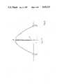
- FIG. 1is a top isometric view of a layered glass tube of the invention having a hollow center.
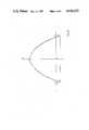
- FIG. 2is a sectional side view of the layered tube collapsed after being softened on exposure to a heat source.
- the softened collapsed sectionis shown as being drawn into a fiber.
- FIGS. 3 and 4are isometric end views of fibers wherein the rings represent layers having different indices of refraction.
- FIGS. 5 and 6are graphical representations of the indices of refraction over the cross section of an optical fiber produced by the prior art and by the present invention, respectively.
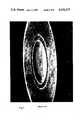
- FIGS. 7 and 8show a Scanning Electrobeam Microscope Photograph of the prior art and of the invention respectively.
- the tubular glass body shown in FIG. 1is composed of an outer jacket layer 1, consisting essentially of pure SiO 2 glass, and an inner core layer 2, consisting essentially of SiO 2 glass doped with GeO 2 .
- the GeO 2 contentincreases toward the center so that the desired gradient profile of the index of refraction is produced according to an exponential curve in the core of the glass fiber to be drawn.
- a heat source (burner or furnace) 3is used to heat the tubular glass body in a defined region 4 until the softening point is reached.
- the softened portionis drawn to form a glass fiber.
- a subatmospheric pressureis maintained of such magnitude that a dip formation in the glass fiber is prevented.
- the subatmospheric pressure in region 5is generated by conventional means, for example, by connecting a vacuum pump to opening 6.
- the wall thickness of the body relative to its inner diametermust be sufficiently large.
- a tube having a relatively large outer diameter and a relatively thin wall thickness, coated in its interior according to the VCVD (vertical chemical vapor-deposition) processwas initially precollapsed with an atmospheric internal pressure.
- the resulting GeO 2 deficient inner layerwas removed by etching.
- an internal subatmospheric pressure of, for example, 400 mbarwas maintained; accordingly, no GeO 2 deficient internal region was able to form in the fiber.
- the glass fibers produced according to prior art methodshave a dip 7 (reduced index of refraction) in their center, as shown in FIG. 3, the glass fibers produced according to the present invention, as shown in FIG. 4, do not exhibit a dip.
- the concentric rings in FIGS. 3 and 4represent concentric regions of varying index of refraction.
- FIG. 5is a refractive index curve for an optical fiber formed according to the methods of the prior art, exhibiting a dip 10 in refractive index at the center of the fiber.
- FIG. 6is a refractive index curve for an optical fiber formed by the process of the invention, exhibiting the maximum refractive index at the center of the fiber.
- FIG. 7shows the Scanning Electronbeam Microscope-Photograph of a fiber with an central dip. (Magnification 2000 fold)
- FIG. 8is the Scanning Electronbeam Microscope-Photograph of a fiber prepared by the process of the invention. (Magnification 10,000 fold)
Landscapes
- Chemical & Material Sciences (AREA)
- Engineering & Computer Science (AREA)
- Life Sciences & Earth Sciences (AREA)
- General Life Sciences & Earth Sciences (AREA)
- Geochemistry & Mineralogy (AREA)
- Manufacturing & Machinery (AREA)
- Materials Engineering (AREA)
- Organic Chemistry (AREA)
- Chemical Kinetics & Catalysis (AREA)
- General Chemical & Material Sciences (AREA)
- Manufacture, Treatment Of Glass Fibers (AREA)
- Glass Compositions (AREA)
Abstract
Description
Claims (19)
Applications Claiming Priority (4)
| Application Number | Priority Date | Filing Date | Title |
|---|---|---|---|
| DE3419835 | 1984-05-26 | ||
| DE3419835 | 1984-05-26 | ||
| DE19843447081DE3447081A1 (en) | 1984-05-26 | 1984-12-22 | METHOD FOR PRODUCING A PREFORM FOR DRAWING OPTICAL FIBERS |
| DE3447081 | 1984-12-22 |
Publications (1)
| Publication Number | Publication Date |
|---|---|
| US4636235Atrue US4636235A (en) | 1987-01-13 |
Family
ID=25821608
Family Applications (1)
| Application Number | Title | Priority Date | Filing Date |
|---|---|---|---|
| US06/737,170Expired - LifetimeUS4636235A (en) | 1984-05-26 | 1985-05-23 | Method for producing optical fibers |
Country Status (4)
| Country | Link |
|---|---|
| US (1) | US4636235A (en) |
| CA (1) | CA1259785A (en) |
| DE (1) | DE3447081A1 (en) |
| FI (1) | FI78671C (en) |
Cited By (31)
| Publication number | Priority date | Publication date | Assignee | Title |
|---|---|---|---|---|
| US4750926A (en)* | 1987-08-07 | 1988-06-14 | Corning Glass Works | Method of making precision shaped apertures in glass |
| US4772303A (en)* | 1985-06-25 | 1988-09-20 | The Furukawa Electric Co., Ltd. | Process for fabricating optical fiber |
| US4832721A (en)* | 1984-07-31 | 1989-05-23 | Furukawa Electric Co., Ltd. | Method of fabricating optical fiber base material |
| US4859222A (en)* | 1987-10-07 | 1989-08-22 | Schott Glaswerke | Method for the manufacture of a light wave guide |
| US4908053A (en)* | 1987-08-19 | 1990-03-13 | Non Oxide Glass Research And Development Co., Ltd. | Process for producing chalcogenide glass fiber |
| US5055120A (en)* | 1987-12-15 | 1991-10-08 | Infrared Fiber Systems, Inc. | Fluoride glass fibers with reduced defects |
| US5364429A (en)* | 1991-07-25 | 1994-11-15 | Alcatel Fibres Optiques | Method of manufacturing active optical fibers |
| US20020178761A1 (en)* | 2001-05-31 | 2002-12-05 | Cummings Jill A. | Method of low PMD optical fiber manufacture |
| US20030024278A1 (en)* | 2001-07-31 | 2003-02-06 | Berkey George E. | Method for fabricating a low polarization mode dispersion optical fiber |
| US20060140560A1 (en)* | 1999-04-26 | 2006-06-29 | Allen Martin W | Optical fiber and a method for fabricating a low polarization-mode dispersion and low attenuation optical fiber |
| US20090019894A1 (en)* | 2003-07-28 | 2009-01-22 | Draka Comteq B.V. | Method for Manufacturing a Multimode Optical Fibre |
| US20100021170A1 (en)* | 2008-06-23 | 2010-01-28 | Draka Comteq B.V. | Wavelength Multiplexed Optical System with Multimode Optical Fibers |
| US20100028020A1 (en)* | 2008-07-08 | 2010-02-04 | Draka Cornteq B.V. | Multimode Optical Fibers |
| US20100171945A1 (en)* | 2009-01-08 | 2010-07-08 | Draka Comteq B.V. | Method of Classifying a Graded-Index Multimode Optical Fiber |
| US20100254653A1 (en)* | 2007-10-23 | 2010-10-07 | Draka Comteq B.V. | Multimode Fiber |
| US20100310218A1 (en)* | 2009-06-05 | 2010-12-09 | Draka Comteq B.V. | Large Bandwidth Multimode Optical Fiber Having a Reduced Cladding Effect |
| US20110058781A1 (en)* | 2009-09-09 | 2011-03-10 | Draka Comteq, B.V. | Multimode Optical Fiber Having Improved Bending Losses |
| US20110064367A1 (en)* | 2009-09-17 | 2011-03-17 | Draka Comteq, B.V. | Multimode Optical Fiber |
| US20110123162A1 (en)* | 2009-11-25 | 2011-05-26 | Draka Comteq, B.V. | High-Bandwidth, Dual-Trench-Assisted Multimode Optical Fiber |
| US20110123161A1 (en)* | 2009-11-25 | 2011-05-26 | Draka Comteq B.V. | High-Bandwidth Multimode Optical Fiber with Reduced Cladding Effect |
| US20110135263A1 (en)* | 2009-12-03 | 2011-06-09 | Draka Comteq, B.V. | High-Bandwidth Multimode Optical Fiber Having Reduced Bending Losses |
| US20110135262A1 (en)* | 2009-12-03 | 2011-06-09 | Draka Comteq, B.V. | Multimode Optical Fiber with Low Bending Losses and Reduced Cladding Effect |
| US20110217012A1 (en)* | 2010-03-02 | 2011-09-08 | Draka Comteq B.V. | Broad-Bandwidth Multimode Optical Fiber Having Reduced Bending Losses |
| US8391661B2 (en) | 2011-01-31 | 2013-03-05 | Draka Comteq, B.V. | Multimode optical fiber |
| US8639079B2 (en) | 2011-03-29 | 2014-01-28 | Draka Comteq, B.V. | Multimode optical fiber |
| US8644664B2 (en) | 2011-01-31 | 2014-02-04 | Draka Comteq, B.V. | Broad-bandwidth optical fiber |
| US8879878B2 (en) | 2011-07-01 | 2014-11-04 | Draka Comteq, B.V. | Multimode optical fiber |
| US8891074B2 (en) | 2010-10-18 | 2014-11-18 | Draka Comteq, B.V. | Multimode optical fiber insensitive to bending losses |
| US9014525B2 (en) | 2009-09-09 | 2015-04-21 | Draka Comteq, B.V. | Trench-assisted multimode optical fiber |
| US9341771B2 (en) | 2011-03-24 | 2016-05-17 | Draka Comteq, B.V. | Bend-resistant multimode optical fiber |
| US9405062B2 (en) | 2011-04-27 | 2016-08-02 | Draka Comteq B.V. | High-bandwidth, radiation-resistant multimode optical fiber |
Families Citing this family (1)
| Publication number | Priority date | Publication date | Assignee | Title |
|---|---|---|---|---|
| US5672192A (en)* | 1996-05-30 | 1997-09-30 | Lucent Technologies Inc. | Method of making optical fiber using a plasma torch fiber-drawing furnace |
Citations (12)
| Publication number | Priority date | Publication date | Assignee | Title |
|---|---|---|---|---|
| US4121919A (en)* | 1977-02-18 | 1978-10-24 | Compagnie Generale D'electricite | Method of producing an optical fibre blank |
| DE2827303A1 (en)* | 1977-06-22 | 1979-01-04 | Corning Glass Works | METHOD FOR MANUFACTURING OPTICAL OBJECTS |
| DE2922665A1 (en)* | 1978-06-09 | 1979-12-20 | Int Standard Electric Corp | PROCESSING FOR THE PRODUCTION OF A MONOMODE FIBER OPERATING FIBER WITH ELLIPTICAL CORE CROSS SECTION |
| US4251251A (en)* | 1979-05-31 | 1981-02-17 | Corning Glass Works | Method of making optical devices |
| DE2938218A1 (en)* | 1979-09-21 | 1981-04-02 | Corning Glass Works, Corning, N.Y. | High purity glass objects, esp. optical waveguide fibres - made by CVD of two glass layers of mandrel using flame hydrolysis burner, then removing mandrel and collapsing layers by heating |
| DE3106412A1 (en)* | 1980-02-21 | 1981-12-24 | Nippon Telegraph & Telephone Public Corp., Tokyo | METHOD FOR PRODUCING OPTICAL FIBERS |
| DE3132010A1 (en)* | 1981-08-13 | 1983-03-03 | Licentia Patent-Verwaltungs-Gmbh, 6000 Frankfurt | Process for the production of polarisation-retaining optical fibres |
| EP0109192A1 (en)* | 1982-10-15 | 1984-05-23 | Hitachi, Ltd. | Method of producing optical fiber preform |
| DE3405812A1 (en)* | 1983-02-18 | 1984-08-23 | Hoya Corp., Tokio/Tokyo | Process for the production of a glass product having a refractive index gradient |
| DE3315165A1 (en)* | 1983-04-27 | 1984-10-31 | Licentia Patent-Verwaltungs-Gmbh, 6000 Frankfurt | Process for the production of an optical waveguide |
| US4486214A (en)* | 1983-12-08 | 1984-12-04 | At&T Technologies, Inc. | Methods of and apparatus for collapsing a preform tube into a preform from which lightguide fiber is drawn |
| US4551162A (en)* | 1984-10-01 | 1985-11-05 | Polaroid Corporation | Hollow tube method for forming an optical fiber |
- 1984
- 1984-12-22DEDE19843447081patent/DE3447081A1/ennot_activeWithdrawn
- 1985
- 1985-05-23FIFI852067Apatent/FI78671C/ennot_activeIP Right Cessation
- 1985-05-23USUS06/737,170patent/US4636235A/ennot_activeExpired - Lifetime
- 1985-05-24CACA000482307Apatent/CA1259785A/ennot_activeExpired
Patent Citations (13)
| Publication number | Priority date | Publication date | Assignee | Title |
|---|---|---|---|---|
| US4121919A (en)* | 1977-02-18 | 1978-10-24 | Compagnie Generale D'electricite | Method of producing an optical fibre blank |
| DE2827303A1 (en)* | 1977-06-22 | 1979-01-04 | Corning Glass Works | METHOD FOR MANUFACTURING OPTICAL OBJECTS |
| DE2922665A1 (en)* | 1978-06-09 | 1979-12-20 | Int Standard Electric Corp | PROCESSING FOR THE PRODUCTION OF A MONOMODE FIBER OPERATING FIBER WITH ELLIPTICAL CORE CROSS SECTION |
| US4251251A (en)* | 1979-05-31 | 1981-02-17 | Corning Glass Works | Method of making optical devices |
| DE2938218A1 (en)* | 1979-09-21 | 1981-04-02 | Corning Glass Works, Corning, N.Y. | High purity glass objects, esp. optical waveguide fibres - made by CVD of two glass layers of mandrel using flame hydrolysis burner, then removing mandrel and collapsing layers by heating |
| DE3106412A1 (en)* | 1980-02-21 | 1981-12-24 | Nippon Telegraph & Telephone Public Corp., Tokyo | METHOD FOR PRODUCING OPTICAL FIBERS |
| DE3132010A1 (en)* | 1981-08-13 | 1983-03-03 | Licentia Patent-Verwaltungs-Gmbh, 6000 Frankfurt | Process for the production of polarisation-retaining optical fibres |
| EP0109192A1 (en)* | 1982-10-15 | 1984-05-23 | Hitachi, Ltd. | Method of producing optical fiber preform |
| US4505729A (en)* | 1982-10-15 | 1985-03-19 | Hitachi, Ltd. | Method of producing optical fiber preform |
| DE3405812A1 (en)* | 1983-02-18 | 1984-08-23 | Hoya Corp., Tokio/Tokyo | Process for the production of a glass product having a refractive index gradient |
| DE3315165A1 (en)* | 1983-04-27 | 1984-10-31 | Licentia Patent-Verwaltungs-Gmbh, 6000 Frankfurt | Process for the production of an optical waveguide |
| US4486214A (en)* | 1983-12-08 | 1984-12-04 | At&T Technologies, Inc. | Methods of and apparatus for collapsing a preform tube into a preform from which lightguide fiber is drawn |
| US4551162A (en)* | 1984-10-01 | 1985-11-05 | Polaroid Corporation | Hollow tube method for forming an optical fiber |
Cited By (52)
| Publication number | Priority date | Publication date | Assignee | Title |
|---|---|---|---|---|
| US4832721A (en)* | 1984-07-31 | 1989-05-23 | Furukawa Electric Co., Ltd. | Method of fabricating optical fiber base material |
| US4772303A (en)* | 1985-06-25 | 1988-09-20 | The Furukawa Electric Co., Ltd. | Process for fabricating optical fiber |
| US4750926A (en)* | 1987-08-07 | 1988-06-14 | Corning Glass Works | Method of making precision shaped apertures in glass |
| US4908053A (en)* | 1987-08-19 | 1990-03-13 | Non Oxide Glass Research And Development Co., Ltd. | Process for producing chalcogenide glass fiber |
| US4859222A (en)* | 1987-10-07 | 1989-08-22 | Schott Glaswerke | Method for the manufacture of a light wave guide |
| US5055120A (en)* | 1987-12-15 | 1991-10-08 | Infrared Fiber Systems, Inc. | Fluoride glass fibers with reduced defects |
| US5364429A (en)* | 1991-07-25 | 1994-11-15 | Alcatel Fibres Optiques | Method of manufacturing active optical fibers |
| US20060140560A1 (en)* | 1999-04-26 | 2006-06-29 | Allen Martin W | Optical fiber and a method for fabricating a low polarization-mode dispersion and low attenuation optical fiber |
| US7672557B2 (en) | 1999-04-26 | 2010-03-02 | Corning Incorporated | Optical fiber and a method for fabricating a low polarization-mode dispersion and low attenuation optical fiber |
| US20020178761A1 (en)* | 2001-05-31 | 2002-12-05 | Cummings Jill A. | Method of low PMD optical fiber manufacture |
| US20030024278A1 (en)* | 2001-07-31 | 2003-02-06 | Berkey George E. | Method for fabricating a low polarization mode dispersion optical fiber |
| US6883351B2 (en) | 2001-07-31 | 2005-04-26 | Corning Incorporated | Method for fabricating a low polarization mode dispersion optical fiber |
| US20090019894A1 (en)* | 2003-07-28 | 2009-01-22 | Draka Comteq B.V. | Method for Manufacturing a Multimode Optical Fibre |
| US9459400B2 (en) | 2003-07-28 | 2016-10-04 | Draka Comteq, B.V. | Multimode optical fibre |
| US8794038B2 (en) | 2003-07-28 | 2014-08-05 | Draka Comteq, B.V. | Method for manufacturing a multimode optical fibre |
| US8009950B2 (en) | 2007-10-23 | 2011-08-30 | Draka Comteq, B.V. | Multimode fiber |
| US20100254653A1 (en)* | 2007-10-23 | 2010-10-07 | Draka Comteq B.V. | Multimode Fiber |
| US8724950B2 (en) | 2007-10-23 | 2014-05-13 | Draka Comteq, B.V. | Multimode fiber |
| US20100021170A1 (en)* | 2008-06-23 | 2010-01-28 | Draka Comteq B.V. | Wavelength Multiplexed Optical System with Multimode Optical Fibers |
| US8879920B2 (en) | 2008-06-23 | 2014-11-04 | Draka Comteq, B.V. | Wavelength multiplexed optical system with multimode optical fibers |
| US8260103B2 (en) | 2008-07-08 | 2012-09-04 | Draka Comteq, B.V. | Multimode optical fibers |
| US7995888B2 (en) | 2008-07-08 | 2011-08-09 | Draka Comteq, B.V. | Multimode optical fibers |
| US20100028020A1 (en)* | 2008-07-08 | 2010-02-04 | Draka Cornteq B.V. | Multimode Optical Fibers |
| US8432539B2 (en) | 2009-01-08 | 2013-04-30 | Draka Comteq B.V. | Graded-index multimode optical fiber |
| US20100171945A1 (en)* | 2009-01-08 | 2010-07-08 | Draka Comteq B.V. | Method of Classifying a Graded-Index Multimode Optical Fiber |
| US8274647B2 (en) | 2009-01-08 | 2012-09-25 | Draka Comteq, B.V. | Method of classifying a graded-index multimode optical fiber |
| US20100310218A1 (en)* | 2009-06-05 | 2010-12-09 | Draka Comteq B.V. | Large Bandwidth Multimode Optical Fiber Having a Reduced Cladding Effect |
| US8867880B2 (en) | 2009-06-05 | 2014-10-21 | Draka Comteq, B.V. | Large bandwidth multimode optical fiber having a reduced cladding effect |
| US9014525B2 (en) | 2009-09-09 | 2015-04-21 | Draka Comteq, B.V. | Trench-assisted multimode optical fiber |
| US20110058781A1 (en)* | 2009-09-09 | 2011-03-10 | Draka Comteq, B.V. | Multimode Optical Fiber Having Improved Bending Losses |
| US8520993B2 (en) | 2009-09-09 | 2013-08-27 | Draka Comteq, B.V. | Multimode optical fiber having improved bending losses |
| US20110064367A1 (en)* | 2009-09-17 | 2011-03-17 | Draka Comteq, B.V. | Multimode Optical Fiber |
| US8340488B2 (en) | 2009-09-17 | 2012-12-25 | Draka Comteq, B.V. | Multimode optical fiber |
| US8385704B2 (en) | 2009-11-25 | 2013-02-26 | Draka Comteq Bv | High-bandwidth multimode optical fiber with reduced cladding effect |
| US20110123161A1 (en)* | 2009-11-25 | 2011-05-26 | Draka Comteq B.V. | High-Bandwidth Multimode Optical Fiber with Reduced Cladding Effect |
| US8483535B2 (en) | 2009-11-25 | 2013-07-09 | Draka Comteq B.V. | High-bandwidth, dual-trench-assisted multimode optical fiber |
| US20110123162A1 (en)* | 2009-11-25 | 2011-05-26 | Draka Comteq, B.V. | High-Bandwidth, Dual-Trench-Assisted Multimode Optical Fiber |
| US8280213B2 (en) | 2009-11-25 | 2012-10-02 | Draka Comteq, B.V. | High-bandwidth multimode optical fiber with reduced cladding effect |
| US8428410B2 (en) | 2009-12-03 | 2013-04-23 | Draka Comteq B.V. | High-bandwidth multimode optical fiber having reduced bending losses |
| US20110135262A1 (en)* | 2009-12-03 | 2011-06-09 | Draka Comteq, B.V. | Multimode Optical Fiber with Low Bending Losses and Reduced Cladding Effect |
| US8406593B2 (en) | 2009-12-03 | 2013-03-26 | Draka Comteq B.V. | Multimode optical fiber with low bending losses and reduced cladding effect |
| US20110135263A1 (en)* | 2009-12-03 | 2011-06-09 | Draka Comteq, B.V. | High-Bandwidth Multimode Optical Fiber Having Reduced Bending Losses |
| US8565568B2 (en) | 2010-03-02 | 2013-10-22 | Draka Comteq, B.V. | Broad-bandwidth multimode optical fiber having reduced bending losses |
| US20110217012A1 (en)* | 2010-03-02 | 2011-09-08 | Draka Comteq B.V. | Broad-Bandwidth Multimode Optical Fiber Having Reduced Bending Losses |
| US8891074B2 (en) | 2010-10-18 | 2014-11-18 | Draka Comteq, B.V. | Multimode optical fiber insensitive to bending losses |
| US8644664B2 (en) | 2011-01-31 | 2014-02-04 | Draka Comteq, B.V. | Broad-bandwidth optical fiber |
| US8391661B2 (en) | 2011-01-31 | 2013-03-05 | Draka Comteq, B.V. | Multimode optical fiber |
| US9341771B2 (en) | 2011-03-24 | 2016-05-17 | Draka Comteq, B.V. | Bend-resistant multimode optical fiber |
| US9671553B2 (en) | 2011-03-24 | 2017-06-06 | Draka Comteq, B.V. | Bend-resistant multimode optical fiber |
| US8639079B2 (en) | 2011-03-29 | 2014-01-28 | Draka Comteq, B.V. | Multimode optical fiber |
| US9405062B2 (en) | 2011-04-27 | 2016-08-02 | Draka Comteq B.V. | High-bandwidth, radiation-resistant multimode optical fiber |
| US8879878B2 (en) | 2011-07-01 | 2014-11-04 | Draka Comteq, B.V. | Multimode optical fiber |
Also Published As
| Publication number | Publication date |
|---|---|
| CA1259785A (en) | 1989-09-26 |
| FI852067L (en) | 1985-11-27 |
| FI852067A0 (en) | 1985-05-23 |
| FI78671C (en) | 1989-09-11 |
| FI78671B (en) | 1989-05-31 |
| DE3447081A1 (en) | 1985-12-19 |
Similar Documents
| Publication | Publication Date | Title |
|---|---|---|
| US4636235A (en) | Method for producing optical fibers | |
| US4636236A (en) | Method for producing a preform for drawing optical fibers | |
| US4229070A (en) | High bandwidth optical waveguide having B2 O3 free core and method of fabrication | |
| US4230396A (en) | High bandwidth optical waveguides and method of fabrication | |
| US4385802A (en) | Long wavelength, low-loss optical waveguide | |
| US4339174A (en) | High bandwidth optical waveguide | |
| US4360371A (en) | Method of making polarization retaining single-mode optical waveguide | |
| EP0198510B1 (en) | Method of producing glass preform for optical fiber | |
| US4415230A (en) | Polarization retaining single-mode optical waveguide | |
| KR900002047B1 (en) | Preparation method of preform for optical fibers | |
| KR100688631B1 (en) | Method for manufacturing preform for substrate tube and optical fiber | |
| US4500168A (en) | Single polarization optical fibers | |
| US5048923A (en) | Image fiber, image fiber preform, and manufacturing processes thereof | |
| JP2965520B2 (en) | Manufacturing method of dispersion moving optical fiber | |
| US5090979A (en) | Method of manufacturing an optical fiber preform having doped cladding | |
| GB2104241A (en) | Single polarization optical fibres | |
| US20080028799A1 (en) | Optical fiber preform manufacturing method | |
| GB2123810A (en) | Fabrication of single polarization optical fibres | |
| US4318726A (en) | Process for producing optical fiber preform | |
| EP0039991B1 (en) | Optical waveguide preform and process for the manufacture thereof | |
| EP0111901B1 (en) | Process for eliminating the axial refractive index depression in optical fibres | |
| JP2003531796A (en) | Method of manufacturing substrate tube and optical fiber preform | |
| EP0907618B1 (en) | Method of making polarization retaining fiber | |
| JPS60255640A (en) | Manufacture of drawing optical fiber mother material | |
| JPS60255642A (en) | Manufacture of optical fiber |
Legal Events
| Date | Code | Title | Description |
|---|---|---|---|
| AS | Assignment | Owner name:AEG TELEFUNKEN KABELWERKE AG., RHEYDT, BONNENBROIC Free format text:ASSIGNMENT OF ASSIGNORS INTEREST.;ASSIGNORS:GLESSNER, BERTRAM;PITSCH, PAUL;HEINEN, PETER;AND OTHERS;REEL/FRAME:004439/0343;SIGNING DATES FROM 19850624 TO 19850718 | |
| STCF | Information on status: patent grant | Free format text:PATENTED CASE | |
| FEPP | Fee payment procedure | Free format text:PAYOR NUMBER ASSIGNED (ORIGINAL EVENT CODE: ASPN); ENTITY STATUS OF PATENT OWNER: LARGE ENTITY | |
| FPAY | Fee payment | Year of fee payment:4 | |
| FEPP | Fee payment procedure | Free format text:PAYER NUMBER DE-ASSIGNED (ORIGINAL EVENT CODE: RMPN); ENTITY STATUS OF PATENT OWNER: LARGE ENTITY Free format text:PAYOR NUMBER ASSIGNED (ORIGINAL EVENT CODE: ASPN); ENTITY STATUS OF PATENT OWNER: LARGE ENTITY | |
| FPAY | Fee payment | Year of fee payment:8 | |
| FEPP | Fee payment procedure | Free format text:PAYER NUMBER DE-ASSIGNED (ORIGINAL EVENT CODE: RMPN); ENTITY STATUS OF PATENT OWNER: LARGE ENTITY Free format text:PAYOR NUMBER ASSIGNED (ORIGINAL EVENT CODE: ASPN); ENTITY STATUS OF PATENT OWNER: LARGE ENTITY | |
| FPAY | Fee payment | Year of fee payment:12 | |
| AS | Assignment | Owner name:ALCATEL, FRANCE Free format text:ASSIGNMENT OF ASSIGNORS INTEREST;ASSIGNOR:KABEL RHEYDT AG;REEL/FRAME:012153/0253 Effective date:20010425 Owner name:KABEL RHEYDT AG, GERMANY Free format text:CHANGE OF NAME;ASSIGNOR:AEG-TELEFUNKEN KABELWERKE AG;REEL/FRAME:012153/0258 Effective date:19920724 |