US4635642A - Medical electrode with reusable conductor - Google Patents
Medical electrode with reusable conductorDownload PDFInfo
- Publication number
- US4635642A US4635642AUS06/756,752US75675285AUS4635642AUS 4635642 AUS4635642 AUS 4635642AUS 75675285 AUS75675285 AUS 75675285AUS 4635642 AUS4635642 AUS 4635642A
- Authority
- US
- United States
- Prior art keywords
- electrode
- socket
- bore
- gel matrix
- conductor
- Prior art date
- Legal status (The legal status is an assumption and is not a legal conclusion. Google has not performed a legal analysis and makes no representation as to the accuracy of the status listed.)
- Expired - Lifetime
Links
Images

Classifications
- A—HUMAN NECESSITIES
- A61—MEDICAL OR VETERINARY SCIENCE; HYGIENE
- A61B—DIAGNOSIS; SURGERY; IDENTIFICATION
- A61B5/00—Measuring for diagnostic purposes; Identification of persons
- A61B5/24—Detecting, measuring or recording bioelectric or biomagnetic signals of the body or parts thereof
- A61B5/25—Bioelectric electrodes therefor
- A61B5/251—Means for maintaining electrode contact with the body
- A61B5/257—Means for maintaining electrode contact with the body using adhesive means, e.g. adhesive pads or tapes
- A61B5/259—Means for maintaining electrode contact with the body using adhesive means, e.g. adhesive pads or tapes using conductive adhesive means, e.g. gels
- A—HUMAN NECESSITIES
- A61—MEDICAL OR VETERINARY SCIENCE; HYGIENE
- A61B—DIAGNOSIS; SURGERY; IDENTIFICATION
- A61B2562/00—Details of sensors; Constructional details of sensor housings or probes; Accessories for sensors
- A61B2562/02—Details of sensors specially adapted for in-vivo measurements
- A61B2562/0209—Special features of electrodes classified in A61B5/24, A61B5/25, A61B5/283, A61B5/291, A61B5/296, A61B5/053
- A61B2562/0215—Silver or silver chloride containing
- A—HUMAN NECESSITIES
- A61—MEDICAL OR VETERINARY SCIENCE; HYGIENE
- A61B—DIAGNOSIS; SURGERY; IDENTIFICATION
- A61B2562/00—Details of sensors; Constructional details of sensor housings or probes; Accessories for sensors
- A61B2562/02—Details of sensors specially adapted for in-vivo measurements
- A61B2562/0209—Special features of electrodes classified in A61B5/24, A61B5/25, A61B5/283, A61B5/291, A61B5/296, A61B5/053
- A61B2562/0217—Electrolyte containing
- A—HUMAN NECESSITIES
- A61—MEDICAL OR VETERINARY SCIENCE; HYGIENE
- A61B—DIAGNOSIS; SURGERY; IDENTIFICATION
- A61B2562/00—Details of sensors; Constructional details of sensor housings or probes; Accessories for sensors
- A61B2562/12—Manufacturing methods specially adapted for producing sensors for in-vivo measurements
- A61B2562/125—Manufacturing methods specially adapted for producing sensors for in-vivo measurements characterised by the manufacture of electrodes
Definitions
- the present inventionrelates to a medical electrode for transmitting electrical signals between the skin of a subject, such as a medical patient, and peripheral equipment for monitoring signals derived from the skin of the patient.
- This inventionmay, however, also be used for medical electrodes for applying stimulation signals to the skin of the patient.
- a primary object of this inventionis to provide an inexpensive, high quality medical electrode.
- Electrode conductorsusually comprise the most expensive part of a medical electrode so that, by providing a reusable electrode conductor, substantial economies may be had because the more expensive conductor may be reused many times while the less expensive electrode pad is discarded after each use.
- This inventiontakes advantage of this approach and it is a further object of this invention to provide an improved high quality but inexpensive and disposable electrolyte pad comprising an electrolyte and a carrier therefor.
- an electrode of the type having a reusable conductoris the manner in which the conductor is attached to the electrode pad.
- several electrode padsare adhered to the skin of a patient and the electrode conductors are thereafter connected to the pads.
- Such connections, and subsequent disconnections,should be readily made without causing discomfort to the patient.
- the connectionshould be sufficiently secure that the electrode conductor is held firmly engaged with the electrolyte. Therefore, it is a further object of this invention to provide a medical electrode of the type comprising a reusable conductor and a disposable electrode pad having an improved connection between the conductor and the electrode pad whereby the conductor can be easily and securely engaged with the electrolyte.
- a medical electrodehaving an electrode pad comprising a laminated assembly of a pair of spaced, flexible, electrically non-conductive, foam sheets with patient-contacting adhesive layers on their lower surfaces.
- the gap between the foam sheetsis filled with an electrolyte gel matrix, preferably a conductive adhesive, a urethane hydrogel being the material of choice, having a thickness greater than the foam sheets.
- the electrode padfurther comprises an electrically non-conductive socket plate overlying the gel matrix and overlapping the foam sheets.
- the socket platehas an adhesive layer on its bottom surface adhered to the foam pads and the gel matrix and is provided with a socket for connection of the electrode conductor to external monitoring equipment.
- the socketpreferably comprises a bore centrally located over the gel matrix and shaped to receive the electrode conductor.
- the electrode conductoris slightly larger than the bore, and the adjacent area of the socket plate resiliently holds the electrode conductor therein.
- the socketfurther includes radially extending slits projecting from the outer margins of the bore.
- the electrode conductoris attached to a reusable lead wire having a jack for connection to external monitoring equipment.
- the electrode conductormay be provided with a snap fastener-type stud.
- the electrode conductorhas a ridged body so constructed that the portions of the socket plate surrounding the bore resiliently engage the conductor between its ridges and thereby maintain the conductor in engagement with the electrolyte matrix.
- the socket and the electrode conductorare provided with a cooperating key and keyway for restraining relative movements therebetween.
- a strip of electrode padsis mounted on an elongate release liner or a formed tray with adjacent electrodes abutting one another.
- the foam sheetsinitially comprise adhesively coated webs or strips of indefinite length laid along the opposite margins of the release liner or formed tray and the gel matrix is deposited as a continuous strip on the release liner between the foam strips.
- the socket plates for the electrode pad stripare formed from a web of relatively stiff, adhesively coated, plastic sheet material from which the sockets have been die cut and which is laid over the foam strips and the deposited gel matrix. The parts thus assembled are then die cut to shape and to separate the individual electrodes and to sever the parts into separate electrode pad strips.
- Electrode pads formed in this mannerhave their electrolyte exposed both through the sockets and along their sides.
- the individual strip of electrode padsis preferably packaged in an air tight envelope or the like.
- electrolyte dry outis not a matter of concern. Therefore, the fact that the gel matrix is exposed along the side edges of an electrode pad does not detract from the utility of the electrode.
- each electrode padis preferably constructed so that, when applied to the skin of a patient, its gel matrix is confined so as to avoid dry out.
- FIG. 1is a perspective view of a single medical electrode pad of this invention, a lead wire therefor, portions of which have been broken away, and an electrode conductor.
- FIG. 2is an enlarged, fragmentary, cross-sectional view of the medical electrode pad, the lead wire, and the electrode conductor taken generally on line 2--2 of FIG. 1.
- FIG. 3is a fragmentary, cross-sectional view, on the same scale as FIG. 2, of a portion of the electrode pad of FIG. 1 and showing the electrode conductor operatively connected thereto.
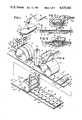
- FIG. 4is a perspective view schematically illustrating steps taken in the preferred method of manufacturing a plurality of medical electrode pads in a strip in accordance with this invention.
- FIG. 5is a perspective view, with parts broken away, of a completed electrode pad strip in accordance with this invention and showing, by phantom lines, an air tight package for the strip.
- FIG. 6is a perspective view of a modified medical electrode pad in accordance with this invention.
- FIG. 7is a plan view of a second modified medical electrode pad in accordance with this invention.
- FIG. 8is an exploded perspective view of the electrode pad of FIG. 7 and a lead wire provided with a modified electrode conductor in accordance with this invention.
- a medical electrode according to the present inventionincludes a disposable electrolyte carrier or electrode pad generally designated 10 which comprises a laminated assembly of a pair of spaced, parallel, flexible, sheets of foam plastic, designated 12 and 14, respectively, having adhesive layers 16 and 18, respectively, on their lower surfaces.
- the sheets 12 and 14are made from electrically non-conductive foam material and may comprise any of a wide variety of closed cell thermoplastic foams which are well known in the art, the material of choice for the present invention being a polyethylene foam.
- Adhesive layers 16 and 18may comprise any conventional electrically non-conductive pressure sensitive adhesive of the type generally known as "patient contact" adhesives which may be safely used to affix the electrode pad 10 to the skin of a patient.
- the gap between the foam sheets 12 and 14is filled with a matrix 20 of electrolyte gel, the gel matrix 20 preferably comprising a conductive adhesive and having a thickness greater than the foam sheets 12 and 14.
- a matrix 20 of electrolyte gelpreferably comprising a conductive adhesive and having a thickness greater than the foam sheets 12 and 14.
- the material of choice for the present applicationis a urethane hydrogel which is of a gelatinous consistency and which contains an electrolyte in an amount sufficient to render it electrically conductive.
- the electrolytecomprises an ionizable salt compatible with the metal used to form the electrode conductor which will be described below. These are well known in the art; examples are the use of sodium chloride when the conductor is made from or coated with silver, as is presently preferred, and the use of sodium sulfate with stainless steel.
- Alternate materials that may be used for the electrolyteinclude a commercially available conductive adhesive composition comprising karaya gum modified with sodium chloride, available from LecTec Corporation, 120 South Crosstown Circle, Eden Prairie, Minn.
- a commercially available conductive adhesive compositioncomprising karaya gum modified with sodium chloride, available from LecTec Corporation, 120 South Crosstown Circle, Eden Prairie, Minn.
- Various other conductive adhesive compositions that may be usableare described in the following U.S. Pat. Nos.: Marks et al. 3,357,930; Kater 2,993,049: Berg 4,066,076: Hymes 4,125,110: Cross et al. 4,141,366: and Hymes 4,274,420.
- Whatever the composition of the conductive adhesiveit should be of the type which will adhere to the skin of a patient and will have a cohesive strength sufficient to substantially maintain its shape and to permit it to be peeled from the skin to which it is attached without leaving any appreciable residue.
- socket plate 22Overlying the gel matrix 20 and overlapping the foam sheets 12 and 14 is a socket plate 22 that has an electrically non-conductive, pressure-sensitive, adhesive layer 24 on its bottom surface by which it is adhered to the foam sheets 12 and 14 and the gel matrix 20. Socket plate 22 and its underlying adhesive 24 perform the functions of maintaining the shape of the electrode pad 10, of providing a covering for the gel matrix 20, and of providing a socket 26, in the form of a centrally located, circular bore extending through the socket plate 22, for connection of the electrode pad 10 to external monitoring equipment.
- the socket plate 22comprises a relatively stiff sheet of electrically non-conductive thermoplastic material such as styrene, vinyl, or polyethylene terephthalate (Mylar).
- the socket plate 22should be resiliently flexible but sufficiently stiff that it will firmly hold the electrode conductor within the socket 26 as will be described below.
- Mylar sheet having a thickness of approximately 4 or 5 mils or vinyl sheet of approximately 5 or 6 milsare examples of materials from which the socket plate 22 could be made.
- a reusable lead wirehaving a jack 34 for electrical connection of the electrode pad 10 to external monitoring equipment is provided with an electrode conductor 36 adapted to extend through and be retained by the socket 26 so that it is lodged in the gel matrix 20 as shown in FIG. 3.
- the lead wire 32may be of the type conventionally used to connect external equipment to medical electrodes having snap fastener studs, and includes a jacketed cable 38 connected to a lead wire connector 40, which is shaped as a female snap fastener socket, by wiring 42 inside a molded head member 44.
- An insulating plastic sleeve 46covers the area where the exposed cable is crimped to the jack 34.
- the electrode conductor 36preferably comprises a one-piece, generally cylindrical conductive body having a snap fastener-type stud 48 formed on and projecting upwardly from the top surface of its generally cylindrical body. Since, in the contemplated use of this invention, the electrode pad 10 will be discarded after each use but the lead wire 32 with its electrode conductor 36 will be repeatedly used with like electrode pads, it is intended that the electrode conductor 36 will be permanently assembled on the lead wire head member 44. Therefore, the stud 48 is preferably slightly larger than conventional studs with which the female socket 40 is designed for use so that the stud 48 will be so tightly held in the socket 40 that separation of the electrode conductor 36 from the lead wire head member 44 would be difficult. As an option, the electrode conductor 36 could be permanently connected to the remainder of the lead wire 32. Various ways of making such a permanent connection will be readily apparent.
- the electrode conductor 36comprise substantially pure silver or be plated or coated with substantially pure silver and that its outer surface be chlorided.
- the presently preferred electrode conductorcomprises a conductive nylon, rendered conductive by inclusion of carbon, that preferably has a silver coating, which may be painted or plated, at least along a portion of its surface that engages the gel matrix 20. It would also be possible to use a silver plated non-conductive plastic, such as ABS, but it is believed that such an electrode conductor may have a sufficient portion of its silver plating removed by abrasion resulting from repeated applications to the electrode pads that the continuity of the silver plating may be lost so quickly that the useful life of the electrode conductor would be unsatisfactorily limited. Other metals could be used, such as stainless steel, but silver provides the highest quality traces.
- the cylindrical body of the illustrated electrode conductor 36has a concave bottom surface 50, a beveled lower outer wall 52 in the form of an inverted, truncated cone, sloping upwardly and outwardly from the bottom surface 50 that terminates at its upper end in a circular ridge or shoulder 54.
- a circular ridge or shoulder 54Above the ridge or shoulder 54, there are plural additional circular ridges or shoulders 56 formed at the upper ends of each of plural body sections that also are in the form of inverted, truncated cones but which have a lesser height than the lower wall surface 52.
- the portion of the outer wall of the body of the electrode conductor 36 extending out of the head member 44has plural, closely-spaced, parallel ridges or shoulders 54 and 56 separated by plural grooves, designated 58.
- the ridges or shoulders 54 and 56have a diameter slightly greater, on the order of 0.010 to 0.020 inch, than the diameter of the socket bore 26.
- an electrode pad having a socket bore diameter of approximately 0.344 inchmay be used with an electrode conductor having an outermost ridge diameter of approximately 0.355 inch.
- an electrode pad 10 of this inventionis adhered to the skin of a patient utilizing primarily the adhesive layers 16 and 18 on the bottom surfaces of the foam sheets 12 and 14 and also utilizing the inherent tackiness of the gel matrix 20.
- the lead wire 32is then connected to the electrode pad 10 by inserting the lower portion of the electrode conductor 36 through the bore 26 and into the area occupied by the gel matrix. As shown in FIG.
- the beveled lower outer wall 52 of the electrode conductor 36pushes the margins of the socket bore 26 downwardly as the electrode conductor 36 is inserted therein.
- the socket plate 22is resiliently flexible and because the electrode conductor 36 is only minimally larger than the bore 26.
- the ridge 54passes the bore 26 and, due to the resiliency of the socket plate 22, the margin of the bore 26 is biased to enter the groove 58 immediately above the lowest shoulder 54.
- the bottom surface 50 of the electrode conductor 36is made concave to provide a pocket for receiving the gel.
- FIG. 3shows the electrode conductor 36 inserted into the bore 26 of the electrode pad 10, but the electrode pad 10 is not shown applied to the skin of a patient. In practice, such would ordinarily not be done. Also, it may be noted that, although the margins of the bore 26 are shown lodged in the groove 58 immediately above the lowest shoulder 54, the electrode conductor 36 could be inserted more deeply into the area of the gel matrix 20.
- the lead wire 32may also be provided with an insulating washer 60 for preventing the gel material from reaching the lead wire connector 40.
- the washer 60could be integral with the electrode conductor 36 and there may be occasions, depending upon the construction of the lead wire head member 44 or the nature of the gel matrix, when it would not be needed.
- the electrode pad 10would be mounted on a release liner or silicon coated formed tray covering the adhesive layers 16 and 18 and the lower surface of the gel matrix 20 from which the electrode pad 10 would be removed immediately prior to use.
- the electrode pad 10is intended primarily for use in short term applications, such as for ECGs accomplished while a patient is at rest. For such applications, it is common practice to use ten, twelve, or fourteen electrodes at a time.
- an electrode strip 62be formed from the desired number of electrode pads 10 and from a release liner 64 on which the electrode pads 10 are located in mutually abutting, side-by-side relation.
- the release liner 64may comprise an elongate strip of silicon coated paper, styrene, or the like formed with planar upper surface portions 66 on which the foam pads 12 and 14 rest, and further formed with a recessed central portion forming an axially extending trough 68 filled by the gel matrix 20.
- the electrode strip 62is preferably packaged for shipment and storage in a substantially air and moisture vapor impervious package or envelope shown by phantom lines 70, which may, as conventional, be made from a plastic and metal foil laminate. It will be observed that the gel matrix 20, which is susceptible to drying-out, is exposed to ambient atmosphere at the ends of the electrode strip 62. This is acceptable provided the electrode strip 62 is retained in a substantially air and water vapor impervious package as described until shortly before use since drying out is thereby avoided.
- a preferred method of manufacturing plural electrode strips 62 on a continuous basisis schematically illustrated in highly simplified form in FIG. 4.
- two adhesively coated foam strips or webs 12' and 14' of indefinite lengthhave been preassembled onto a pair of release liners 71 and are continuously fed to a foam laminating roller 72 and a cooperating stripper roller 74 that strips away the release liner 71.
- the rollers 72 and 74may be rotatably driven in any suitable way.
- the laminates of the adhesively coated foam strips 12' and 14' on the release liner 71are preferably previously formed and wound into coils (not shown) from which they are drawn to the rollers 72 and 74 as they rotate.
- a strip 64' of release liner material of indefinite lengthwhich may be supported by rolls or the like (not shown), is coursed along a path extending beneath the foam laminating roller 72 so that the foam webs 12' and 14' are laid along the opposite top sides of the release liner strip 64' beside the trough 68. Thereafter, the release liner strip 64' passes beneath a funnel or other means 76 which deposits a strip of electrolyte material, designated 20', that forms the gel matrix 20 into the trough 68.
- This assemblythen passes under a power driven socket sheet laminating roller 77 to which is fed an assembly comprising a release liner 78 and a web of adhesively coated, relatively stiff, plastic sheet material 22' that is used to form the socket plates 22 and their underlying adhesive layers 24, which web 22' is placed over the previously assembled release liner strip 64' and electrolyte material 20'.
- the release liner 78 and the adhesively coated web 22'are preferably preassembled and then die cut to form the socket bores 26 in equally spaced relation along the entire length thereof.
- This assemblyis then wound into a coil (not shown) from which it is fed to the laminating roller 77.
- a stripper roller 79cooperates with the laminating roller 77 to strip away the release liner 78.
- the web 22'could be narrower than the release liner strip 64' and does not necessarily have to completely cover the foam sheets 12 and 14 of a completed electrode pad 10. Some convenience in handling the laminate is achieved if the web 22' is the same width as the release liner strip 64' and such construction is preferred.
- each electrode 10is preferably formed to the generally oval configuration illustrated, with straight sides and rounded ends, since electrodes of such shape are readily die cut from an elongate laminate strip with minimal wastage of material.
- the cutting elements 82are sized and shaped to cut through the entire laminate except for the release liner strip 64'.
- An appropriate cutter(not shown) is used to cut through the entire laminate, including the release liner strip 64', to form successive electrode strips 66 of the proper length.
- Such cutter meanscould be formed on the roller die 80 or may be separate therefrom.
- the gel material 20'is deposited in the trough 68 in a free-flowing, liquid state and permitted to set to a gelatinous, shape-retaining, state in the trough 68.
- the barriers 86are shown above the trough 68. In practice, they would be inserted into the trough 68 in advance of the depositing means 76.
- the barrierscould be made from thin plastic or the like and could either be left in the trough 68 or removed after the gel material has set sufficiently to retain its shape.
- the release linercould be formed with integral barriers.
- FIG. 6shows a modified electrode pad 10A which has the same general construction as the pad 10 of FIG. 1, and like reference numbers are used for like parts in FIG. 1 and FIG. 6.
- the socket 26Aincludes a circular bore 90 and four, equally spaced, radially extending slits 92 projection from the outer margin of the bore 90. Because of the slits 92, the arcuate portions of the socket plate 22A immediately adjacent the bore 90 are effectively formed to have four flaps, designated 94, which are effectively resiliently hinged to adjacent parts of the socket plate 22' and, accordingly, readily bend downwardly as the electrode conductor 36 is inserted into the bore 92.
- FIGS. 7 and 8show an electrode pad 100 and a lead wire 102 suitable for longer term monitoring, such as may be practiced when monitoring a patient for several days in a hospital.
- Electrode pad 100comprises a ring shaped, foam plastic body 104 made from closed cell polyethylene foam or the like having a patient-contacting, pressure sensitive adhesive layer 106 on its underside for attachment to the skin of a patient.
- the body 104has a central bore 108 which receives a portion of a gel matrix 110, which may be made from the same material as the gel matrix 20 of the first embodiment, that, before use, also extends into a pocket 112 formed in the center of a protective cover 114 engaged with the adhesive layer 106.
- the cover 114performs essentially the same function and may be constructed of the same material as the release liner 22.
- the adhesive 106is covered along a peripheral portion thereof by a suitably shaped finger tab 116 to facilitate removal of the foam plastic body 104 from the protective cover 114.
- the cover 114has an embossed arrow 118 to indicate the position of the finger tab 116.
- a circular socket plate 120Centrally located over the the foam body 104 is a circular socket plate 120 having an adhesive layer 122 on its lower surface attaching the socket plate 120 to the foam body 104 and the gel matrix 110.
- Socket plate 120which may be made from the same stiff sheet material as the socket plate 22 of the first embodiment, is provided with a socket 124 comprising a centrally located bore 126 having a circular center portion and a radially extending keyway 128.
- Plural slits 130project radially from the center axis of the socket plate 120. For emphasis, the widths of the slits 130 are exaggerated in FIGS. 7 and 8. In practice, these would have no appreciable widths.
- the bore 126 and the slits 130perform the same functions as the bore 90 and the slits 92 of FIG. 6 in that they cooperate with a ridged electrode conductor 132 affixed to the head of the lead wire 102 to retain the electrode conductor engaged with the gel matrix 110.
- the provision of the slits 130 in the embodiment of FIGS. 7 and 8is optional.
- the electrode conductor 132is provided with a key 134, which also is ridged, that engages in the keyway 128 to further restrain relative rotation between the electrode conductor 132 and the electrode pad 100.
- the electrode conductor 132 and its key 134have slightly larger margins than the bore 126 and the keyway 128 of the socket 124 so that the electrode conductor is firmly retained by the socket 124.
- the electrode pad 100would also be stored in a plastic and metal foil wrapper during shipment and storage. Also, it may optionally be provided with a cover sheet (not shown) for covering the socket 124 to better protect the gel matrix 110 from drying out.
- a cover sheetnot shown
- the electrode pad 100When applied to the skin of a patient, the gel matrix 100 is confined by the skin, the surrounding foam body 104, the socket plate 120, and the electrode conductor. Accordingly, the electrode pad 100 may be used for substantially longer periods of time than the pad 10 of the first embodiment.
Landscapes
- Health & Medical Sciences (AREA)
- Life Sciences & Earth Sciences (AREA)
- Biomedical Technology (AREA)
- Molecular Biology (AREA)
- Dispersion Chemistry (AREA)
- Biophysics (AREA)
- Pathology (AREA)
- Engineering & Computer Science (AREA)
- Chemical & Material Sciences (AREA)
- Heart & Thoracic Surgery (AREA)
- Medical Informatics (AREA)
- Physics & Mathematics (AREA)
- Surgery (AREA)
- Animal Behavior & Ethology (AREA)
- General Health & Medical Sciences (AREA)
- Public Health (AREA)
- Veterinary Medicine (AREA)
- Electrotherapy Devices (AREA)
- Measurement And Recording Of Electrical Phenomena And Electrical Characteristics Of The Living Body (AREA)
Abstract
Description
Claims (10)
Priority Applications (7)
| Application Number | Priority Date | Filing Date | Title |
|---|---|---|---|
| US06/756,752US4635642A (en) | 1985-07-18 | 1985-07-18 | Medical electrode with reusable conductor |
| DE8686305333TDE3682470D1 (en) | 1985-07-18 | 1986-07-11 | MEDICAL ELECTRODE WITH REUSABLE CONNECTION LINE AND MANUFACTURING METHOD. |
| EP86305333AEP0216455B1 (en) | 1985-07-18 | 1986-07-11 | Medical electrode with reusable conductor and method of manufacture |
| CA000513802ACA1280175C (en) | 1985-07-18 | 1986-07-15 | Medical electrode with reusable conductor and method of manufacture |
| JP61170730AJPS6272319A (en) | 1985-07-18 | 1986-07-18 | Medical electrode and its production |
| US06/920,029US4699679A (en) | 1985-07-18 | 1986-10-16 | Method of manufacturing medical electrode pads |
| US07/170,129US4827939A (en) | 1985-07-18 | 1988-03-14 | Medical electrode with reusable conductor and method of manufacture |
Applications Claiming Priority (1)
| Application Number | Priority Date | Filing Date | Title |
|---|---|---|---|
| US06/756,752US4635642A (en) | 1985-07-18 | 1985-07-18 | Medical electrode with reusable conductor |
Related Child Applications (1)
| Application Number | Title | Priority Date | Filing Date |
|---|---|---|---|
| US06/920,029DivisionUS4699679A (en) | 1985-07-18 | 1986-10-16 | Method of manufacturing medical electrode pads |
Publications (1)
| Publication Number | Publication Date |
|---|---|
| US4635642Atrue US4635642A (en) | 1987-01-13 |
Family
ID=25044906
Family Applications (1)
| Application Number | Title | Priority Date | Filing Date |
|---|---|---|---|
| US06/756,752Expired - LifetimeUS4635642A (en) | 1985-07-18 | 1985-07-18 | Medical electrode with reusable conductor |
Country Status (5)
| Country | Link |
|---|---|
| US (1) | US4635642A (en) |
| EP (1) | EP0216455B1 (en) |
| JP (1) | JPS6272319A (en) |
| CA (1) | CA1280175C (en) |
| DE (1) | DE3682470D1 (en) |
Cited By (41)
| Publication number | Priority date | Publication date | Assignee | Title |
|---|---|---|---|---|
| US4795516A (en)* | 1986-05-21 | 1989-01-03 | Minnesota Mining And Manufacturing Company | Method of continuous production of a biomedical electrode |
| WO1990001898A1 (en)* | 1988-08-22 | 1990-03-08 | Groeger Jeffrey S | Electrocardiograph system |
| US4938219A (en)* | 1987-01-16 | 1990-07-03 | Fukuda Denshi Co., Ltd. | Electrocardiographic electrode |
| US4945911A (en)* | 1988-01-22 | 1990-08-07 | Joel Cohen | Medical electrode |
| US4974594A (en)* | 1989-03-20 | 1990-12-04 | Lec Tec Corporation | Biomedical electrode and removable electrical connector |
| GB2240928A (en)* | 1990-02-20 | 1991-08-21 | Polymedical Limited | Skin contact electrode |
| US5042144A (en)* | 1989-09-22 | 1991-08-27 | Health Concepts, Inc. | Method of formation of bio-electrode lamina |
| US5191886A (en)* | 1991-04-18 | 1993-03-09 | Physio-Control Corporation | Multiple electrode strip |
| US5195523A (en)* | 1991-04-24 | 1993-03-23 | Ndm Acquisition Corp. | Medical electrode assembly |
| US5218973A (en)* | 1991-03-22 | 1993-06-15 | Staodyn, Inc. | Disposable wound treatment electrode |
| US5232383A (en)* | 1992-10-21 | 1993-08-03 | Barnick Robert C | Medical snap connector |
| US5261402A (en)* | 1992-07-20 | 1993-11-16 | Graphic Controls Corporation | Snapless, tabless, disposable medical electrode with low profile |
| US5341806A (en)* | 1991-04-18 | 1994-08-30 | Physio-Control Corporation | Multiple electrode strip |
| WO1998026713A1 (en) | 1996-12-17 | 1998-06-25 | Ndm, Inc. | Biomedical electrode having a disposable electrode and a reusable leadwire adapter that interfaces with a standard leadwire connector |
| WO1998029031A1 (en)* | 1996-12-31 | 1998-07-09 | Minnesota Mining And Manufacturing Company | Partially sterile connection system for biomedical electrodes |
| WO1998053736A1 (en) | 1997-05-30 | 1998-12-03 | Ndm, Inc. | Disposable medical electrode connected to a reusable adapter |
| US6223088B1 (en) | 1998-11-09 | 2001-04-24 | Katecho, Incorporated | Electrode and connector assembly and method for using same |
| US6292679B1 (en) | 2000-02-02 | 2001-09-18 | Leonard T. Sheard | Leg plate |
| US20030220553A1 (en)* | 2000-11-16 | 2003-11-27 | Jens Axelgaard | Dual element sensor medical electrode |
| WO2005084749A1 (en)* | 2004-03-09 | 2005-09-15 | Chi-Kyung Kim | Separable low frequency medical patch |
| WO2008132164A1 (en)* | 2007-04-26 | 2008-11-06 | Energy-Lab Technologies Gmbh | Electrode and pin-and-socket connector for electrode |
| US20090036963A1 (en)* | 2007-08-01 | 2009-02-05 | Kirsch Daniel L | Probe electrode pad and probe electrode pad storage box |
| US20090318793A1 (en)* | 2008-06-24 | 2009-12-24 | Keshava Datta | Disposable Patch and Reusable Sensor Assembly for Use in Medical Device Localization and Mapping Systems |
| US20090318796A1 (en)* | 2008-06-24 | 2009-12-24 | Keshava Datta | Patch and sensor assembly for use in medical device localization and mapping systems |
| WO2010008776A2 (en) | 2008-06-23 | 2010-01-21 | Janssen Pharmaceutica Nv | Disposable patch and reusable sensor assembly for use in medical device localization and mapping systems |
| US7668604B2 (en) | 2004-06-16 | 2010-02-23 | Conmed Corporation | Packaging for medical pads and electrodes |
| USD639243S1 (en) | 2006-03-29 | 2011-06-07 | Nuvasive, Inc. | Electrode connector |
| EP2468181A1 (en) | 2010-12-23 | 2012-06-27 | Biosense Webster, Inc. | Single radio-transparent connector for multi-functional reference patch |
| US20140187063A1 (en)* | 2012-12-31 | 2014-07-03 | Suunto Oy | Male end of a telemetric transceiver |
| US20150174392A1 (en)* | 2012-06-29 | 2015-06-25 | Sunstar Suisse Sa | Gel Pad Dispenser |
| WO2017112367A1 (en)* | 2015-12-22 | 2017-06-29 | 3M Innovative Properties Company | Eyelet for biomedical electrode and process for production thereof |
| US9859642B2 (en)* | 2016-05-19 | 2018-01-02 | Japan Aviation Electronics Industry, Limited | Connector and method for using connector |
| US20180141231A1 (en)* | 2016-11-21 | 2018-05-24 | Feng Ching Tu | Shape cutting device for skin electrode patch |
| US10226615B2 (en) | 2014-03-27 | 2019-03-12 | Leonh. Lang | Electrode set, in particular for a defibrillator |
| US10800079B2 (en) | 2015-12-22 | 2020-10-13 | 3M Innovative Properties Company | One-piece sensor for a bioelectrode and processes for production |
| CN112693946A (en)* | 2021-03-24 | 2021-04-23 | 山东华滋自动化技术股份有限公司 | Production process of electrode plate |
| US20210369164A1 (en)* | 2020-05-26 | 2021-12-02 | Medibeacon Inc. | Sensor assembly with movable skin sensor |
| US11304640B2 (en) | 2015-12-22 | 2022-04-19 | 3M Innovative Properties Company | Sensor for electrode and processes for production |
| US11571562B2 (en) | 2016-11-21 | 2023-02-07 | Feng Ching Tu | Shape cutting device for skin electrode patch |
| USD1051738S1 (en) | 2023-01-06 | 2024-11-19 | Medibeacon Inc. | Sensor ring |
| USD1052412S1 (en) | 2023-01-06 | 2024-11-26 | Medibeacon Inc. | Sensor |
Families Citing this family (4)
| Publication number | Priority date | Publication date | Assignee | Title |
|---|---|---|---|---|
| JPH05285114A (en)* | 1992-04-06 | 1993-11-02 | Fukuda Denshi Co Ltd | Biological induction electrode and method and apparatus for manufacturing the same |
| US7945318B2 (en) | 2003-03-20 | 2011-05-17 | Smithmarks, Inc. | Peripheral impedance plethysmography electrode and system with detection of electrode spacing |
| JP4709672B2 (en)* | 2006-03-22 | 2011-06-22 | 株式会社メッツ | Electrocardiograph electrode |
| JP2014508542A (en)* | 2010-10-17 | 2014-04-10 | シネロン メディカル リミテッド | Disposable patch for personal aesthetic skin treatment |
Citations (24)
| Publication number | Priority date | Publication date | Assignee | Title |
|---|---|---|---|---|
| US2563760A (en)* | 1945-08-18 | 1951-08-07 | Bendix Aviat Corp | Electrical socket connector having fingers of tapered thickness |
| US3296577A (en)* | 1964-10-21 | 1967-01-03 | Westinghouse Electric Corp | Electrical connector assembly and method |
| US3357930A (en)* | 1963-12-09 | 1967-12-12 | Alvin M Marks | Electrically conductive transparent materials |
| US3518984A (en)* | 1967-10-12 | 1970-07-07 | Univ Johns Hopkins | Packaged diagnostic electrode device |
| US3805769A (en)* | 1971-08-27 | 1974-04-23 | R Sessions | Disposable electrode |
| US3862633A (en)* | 1974-05-06 | 1975-01-28 | Kenneth C Allison | Electrode |
| US3868946A (en)* | 1973-07-13 | 1975-03-04 | James S Hurley | Medical electrode |
| US3946730A (en)* | 1972-01-21 | 1976-03-30 | Ndm Corporation | Biomedical electrode assembly |
| US3976055A (en)* | 1973-12-17 | 1976-08-24 | Ndm Corporation | Electrode and conductor therefor |
| US3993049A (en)* | 1974-12-26 | 1976-11-23 | Kater John A R | Electrodes and materials therefor |
| US4051842A (en)* | 1975-09-15 | 1977-10-04 | International Medical Corporation | Electrode and interfacing pad for electrical physiological systems |
| US4066078A (en)* | 1976-02-05 | 1978-01-03 | Johnson & Johnson | Disposable electrode |
| US4067322A (en)* | 1974-07-19 | 1978-01-10 | Johnson Joseph H | Disposable, pre-gel body electrodes |
| US4125110A (en)* | 1975-11-25 | 1978-11-14 | Hymes Alan C | Monitoring and stimulation electrode |
| US4141366A (en)* | 1977-11-18 | 1979-02-27 | Medtronic, Inc. | Lead connector for tape electrode |
| US4257424A (en)* | 1979-04-30 | 1981-03-24 | Ndm Corporation | X-ray transparent medical electrode |
| US4274420A (en)* | 1975-11-25 | 1981-06-23 | Lectec Corporation | Monitoring and stimulation electrode |
| US4319579A (en)* | 1979-06-21 | 1982-03-16 | Ndm Corporation | Reusable medical electrode having disposable electrolyte carrier |
| US4353373A (en)* | 1980-04-17 | 1982-10-12 | Ferris Manufacturing Corp. | EKG Electrode and package |
| US4370984A (en)* | 1979-04-30 | 1983-02-01 | Ndm Corporation | X-Ray transparent medical electrode |
| US4403824A (en)* | 1981-03-02 | 1983-09-13 | The Scott & Fetzer Company | Plug connector and receptacle |
| US4409981A (en)* | 1981-07-20 | 1983-10-18 | Minnesota Mining And Manufacturing Company | Medical electrode |
| US4488557A (en)* | 1984-03-02 | 1984-12-18 | Engel Rolf R | Topical agent for transcutaneous measurement of partial pressure of oxygen |
| US4490005A (en)* | 1982-06-21 | 1984-12-25 | Minnesota Mining And Manufacturing Company | Electrical connector |
Family Cites Families (7)
| Publication number | Priority date | Publication date | Assignee | Title |
|---|---|---|---|---|
| US3136193A (en)* | 1962-05-29 | 1964-06-09 | Jack I Gantz | Hydraulic leverage shear |
| US4090752A (en)* | 1974-10-07 | 1978-05-23 | Baxter Travenol Laboratories, Inc. | Diagnostic electrode assembly |
| DK139895B (en)* | 1976-06-01 | 1979-05-14 | Radiometer As | Electrochemical measuring electrode for transcutaneous measurement. |
| US4365634A (en)* | 1979-12-06 | 1982-12-28 | C. R. Bard, Inc. | Medical electrode construction |
| US4441500A (en)* | 1980-04-17 | 1984-04-10 | Ferris Manufacturing Corp. | EKG Electrode |
| US4331153A (en)* | 1980-11-13 | 1982-05-25 | Healy James W | Disposable EKG electrode |
| CA1259666A (en)* | 1983-11-14 | 1989-09-19 | Lawrence W. Craighead | Biomedical electrode |
- 1985
- 1985-07-18USUS06/756,752patent/US4635642A/ennot_activeExpired - Lifetime
- 1986
- 1986-07-11DEDE8686305333Tpatent/DE3682470D1/ennot_activeExpired - Fee Related
- 1986-07-11EPEP86305333Apatent/EP0216455B1/ennot_activeExpired - Lifetime
- 1986-07-15CACA000513802Apatent/CA1280175C/ennot_activeExpired - Lifetime
- 1986-07-18JPJP61170730Apatent/JPS6272319A/enactivePending
Patent Citations (24)
| Publication number | Priority date | Publication date | Assignee | Title |
|---|---|---|---|---|
| US2563760A (en)* | 1945-08-18 | 1951-08-07 | Bendix Aviat Corp | Electrical socket connector having fingers of tapered thickness |
| US3357930A (en)* | 1963-12-09 | 1967-12-12 | Alvin M Marks | Electrically conductive transparent materials |
| US3296577A (en)* | 1964-10-21 | 1967-01-03 | Westinghouse Electric Corp | Electrical connector assembly and method |
| US3518984A (en)* | 1967-10-12 | 1970-07-07 | Univ Johns Hopkins | Packaged diagnostic electrode device |
| US3805769A (en)* | 1971-08-27 | 1974-04-23 | R Sessions | Disposable electrode |
| US3946730A (en)* | 1972-01-21 | 1976-03-30 | Ndm Corporation | Biomedical electrode assembly |
| US3868946A (en)* | 1973-07-13 | 1975-03-04 | James S Hurley | Medical electrode |
| US3976055A (en)* | 1973-12-17 | 1976-08-24 | Ndm Corporation | Electrode and conductor therefor |
| US3862633A (en)* | 1974-05-06 | 1975-01-28 | Kenneth C Allison | Electrode |
| US4067322A (en)* | 1974-07-19 | 1978-01-10 | Johnson Joseph H | Disposable, pre-gel body electrodes |
| US3993049A (en)* | 1974-12-26 | 1976-11-23 | Kater John A R | Electrodes and materials therefor |
| US4051842A (en)* | 1975-09-15 | 1977-10-04 | International Medical Corporation | Electrode and interfacing pad for electrical physiological systems |
| US4274420A (en)* | 1975-11-25 | 1981-06-23 | Lectec Corporation | Monitoring and stimulation electrode |
| US4125110A (en)* | 1975-11-25 | 1978-11-14 | Hymes Alan C | Monitoring and stimulation electrode |
| US4066078A (en)* | 1976-02-05 | 1978-01-03 | Johnson & Johnson | Disposable electrode |
| US4141366A (en)* | 1977-11-18 | 1979-02-27 | Medtronic, Inc. | Lead connector for tape electrode |
| US4257424A (en)* | 1979-04-30 | 1981-03-24 | Ndm Corporation | X-ray transparent medical electrode |
| US4370984A (en)* | 1979-04-30 | 1983-02-01 | Ndm Corporation | X-Ray transparent medical electrode |
| US4319579A (en)* | 1979-06-21 | 1982-03-16 | Ndm Corporation | Reusable medical electrode having disposable electrolyte carrier |
| US4353373A (en)* | 1980-04-17 | 1982-10-12 | Ferris Manufacturing Corp. | EKG Electrode and package |
| US4403824A (en)* | 1981-03-02 | 1983-09-13 | The Scott & Fetzer Company | Plug connector and receptacle |
| US4409981A (en)* | 1981-07-20 | 1983-10-18 | Minnesota Mining And Manufacturing Company | Medical electrode |
| US4490005A (en)* | 1982-06-21 | 1984-12-25 | Minnesota Mining And Manufacturing Company | Electrical connector |
| US4488557A (en)* | 1984-03-02 | 1984-12-18 | Engel Rolf R | Topical agent for transcutaneous measurement of partial pressure of oxygen |
Cited By (74)
| Publication number | Priority date | Publication date | Assignee | Title |
|---|---|---|---|---|
| US4795516A (en)* | 1986-05-21 | 1989-01-03 | Minnesota Mining And Manufacturing Company | Method of continuous production of a biomedical electrode |
| US4938219A (en)* | 1987-01-16 | 1990-07-03 | Fukuda Denshi Co., Ltd. | Electrocardiographic electrode |
| US4945911A (en)* | 1988-01-22 | 1990-08-07 | Joel Cohen | Medical electrode |
| WO1990001898A1 (en)* | 1988-08-22 | 1990-03-08 | Groeger Jeffrey S | Electrocardiograph system |
| US4957109A (en)* | 1988-08-22 | 1990-09-18 | Cardiac Spectrum Technologies, Inc. | Electrocardiograph system |
| US4974594A (en)* | 1989-03-20 | 1990-12-04 | Lec Tec Corporation | Biomedical electrode and removable electrical connector |
| US5042144A (en)* | 1989-09-22 | 1991-08-27 | Health Concepts, Inc. | Method of formation of bio-electrode lamina |
| GB2240928A (en)* | 1990-02-20 | 1991-08-21 | Polymedical Limited | Skin contact electrode |
| US5218973A (en)* | 1991-03-22 | 1993-06-15 | Staodyn, Inc. | Disposable wound treatment electrode |
| US5191886A (en)* | 1991-04-18 | 1993-03-09 | Physio-Control Corporation | Multiple electrode strip |
| US5341806A (en)* | 1991-04-18 | 1994-08-30 | Physio-Control Corporation | Multiple electrode strip |
| US5195523A (en)* | 1991-04-24 | 1993-03-23 | Ndm Acquisition Corp. | Medical electrode assembly |
| US5405273A (en)* | 1991-04-24 | 1995-04-11 | Ndm Acquisition Corp. | Medical electrode assembly |
| US5261402A (en)* | 1992-07-20 | 1993-11-16 | Graphic Controls Corporation | Snapless, tabless, disposable medical electrode with low profile |
| EP0582398A1 (en)* | 1992-07-20 | 1994-02-09 | Graphic Controls Corporation | Snapless, tabless, disposable medical electrode with low profile |
| US5232383A (en)* | 1992-10-21 | 1993-08-03 | Barnick Robert C | Medical snap connector |
| US5928142A (en)* | 1996-12-17 | 1999-07-27 | Ndm, Inc. | Biomedical electrode having a disposable electrode and a reusable leadwire adapter that interfaces with a standard leadwire connector |
| WO1998026713A1 (en) | 1996-12-17 | 1998-06-25 | Ndm, Inc. | Biomedical electrode having a disposable electrode and a reusable leadwire adapter that interfaces with a standard leadwire connector |
| US6023631A (en)* | 1996-12-17 | 2000-02-08 | Ndm, Inc. | Biomedical electrode having a disposable electrode and a reusable leadwire adapter that interfaces with a standard leadwire connector |
| US6064901A (en)* | 1996-12-17 | 2000-05-16 | Ndm, Inc. | Biomedical electrode having a disposable electrode and a reusable leadwire adapter that interfaces with a standard leadwire connector |
| US6076002A (en)* | 1996-12-17 | 2000-06-13 | Ndm, Inc. | Method of manufacturing a disposable electrode |
| WO1998029031A1 (en)* | 1996-12-31 | 1998-07-09 | Minnesota Mining And Manufacturing Company | Partially sterile connection system for biomedical electrodes |
| WO1998053736A1 (en) | 1997-05-30 | 1998-12-03 | Ndm, Inc. | Disposable medical electrode connected to a reusable adapter |
| US5921925A (en)* | 1997-05-30 | 1999-07-13 | Ndm, Inc. | Biomedical electrode having a disposable electrode and a reusable leadwire adapter that interfaces with a standard leadwire connector |
| US6276054B1 (en) | 1997-05-30 | 2001-08-21 | Ndm, Inc. | Method of manufacturing a disposable electrode |
| US6223088B1 (en) | 1998-11-09 | 2001-04-24 | Katecho, Incorporated | Electrode and connector assembly and method for using same |
| US6292679B1 (en) | 2000-02-02 | 2001-09-18 | Leonard T. Sheard | Leg plate |
| US20030220553A1 (en)* | 2000-11-16 | 2003-11-27 | Jens Axelgaard | Dual element sensor medical electrode |
| US6950688B2 (en)* | 2000-11-16 | 2005-09-27 | Axelgaard Manufacturing Company. Ltd. | Dual element sensor medical electrode |
| WO2005084749A1 (en)* | 2004-03-09 | 2005-09-15 | Chi-Kyung Kim | Separable low frequency medical patch |
| US7668604B2 (en) | 2004-06-16 | 2010-02-23 | Conmed Corporation | Packaging for medical pads and electrodes |
| USD639741S1 (en) | 2006-03-29 | 2011-06-14 | Nuvasive, Inc. | Electrode connector |
| USD639243S1 (en) | 2006-03-29 | 2011-06-07 | Nuvasive, Inc. | Electrode connector |
| WO2008132164A1 (en)* | 2007-04-26 | 2008-11-06 | Energy-Lab Technologies Gmbh | Electrode and pin-and-socket connector for electrode |
| WO2008132148A1 (en)* | 2007-04-26 | 2008-11-06 | Tesa Ag | Electrode and pin-and-socket connector for electrode |
| US20090036963A1 (en)* | 2007-08-01 | 2009-02-05 | Kirsch Daniel L | Probe electrode pad and probe electrode pad storage box |
| WO2009017760A1 (en) | 2007-08-01 | 2009-02-05 | Electromedical Products International, Inc. | Probe electrode pad and probe electrode pad storage box |
| US8463406B2 (en) | 2007-08-01 | 2013-06-11 | Electromedical Products International, Inc. | Probe electrode pad and probe electrode pad storage box |
| CN102316793A (en)* | 2007-08-01 | 2012-01-11 | 国际电医学设备股份有限公司 | Probe electrode pad and probe electrode pad storage box |
| EP2173243A4 (en)* | 2007-08-01 | 2011-05-04 | Electromedical Products International Inc | PROBE ELECTRODE CONNECTION RANGE AND PROBE ELECTRODE CONNECTION RANGE STORAGE BOX |
| WO2010008776A2 (en) | 2008-06-23 | 2010-01-21 | Janssen Pharmaceutica Nv | Disposable patch and reusable sensor assembly for use in medical device localization and mapping systems |
| US20090318796A1 (en)* | 2008-06-24 | 2009-12-24 | Keshava Datta | Patch and sensor assembly for use in medical device localization and mapping systems |
| EP2520223A1 (en) | 2008-06-24 | 2012-11-07 | Biosense Webster, Inc. | Disposable patch and reusable sensor assembly for use in medical device localization and mapping systems |
| US20090318793A1 (en)* | 2008-06-24 | 2009-12-24 | Keshava Datta | Disposable Patch and Reusable Sensor Assembly for Use in Medical Device Localization and Mapping Systems |
| US9737225B2 (en) | 2008-06-24 | 2017-08-22 | Biosense Webster, Inc. | Patch and sensor assembly for use in medical device localization and mapping systems |
| US9014778B2 (en) | 2008-06-24 | 2015-04-21 | Biosense Webster, Inc. | Disposable patch and reusable sensor assembly for use in medical device localization and mapping systems |
| EP2389860A1 (en) | 2008-06-24 | 2011-11-30 | Biosense Webster, Inc. | Disposable patch and reusable sensor assembly for use in medical device localization and mapping systems |
| US9375179B2 (en) | 2010-12-23 | 2016-06-28 | Biosense Webster, Inc. | Single radio-transparent connector for multi-functional reference patch |
| EP2468181A1 (en) | 2010-12-23 | 2012-06-27 | Biosense Webster, Inc. | Single radio-transparent connector for multi-functional reference patch |
| US11510621B2 (en) | 2010-12-23 | 2022-11-29 | Biosense Webster, Inc. | Single radio-transparent connector for multi-functional reference patch |
| US12016702B2 (en) | 2010-12-23 | 2024-06-25 | Biosense Webster Inc. | Single radio-transparent connector for multi-functional reference patch |
| JP2015521514A (en)* | 2012-06-29 | 2015-07-30 | サンスター スイス エスエー | Gel pad dispenser |
| US20150174392A1 (en)* | 2012-06-29 | 2015-06-25 | Sunstar Suisse Sa | Gel Pad Dispenser |
| US8814574B2 (en)* | 2012-12-31 | 2014-08-26 | Suunto Oy | Male end of a telemetric transceiver |
| US20140187063A1 (en)* | 2012-12-31 | 2014-07-03 | Suunto Oy | Male end of a telemetric transceiver |
| US10226615B2 (en) | 2014-03-27 | 2019-03-12 | Leonh. Lang | Electrode set, in particular for a defibrillator |
| US11304640B2 (en) | 2015-12-22 | 2022-04-19 | 3M Innovative Properties Company | Sensor for electrode and processes for production |
| WO2017112367A1 (en)* | 2015-12-22 | 2017-06-29 | 3M Innovative Properties Company | Eyelet for biomedical electrode and process for production thereof |
| US10639827B2 (en) | 2015-12-22 | 2020-05-05 | 3M Innovative Properties Company | Eyelet for biomedical electrode and process for production thereof |
| US10800079B2 (en) | 2015-12-22 | 2020-10-13 | 3M Innovative Properties Company | One-piece sensor for a bioelectrode and processes for production |
| CN108471971A (en)* | 2015-12-22 | 2018-08-31 | 3M创新有限公司 | Quoit and preparation method thereof for biomedical electrode |
| US10857704B2 (en) | 2015-12-22 | 2020-12-08 | 3M Innovative Properties Company | Eyelet for biomedical electrode and process for production thereof |
| CN108471971B (en)* | 2015-12-22 | 2021-09-03 | 3M创新有限公司 | Metal ring for biomedical electrode and preparation method thereof |
| US9859642B2 (en)* | 2016-05-19 | 2018-01-02 | Japan Aviation Electronics Industry, Limited | Connector and method for using connector |
| US10843365B2 (en)* | 2016-11-21 | 2020-11-24 | Feng Ching Tu | Shape cutting device for skin electrode patch |
| US11571562B2 (en) | 2016-11-21 | 2023-02-07 | Feng Ching Tu | Shape cutting device for skin electrode patch |
| US20180141231A1 (en)* | 2016-11-21 | 2018-05-24 | Feng Ching Tu | Shape cutting device for skin electrode patch |
| WO2021242700A1 (en)* | 2020-05-26 | 2021-12-02 | Medibeacon Inc. | Sensor assembly with movable skin sensor |
| US20210369164A1 (en)* | 2020-05-26 | 2021-12-02 | Medibeacon Inc. | Sensor assembly with movable skin sensor |
| CN115666371A (en)* | 2020-05-26 | 2023-01-31 | 麦迪贝肯有限公司 | Sensor assembly with movable skin sensor |
| CN112693946B (en)* | 2021-03-24 | 2021-12-14 | 山东华滋自动化技术股份有限公司 | Production process of electrode plate |
| CN112693946A (en)* | 2021-03-24 | 2021-04-23 | 山东华滋自动化技术股份有限公司 | Production process of electrode plate |
| USD1051738S1 (en) | 2023-01-06 | 2024-11-19 | Medibeacon Inc. | Sensor ring |
| USD1052412S1 (en) | 2023-01-06 | 2024-11-26 | Medibeacon Inc. | Sensor |
Also Published As
| Publication number | Publication date |
|---|---|
| EP0216455A1 (en) | 1987-04-01 |
| JPS6272319A (en) | 1987-04-02 |
| DE3682470D1 (en) | 1991-12-19 |
| CA1280175C (en) | 1991-02-12 |
| EP0216455B1 (en) | 1991-11-13 |
Similar Documents
| Publication | Publication Date | Title |
|---|---|---|
| US4635642A (en) | Medical electrode with reusable conductor | |
| US4827939A (en) | Medical electrode with reusable conductor and method of manufacture | |
| US4699679A (en) | Method of manufacturing medical electrode pads | |
| US4653501A (en) | Medical electrode with reusable conductor | |
| US4393584A (en) | Method of manufacture of electrode construction | |
| US4522211A (en) | Medical electrode construction | |
| US4365634A (en) | Medical electrode construction | |
| US6415170B1 (en) | Biomedical electrode and method for its manufacture | |
| CA1246682A (en) | Biomedical electrode | |
| US4727881A (en) | Biomedical electrode | |
| EP0246901B1 (en) | Biomedical electrode and a method of continuous production of a biomedical electrode | |
| US4580339A (en) | Method for fabricating a disposable electrode for transcutaneous nerve stimulator | |
| US5466244A (en) | Defibrillator electrode system | |
| EP1986547B1 (en) | Biomedical surface electrode | |
| US4838273A (en) | Medical electrode | |
| EP0509710A2 (en) | Biomedical electrode construction | |
| US4674511A (en) | Medical electrode | |
| US7027877B2 (en) | Method of applying defibrilator electrode pad with folded release sheet | |
| EP0142372B1 (en) | Biomedical electrode | |
| US4721111A (en) | Medical electrode and method of making the electrode | |
| US5191887A (en) | Assembly for dispensing tab electrodes | |
| EP0869735B1 (en) | Tab style electrode | |
| JP4032136B2 (en) | Biological electrode and method for producing the same | |
| US5178144A (en) | Assembly for dispensing tab electrodes | |
| EP0836864A2 (en) | Defibrillator electrode |
Legal Events
| Date | Code | Title | Description |
|---|---|---|---|
| AS | Assignment | Owner name:NDM CORPORATION, 3040 EAST RIVER ROAD, DAYTON, OH Free format text:ASSIGNMENT OF ASSIGNORS INTEREST.;ASSIGNORS:CARTMELL, JAMES V.;BURCHAM, LARRY R.;WOLF, MICHAEL L.;REEL/FRAME:004432/0916 Effective date:19850718 | |
| AS | Assignment | Owner name:AMERICAN HOSPITAL SUPPLY CORPORATION, ONE AMERICAN Free format text:ASSIGNMENT OF ASSIGNORS INTEREST.;ASSIGNOR:NDM CORPORATION, A CORP. OF OH.;REEL/FRAME:004495/0142 Effective date:19851125 | |
| STCF | Information on status: patent grant | Free format text:PATENTED CASE | |
| AS | Assignment | Owner name:BAXTER TRAVENOL LABORATORIES, INC. A CORP. OF DE Free format text:MERGER;ASSIGNOR:AMERICAN HOSPITAL SUPPLY CORPORATION INTO;REEL/FRAME:004760/0345 Effective date:19870126 | |
| FEPP | Fee payment procedure | Free format text:PAYOR NUMBER ASSIGNED (ORIGINAL EVENT CODE: ASPN); ENTITY STATUS OF PATENT OWNER: LARGE ENTITY | |
| FEPP | Fee payment procedure | Free format text:PAYER NUMBER DE-ASSIGNED (ORIGINAL EVENT CODE: RMPN); ENTITY STATUS OF PATENT OWNER: LARGE ENTITY Free format text:PAYOR NUMBER ASSIGNED (ORIGINAL EVENT CODE: ASPN); ENTITY STATUS OF PATENT OWNER: LARGE ENTITY | |
| AS | Assignment | Owner name:NDM ACQUISITION CORP., MINNESOTA Free format text:ASSIGNMENT OF ASSIGNORS INTEREST.;ASSIGNORS:BAXTER INTERNATIONAL INC.;BAXTER HEALTHCARE CORPORATION OF PUERTO RICO;REEL/FRAME:005254/0845 Effective date:19891031 | |
| FPAY | Fee payment | Year of fee payment:4 | |
| CC | Certificate of correction | ||
| AS | Assignment | Owner name:BANK ONE, DAYTON, NATIONAL ASSOCIATION Free format text:SECURITY INTEREST;ASSIGNOR:NDM ACQUISITION CORP., A MN CORP.;REEL/FRAME:006104/0385 Effective date:19920430 | |
| FPAY | Fee payment | Year of fee payment:8 | |
| AS | Assignment | Owner name:NEW DIMENSIONS IN MEDICINE, INC., OHIO Free format text:MERGER;ASSIGNORS:NDM ACQUISTION CORP.;MEI DIVERSIFIED INC.;REEL/FRAME:007588/0113 Effective date:19941014 | |
| AS | Assignment | Owner name:NEW DIMENSIONS IN MEDICINE, INC., OHIO Free format text:RELEASE BY SECURED PARTY;ASSIGNOR:BANK ONE, DAYTON, NATIONAL ASSOCIATION;REEL/FRAME:007833/0476 Effective date:19960223 Owner name:NDM, INC., NEW YORK Free format text:ASSIGNMENT OF ASSIGNORS INTEREST;ASSIGNOR:NEW DIMENSIONS IN MEDICINE, INC.;REEL/FRAME:007833/0379 Effective date:19960219 | |
| AS | Assignment | Owner name:CHASE MANHATTAN BANK, AS ADMINISTRATIVE AGENT, THE Free format text:SECURITY INTEREST;ASSIGNORS:CONMED CORPORATION (NY CORPORATION);ASPEN LABORATORIES, INC. (CO CORPORATION);CONMED ANDOVER MEDICAL, INC. (NY CORPORATION);AND OTHERS;REEL/FRAME:009187/0010 Effective date:19971231 | |
| FPAY | Fee payment | Year of fee payment:12 |