US4634357A - Bead seal ring unit - Google Patents
Bead seal ring unitDownload PDFInfo
- Publication number
- US4634357A US4634357AUS06/796,458US79645885AUS4634357AUS 4634357 AUS4634357 AUS 4634357AUS 79645885 AUS79645885 AUS 79645885AUS 4634357 AUS4634357 AUS 4634357A
- Authority
- US
- United States
- Prior art keywords
- bead
- sealing
- diameter
- metal band
- ring
- Prior art date
- Legal status (The legal status is an assumption and is not a legal conclusion. Google has not performed a legal analysis and makes no representation as to the accuracy of the status listed.)
- Expired - Lifetime
Links
Images


Classifications
- B—PERFORMING OPERATIONS; TRANSPORTING
- B29—WORKING OF PLASTICS; WORKING OF SUBSTANCES IN A PLASTIC STATE IN GENERAL
- B29D—PRODUCING PARTICULAR ARTICLES FROM PLASTICS OR FROM SUBSTANCES IN A PLASTIC STATE
- B29D30/00—Producing pneumatic or solid tyres or parts thereof
- B29D30/06—Pneumatic tyres or parts thereof (e.g. produced by casting, moulding, compression moulding, injection moulding, centrifugal casting)
- B29D30/52—Unvulcanised treads, e.g. on used tyres; Retreading
- B29D30/54—Retreading
- B29D30/542—Retreading using envelopes or membranes provided with sealings for curing
- Y—GENERAL TAGGING OF NEW TECHNOLOGICAL DEVELOPMENTS; GENERAL TAGGING OF CROSS-SECTIONAL TECHNOLOGIES SPANNING OVER SEVERAL SECTIONS OF THE IPC; TECHNICAL SUBJECTS COVERED BY FORMER USPC CROSS-REFERENCE ART COLLECTIONS [XRACs] AND DIGESTS
- Y10—TECHNICAL SUBJECTS COVERED BY FORMER USPC
- Y10S—TECHNICAL SUBJECTS COVERED BY FORMER USPC CROSS-REFERENCE ART COLLECTIONS [XRACs] AND DIGESTS
- Y10S277/00—Seal for a joint or juncture
- Y10S277/922—Bonding or joining for manufacture of seal
Definitions
- This inventionrelates to a retreading system for curing radial constructed tires.
- the curing envelopeis sealed by expanding a rubber ring in the radial direction causing the seal to take place in the radial direction on the axial bead surface.
- This sealing systempermits easy positioning of the bead seal ring unit because the diameter is smaller than the diameter of the tire's bead member when it is in the relaxed position, and in the expanded position there is a positive sealing action between the ring unit and the bead member of the tire securely sealing the curing envelope.
- the present inventionprovides a positive sealing method using a bead seal unit assembly to be located in a sealing position and expanded in the radial direction to provide positive sealing action along the axial surface of the tire bead member. This is accomplished by the bead seal unit assembly having a rubber ring which has a diameter smaller than the diameter of the tire bead and is expandable in the radial direction sealing the curing envelope between the rubber ring and the axial surface of the tire bead member.
- the positive sealing featureprovides accommodation for variations in tire brands and constructions due to its positive mechanical expandability capabilities of the resilient surface of the rubber ring.
- the rubber ring of the bead seal unit assemblyhas ridges which allow good sealing and gripping of the curing envelope to provide positive sealing. This permits testing of the curing envelope to assure that there are no leaks in the envelope before running a retreaded tire casing through the curing operation.
- the bead seal unit assemblyprovides replaceability of the rubber rings when necessary in an easy and fast manner to provide for economic operation of the unit assembly by conserving cost and time for replacement and installation of a new rubber ring.
- bead seal unit assembly's locking mechanism assemblyprovides positive indication of sealing pressure by the unit assembly during the sealing operation. This gives visual notice to the operator if the rubber ring member of the bead seal unit assembly must be replaced.
- the locking mechanism assemblyis designed to provide an over center locking feature.
- the locking mechanismlatches in a manner to force positive sealing. When in its locked condition, if any additional forces act on it, these forces tend to move the locking mechanism into the locking position and not to the unlocked position, which would eliminate the sealing pressure.
- FIG. 1is a side view of a standard radial tire
- FIG. 2is a side view of a standard radial tire as viewed in FIG. 1 that has been prepared for retreading and has a curing envelope in place,
- FIG. 3is a cross-section of the tire assembly as illustrated in FIG. 2 taken along line 3--3 of FIG. 2;
- FIG. 4is a cross-sectional view of a tire assembly similar to FIG. 3 with the bead seal ring unit assemblies in place for curing;
- FIG. 5is an enlarged version of the bead area of the tire assembly shown in FIG. 3, illustrating the relationship between the curing envelope and the bead member;
- FIG. 6is a view similar to FIG. 5 showing the bead seal unit assembly in a sealing position before it had expanded into sealing contact;
- FIG. 7is a view similar to FIG. 6 showing the bead seal unit assembly in the expanded condition with the rubber ring sealing the curing envelope between itself and the axial surface of the bead member;
- FIG. 8is a side elevation view of the tire assembly in condition for curing with the bead seal unit assemblies in place;
- FIG. 9is similar to FIG. 8 showing the tire assembly ready for curing and being supported by a chain hanger system
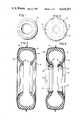
- FIG. 10is a cross-sectional view of a rubber ring showing its configuration
- FIG. 11is similar to FIG. 10 showing a metal band in position with the rubber ring when assembled;
- FIG. 12is a side view of a metal band without the locking mechanism or the rubber ring;
- FIG. 13is a perspective view of the bead seal ring unit assembly with the rubber ring and the locking mechanism in place;
- FIG. 14is an exploded perspective view of the locking mechanism in conjunction with the metal band
- FIG. 15is a side sectional view of the locking mechanism in the locked or expanded position.
- FIG. 16is a side sectional view of a locking mechanism in the unlocked or retracted position.
- FIG. 1there is illustrated a radial tire generally by number 10. After the radial tire has been prepared for retreading, it is covered with a curing envelope 12, as shown in FIG. 2. This is typical for many retreading operations with the possible exception that the curing envelope is more fully skirted or extends further toward the center of the tire.
- the crown area 14connects the bead areas 16 and 18 by sidewall sections 19 and 20.
- the curing envelope 12extends around the tire 10 and past the bead areas 16 and 18.
- bead seal ring unit assemblies 24have been placed in sealing position and were expanded mechanically in the radial direction to make positive sealing contacts with the bead areas 16 and 18. This view illustrates the principles of the present invention.
- FIG. 13shows the bead seal ring unit assembly 24 in partial cross-section showing the rubber ring 26 positioned around the metal band 27.
- Metal band 27, as shown in FIG. 2has overlapping ends to complete its circular embodiment. The inside end is identified as 28 and the outside end is identified as 29.
- the locking mechanism 30is connected to the outside end 29 and the inside 28. The locking mechanism 30 is so constructed that the metal band 27 will be in its small diameter position when the locking mechanism 30 is in the unlocked position and in the expanded position when the locking mechanism 30 is in the locked position. This will be explained in detail below.
- the envelope 12extends alongside of the bead area and out of contact with it before the bead seal ring unit assemblies 24 are placed in sealing position.
- the curing envelope 12is flexible but exhibits a stiff characteristic before being moved into sealing position.
- FIG. 10we have a cross-sectional view of the rubber ring 26.
- the rubber ringhas a position flange 38 and a hook flange 40.
- the flanges 38 and 40are connected by sealing surface 42 at their upper side.
- the sealing surfacein the preferred embodiment, as shown in FIG. 10, has a series of sealing ribs 44.
- the flanges 38 and 40are connected by a receiving groove 46.
- the receiving groove 46has slanted side surfaces 47 so that they can receive the metal band 27 and hold it in place, as illustrated in FIG. 11.
- the rubber ring 26When the rubber ring 26 is moved into sealing position, it will contact the curing envelope 12 and move it between the axial bead surface 34 and the sealing surface 42 of the rubber ring 26, as illustrated in FIG. 6. At this time, the locking mechanism 30 is in the unlocked position and the metal band is in its smallest diameter position.
- the rubber ring 26has a diameter smaller than the bead area diameter so that sealing contact is not made at this time.
- the locking mechanism 30is moved to the locked position, by expanding the diameter of the rubber ring 26 so that the curing envelope is sealed between the axial bead surface 34 and the sealing surface 42 of the rubber ring 26.
- the sealing ribsprovide multiple gripping contacts so that curing envelope is firmly held in place.
- the bead area 16is rigid and a sufficient amount of pressure can be placed between the bead seal ring unit assembly 24, in the expanded position, and the bead member 16 so that the curing envelope 12 is securely sealed.
- FIG. 8illustrates a radial tire after it has been enveloped and sealed and is ready to be placed into a curing chamber.
- the axial bead surface 34is at a slight angle in reference to the axis of the tire. Typical angles would be 15°-19°.
- the hook flange 40will wrap the end of the curing envelope 12 past the inside of the bead toe 32, as seen in FIG. 6.
- the hook 40prevents the rubber ring 26 from moving out past the bead toe 32 when in the expanded condition.
- the positioning flange 38prevents the bead seal ring unit assembly 24 from extending past the bead side surface 36.
- the metal band 27 and the rubber ring 26are positioned together to form the bead seal ring unit assembly. After a period of time, the rubber ring can lose its resilience, thus affecting its sealing capabilities, and will have to be replaced. The replacement is easily made by putting the metal band 27 in the unlocked position and removing the rubber ring 26 from the metal band. The resiliency of the rubber ring 26 can be monitored visually by the locking mechanism as will be explained in more detail below.
- the locking mechanism 30is connected to and operates the metal band 27.
- the locking mechanism 30has four major elements. These include a band bracket 48, a slide bracket 50, a spring assembly 52, and a handle bracket 54.
- the band bracket 48has two side plates 62 connected to a securing plate 61 and provides the connection to the inside end 28 of the metal band 27 for the locking mechanism 30. Near the back of the side plates 62, there are provided holes to receive a guide pin 64 and a spring pin 66. The bracket 48 is secured to the inside end 28 of the metal band 27 by connecting rivets 68.
- Slide bracket 50has two slide plates 72 connected to support plate 71.
- the slide plates 72are provided with undercuts 74, the function of which will be explained later.
- the side slide plates 72are provided with guide slots 75.
- the guide pin 64 and spring pin 66pass through the guide slots 75.
- the slide plates 72 at their front end,are provided with openings to receive pivot pin 76, which extend across the support plate 71 and are secured in the slide plates 72.
- the slide bracket 50is secured to the outside end 29 of the metal band 27 by connecting rivots 78.
- the side slide plates 72are positioned outside the side plates 62 of the band bracket 48 when the unit is assembled.
- the undercuts 74permit the slide bracket 50 to be moved in relation to the band bracket 48 without making contact with the inside end 28 of metal band 27 until in the fully unlocked position.
- Spring assembly 52has a spring shaft member 81 with a yoke member 82 positioned on one end.
- the yoke member 81has a yoke plate 84 that is connected to the shaft member 81 and connects to two side members 86.
- the two side members 86have openings which receive the spring pin 66.
- On the other end of the shaft member 81is a pivot block 88.
- the pivot block 88has an opening permitting the shaft 81 to pass through the pivot block 88 and a control cap 90 is secured to the end of the shaft 81.
- On the side of the pivot block 88are pivot studs 92.
- a spring 94is positioned around the shaft 81 and applies force to the yoke plate 84 and to the pivot block 88. When under normal conditions, the spring will exert pressure between these members causing the control cap 90 to make contact with the pivot block 88.
- the handle bracket 104has side plates 101 that are connected by connection plate 102.
- a handle arm 104is secured to the connection plate 102 at one end and has a handle 105 at the other end.
- the handle armAbove the connection plate 102, the handle arm has a control edge 107.
- the side plates 101have control flanges 108 extending up from the side plates.
- the side plates 101have openings identified as pivot stud openings 111 which receive the pivot studs 92. Near the front end of the side plates 101 are provided openings which permit the pivot pin 76 to pass through.
- FIG. 16we show the locking mechanism in the relaxed or unlocked position.
- the inside end 28 and the outside end 29 of the metal band 27are overlapped at their maximum amount when the handle is fully moved into the unlocked position.
- Thisis a condition in which the locking mechanism 30 is in when the bead seal ring unit assembly 24 is placed into sealing position. Sealing contact is then secured by moving the handle in a counter-clockwise direction, as viewed in FIGS. 15 and 16, to its maximum locked position as illustrated in FIG. 15.
- the handle bracket 54is rotated about the pivot pin 76. This moves the pivot block 88 so that it tends to compress spring 94.
- FIG. 8shows the tire 10 after it has been prepared for retreading and the curing envelope 12 placed on the tire 10 and the bead seal ring unit assemblies 24 positioned in sealing contact with the bead member of the radial tire 10 and the curing envelope 12.
- the locking mechanisms 30are lined up with one another. This is not a precise line-up, but should be as close as an operator can easily position them.
- the tire 10After the tire 10 is in this condition, it is ready to be cured. At this time, the tire 10 will be supported by a chain hanger 120.
- the chain hanger 120is connected to a monorail system well-known in the art by the monorail rollers. Connecting rods hang down from the monorail rollers to a carrier member.
- support chains 122are suspended and then connected to a support member 124.
- the support member 124will act on the locking mechanism 30 between the control edge 107 and the control flanges 108. They will support the tire assembly on the upper edges of the side slide plates 72.
- the chain hanger 120will provide support during the curing without causing any damage to the curing envelope 12 and the bead sealing units.
- This systemmaintains a constant pressure by means of the spring assembly in the locking mechanism 30.
- Thisalso provides a system to accommodate variations in tire constructions by various tire manufacturers.
- the systemprovides a mechanism that is lightweight, easily handled by one individual, and reduces the time of placement and removal of the sealing devices while providing positive, effective sealing features.
- outer embodimentscould be employed.
- FIG. 13we illustrate a smooth surface which would also be utilized in this type of sealing.
- the sealing ribsare preferred in our embodiment because they allow better sealing and gripping of the curing envelope. While the preferred embodiments of the sealing system have been shown and described here and in detail, those skilled in the art will recognize various alternative design embodiments for practicing the present invention as defined by the following claims.
Landscapes
- Mechanical Engineering (AREA)
- Engineering & Computer Science (AREA)
- Control Of Eletrric Generators (AREA)
- Joints Allowing Movement (AREA)
- Sealing Devices (AREA)
- Tires In General (AREA)
- Tyre Moulding (AREA)
- Seal Device For Vehicle (AREA)
- Moulds For Moulding Plastics Or The Like (AREA)
- Heating, Cooling, Or Curing Plastics Or The Like In General (AREA)
- Rolling Contact Bearings (AREA)
- Separation, Recovery Or Treatment Of Waste Materials Containing Plastics (AREA)
- Saccharide Compounds (AREA)
- Sealing Material Composition (AREA)
- Soil Working Implements (AREA)
- Catching Or Destruction (AREA)
- Breeding Of Plants And Reproduction By Means Of Culturing (AREA)
- Pivots And Pivotal Connections (AREA)
- Gasket Seals (AREA)
Abstract
Description
Claims (11)
Priority Applications (18)
| Application Number | Priority Date | Filing Date | Title |
|---|---|---|---|
| US06/796,458US4634357A (en) | 1985-11-08 | 1985-11-08 | Bead seal ring unit |
| IN834/DEL/86AIN166728B (en) | 1985-11-08 | 1986-09-22 | |
| PH34285APH23291A (en) | 1985-11-08 | 1986-09-24 | Bead seal ring unit |
| EP86113516AEP0218185B1 (en) | 1985-10-08 | 1986-10-01 | Bead seal ring unit |
| AT86113516TATE72171T1 (en) | 1985-11-08 | 1986-10-01 | SEALING RING FOR TIRE BEAD. |
| DE8686113516TDE3683717D1 (en) | 1985-11-08 | 1986-10-01 | SEALING RING FOR TIRE BEADS. |
| ES86113516TES2029989T3 (en) | 1985-11-08 | 1986-10-01 | GLOBULAR SEALING UNIT WITH WASHER |
| AU63577/86AAU580939B2 (en) | 1985-11-08 | 1986-10-02 | Bead seal ring unit |
| NZ217810ANZ217810A (en) | 1985-11-08 | 1986-10-06 | Expanding ring for holding radial tyre tread curing envelope against tyre bead |
| MX4006AMX160872A (en) | 1985-11-08 | 1986-10-10 | IMPROVEMENTS IN APPARATUS AND METHOD FOR RETREADING RADIAL TIRES |
| ZA868208AZA868208B (en) | 1985-11-08 | 1986-10-28 | Bead seal ring unit |
| NO864385ANO864385L (en) | 1985-11-08 | 1986-11-03 | APPARATUS FOR SEATING RING AND PROCEDURE FOR REGUMPING RADIAL TIRES USING SUCH SEATING RING. |
| FI864520AFI87905C (en) | 1985-11-08 | 1986-11-06 | Sealing ring assembly for use in retreading of belt tires and method of retreading of belt tires using this assembly |
| CA000522315ACA1294098C (en) | 1985-11-08 | 1986-11-06 | Bead seal ring unit |
| DK532686ADK165943C (en) | 1985-11-08 | 1986-11-07 | SPREADING UNIT FOR SEALING THE TIRES ON A RADIAL COVER, WHICH VOLCANIZES A TREAD |
| JP61265427AJPH0661877B2 (en) | 1985-11-08 | 1986-11-07 | Radial tread regeneration method and bead seal ring unit used in this method |
| BR8605526ABR8605526A (en) | 1985-11-08 | 1986-11-07 | TALON SEALING RING UNIT SET AND PROCESS OF RETREADING A RADIAL TIRE HOUSING |
| GR920400521TGR3004159T3 (en) | 1985-11-08 | 1992-03-26 |
Applications Claiming Priority (1)
| Application Number | Priority Date | Filing Date | Title |
|---|---|---|---|
| US06/796,458US4634357A (en) | 1985-11-08 | 1985-11-08 | Bead seal ring unit |
Publications (1)
| Publication Number | Publication Date |
|---|---|
| US4634357Atrue US4634357A (en) | 1987-01-06 |
Family
ID=25168233
Family Applications (1)
| Application Number | Title | Priority Date | Filing Date |
|---|---|---|---|
| US06/796,458Expired - LifetimeUS4634357A (en) | 1985-10-08 | 1985-11-08 | Bead seal ring unit |
Country Status (18)
| Country | Link |
|---|---|
| US (1) | US4634357A (en) |
| EP (1) | EP0218185B1 (en) |
| JP (1) | JPH0661877B2 (en) |
| AT (1) | ATE72171T1 (en) |
| AU (1) | AU580939B2 (en) |
| BR (1) | BR8605526A (en) |
| CA (1) | CA1294098C (en) |
| DE (1) | DE3683717D1 (en) |
| DK (1) | DK165943C (en) |
| ES (1) | ES2029989T3 (en) |
| FI (1) | FI87905C (en) |
| GR (1) | GR3004159T3 (en) |
| IN (1) | IN166728B (en) |
| MX (1) | MX160872A (en) |
| NO (1) | NO864385L (en) |
| NZ (1) | NZ217810A (en) |
| PH (1) | PH23291A (en) |
| ZA (1) | ZA868208B (en) |
Cited By (10)
| Publication number | Priority date | Publication date | Assignee | Title |
|---|---|---|---|---|
| US4861247A (en)* | 1986-08-23 | 1989-08-29 | Karl Schimanek | Expandable ring for sealing an envelope against the bead of a tire to be retreaded |
| US5098509A (en)* | 1991-05-13 | 1992-03-24 | Leslie Bubik | Tire envelope sealing device |
| DE4229125A1 (en)* | 1992-09-01 | 1994-03-03 | Karl Schimanek | Cover sealing ring - clamps cover on bulge inner surface of renewable tyre and thereby seals it |
| US5518384A (en)* | 1994-08-10 | 1996-05-21 | Presti; Barry W. | Radially expandable and retractable rim |
| US6406282B1 (en)* | 1999-03-03 | 2002-06-18 | Presti Rubber Products, Inc. | Sealing ring and rim assembly for use in retreading tires |
| US20030096031A1 (en)* | 2001-11-19 | 2003-05-22 | Presti Barry W. | Two-piece retread envelope |
| US20100012256A1 (en)* | 2006-11-29 | 2010-01-21 | Bridgestone Corporation | Method of producing retreaded tire |
| JP2013233731A (en)* | 2012-05-09 | 2013-11-21 | Bridgestone Corp | Vulcanization envelope |
| US8701238B1 (en)* | 2013-09-18 | 2014-04-22 | Worldwide Integrated Resources, Inc. | Hand operated sweeping mop with shotgun mechanism to release a used cleaning cloth |
| US20150321432A1 (en)* | 2008-04-18 | 2015-11-12 | Pirelli Tyre S.P.A | Process and apparatus for assembling tyres |
Families Citing this family (4)
| Publication number | Priority date | Publication date | Assignee | Title |
|---|---|---|---|---|
| US4850834A (en)* | 1987-12-30 | 1989-07-25 | The Hercules Tire And Rubber Company | Retread ring |
| US4808256A (en)* | 1988-03-03 | 1989-02-28 | Oliver Rubber Company | Tire recapping apparatus |
| US8136378B2 (en) | 2009-09-21 | 2012-03-20 | Ford Global Technologies, Llc | Seal for fluid forming tools |
| IT201700084375A1 (en)* | 2017-07-25 | 2019-01-25 | Pirelli | Apparatus for packaging a tire for vehicle wheels |
Citations (16)
| Publication number | Priority date | Publication date | Assignee | Title |
|---|---|---|---|---|
| US1940582A (en)* | 1930-01-14 | 1933-12-19 | Nat Rubber Machinery Co | Vulcanizing press |
| US2475579A (en)* | 1947-12-05 | 1949-07-05 | Clement O Dennis | Tire recapping apparatus |
| CA522114A (en)* | 1956-02-28 | Zangl Karl | Tire vulcanizing press | |
| US2966936A (en)* | 1955-07-26 | 1961-01-03 | Schelkmann Wilhelm | Working method for recapping and repairing tires |
| US3184794A (en)* | 1961-07-13 | 1965-05-25 | Morris A Sherkin | Sealing apparatus for tires |
| US3236709A (en)* | 1962-10-04 | 1966-02-22 | Bandag Inc | Tire recapping process |
| US3802978A (en)* | 1972-02-07 | 1974-04-09 | Brad Ragan Inc | Method and apparatus for tire tread bonding |
| US3884740A (en)* | 1973-09-20 | 1975-05-20 | Wilhelm Schelkmann | Method of retreading tires |
| US3895985A (en)* | 1972-04-11 | 1975-07-22 | Wilhelm Schelkmann | Method of repairing tires and shells used for this method |
| US3966535A (en)* | 1975-01-15 | 1976-06-29 | Antonio Dabura Abularach | Envelope sealing apparatus for cold process tire retreading |
| US4129474A (en)* | 1976-02-27 | 1978-12-12 | Republic Rubber Industries (Prop.) Ltd. | Retreading of tires |
| US4175991A (en)* | 1977-11-14 | 1979-11-27 | Harrelson Rubber Company | Tire retreading method |
| GB2032858A (en)* | 1978-10-04 | 1980-05-14 | Michelin & Cie | The Retreading or Repairing of Pneumatic Tyres for Vehicle Wheels |
| US4242169A (en)* | 1979-10-11 | 1980-12-30 | Harrelson Rubber Company | Tire retreading apparatus |
| US4274897A (en)* | 1979-07-13 | 1981-06-23 | Barefoot Carlton K | Method and apparatus for vulcanizing tires |
| US4309234A (en)* | 1980-06-23 | 1982-01-05 | Long Mile Rubber Company | Tire retreading envelope seal |
Family Cites Families (3)
| Publication number | Priority date | Publication date | Assignee | Title |
|---|---|---|---|---|
| FR2319483A1 (en)* | 1975-08-01 | 1977-02-25 | Michelin & Cie | DEVICE FOR RETREADING OF TIRES |
| IN162363B (en)* | 1984-02-13 | 1988-05-14 | Oliver Rubber Co | |
| ATE47087T1 (en)* | 1986-08-23 | 1989-10-15 | Vv System Ag | EXPANDABLE RING FOR SEALING A SLEEVE ON THE BEAD OF A TIRE TO BE REPLACED. |
- 1985
- 1985-11-08USUS06/796,458patent/US4634357A/ennot_activeExpired - Lifetime
- 1986
- 1986-09-22ININ834/DEL/86Apatent/IN166728B/enunknown
- 1986-09-24PHPH34285Apatent/PH23291A/enunknown
- 1986-10-01ATAT86113516Tpatent/ATE72171T1/ennot_activeIP Right Cessation
- 1986-10-01EPEP86113516Apatent/EP0218185B1/ennot_activeExpired - Lifetime
- 1986-10-01ESES86113516Tpatent/ES2029989T3/ennot_activeExpired - Lifetime
- 1986-10-01DEDE8686113516Tpatent/DE3683717D1/ennot_activeExpired - Lifetime
- 1986-10-02AUAU63577/86Apatent/AU580939B2/ennot_activeExpired
- 1986-10-06NZNZ217810Apatent/NZ217810A/enunknown
- 1986-10-10MXMX4006Apatent/MX160872A/enunknown
- 1986-10-28ZAZA868208Apatent/ZA868208B/enunknown
- 1986-11-03NONO864385Apatent/NO864385L/enunknown
- 1986-11-06CACA000522315Apatent/CA1294098C/ennot_activeExpired - Lifetime
- 1986-11-06FIFI864520Apatent/FI87905C/ennot_activeIP Right Cessation
- 1986-11-07BRBR8605526Apatent/BR8605526A/ennot_activeIP Right Cessation
- 1986-11-07DKDK532686Apatent/DK165943C/ennot_activeIP Right Cessation
- 1986-11-07JPJP61265427Apatent/JPH0661877B2/ennot_activeExpired - Fee Related
- 1992
- 1992-03-26GRGR920400521Tpatent/GR3004159T3/elunknown
Patent Citations (16)
| Publication number | Priority date | Publication date | Assignee | Title |
|---|---|---|---|---|
| CA522114A (en)* | 1956-02-28 | Zangl Karl | Tire vulcanizing press | |
| US1940582A (en)* | 1930-01-14 | 1933-12-19 | Nat Rubber Machinery Co | Vulcanizing press |
| US2475579A (en)* | 1947-12-05 | 1949-07-05 | Clement O Dennis | Tire recapping apparatus |
| US2966936A (en)* | 1955-07-26 | 1961-01-03 | Schelkmann Wilhelm | Working method for recapping and repairing tires |
| US3184794A (en)* | 1961-07-13 | 1965-05-25 | Morris A Sherkin | Sealing apparatus for tires |
| US3236709A (en)* | 1962-10-04 | 1966-02-22 | Bandag Inc | Tire recapping process |
| US3802978A (en)* | 1972-02-07 | 1974-04-09 | Brad Ragan Inc | Method and apparatus for tire tread bonding |
| US3895985A (en)* | 1972-04-11 | 1975-07-22 | Wilhelm Schelkmann | Method of repairing tires and shells used for this method |
| US3884740A (en)* | 1973-09-20 | 1975-05-20 | Wilhelm Schelkmann | Method of retreading tires |
| US3966535A (en)* | 1975-01-15 | 1976-06-29 | Antonio Dabura Abularach | Envelope sealing apparatus for cold process tire retreading |
| US4129474A (en)* | 1976-02-27 | 1978-12-12 | Republic Rubber Industries (Prop.) Ltd. | Retreading of tires |
| US4175991A (en)* | 1977-11-14 | 1979-11-27 | Harrelson Rubber Company | Tire retreading method |
| GB2032858A (en)* | 1978-10-04 | 1980-05-14 | Michelin & Cie | The Retreading or Repairing of Pneumatic Tyres for Vehicle Wheels |
| US4274897A (en)* | 1979-07-13 | 1981-06-23 | Barefoot Carlton K | Method and apparatus for vulcanizing tires |
| US4242169A (en)* | 1979-10-11 | 1980-12-30 | Harrelson Rubber Company | Tire retreading apparatus |
| US4309234A (en)* | 1980-06-23 | 1982-01-05 | Long Mile Rubber Company | Tire retreading envelope seal |
Cited By (14)
| Publication number | Priority date | Publication date | Assignee | Title |
|---|---|---|---|---|
| US4861247A (en)* | 1986-08-23 | 1989-08-29 | Karl Schimanek | Expandable ring for sealing an envelope against the bead of a tire to be retreaded |
| US5098509A (en)* | 1991-05-13 | 1992-03-24 | Leslie Bubik | Tire envelope sealing device |
| DE4229125A1 (en)* | 1992-09-01 | 1994-03-03 | Karl Schimanek | Cover sealing ring - clamps cover on bulge inner surface of renewable tyre and thereby seals it |
| US5518384A (en)* | 1994-08-10 | 1996-05-21 | Presti; Barry W. | Radially expandable and retractable rim |
| US6406282B1 (en)* | 1999-03-03 | 2002-06-18 | Presti Rubber Products, Inc. | Sealing ring and rim assembly for use in retreading tires |
| US6783343B2 (en) | 2001-11-19 | 2004-08-31 | Tripoint Llc | Two-piece retread envelope |
| US20030096031A1 (en)* | 2001-11-19 | 2003-05-22 | Presti Barry W. | Two-piece retread envelope |
| US20100012256A1 (en)* | 2006-11-29 | 2010-01-21 | Bridgestone Corporation | Method of producing retreaded tire |
| US20150321432A1 (en)* | 2008-04-18 | 2015-11-12 | Pirelli Tyre S.P.A | Process and apparatus for assembling tyres |
| US10065382B2 (en)* | 2008-04-18 | 2018-09-04 | Pirelli Tyre S.P.A. | Process and apparatus for assembling tyres |
| US10377101B2 (en)* | 2008-04-18 | 2019-08-13 | Pirelli Tyre S.P.A. | Process and apparatus for assembling types |
| JP2013233731A (en)* | 2012-05-09 | 2013-11-21 | Bridgestone Corp | Vulcanization envelope |
| US8701238B1 (en)* | 2013-09-18 | 2014-04-22 | Worldwide Integrated Resources, Inc. | Hand operated sweeping mop with shotgun mechanism to release a used cleaning cloth |
| US9113772B1 (en)* | 2013-09-18 | 2015-08-25 | Worldwide Integrated Resources, Inc. | Hand operated sweeping mop with shotgun mechanism to release a used cleaning cloth |
Also Published As
| Publication number | Publication date |
|---|---|
| EP0218185A2 (en) | 1987-04-15 |
| NO864385D0 (en) | 1986-11-03 |
| IN166728B (en) | 1990-07-14 |
| ES2029989T3 (en) | 1992-10-16 |
| DK165943B (en) | 1993-02-15 |
| JPS62216737A (en) | 1987-09-24 |
| FI864520A0 (en) | 1986-11-06 |
| DK532686A (en) | 1987-05-09 |
| JPH0661877B2 (en) | 1994-08-17 |
| FI87905C (en) | 1993-03-10 |
| EP0218185B1 (en) | 1992-01-29 |
| EP0218185A3 (en) | 1988-10-12 |
| MX160872A (en) | 1990-06-07 |
| FI864520L (en) | 1987-05-09 |
| CA1294098C (en) | 1992-01-14 |
| AU580939B2 (en) | 1989-02-02 |
| PH23291A (en) | 1989-06-30 |
| AU6357786A (en) | 1987-05-14 |
| BR8605526A (en) | 1987-08-11 |
| ZA868208B (en) | 1987-06-24 |
| NO864385L (en) | 1987-05-11 |
| GR3004159T3 (en) | 1993-03-31 |
| ATE72171T1 (en) | 1992-02-15 |
| DK532686D0 (en) | 1986-11-07 |
| NZ217810A (en) | 1988-11-29 |
| DK165943C (en) | 1993-07-05 |
| DE3683717D1 (en) | 1992-03-12 |
| FI87905B (en) | 1992-11-30 |
Similar Documents
| Publication | Publication Date | Title |
|---|---|---|
| US4634357A (en) | Bead seal ring unit | |
| US3886028A (en) | Apparatus for recapping tires with precured tread rubber | |
| US4309234A (en) | Tire retreading envelope seal | |
| US3614969A (en) | Tire recapping rim | |
| US4401144A (en) | Wheel rims for pneumatic tires | |
| US4169496A (en) | Run-flat tire and wheel arrangement with inverted bead interlock | |
| AU592563B2 (en) | Method and apparatus for recapping a tire with a flexible segmented mold | |
| US4929298A (en) | Tire building drum including an expandable segmental cylinder assembly and a vacuum chamber | |
| FI83608B (en) | RELEASE FOER RINGMANTEL FOER YTBELAEGGNING AV RINGAR. | |
| US4148680A (en) | Tire building machine | |
| US2381382A (en) | Bead lock | |
| US5518384A (en) | Radially expandable and retractable rim | |
| PT79180B (en) | Method and tire envelope sealing apparatus for recapping same | |
| US2443955A (en) | Device for use in retreading and vulcanizing pneumatic tires | |
| EP0397735B1 (en) | Retread ring | |
| US3329192A (en) | Airless tire | |
| KR910009357A (en) | Metal-Elastomer Synthetic Wheel Forming Equipment | |
| AU688621B2 (en) | Apparatus for manufacturing recapped tire | |
| US4105254A (en) | Wheel with rim embraced by tire | |
| US6406282B1 (en) | Sealing ring and rim assembly for use in retreading tires | |
| US5098509A (en) | Tire envelope sealing device | |
| EP0359388A2 (en) | An emergency support ring for a pneumatic tyre and wheel rim assembly | |
| US3216062A (en) | Sealing diaphragm for tires | |
| US4662834A (en) | Hub replacement device for tire retreading apparatus | |
| CA1046108A (en) | Pneumatic tyre and wheel assemblies |
Legal Events
| Date | Code | Title | Description |
|---|---|---|---|
| AS | Assignment | Owner name:BANDAG LICENSING CORPORATION BANDAG CENTER, MUSCAT Free format text:ASSIGNMENT OF ASSIGNORS INTEREST.;ASSIGNORS:BREWER, DONALDEE;SEILER, RONALD R.;NIEDERGESES, THOMAS J.;REEL/FRAME:004561/0803 Effective date:19860428 Owner name:BANDAG LICENSING CORPORATION, IOWA Free format text:ASSIGNMENT OF ASSIGNORS INTEREST;ASSIGNORS:BREWER, DONALDEE;SEILER, RONALD R.;NIEDERGESES, THOMAS J.;REEL/FRAME:004561/0803 Effective date:19860428 | |
| STCF | Information on status: patent grant | Free format text:PATENTED CASE | |
| FPAY | Fee payment | Year of fee payment:4 | |
| FEPP | Fee payment procedure | Free format text:PAYOR NUMBER ASSIGNED (ORIGINAL EVENT CODE: ASPN); ENTITY STATUS OF PATENT OWNER: LARGE ENTITY | |
| FPAY | Fee payment | Year of fee payment:8 | |
| FPAY | Fee payment | Year of fee payment:12 | |
| AS | Assignment | Owner name:BANDAG, INCORPORATED, IOWA Free format text:MERGER;ASSIGNOR:BANDAG LICENSING CORPORATION;REEL/FRAME:016263/0547 Effective date:20041110 |