US4634229A - Liquid crystal display - Google Patents
Liquid crystal displayDownload PDFInfo
- Publication number
- US4634229A US4634229AUS06/626,380US62638084AUS4634229AUS 4634229 AUS4634229 AUS 4634229AUS 62638084 AUS62638084 AUS 62638084AUS 4634229 AUS4634229 AUS 4634229A
- Authority
- US
- United States
- Prior art keywords
- liquid crystal
- angle
- crystal display
- orientation
- display
- Prior art date
- Legal status (The legal status is an assumption and is not a legal conclusion. Google has not performed a legal analysis and makes no representation as to the accuracy of the status listed.)
- Expired - Lifetime
Links
- 239000004973liquid crystal related substanceSubstances0.000titleclaimsabstractdescription77
- 125000006850spacer groupChemical group0.000claimsabstractdescription6
- 239000000654additiveSubstances0.000claimsdescription9
- 230000000996additive effectEffects0.000claimsdescription9
- 230000003287optical effectEffects0.000claimsdescription8
- 239000004988Nematic liquid crystalSubstances0.000claimsdescription6
- 230000001747exhibiting effectEffects0.000claims3
- 238000000034methodMethods0.000abstractdescription6
- 230000000694effectsEffects0.000abstractdescription4
- 238000005286illuminationMethods0.000abstractdescription2
- 239000011521glassSubstances0.000description5
- 239000000203mixtureSubstances0.000description4
- 230000005540biological transmissionEffects0.000description3
- WCLNGBQPTVENHV-MKQVXYPISA-Ncholesteryl nonanoateChemical compoundC([C@@H]12)C[C@]3(C)[C@@H]([C@H](C)CCCC(C)C)CC[C@H]3[C@@H]1CC=C1[C@]2(C)CC[C@H](OC(=O)CCCCCCCC)C1WCLNGBQPTVENHV-MKQVXYPISA-N0.000description3
- 239000011159matrix materialSubstances0.000description3
- 238000001771vacuum depositionMethods0.000description3
- 238000005259measurementMethods0.000description2
- WLPATYNQCGVFFH-UHFFFAOYSA-N2-phenylbenzonitrileChemical groupN#CC1=CC=CC=C1C1=CC=CC=C1WLPATYNQCGVFFH-UHFFFAOYSA-N0.000description1
- 239000013078crystalSubstances0.000description1
- 230000003247decreasing effectEffects0.000description1
- 230000008034disappearanceEffects0.000description1
- 239000000428dustSubstances0.000description1
- 230000005684electric fieldEffects0.000description1
- 238000005516engineering processMethods0.000description1
- 229920006333epoxy cementPolymers0.000description1
- 239000003365glass fiberSubstances0.000description1
- 238000012986modificationMethods0.000description1
- 230000004048modificationEffects0.000description1
- 239000002245particleSubstances0.000description1
- 229920000642polymerPolymers0.000description1
- 230000035945sensitivityEffects0.000description1
- 238000000926separation methodMethods0.000description1
- 230000003595spectral effectEffects0.000description1
Images


Classifications
- G—PHYSICS
- G02—OPTICS
- G02F—OPTICAL DEVICES OR ARRANGEMENTS FOR THE CONTROL OF LIGHT BY MODIFICATION OF THE OPTICAL PROPERTIES OF THE MEDIA OF THE ELEMENTS INVOLVED THEREIN; NON-LINEAR OPTICS; FREQUENCY-CHANGING OF LIGHT; OPTICAL LOGIC ELEMENTS; OPTICAL ANALOGUE/DIGITAL CONVERTERS
- G02F1/00—Devices or arrangements for the control of the intensity, colour, phase, polarisation or direction of light arriving from an independent light source, e.g. switching, gating or modulating; Non-linear optics
- G02F1/01—Devices or arrangements for the control of the intensity, colour, phase, polarisation or direction of light arriving from an independent light source, e.g. switching, gating or modulating; Non-linear optics for the control of the intensity, phase, polarisation or colour
- G02F1/17—Devices or arrangements for the control of the intensity, colour, phase, polarisation or direction of light arriving from an independent light source, e.g. switching, gating or modulating; Non-linear optics for the control of the intensity, phase, polarisation or colour based on variable-absorption elements not provided for in groups G02F1/015 - G02F1/169
- G—PHYSICS
- G02—OPTICS
- G02F—OPTICAL DEVICES OR ARRANGEMENTS FOR THE CONTROL OF LIGHT BY MODIFICATION OF THE OPTICAL PROPERTIES OF THE MEDIA OF THE ELEMENTS INVOLVED THEREIN; NON-LINEAR OPTICS; FREQUENCY-CHANGING OF LIGHT; OPTICAL LOGIC ELEMENTS; OPTICAL ANALOGUE/DIGITAL CONVERTERS
- G02F1/00—Devices or arrangements for the control of the intensity, colour, phase, polarisation or direction of light arriving from an independent light source, e.g. switching, gating or modulating; Non-linear optics
- G02F1/01—Devices or arrangements for the control of the intensity, colour, phase, polarisation or direction of light arriving from an independent light source, e.g. switching, gating or modulating; Non-linear optics for the control of the intensity, phase, polarisation or colour
- G02F1/13—Devices or arrangements for the control of the intensity, colour, phase, polarisation or direction of light arriving from an independent light source, e.g. switching, gating or modulating; Non-linear optics for the control of the intensity, phase, polarisation or colour based on liquid crystals, e.g. single liquid crystal display cells
- G02F1/137—Devices or arrangements for the control of the intensity, colour, phase, polarisation or direction of light arriving from an independent light source, e.g. switching, gating or modulating; Non-linear optics for the control of the intensity, phase, polarisation or colour based on liquid crystals, e.g. single liquid crystal display cells characterised by the electro-optical or magneto-optical effect, e.g. field-induced phase transition, orientation effect, guest-host interaction or dynamic scattering
- G02F1/139—Devices or arrangements for the control of the intensity, colour, phase, polarisation or direction of light arriving from an independent light source, e.g. switching, gating or modulating; Non-linear optics for the control of the intensity, phase, polarisation or colour based on liquid crystals, e.g. single liquid crystal display cells characterised by the electro-optical or magneto-optical effect, e.g. field-induced phase transition, orientation effect, guest-host interaction or dynamic scattering based on orientation effects in which the liquid crystal remains transparent
- G02F1/1396—Devices or arrangements for the control of the intensity, colour, phase, polarisation or direction of light arriving from an independent light source, e.g. switching, gating or modulating; Non-linear optics for the control of the intensity, phase, polarisation or colour based on liquid crystals, e.g. single liquid crystal display cells characterised by the electro-optical or magneto-optical effect, e.g. field-induced phase transition, orientation effect, guest-host interaction or dynamic scattering based on orientation effects in which the liquid crystal remains transparent the liquid crystal being selectively controlled between a twisted state and a non-twisted state, e.g. TN-LC cell
- G02F1/1397—Devices or arrangements for the control of the intensity, colour, phase, polarisation or direction of light arriving from an independent light source, e.g. switching, gating or modulating; Non-linear optics for the control of the intensity, phase, polarisation or colour based on liquid crystals, e.g. single liquid crystal display cells characterised by the electro-optical or magneto-optical effect, e.g. field-induced phase transition, orientation effect, guest-host interaction or dynamic scattering based on orientation effects in which the liquid crystal remains transparent the liquid crystal being selectively controlled between a twisted state and a non-twisted state, e.g. TN-LC cell the twist being substantially higher than 90°, e.g. STN-, SBE-, OMI-LC cells
Definitions
- This inventionrelates to a liquid crystal display of the type known, e.g. from J. Appl. Phys., Vol. 53, No. 12 (December 1982), pages 8599 to 8606.
- This liquid crystal display described in the above-noted referencefunctions according to the bistability effect and consists of a cell with two plane-parallel glass plates separated by means of spacers at the border of the cell and bonded together on only two sides. The distance between the glass plates is about 15 ⁇ m. It is expressly mentioned that dust particles in the cell and disturbances on the surface of the glass plates are unfavorable for such a display. These phenomena accelerate the disappearance of the displayed information, which is unavoidable with these driving methods. The display must therefore be constantly refreshed.
- the display cellis located between two crossed polarizers. Electrode layers and orientation layers formed over the electrode layers are provided on the inner surfaces of the glass plates.
- the orientation layersare produced by oblique vacuum deposition of SiO at a 5° angle to the plate plane. As a result, the adjoining liquid crystal molecules are aligned with a tilt angle of 55° perpendicular to the plate.
- the directions of orientation of the orientation layersare either parallel or perpendicular to the transmission axes of the polarizers.
- a cyanobiphenyl mixture E7 with the chiral additive cholesteryl nonanoateis filled into the cell as the liquid crystal.
- the internal twist angle of the liquid crystalis 360°; the ratio between layer thickness and pitch is 0.983.
- a range of from 0.95 to 1.10is regarded as appropriate for this ratio. Below 0.95, the switching times are very long, so that this range is to be excluded for such a display. Moreover, the aim is for flawless bistable action of the display, for which layer thickness and pitch ought to be about the same.
- the displayis driven either according to the 3:1 addressing scheme or according to the 2:1 addressing scheme in both of which the writing is done line-at-a-time. Since the display must be constantly refreshed, only a few lines can be written. This means that the degree of multiplexing is low and that a dot matrix display with a large number of lines is not achievable according to the above reference.
- the objects of this inventionare to provide a novel liquid crystal display based on the bistability effect, which makes possible a steady display without refreshing, which can be driven according to the usual multiplexing technique with a high degree of multiplexing and which possesses a wide range of viewing angles with a high contrast.
- a liquid crystal display according to the inventionwhich is based on the knowledge that the voltage range over which bistable behavior occurs in a bistable-type display can be narrowed by simultaneously decreasing the total twist angle within the layer and the ratio between layer thickness and pitch of the liquid crystal.
- this voltage rangecan be narrowed to such an extent that a high degree of multiplexing can be achieved using conventional multiplexing techniques with driving voltages lying outside of this range.
- the magnitude of the total twist angle of the liquid crystal within the display cellshould be between 180° and 360°.
- the separation between the two support platesshould be less than 10 ⁇ m, by which especially the switching times can be considerably shortened.
- the inventionnow makes possible a liquid crystal display based on the bistability effect which is especially suitable for large dot matrix displays, exhibits rapid switching times and has a very large range of viewing angles with high contrast.
- FIG. 1is a cross-sectional view of the display according to the invention.
- FIG. 1ais a cross-sectional view of a liquid crystal display including an internal reflector
- FIG. 2is a graph illustrating curves with the total twist angle ⁇ of the liquid crystal as a parameter with the operating voltage U and the tilt angle ⁇ in the middle of the layer as variables;
- FIG. 3is a graph illustrating contrast curves for a reflective display cell including two polarizers
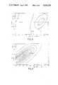
- FIG. 4is an exploded perspective schematic view of the polarizers in a liquid crystal display according to FIG. 1 for a first mode of operation (yellow mode);
- FIG. 5is an exploded perspective schematic view of the polarizers in a liquid crystal display according to FIG. 1 for a second mode of operation (blue mode);
- FIG. 6is a graph illustrating the measured contrast ratio CR as a function of the polarizer orientation in an arrangement according to FIG. 4;
- FIG. 7is a graph illustrating the results corresponding to FIG. 6 for an arrangement according to FIG. 5;
- FIG. 8is a graph illustrating the computed curves of constant contrast ratio as a function of the polarizer orientation and the product ⁇ n ⁇ d for an arrangement with one polarizer and one reflector;
- FIG. 9is a graph illustrating the curves corresponding to FIG. 8 for an arrangement according to FIG. 5;
- FIG. 10is a graph illustrating the curves corresponding to FIG. 8 for an arrangement according to FIG. 4.
- the liquid crystal display shown in FIG. 1consists of two glass support plates 1 and 2 which form a cell with a border 3.
- the border 3as usual, consists of an epoxy cement which contains glass fiber spacers 4. Additional spacers 4 are randomly distributed between the support plates 1 and 2 over the entire viewing area of the display.
- a nematic liquid crystal 5 with positive dielectric anisotropy containing a chiral additiveis filled into the cell.
- the inner surfaces of each support plate 1 and 2have parallel strips of In 2 O 3 electrode layers 6 and 7, whereby the direction of the strips on the one support plate 1 is perpendicular to the direction of the strips on the other support plate 2.
- a dot matrix displayis formed.
- other electrode shapesare also possible, such as, e.g., the known seven-segment arrangement.
- Orientation layers 8 and 9are applied over the electrode layers 6 and 7 and over the the spaces between these electrode layers.
- a linear sheet-type linear polarizer 10is bonded to the outside of the front support plate 1.
- a linear polarizer 11is also bonded to the outside of the rear support plate 2.
- a diffusely scattering, metallic, external reflector 12is placed behind this polarizer 11 (indicated by the dashed line in FIG. 1).
- Such a reflectoris known, e.g. from CH-B-618018.
- the polarizer 11can also be left out. By this means the brightness is improved but the contrast ratio is lowered.
- FIG. 1athe situation is shown when, instead of an external reflector 12, an internal reflector 13 is used, as is known, e.g. from EP-B-060380. As the section shows, this reflector is placed between the electrode layer 7 and the orientation layer 9. Otherwise, except for the polarizer 11, the same elements are present as in FIG. 1.
- FIG. 2represents, for a typical liquid crystal, the theoretical relation between the tilt angle ⁇ of the local optical axis (i.e. the director) of the liquid crystal in the middle of the layer and the applied operating voltage U.
- the angle ⁇was measured in relation to the support plate.
- the tilt angle of the liquid crystal on the support plate in both casesamounts to 28°.
- the parameter ⁇the total twist angle of the liquid crystal within the display cell, runs through the values 210° (curve I), 240° (curve II), 270° (curve III), 300° (curve IV), 330° (curve V) and 360° (curve VI).
- the pitch pis so chosen that the d/p ratio is described by the following formula:
- the values of 210°, 240°, 270°, 300°, 330° and 360°therefore correspond to a d/p ratio of 0.58, 0.67, 0.75, 0.83, 0.91 and 1.0.
- the pitch pis defined in accordance with common usage as the characteristic amount of natural twist produced in the undisturbed nematic liquid crystal by the addition of a chiral additive. The pitch is counted as positive in a system with right-handed twist and negative in a system with left-handed twist.
- the magnitude of the ratio of layer thickness d to pitch p of the liquid crystalbe in the range of 0.50 to 0.95, preferably between 0.65 and 0.85.
- the pitch pis adjusted by adding a specific weight percent of a chiral additive to the nematic liquid crystal. The weight percent depends on the type of liqud crystal and chiral additive and on the layer thickness d.
- the layer thickness dshould be less than 10 ⁇ m and the total twist angle ⁇ within the display cell should be between 180° and 360°, preferably between 240° and 300°.
- the transfer characteristic of the displayi.e. the transmission curve as a function of applied operating voltage
- the range of the bistable behavioris so narrowed that addressing can take place according to the usual multiplexing technique (cf., e.g., IEEE Trans. El. Dev., Vol. ED-21, No. 2, February 1974, pages 146 to 155) with operating voltages outside this range. It was found that within this range the switching times are at least 100 times longer as outside this range.
- the transfer characteristic of the displayhas a similar shape to the curves in FIG. 2, except that the negative slope of the curves (here curves III to VI) should be replaced by a bistable region (hysteresis loop).
- the product of birefringence ⁇ n and layer thickness d of the liquid crystallies within the range 0.6 ⁇ m to 1.4 ⁇ m, preferably between 0.8 ⁇ m and 1.2 ⁇ m.
- the operation of the liquid crystal display of this invention in transmissioncan now be explained as follows: the light linearly polarized by the linear polarizer 10 penetrates the support plate 1 and strikes the liquid crystal aligned on the orientation layer 8 at an angle. Because of the total twist ⁇ and the double refracting properties of the liquid crystal, the originally linearly polarized light is elliptically but variably polarized, depending upon the applied operating voltage.
- the orientation direction of the orientation layer 9 and the direction of vibration of the rear linear polarizer 11also form a certain angle.
- orientation direction used hereis understood to be the projection of the direction of the local optical axis of the liquid crystal immediately adjacent to the orientation layer onto the plane of the orientation layer.
- the direction of vibration of the polarizeris understood to refer to the vibration direction of the electric field vector of the polarized light.
- the elliptically polarized light leaving the liquid crystalis absorbed in the rear polarizer 11, either almost completely or hardly at all, depending upon whether the principal axis of the elliptically polarized light is perpendicular or parallel to the direction of vibration of the polarizer 11.
- An optimum contrastis achieved by suitable choice of the above-mentioned angle between the orientation layers 8 and 9 and of the polarizers 10 and 11. This angle has a magnitude lying between 20° and 70°, preferably between 30° and 60°, with the sense being either clockwise or counter-clockwise.
- the clockwise senseis defined with respect to the incident direction of the light and the angle is taken in reference to the orientation direction of the orientation layer.
- the operating principleis essentially the same as in the transmissive mode.
- the optimum contrast in a system with only one polarizer 10is determined by appropriate choice of the angle between the direction of vibration of the front linear polarizer 10 and the orientation direction of the first orientation layer 8.
- FIGS. 4 and 5show exploded, perspective representations of the arrangement of the polarizers 10 and 11, the orientation layers 8 and 9 as well as the liquid crystal layer 5 located between these layers.
- the total twist ⁇ of the liquid crystal in the layeris made clear by a chain of liquid crystal molecules which are schematically represented by small rectangular platelets. Support plates, border and possible reflectors have been left out for sake of clarity.
- the elements of the cellare arranged along an axis pointing along the propagation direction of the incident light.
- the direction of vibration of the polarizers 10 and 11 as well as the orientation direction of the orientation layers 8 and 9are also indicated by arrows which lie in the corresponding planes perpendicular to the above-mentioned axis of the cell.
- This axis(incident direction of the light) defines a right-handed coordinate system in which angles are counted as positive in the clockwise sense and negative in the counter-clockwise sense.
- the examples of the liquid crystal molecules in the cases of FIGS. 4 and 5therefore form a left-handed screw which has a twist angle ⁇ of -270° in going out from the front orientation layer 8.
- the vibration directions of the polarizers 10 and 11are rotated from the orientation directions of the orientation layers 8 and 9, represented by the dashed lines in the polarizer planes, by the angles ⁇ and ⁇ .
- both angles ⁇ and ⁇are positive.
- only ⁇is positive, whereas ⁇ is negative.
- the angle specificationsalways refer to the rules laid down in FIGS. 4 and 5.
- the inventionhas especially proven to be useful in a reflective display cell with a layer thickness d of 7.6 ⁇ m and a total twist angle ⁇ of the liquid crystal of -270°.
- the d/p ratio in this caseis -0.75.
- the first orientation layer 8is produced by oblique vacuum deposition of SiO at an angle of 5° to the plate plane and aligns the adjoining liquid crystal molecules in such a way that the tilt angle between the local optical axis of the liquid crystal at the orientation layer and the projection of this optical axis on the plane plate, i.e. the orientation direction, amounts to 28°.
- the direction of vibration of the front polarizer 10 and the orientation direction of the orientation layer 8form an angle of about 30°.
- the second orientation layer 9is a rubbed polymer layer which gives a tilt angle of 1°.
- the liquid crystal 5consists of the nematic mixture ZLI-1840 from the firm of Merck, FRG, with 2.05 percent by weight of the chiral additive cholesteryl nonanoate. This liquid crystal has a positive dielectric anisotropy of +12.2 and a birefringence of 0.15.
- the temperature rangeextends from 258 K to 363 K, and the viscosity is 1.18 ⁇ 10 -4 m 2 /s at 273 K and 3.1 ⁇ 10 -3 m 2 /s at 293 K.
- the operating voltagesare 1.90 V for the non-selected state (dark) and 2.10 V for the selected state (bright).
- the displayIn the bright state, the display is completely achromatic, in the dark condition it is deep blue.
- an optical retardation platesuch as, e.g., a ⁇ /4 plate, is used between the front linear polarizer 10 and the front support plate 1, the color of the display can be correspondingly changed. It has an excellent range of viewing angles independent of the direction of the illumination.
- the on and off switching times of the displayare 0.4 s at 296 K.
- Another especially preferred embodiment of the inventionconsists of a reflective display cell with a 0.7 mm thick support plate 1 and a 0.5 mm thick support plate 2.
- the layer thicknessis 6.5 ⁇ m.
- This display cellis provided with a front polarizer 10, a rear polarizer 11 and an external reflector 12.
- Both orientation layers 8 and 9are prepared by oblique vacuum deposition of SiO at an angle of 5° to the plate plane. These layers orient the neighboring liquid crystal molecules in such a way that the optical axis of the liquid crystal forms a tilt angle of 28° with respect to the plate plane.
- the orientation layer 8 and 9are arranged so that the total twist ⁇ makes a left-handed spiral of -250°.
- the nematic mixture ZLI-1840 with a chiral additive of 2.56 weight percent of cholesteryl nonanoateis filled into the cell.
- the angle ⁇ between the vibration direction of the front linear polarizer 10 and the orientation direction of its associated orientation layer 8 and the angle ⁇ between the vibration direction of the rear linear polarizer 11 and the orientation direction of its associated orientation layer 9are ⁇ 45°. Contrast curves are given in FIG.
- V s and V nsare the usual select and non-select addressing voltages as given in the article appearing in IEEE Trans. El. Dev. that was already mentioned.
- the ratio V s /V nsis then 1.106 for a multiplex rate of 100:1.
- a liquid crystal mixtureconsisting of 95.6 wt. % ZLI-2392 (Merck), 2.5 wt. % S 811 (Merck) and 1.9 wt. % CB 15 (BDH) was used for these measurements.
- the total layer twist anglewas -270°, the surface tilt angle 24°, the layer thickness 6.3 ⁇ m and the birefringence 0.15.
- FIG. 8makes it clear that in the case of a cell operating in the reflective mode with one polarizer a maximal contrast ratio CR of about 3.6:1 is only then achieved if the angle ⁇ is about 20° and ⁇ n ⁇ d is approximately 1.13 ⁇ m. For this case a surface tilt angle of 28° was assumed.
- this inventionmakes possible a highly multiplexable, high contrast and fast liquid crystal display having a wide range of viewing angles, which in addition can be manufactured using the proven technology of the conventional TN (Twisted Nematic) display cells.
Landscapes
- Physics & Mathematics (AREA)
- Nonlinear Science (AREA)
- General Physics & Mathematics (AREA)
- Optics & Photonics (AREA)
- Chemical & Material Sciences (AREA)
- Crystallography & Structural Chemistry (AREA)
- Liquid Crystal (AREA)
- Liquid Crystal Substances (AREA)
Abstract
Description
d/p=φ/360° (1)
______________________________________ curve A V.sub.s = 1.580 V contrast ratio = 19.8 V.sub.ns = 1.429 V curve B V.sub.s = 1.609 V contrast ratio = 11.8 V.sub.ns = 1.456 V ______________________________________
______________________________________ (2) β + γ ≅ ± 90° (FIG. 4) or (3) β + γ ≅ 0° (FIG. 5) ______________________________________
______________________________________ Designation List ______________________________________ 1, 2support plates 3 border 4spacers 5 nematic6, 7 liquid crystal 8, 9 orientation layers 10 front electrode layers linear polarizer 11 rearlinear polarizer 12 external reflector 13 internal reflector φ total twist angle of the liquid crystal within the display cell θ tilt angle of the liquid crystal in the middle of the layer U applied operating voltage d thickness of the liquid crystal layer p pitch of the liquid crystal layer β, γ angle ______________________________________ FIG. 3: Helligkeit = brightness
Claims (16)
Applications Claiming Priority (4)
| Application Number | Priority Date | Filing Date | Title |
|---|---|---|---|
| CH381983ACH664027A5 (en) | 1983-07-12 | 1983-07-12 | LCD with twisted nematic crystal between support plates |
| CH3819/83 | 1983-07-12 | ||
| CH583583ACH665491A5 (en) | 1983-10-28 | 1983-10-28 | LCD with twisted nematic crystal between support plates |
| CH5835/83 | 1983-10-28 |
Related Child Applications (1)
| Application Number | Title | Priority Date | Filing Date |
|---|---|---|---|
| US06/908,667ContinuationUS4697884A (en) | 1983-07-12 | 1986-09-17 | Liquid crystal display having degree of twist and thickness for improved multiplexing |
Publications (1)
| Publication Number | Publication Date |
|---|---|
| US4634229Atrue US4634229A (en) | 1987-01-06 |
Family
ID=25693920
Family Applications (2)
| Application Number | Title | Priority Date | Filing Date |
|---|---|---|---|
| US06/626,380Expired - LifetimeUS4634229A (en) | 1983-07-12 | 1984-06-29 | Liquid crystal display |
| US06/908,667Expired - LifetimeUS4697884A (en) | 1983-07-12 | 1986-09-17 | Liquid crystal display having degree of twist and thickness for improved multiplexing |
Family Applications After (1)
| Application Number | Title | Priority Date | Filing Date |
|---|---|---|---|
| US06/908,667Expired - LifetimeUS4697884A (en) | 1983-07-12 | 1986-09-17 | Liquid crystal display having degree of twist and thickness for improved multiplexing |
Country Status (14)
| Country | Link |
|---|---|
| US (2) | US4634229A (en) |
| EP (1) | EP0131216B1 (en) |
| KR (1) | KR900008064B1 (en) |
| CA (1) | CA1242784A (en) |
| DD (1) | DD222433A5 (en) |
| DE (2) | DE3467044D1 (en) |
| FR (1) | FR2549268B1 (en) |
| GB (1) | GB2143336B (en) |
| HK (1) | HK54890A (en) |
| IN (1) | IN161652B (en) |
| NL (1) | NL8402189A (en) |
| NO (1) | NO167241C (en) |
| PH (1) | PH24617A (en) |
| SG (1) | SG20690G (en) |
Cited By (37)
| Publication number | Priority date | Publication date | Assignee | Title |
|---|---|---|---|---|
| US4596446A (en)* | 1982-06-29 | 1986-06-24 | The Secretary Of State For Defence In Her Britannic Majesty's Government Of The United Kingdom Of Great Britain And Northern Ireland | Liquid crystal devices with particular cholesteric pitch-cell thickness ratio |
| EP0251665A1 (en)* | 1986-06-28 | 1988-01-07 | Kabushiki Kaisha Toshiba | Liquid crystal device |
| US4776674A (en)* | 1986-06-25 | 1988-10-11 | American Telephone And Telegraph Company, At&T Bell Laboratories | Liquid crystal device with chemically-induced high-tilt alignment coating |
| FR2614437A1 (en)* | 1987-04-23 | 1988-10-28 | Seiko Instr Inc | ELECTRO-OPTICAL MODULATOR |
| DE3822604A1 (en)* | 1987-07-17 | 1989-01-26 | Hitachi Ltd | Liquid-crystal display element |
| US4856875A (en)* | 1986-12-29 | 1989-08-15 | Sharp Kabushiki Kaisha | Liquid-crystal display devices of twisted nematic type |
| US4904060A (en)* | 1987-11-23 | 1990-02-27 | Asulab, S.A. | Liquid crystal display cell having a diffusely-reflective counter electrode |
| US4909606A (en)* | 1986-04-22 | 1990-03-20 | Seiko Epson Corporation | Liquid crystal display device |
| US4909605A (en)* | 1986-09-12 | 1990-03-20 | Konishiroku Photo Industry Co., Ltd. | Liquid crystal display device |
| US4917465A (en)* | 1989-03-28 | 1990-04-17 | In Focus Systems, Inc. | Color display system |
| US4923286A (en)* | 1986-02-27 | 1990-05-08 | Asulab S.A. | Display cell |
| US4941737A (en)* | 1987-10-07 | 1990-07-17 | Sharp Kabushiki Kaisha | Liquid-crystal display device using twisted nematic liquid crystal molecules |
| US4944578A (en)* | 1988-07-21 | 1990-07-31 | Telex Communications | Color graphic imager utilizing a liquid crystal display |
| US4952029A (en)* | 1987-12-03 | 1990-08-28 | Sharp Kabushiki Kaisha | Two celled liquid crystal display device with dependency of birefringence on wavelength larger in first cell |
| US5044735A (en)* | 1985-11-29 | 1991-09-03 | Konishiroku Photo Industry Co., Ltd. | Liquid crystal display device for providing sufficiently high contrast ratio and excellent response time |
| US5048933A (en)* | 1989-04-14 | 1991-09-17 | Konica Corporation | Transmission type liquid crystal display device |
| US5050965A (en)* | 1989-09-01 | 1991-09-24 | In Focus Systems, Inc. | Color display using supertwisted nematic liquid crystal material |
| US5058998A (en)* | 1988-09-16 | 1991-10-22 | Casio Computer Co., Ltd. | Liquid crystal display devide with a twisted alignment state |
| US5089810A (en)* | 1990-04-09 | 1992-02-18 | Computer Accessories Corporation | Stacked display panel construction and method of making same |
| US5119220A (en)* | 1988-01-28 | 1992-06-02 | Sanyo Electric Co., Ltd. | Liquid crystal display device with a phase plate for shadow compensation |
| US5153568A (en)* | 1988-07-21 | 1992-10-06 | Proxima Corporation | Liquid crystal display panel system and method of using same |
| US5188758A (en)* | 1986-03-19 | 1993-02-23 | Merck Patent Gesellschaft Mit Beschraenkter Haftung | Electrooptical display element using a supertwist liquid crystal having specified elastic constants |
| US5215677A (en)* | 1985-09-27 | 1993-06-01 | Sanyo Electric Co., Ltd. | Liquid crystal display device |
| US5229031A (en)* | 1989-05-17 | 1993-07-20 | Seiko Epson Corporation | Liquid crystal display device |
| US5302946A (en)* | 1988-07-21 | 1994-04-12 | Leonid Shapiro | Stacked display panel construction and method of making same |
| US5488499A (en)* | 1992-07-16 | 1996-01-30 | Seiko Epson Corporation | Liquid crystal display device utilizing a chiral nematic liquid crystal medium operative relative to two metastable states |
| US5876626A (en)* | 1988-10-20 | 1999-03-02 | Merck Patent Gesellschaft Mit Beschrankter Haftung | Supertwist liquid crystal display |
| EP0802684A3 (en)* | 1996-04-19 | 1999-04-14 | Ncr International Inc. | Method of controlling viewability of a display screen and a device therefor |
| USRE36654E (en)* | 1989-03-28 | 2000-04-11 | In Focus Systems, Inc. | Stacked LCD color display |
| US6151088A (en)* | 1996-08-27 | 2000-11-21 | Ricoh Co., Ltd. | Liquid crystal display apparatus |
| US6252571B1 (en) | 1995-05-17 | 2001-06-26 | Seiko Epson Corporation | Liquid crystal display device and its drive method and the drive circuit and power supply circuit device used therein |
| US6833887B1 (en)* | 1996-05-10 | 2004-12-21 | Citizen Watch Co., Ltd. | Liquid crystal shutter and method of driving the same |
| US20070273811A1 (en)* | 2003-05-16 | 2007-11-29 | Janez Pirs | High Contrast Viewing Angle Lcd Light-Switching Element |
| WO2013140083A1 (en) | 2012-03-19 | 2013-09-26 | Solarwell | Light-emitting device containing flattened anisotropic colloidal semiconductor nanocrystals and processes for manufacturing such devices |
| US9958137B2 (en) | 2012-03-19 | 2018-05-01 | Nexdot | Light-emitting device containing anisotropic flat colloidal semiconductor nanocrystals and methods of manufacture thereof |
| US11086162B1 (en)* | 2020-04-26 | 2021-08-10 | Tcl China Star Optoelectronics Technology Co., Ltd. | Display panel and display device |
| EP3146251B2 (en)† | 2014-05-20 | 2022-03-02 | Paolo De Nora | Extensible hose and hose assembly |
Families Citing this family (59)
| Publication number | Priority date | Publication date | Assignee | Title |
|---|---|---|---|---|
| JPS6050511A (en)* | 1983-08-31 | 1985-03-20 | Hitachi Ltd | Liquid crystal display element |
| JPS61193125A (en)* | 1985-02-22 | 1986-08-27 | Hitachi Ltd | Liquid crystal display element |
| JPS61210324A (en)* | 1985-03-15 | 1986-09-18 | Hitachi Ltd | Liquid crystal display element |
| JPH0656459B2 (en)* | 1985-04-05 | 1994-07-27 | 株式会社日立製作所 | Liquid crystal display element |
| CA1281114C (en)* | 1985-09-25 | 1991-03-05 | Kokichi Ito | Liquid crystal electro-optical element with adhesive particles |
| DE3684977D1 (en)* | 1985-09-27 | 1992-05-27 | Sanyo Electric Co | LIQUID CRYSTAL DISPLAY DEVICE. |
| JPS62194224A (en)* | 1986-02-20 | 1987-08-26 | Sharp Corp | Twisted nematic type liquid crystal display element |
| US4726659A (en)* | 1986-02-24 | 1988-02-23 | Rca Corporation | Display device having different alignment layers |
| DE3609141A1 (en)* | 1986-03-19 | 1987-09-24 | Merck Patent Gmbh | ELECTROOPTICAL DISPLAY ELEMENT |
| US4818074A (en)* | 1986-09-03 | 1989-04-04 | Ricoh Company, Ltd. | Projection device for irradiating a light to a display device and optically magnifying and projecting a reflection light therefrom |
| DE3774977D1 (en)* | 1986-09-12 | 1992-01-16 | Hoffmann La Roche | LIQUID CRYSTAL DISPLAY. |
| JPS63220221A (en)* | 1987-03-10 | 1988-09-13 | Sharp Corp | Color liquid crystal display element |
| JPS63234225A (en)* | 1987-03-23 | 1988-09-29 | Sharp Corp | liquid crystal display device |
| FR2613566B1 (en)* | 1987-04-06 | 1989-06-09 | Commissariat Energie Atomique | ACTIVE MATRIX SCREEN FOR COLOR DISPLAY OF TELEVISION IMAGES, CONTROL SYSTEM AND METHOD FOR MANUFACTURING SAID SCREEN |
| NL8801164A (en)* | 1987-06-10 | 1989-01-02 | Philips Nv | DISPLAY FOR USE IN REFLECTION. |
| KR0134974B1 (en)* | 1987-07-29 | 1998-04-22 | 미다 가쓰시게 | Nematic liquid crystal display with twisted spiral structure |
| US5044733A (en)* | 1987-08-19 | 1991-09-03 | Ricoh Company, Ltd. | Super twisted nematic liquid crystal display device having the standard deviation of the spherical grains being not more than 3% and the dispersion quantity of the spherical grains being 100-200 grains/mm2 |
| DE3887436T2 (en)* | 1987-10-13 | 1994-05-11 | Fujitsu Ltd | Liquid crystal display panel. |
| JPH01120527A (en)* | 1987-11-04 | 1989-05-12 | Sharp Corp | liquid crystal display device |
| DE3741997C2 (en)* | 1987-12-11 | 1997-07-17 | Vdo Schindling | Method for driving an STN liquid crystal cell |
| US4936654A (en)* | 1988-01-28 | 1990-06-26 | Sanyo Electric Co., Ltd. | Liquid crystal display device |
| DE3807958B4 (en)* | 1988-03-10 | 2004-03-18 | Merck Patent Gmbh | Super twisted liquid crystal display element |
| DE3835803A1 (en)* | 1988-03-10 | 1990-04-26 | Merck Patent Gmbh | SUPERTWIST-LIQUID CRYSTAL DISPLAY ELEMENT AND LIQUID MIXTURE |
| US5082353A (en)* | 1988-05-11 | 1992-01-21 | Kabushiki Kaisha Toshiba | Liquid-crystal display apparatus |
| JP2621385B2 (en)* | 1988-07-06 | 1997-06-18 | セイコーエプソン株式会社 | Electro-optical device |
| WO1990000756A1 (en)* | 1988-07-14 | 1990-01-25 | Seiko Epson Corporation | Reflection-type liquid crystal electro-optical device and projection-type display device using the same |
| EP0352101B1 (en)* | 1988-07-19 | 1994-09-14 | Sharp Kabushiki Kaisha | A double-layered type liquid-crystal display device |
| JPH0642125B2 (en)* | 1988-10-04 | 1994-06-01 | シャープ株式会社 | Projection equipment |
| DE3835804B4 (en)* | 1988-10-20 | 2006-12-28 | Merck Patent Gmbh | Nematic liquid-crystal mixture |
| DE3843767A1 (en)* | 1988-12-24 | 1990-07-05 | Nokia Unterhaltungselektronik | LIQUID CRYSTAL DISPLAY FOR BLACK / WHITE DISPLAY |
| US4991924A (en)* | 1989-05-19 | 1991-02-12 | Cornell Research Foundation, Inc. | Optical switches using cholesteric or chiral nematic liquid crystals and method of using same |
| DE3923064B4 (en)* | 1989-07-13 | 2004-08-05 | Merck Patent Gmbh | Liquid crystal mixture and Supertwist liquid crystal display containing it |
| JPH03122615A (en)* | 1989-10-06 | 1991-05-24 | Toshiba Corp | Liquid crystal display device |
| JP2924055B2 (en)* | 1989-12-08 | 1999-07-26 | セイコーエプソン株式会社 | Reflective liquid crystal display |
| JP2717731B2 (en)* | 1991-02-08 | 1998-02-25 | 株式会社日立製作所 | Liquid crystal display device |
| JPH03248121A (en)* | 1991-02-08 | 1991-11-06 | Hitachi Ltd | liquid crystal display element |
| US6392689B1 (en)* | 1991-02-21 | 2002-05-21 | Eugene Dolgoff | System for displaying moving images pseudostereoscopically |
| US5184156A (en)* | 1991-11-12 | 1993-02-02 | Reliant Laser Corporation | Glasses with color-switchable, multi-layered lenses |
| EP0559137B1 (en)* | 1992-03-03 | 1998-06-03 | Matsushita Electric Industrial Co., Ltd. | Active matrix type twisted nematic liquid crystal display |
| US5696570A (en)* | 1992-04-16 | 1997-12-09 | Merck Patent Gesellschaft Mit Beschrankter Haftung | TN cell having improved display of grey shades |
| US5327269A (en)* | 1992-05-13 | 1994-07-05 | Standish Industries, Inc. | Fast switching 270° twisted nematic liquid crystal device and eyewear incorporating the device |
| US6693696B1 (en)* | 1992-06-30 | 2004-02-17 | Semiconductor Energy Laboratory Co., Ltd. | Electro-optical device |
| JPH0784252A (en)* | 1993-09-16 | 1995-03-31 | Sharp Corp | Liquid crystal display |
| US5432624A (en)* | 1993-12-03 | 1995-07-11 | Reliant Technologies, Inc. | Optical display unit in which light passes a first cell, reflects, then passes a second cell |
| JP2927662B2 (en)* | 1993-12-24 | 1999-07-28 | シャープ株式会社 | Liquid crystal display |
| US5574583A (en)* | 1994-08-02 | 1996-11-12 | Hyundai Electronics Industries Co. Ltd. | Liquid crystal display device having a compensation layer and method for fabricating the same |
| US6258443B1 (en) | 1994-09-28 | 2001-07-10 | Reflexite Corporation | Textured retroreflective prism structures and molds for forming same |
| JPH08166605A (en)* | 1994-10-14 | 1996-06-25 | Sharp Corp | Liquid crystal display |
| DE69622942T2 (en)* | 1995-01-23 | 2003-05-28 | Asahi Glass Co., Ltd. | Liquid-crystal ANZEIGVORRICHTUNG |
| JPH0850271A (en)* | 1995-07-10 | 1996-02-20 | Hitachi Ltd | Liquid crystal display element |
| US6094252A (en)* | 1995-09-05 | 2000-07-25 | Sharp Kabushiki Kaisha | GH LCD having particular parameters and characteristics |
| KR100405893B1 (en)* | 1995-10-23 | 2004-10-06 | 가부시끼가이샤 히다치 세이사꾸쇼 | Liquid crystal display |
| US5731404A (en) | 1995-11-01 | 1998-03-24 | E. I. Du Pont De Nemours And Company | Polyimide film from pyromellitic dianhydride and a bis(4-aminophenoxy) aromatic compound as an alignment layer for liquid crystal displays |
| DE69823875T2 (en)* | 1997-10-08 | 2005-04-21 | Hewlett Packard Co | ORIENTATION METHOD FOR LIQUID CRYSTAL DEVICE AND METHOD FOR MANUFACTURING THIS DEVICE |
| US6714276B2 (en)* | 2000-02-08 | 2004-03-30 | Sharp Kabushiki Kaisha | Liquid crystal display device |
| DE10047091A1 (en)* | 2000-09-21 | 2002-04-11 | Merck Patent Gmbh | Liquid crystalline mixtures |
| DE10253874A1 (en)* | 2002-11-12 | 2004-05-27 | Carl Zeiss Smt Ag | Method for forming optical functional component for adjusting micro lithographic projection illumination installations, using charge coupled device (CCD) camera |
| CN101441365B (en)* | 2005-04-18 | 2010-11-03 | 胜华科技股份有限公司 | Bistable liquid crystal display device |
| DE102009017301A1 (en) | 2009-02-21 | 2010-08-26 | Robert Bosch Gmbh | Gear transmission with a arranged on a hollow shaft gear |
Citations (10)
| Publication number | Priority date | Publication date | Assignee | Title |
|---|---|---|---|---|
| FR2416519A1 (en)* | 1978-02-06 | 1979-08-31 | Ebauches Sa | PASSIVE ELECTRO-OPTICAL DISPLAY CELL |
| GB2076554A (en)* | 1980-05-09 | 1981-12-02 | Hitachi Ltd | Liquid crystal display device |
| GB2087583A (en)* | 1980-10-20 | 1982-05-26 | Western Electric Co | Bistable liquid crystal twist cell |
| JPS57133438A (en)* | 1981-02-13 | 1982-08-18 | Hitachi Ltd | Liquid crystal display device |
| US4362771A (en)* | 1980-10-20 | 1982-12-07 | Hitachi, Ltd. | Liquid crystal display element with gap controlling material and process for production thereof |
| US4496220A (en)* | 1977-03-21 | 1985-01-29 | U.S. Philips Corporation | Information display device comprising a liquid crystal cell |
| US4505548A (en)* | 1980-10-20 | 1985-03-19 | At&T Bell Laboratories | Bistable liquid crystal twist cell |
| US4521080A (en)* | 1974-07-01 | 1985-06-04 | Sharp Kabushiki Kaisha | Field effect mode liquid crystal display |
| US4564266A (en)* | 1982-04-28 | 1986-01-14 | Centre National De La Recherche Scientifique (Cnrs) | Electro-optical devices using liquid crystals having a twist in a plane perpendicular to substrates |
| US4579425A (en)* | 1982-07-29 | 1986-04-01 | Sharp Kabushiki Kaisha | Multiplexable liquid crystal display with reduced hysteresis |
Family Cites Families (4)
| Publication number | Priority date | Publication date | Assignee | Title |
|---|---|---|---|---|
| US3656834A (en)* | 1970-12-09 | 1972-04-18 | Ibm | Additive for liquid crystal material |
| FR2356173A1 (en)* | 1976-06-21 | 1978-01-20 | Gen Electric | PROCESS FOR IMPROVING THE DESCENT TIME OF A DISPLAY DEVICE COMPOSED OF NEMATIC PROPELLERED LIQUID CRYSTALS |
| JPS5352140A (en)* | 1976-10-22 | 1978-05-12 | Hitachi Ltd | Liquid crystal display device |
| ATE34468T1 (en)* | 1982-06-29 | 1988-06-15 | Secr Defence Brit | LIQUID CRYSTAL DEVICES. |
- 1984
- 1984-06-19ININ448/MAS/84Apatent/IN161652B/enunknown
- 1984-06-28EPEP84107507Apatent/EP0131216B1/ennot_activeExpired
- 1984-06-28DEDE8484107507Tpatent/DE3467044D1/ennot_activeExpired
- 1984-06-29DEDE19843423993patent/DE3423993A1/enactiveGranted
- 1984-06-29USUS06/626,380patent/US4634229A/ennot_activeExpired - Lifetime
- 1984-07-09NONO842799Apatent/NO167241C/ennot_activeIP Right Cessation
- 1984-07-09KRKR1019840003975Apatent/KR900008064B1/ennot_activeExpired
- 1984-07-10FRFR8410952Apatent/FR2549268B1/ennot_activeExpired
- 1984-07-10PHPH30959Apatent/PH24617A/enunknown
- 1984-07-10DDDD84265107Apatent/DD222433A5/enunknown
- 1984-07-10NLNL8402189Apatent/NL8402189A/ennot_activeApplication Discontinuation
- 1984-07-12GBGB08417776Apatent/GB2143336B/ennot_activeExpired
- 1984-07-12CACA000458749Apatent/CA1242784A/ennot_activeExpired
- 1986
- 1986-09-17USUS06/908,667patent/US4697884A/ennot_activeExpired - Lifetime
- 1990
- 1990-03-14SGSG206/90Apatent/SG20690G/enunknown
- 1990-07-19HKHK548/90Apatent/HK54890A/ennot_activeIP Right Cessation
Patent Citations (11)
| Publication number | Priority date | Publication date | Assignee | Title |
|---|---|---|---|---|
| US4521080A (en)* | 1974-07-01 | 1985-06-04 | Sharp Kabushiki Kaisha | Field effect mode liquid crystal display |
| US4496220A (en)* | 1977-03-21 | 1985-01-29 | U.S. Philips Corporation | Information display device comprising a liquid crystal cell |
| FR2416519A1 (en)* | 1978-02-06 | 1979-08-31 | Ebauches Sa | PASSIVE ELECTRO-OPTICAL DISPLAY CELL |
| GB2017327A (en)* | 1978-02-06 | 1979-10-03 | Ebauches Sa | Electro-optic passive display cell |
| GB2076554A (en)* | 1980-05-09 | 1981-12-02 | Hitachi Ltd | Liquid crystal display device |
| GB2087583A (en)* | 1980-10-20 | 1982-05-26 | Western Electric Co | Bistable liquid crystal twist cell |
| US4362771A (en)* | 1980-10-20 | 1982-12-07 | Hitachi, Ltd. | Liquid crystal display element with gap controlling material and process for production thereof |
| US4505548A (en)* | 1980-10-20 | 1985-03-19 | At&T Bell Laboratories | Bistable liquid crystal twist cell |
| JPS57133438A (en)* | 1981-02-13 | 1982-08-18 | Hitachi Ltd | Liquid crystal display device |
| US4564266A (en)* | 1982-04-28 | 1986-01-14 | Centre National De La Recherche Scientifique (Cnrs) | Electro-optical devices using liquid crystals having a twist in a plane perpendicular to substrates |
| US4579425A (en)* | 1982-07-29 | 1986-04-01 | Sharp Kabushiki Kaisha | Multiplexable liquid crystal display with reduced hysteresis |
Non-Patent Citations (8)
| Title |
|---|
| B. P. Application 82 18821 filed Jun. 29, 1982, published Jan. 25, 1984, Raynes.* |
| JP Publ. 57 133438 publ. Aug. 18, 1982, (Hitachi 1).* |
| JP Publ. 57-133438 publ. Aug. 18, 1982, (Hitachi 1). |
| JP Publ. 60 162225 and 60 162226 publ. Aug. 24, 1985, (Hitachi 4).* |
| JP Publ. 60 5011 publ. Mar. 20, 1985, (Hitachi 2).* |
| JP Publ. 60-162225 and 60-162226 publ. Aug. 24, 1985, (Hitachi 4). |
| JP Publ. 60-5011 publ. Mar. 20, 1985, (Hitachi 2). |
| JP Publ. 6a73525 publ. Apr. 25, 1985, (Hitachi 3).* |
Cited By (44)
| Publication number | Priority date | Publication date | Assignee | Title |
|---|---|---|---|---|
| US4596446A (en)* | 1982-06-29 | 1986-06-24 | The Secretary Of State For Defence In Her Britannic Majesty's Government Of The United Kingdom Of Great Britain And Northern Ireland | Liquid crystal devices with particular cholesteric pitch-cell thickness ratio |
| US5215677A (en)* | 1985-09-27 | 1993-06-01 | Sanyo Electric Co., Ltd. | Liquid crystal display device |
| US5044735A (en)* | 1985-11-29 | 1991-09-03 | Konishiroku Photo Industry Co., Ltd. | Liquid crystal display device for providing sufficiently high contrast ratio and excellent response time |
| US4923286A (en)* | 1986-02-27 | 1990-05-08 | Asulab S.A. | Display cell |
| US5188758A (en)* | 1986-03-19 | 1993-02-23 | Merck Patent Gesellschaft Mit Beschraenkter Haftung | Electrooptical display element using a supertwist liquid crystal having specified elastic constants |
| US4909606A (en)* | 1986-04-22 | 1990-03-20 | Seiko Epson Corporation | Liquid crystal display device |
| US4776674A (en)* | 1986-06-25 | 1988-10-11 | American Telephone And Telegraph Company, At&T Bell Laboratories | Liquid crystal device with chemically-induced high-tilt alignment coating |
| US4779958A (en)* | 1986-06-28 | 1988-10-25 | Kabushiki Kaisha Toshiba | Liquid crystal device having different natural and induced twists |
| EP0251665A1 (en)* | 1986-06-28 | 1988-01-07 | Kabushiki Kaisha Toshiba | Liquid crystal device |
| US4909605A (en)* | 1986-09-12 | 1990-03-20 | Konishiroku Photo Industry Co., Ltd. | Liquid crystal display device |
| US4856875A (en)* | 1986-12-29 | 1989-08-15 | Sharp Kabushiki Kaisha | Liquid-crystal display devices of twisted nematic type |
| GB2204174A (en)* | 1987-04-23 | 1988-11-02 | Seiko Instr Inc | Electro-optical modulator |
| FR2614437A1 (en)* | 1987-04-23 | 1988-10-28 | Seiko Instr Inc | ELECTRO-OPTICAL MODULATOR |
| GB2204174B (en)* | 1987-04-23 | 1991-03-13 | Seiko Instr Inc | Electro-optical modulator |
| DE3822604A1 (en)* | 1987-07-17 | 1989-01-26 | Hitachi Ltd | Liquid-crystal display element |
| US4941737A (en)* | 1987-10-07 | 1990-07-17 | Sharp Kabushiki Kaisha | Liquid-crystal display device using twisted nematic liquid crystal molecules |
| US4904060A (en)* | 1987-11-23 | 1990-02-27 | Asulab, S.A. | Liquid crystal display cell having a diffusely-reflective counter electrode |
| US4952029A (en)* | 1987-12-03 | 1990-08-28 | Sharp Kabushiki Kaisha | Two celled liquid crystal display device with dependency of birefringence on wavelength larger in first cell |
| US5119220A (en)* | 1988-01-28 | 1992-06-02 | Sanyo Electric Co., Ltd. | Liquid crystal display device with a phase plate for shadow compensation |
| US4944578A (en)* | 1988-07-21 | 1990-07-31 | Telex Communications | Color graphic imager utilizing a liquid crystal display |
| US5302946A (en)* | 1988-07-21 | 1994-04-12 | Leonid Shapiro | Stacked display panel construction and method of making same |
| US5153568A (en)* | 1988-07-21 | 1992-10-06 | Proxima Corporation | Liquid crystal display panel system and method of using same |
| US5058998A (en)* | 1988-09-16 | 1991-10-22 | Casio Computer Co., Ltd. | Liquid crystal display devide with a twisted alignment state |
| US5876626A (en)* | 1988-10-20 | 1999-03-02 | Merck Patent Gesellschaft Mit Beschrankter Haftung | Supertwist liquid crystal display |
| US4917465A (en)* | 1989-03-28 | 1990-04-17 | In Focus Systems, Inc. | Color display system |
| USRE36654E (en)* | 1989-03-28 | 2000-04-11 | In Focus Systems, Inc. | Stacked LCD color display |
| US5048933A (en)* | 1989-04-14 | 1991-09-17 | Konica Corporation | Transmission type liquid crystal display device |
| US5229031A (en)* | 1989-05-17 | 1993-07-20 | Seiko Epson Corporation | Liquid crystal display device |
| US5050965A (en)* | 1989-09-01 | 1991-09-24 | In Focus Systems, Inc. | Color display using supertwisted nematic liquid crystal material |
| US5089810A (en)* | 1990-04-09 | 1992-02-18 | Computer Accessories Corporation | Stacked display panel construction and method of making same |
| US5488499A (en)* | 1992-07-16 | 1996-01-30 | Seiko Epson Corporation | Liquid crystal display device utilizing a chiral nematic liquid crystal medium operative relative to two metastable states |
| US6072558A (en)* | 1992-07-16 | 2000-06-06 | Seiko Epson Corporation | Electrooptical element switchable between a plurality of metabstable states |
| US6252571B1 (en) | 1995-05-17 | 2001-06-26 | Seiko Epson Corporation | Liquid crystal display device and its drive method and the drive circuit and power supply circuit device used therein |
| EP0802684A3 (en)* | 1996-04-19 | 1999-04-14 | Ncr International Inc. | Method of controlling viewability of a display screen and a device therefor |
| US7002643B2 (en) | 1996-05-10 | 2006-02-21 | Citizen Watch Co., Ltd. | Liquid crystal shutter |
| US6833887B1 (en)* | 1996-05-10 | 2004-12-21 | Citizen Watch Co., Ltd. | Liquid crystal shutter and method of driving the same |
| US6151088A (en)* | 1996-08-27 | 2000-11-21 | Ricoh Co., Ltd. | Liquid crystal display apparatus |
| US20070273811A1 (en)* | 2003-05-16 | 2007-11-29 | Janez Pirs | High Contrast Viewing Angle Lcd Light-Switching Element |
| US7420631B2 (en)* | 2003-05-16 | 2008-09-02 | Institut Jozef Stefan | High contrast, wide viewing angle LCD light-switching element |
| WO2013140083A1 (en) | 2012-03-19 | 2013-09-26 | Solarwell | Light-emitting device containing flattened anisotropic colloidal semiconductor nanocrystals and processes for manufacturing such devices |
| US9447927B2 (en) | 2012-03-19 | 2016-09-20 | Nexdot | Light-emitting device containing flattened anisotropic colloidal semiconductor nanocrystals and processes for manufacturing such devices |
| US9958137B2 (en) | 2012-03-19 | 2018-05-01 | Nexdot | Light-emitting device containing anisotropic flat colloidal semiconductor nanocrystals and methods of manufacture thereof |
| EP3146251B2 (en)† | 2014-05-20 | 2022-03-02 | Paolo De Nora | Extensible hose and hose assembly |
| US11086162B1 (en)* | 2020-04-26 | 2021-08-10 | Tcl China Star Optoelectronics Technology Co., Ltd. | Display panel and display device |
Also Published As
| Publication number | Publication date |
|---|---|
| SG20690G (en) | 1990-07-06 |
| FR2549268A1 (en) | 1985-01-18 |
| KR900008064B1 (en) | 1990-10-31 |
| IN161652B (en) | 1988-01-09 |
| DE3467044D1 (en) | 1987-12-03 |
| CA1242784A (en) | 1988-10-04 |
| GB2143336B (en) | 1987-04-01 |
| EP0131216A2 (en) | 1985-01-16 |
| EP0131216A3 (en) | 1985-03-13 |
| US4697884A (en) | 1987-10-06 |
| DE3423993C2 (en) | 1988-06-23 |
| NO167241C (en) | 1991-10-16 |
| GB2143336A (en) | 1985-02-06 |
| FR2549268B1 (en) | 1985-12-13 |
| NL8402189A (en) | 1985-02-01 |
| KR850001438A (en) | 1985-03-18 |
| US4697884B1 (en) | 1990-08-28 |
| GB8417776D0 (en) | 1984-08-15 |
| EP0131216B1 (en) | 1987-10-28 |
| NO167241B (en) | 1991-07-08 |
| PH24617A (en) | 1990-08-17 |
| HK54890A (en) | 1990-07-27 |
| NO842799L (en) | 1985-01-14 |
| DD222433A5 (en) | 1985-05-15 |
| DE3423993A1 (en) | 1985-01-24 |
Similar Documents
| Publication | Publication Date | Title |
|---|---|---|
| US4634229A (en) | Liquid crystal display | |
| US5576867A (en) | Liquid crystal switching elements having a parallel electric field and βo which is not 0° or 90° | |
| US5018839A (en) | Liquid crystal display device | |
| US4653865A (en) | Liquid crystal display device | |
| US4664482A (en) | Liquid crystal display device having a chiral additive and angularly displaced polarizers | |
| US6278505B1 (en) | Liquid crystal reflective display | |
| KR100254041B1 (en) | Liquid crystal display device that compensates for residual phase difference of liquid crystal layer | |
| JPH041330B2 (en) | ||
| US5119216A (en) | Electro-optical device | |
| KR920004895B1 (en) | Liquid crystal display | |
| US4693562A (en) | Liquid crystal display device | |
| JPH0349412B2 (en) | ||
| US5568287A (en) | Liquid crystal device with optical means of high refractive index at pixels and low refractive index between pixels | |
| US4904058A (en) | Liquid crystal display panel | |
| US4579425A (en) | Multiplexable liquid crystal display with reduced hysteresis | |
| EP0259822A1 (en) | Liquid crystal display device | |
| JPH0196625A (en) | liquid crystal display device | |
| JPH01147432A (en) | liquid crystal display device | |
| US4426133A (en) | Twisted nematic liquid crystal display panel | |
| US7042536B2 (en) | Liquid crystal display element | |
| US4974940A (en) | Liquid crystal display device | |
| US6151093A (en) | Liquid crystal display device having mixture to suppress changing switching characteristics with temperature of the liquid crystal display device | |
| US5682217A (en) | Liquid crystal display device in which no sticking phenomenon occurs with high contrast | |
| JP3288697B2 (en) | Electro-optical system | |
| JP3007555B2 (en) | Liquid crystal display device |
Legal Events
| Date | Code | Title | Description |
|---|---|---|---|
| AS | Assignment | Owner name:BBC BROWN, BOVERI & COMPANY LIMITED, CH-5401 BADEN Free format text:ASSIGNMENT OF ASSIGNORS INTEREST.;ASSIGNORS:AMSTUTZ, HERMANN;HEIMGARTNER, DIETER;KAUFMANN, MEINOLPH;AND OTHERS;REEL/FRAME:004607/0162 Effective date:19840608 Owner name:BBC BROWN, BOVERI & COMPANY LIMITED, CH-5401 BADEN Free format text:ASSIGNMENT OF ASSIGNORS INTEREST;ASSIGNORS:AMSTUTZ, HERMANN;HEIMGARTNER, DIETER;KAUFMANN, MEINOLPH;AND OTHERS;REEL/FRAME:004607/0162 Effective date:19840608 | |
| STCF | Information on status: patent grant | Free format text:PATENTED CASE | |
| FEPP | Fee payment procedure | Free format text:PAYOR NUMBER ASSIGNED (ORIGINAL EVENT CODE: ASPN); ENTITY STATUS OF PATENT OWNER: LARGE ENTITY | |
| FPAY | Fee payment | Year of fee payment:4 | |
| FPAY | Fee payment | Year of fee payment:8 | |
| AS | Assignment | Owner name:BBC BROWN BOVERI AG, SWITZERLAND Free format text:CHANGE OF NAME;ASSIGNOR:BBC BROWN BOVERI & COMPANY LTD.;REEL/FRAME:007232/0062 Effective date:19870602 | |
| AS | Assignment | Owner name:ASEA BROWN BOVER LTD., SWITZERLAND Free format text:ASSIGNMENT OF ASSIGNORS INTEREST;ASSIGNOR:BBC BROWN BOVERI AG;REEL/FRAME:007247/0454 Effective date:19941208 | |
| FPAY | Fee payment | Year of fee payment:12 | |
| AS | Assignment | Owner name:ABB (SWITZERLAND) LTD., SWITZERLAND Free format text:CHANGE OF NAME;ASSIGNOR:ASEA BROWN BOVERI LTD.;REEL/FRAME:012295/0011 Effective date:19990910 | |
| AS | Assignment | Owner name:ABB SWITZERLAND HOLDING LTD., SWITZERLAND Free format text:CHANGE OF NAME;ASSIGNOR:ABB (SWITZERLAND) LTD.;REEL/FRAME:013305/0140 Effective date:20011211 |