US4634142A - Computer optimized adaptive suspension system - Google Patents
Computer optimized adaptive suspension systemDownload PDFInfo
- Publication number
- US4634142A US4634142AUS06/644,806US64480684AUS4634142AUS 4634142 AUS4634142 AUS 4634142AUS 64480684 AUS64480684 AUS 64480684AUS 4634142 AUS4634142 AUS 4634142A
- Authority
- US
- United States
- Prior art keywords
- compression
- rebound
- shock absorber
- signals
- parameters
- Prior art date
- Legal status (The legal status is an assumption and is not a legal conclusion. Google has not performed a legal analysis and makes no representation as to the accuracy of the status listed.)
- Expired - Lifetime
Links
Images


Classifications
- B—PERFORMING OPERATIONS; TRANSPORTING
- B60—VEHICLES IN GENERAL
- B60G—VEHICLE SUSPENSION ARRANGEMENTS
- B60G17/00—Resilient suspensions having means for adjusting the spring or vibration-damper characteristics, for regulating the distance between a supporting surface and a sprung part of vehicle or for locking suspension during use to meet varying vehicular or surface conditions, e.g. due to speed or load
- B60G17/015—Resilient suspensions having means for adjusting the spring or vibration-damper characteristics, for regulating the distance between a supporting surface and a sprung part of vehicle or for locking suspension during use to meet varying vehicular or surface conditions, e.g. due to speed or load the regulating means comprising electric or electronic elements
- B60G17/0152—Resilient suspensions having means for adjusting the spring or vibration-damper characteristics, for regulating the distance between a supporting surface and a sprung part of vehicle or for locking suspension during use to meet varying vehicular or surface conditions, e.g. due to speed or load the regulating means comprising electric or electronic elements characterised by the action on a particular type of suspension unit
- B60G17/0155—Resilient suspensions having means for adjusting the spring or vibration-damper characteristics, for regulating the distance between a supporting surface and a sprung part of vehicle or for locking suspension during use to meet varying vehicular or surface conditions, e.g. due to speed or load the regulating means comprising electric or electronic elements characterised by the action on a particular type of suspension unit pneumatic unit
- B—PERFORMING OPERATIONS; TRANSPORTING
- B60—VEHICLES IN GENERAL
- B60G—VEHICLE SUSPENSION ARRANGEMENTS
- B60G2500/00—Indexing codes relating to the regulated action or device
- B60G2500/10—Damping action or damper
- B—PERFORMING OPERATIONS; TRANSPORTING
- B60—VEHICLES IN GENERAL
- B60G—VEHICLE SUSPENSION ARRANGEMENTS
- B60G2600/00—Indexing codes relating to particular elements, systems or processes used on suspension systems or suspension control systems
- B60G2600/18—Automatic control means
- B60G2600/184—Semi-Active control means
- B—PERFORMING OPERATIONS; TRANSPORTING
- B60—VEHICLES IN GENERAL
- B60G—VEHICLE SUSPENSION ARRANGEMENTS
- B60G2800/00—Indexing codes relating to the type of movement or to the condition of the vehicle and to the end result to be achieved by the control action
- B60G2800/01—Attitude or posture control
- B60G2800/012—Rolling condition
- B—PERFORMING OPERATIONS; TRANSPORTING
- B60—VEHICLES IN GENERAL
- B60G—VEHICLE SUSPENSION ARRANGEMENTS
- B60G2800/00—Indexing codes relating to the type of movement or to the condition of the vehicle and to the end result to be achieved by the control action
- B60G2800/24—Steering, cornering
- B—PERFORMING OPERATIONS; TRANSPORTING
- B60—VEHICLES IN GENERAL
- B60G—VEHICLE SUSPENSION ARRANGEMENTS
- B60G2800/00—Indexing codes relating to the type of movement or to the condition of the vehicle and to the end result to be achieved by the control action
- B60G2800/90—System Controller type
- B60G2800/91—Suspension Control
- B60G2800/912—Attitude Control; levelling control
Definitions
- the present inventionrelates to vehicle suspension systems, and more particularly to a vehicle suspension system in which a computer controls damping or spring forces or both to optimize ride and handling characteristics under a wide range of driving conditions.
- Vehicle suspension systemshave heretofore included shock absorbers, springs (coil, leaf, air or torsion bar), axle housings, torque arms, A-frames, anti-roll bars and stabilizers, among others. These components have been assembled in various combinations to produce the desired ride and handling characteristics of the vehicle. More accurately, because many compromises must be made, the ride and handling characteristics are chosen to be as close to desired as possible. In a typical suspension system, changes in the spacing between axles and the body/chassis are cushioned by springs. Spring vibration is limited by dampers which are usually called shock absorbers.
- a shock absorberis a velocity-sensitive hydraulic damping device which uses hydraulic pressure to resist movement of the suspension springs to limit and control the action of the springs.
- Piston velocityis a direct function of the speed of suspension movement. In any given shock absorber, a low piston velocity produces low pressure and little control, while higher piston velocity generates more pressure and greater control.
- Wheel movementsthat is, changes in the relationship between axles (unsprung mass) and the chassis (sprung mass) are cushioned and controlled primarily by the suspension springs. The movement of the springs--spring vibration--is motion that must be limited, or damped by the shock absorbers.
- shock absorber designin one of the few facets of automotive engineering that remains more of an art than a science.
- Shock absorberstypically dissipate energy stored in the springs by gradually forcing oil through orifices and valves.
- the flow resistance encountered by the oilresults in compression and rebound damping forces which control the spring movement.
- the work done by the oil as it moves through the valvesconverts energy stored in the springs into heat which is dissipated from the shock absorbers into the surrounding air.
- the ridecan be made softer or stiffer by varying the fluid flow through the valves and orifices.
- the amount of force exerted by a springis proportional to how far it is deflected.
- the amount of force exerted by a hydraulic shock absorberis proportional to the velocity of the piston therein.
- Modern hydraulic shock absorbersinclude, for example, a six-stage valve system (three compression stages and three rebound stages) to provide optimum control at various piston velocities.
- the goal in a conventional suspension systemis to match the resistance or control force of the shock absorbers to the forces generated by their corresponding springs in a manner that will yield the desired ride and handling characteristics.
- the control forces which conventional shock absorbers exhibit during compression and reboundare determined by their particular bleed valves, blow-off valves, spring discs, blow-off springs or piston restrictions, etc.
- the damping curves (force versus piston velocity) of conventional shock absorbersare predetermined by their construction and are not adjusted during vehicle travel. However, the responses of such suspensions are fixed and their shock absorbers can respond in a desired manner to only a limited range of conditions, with ideally optimum response available in an even more limited range of conditions.
- U.S. Pat. Nos. 2,967,062, 2,993,705 and 3,608,925are directed to systems for controlling the roll of a vehicle, for example, during a turn.
- U.S. Pat. No. 3,995,883discloses a vehicle suspension system in which a wheel-to-body displacement transducer and an acceleration transducer on the vehicle body produce signals which are utilized to vary the damping forces in the system.
- U.S. Pat. No. 4,065,154discloses a vehicle suspension system in which signals from a plurality of wheel axle velocity transducers are utilized in varying the damping forces.
- British Pat. No. 1,522,795discloses a vehicle suspension system in which an electrically actuable spool valve controls the application of fluid pressure to a damping control valve.
- a primary object of the present inventionis to provide an improved vehicle suspension system which will automatically adjust itself during vehicle travel to provide optimum ride and handling characteristics under a wide variety of driving conditions.
- Another object of the present inventionis to provide a computer optimized adaptive suspension system which will automatically reduce roll, pitch and oscillation, provide improved wheel rebound control and absorb large bumps optimally.
- Still another object of this inventionis to provide a vehicle suspension system which will automatically maintain a selected but adjustable wheel-to-body height for varying loading conditions.
- Yet another object of the inventionis to provide a vehicle suspension system capable of varying damping substantially independently of the velocity of the axle relative to the vehicle body.
- a concomitant and more general object of the inventionis to reduce shock absorber design and operation to a predictable science.
- a combined shock absorber/air spring unitis connected between the wheel and frame of a vehicle.
- the shock absorberincludes a hydraulic sensor which provides signals representative of the position of the piston within the shock absorber and therefore of the position of the chassis with respect to axles.
- the computerutilizes these signals to control compression and rebound hydraulic pressure regulators to produce compression and rebound damping forces that will yield the desired ride and handling characteristics.
- the air springmay be connected in series or in parallel (concentric) with the shock absorber for compression and rebound along the same axis. Pressure sensors and air pressure inlet and outlet valves are connected to the computer for adjusting or regulating the pressure within the air spring to provide the desired spring rate.
- the computercan be programmed so that the vehicle will provide an extremely smooth ride on level highways. Simultaneously, the computer may also be programmed so that only limited roll and pitch will be experienced during cornering and/or braking while bumps encountered during cornering and/or braking will be cushioned significantly. Computer programming may also simultaneously provide the vehicle with good off-road handling. Automatic load leveling may also be achieved. In summary, virtually any suspension characteristics can be achieved by appropriate programming. Thus, the suspension system for a given vehicle may provide an optimum set of ride and handling characteristics under all predictable conditions.
- FIG. 1is a diagrammatic illustration of a preferred embodiment of the suspension system of the present invention
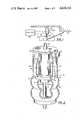
- FIG. 2is a perspective view, with portions broken away, of a preferred embodiment of the combined shock absorber/air spring unit of the suspension system of FIG. 1;
- FIG. 3is a schematic diagram of the combined shock absorber/air spring unit of FIG. 2;
- FIG. 4is a basic block diagram of the control system of this invention.
- FIG. 5shows the inputs and outputs for one suspension unit
- FIG. 6is a block diagram of the processing modules with their inputs and outputs
- FIG. 7is a detailed block diagram for the processing module of a single suspension unit
- FIG. 8is a simplified definitional diagram of a shock absorber
- FIG. 9is a graphical representation of roll control for a predetermined segment of time
- FIG. 10is a diagram for the forces, positions and velocities involved in the topping out and bottoming out control functions
- FIG. 11is a block diagram of one form of the control system of the invention as applied to the structure of FIGS. 2 and 3;
- FIG. 12is an alternative arrangement for a controllable simple shock absorber
- FIG. 13is another alternative embodiment similar to FIG. 12 but with a higher performance shock absorber.
- a wheel 10is rotatably mounted on an axle 11 which extends from one end of a carrier 12.
- the other end of the carrieris pivotally mounted to the frame or chassis and body 14 of the vehicle.
- a suspension unit 16is connected between chassis 14 and axle 11.
- Unit 16combines an upper shock absorber 18 and a lower spring 20, which could be an air spring.
- the wheel, axle and carrierthus comprise the unsprung portion of the vehicle and the frame and body comprise the sprung portion of the vehicle.
- the damping forces of shock absorber 18 and the forces exerted by air spring 20are varied by a control 22 in order to optimize the ride and handling characteristics of the vehicle under a wide range of driving conditions.
- shock absorber 18 and air spring 20 of the suspension unitare arranged in series for simultaneous compression and rebound along the same longitudinal axis as the wheel of the vehicle moves up and down with respect to the frame.
- the shock absorber piston rod 24extends axially through the center of air spring 20 and is connected to the axle of the wheel.
- the air springis typically made of a flexible bellows.
- a connecting member 26extends from the upper end of shock absorber 18 and is attached to the vehicle frame. The lower end of the air spring and rod 24 are interconnected in a known manner so that they move together.
- An air tight cylindrical housing 28concentrically surrounds shock absorber 18. During compression and rebound of air spring 20, air flows between the interiors of the air spring and housing 28 through a vent hole 30 in base 32 of the housing. This air flow helps dissipate heat from the shock absorber. The size of the vent hole and air space in housing 28 will affect the dynamic spring constant of air spring 20. Hydraulic fluid may be filled or drained from shock absorber 18 by removing a fill plug 34 which normally seals a passage that extends from the shock absorber through base 32 of the housing.
- housing 28Within housing 28 are mounted a hydraulic compression pressure regulator 36 and a hydraulic rebound regulator 38. Also mounted within housing 28 are an air pressure inlet valve 40 and an air pressure outlet valve 42. An air inlet nipple 44 and an electrical connection jack 46 are provided on or adjacent upper cap 48 of the housing. An air outlet nipple 50 is provided on base 32 of housing 28. A resilient bump stop 25 is provided to protect the suspension on severe bumps.
- Shock absorber 18includes an inner cylinder 52 and an outer cylinder 54 which surrounds the inner cylinder and defines a reservoir 56.
- a main piston 58is connected to the upper end of piston rod 24 and reciprocates longitudinally within inner cylinder 52.
- Piston 58divides inner cylinder 52 into an upper chamber 60 and a lower chamber 62.
- Inner cylinder 52 and reservoir 56 of the shock absorber and all passages and chambers connected theretoare filled with a quantity of hydraulic fluid. There is no gas in contact with or in the fluid.
- Piston 58is slidable along the upper end of piston rod 24 between a pair of fixed flanges 64 and 66 and is centered between the flanges by springs 68 and 70. This resilient mounting of main piston 58 relative to piston rod 24 cushions any abrupt stops or starts of the piston, thereby eliminating the need for bleed valves in the main piston which are found in conventional shock absorbers. No fluid is intentionally allowed to pass between chambers 60 and 62 through piston 58.
- Shock absorber 18is further provided with a compression amplifying valve 72 which is mounted above upper chamber 60.
- the function of the valve 72is described hereafter in greater detail. It includes a central flanged spool 74 and an outer flanged spool 76 which reciprocates about spool 74. The reciprocation of these spools is limited by springs 78, 79 and 80.
- a hydraulic position sensor 82communicates with reservoir 56 of the shock absorber. It includes a piston 84 which is moved by fluctuations in the amount of hydraulic fluid within cylinder 52 due to the volume occupied by piston rod 24. Position sensor 82 also includes a transducer such as a linear variable differential transformer 86. This transducer generates signals representative of the position of piston 84 and therefore the position of main piston 58. It is clear that with the position of piston 58 known, the instantaneous relative positions of the sprung and unsprung masses are known.
- Compression and rebound pressure regulators 36 and 38may each comprise linear servo solenoid actuated valves. Signals may be applied to these solenoids to adjust the threshold blow off pressure required to open passages 37 and 39 held closed by respective solenoid pistons 85 and 87. This provides a pressure regulator whereby predetermined pressures within chambers 61 and 62 can be independently selected by valves 36 and 38, respectively. Fluid flow will be blocked until pressure reaches the preselected threshold pressure, at which time the valve opens and attempts to maintain that pressure.
- air pressure inlet and outlet valves 40 and 42may each comprise solenoid actuated valves. Signals may be applied to these solenoids to meter the flow of air therethrough.
- the function of air pressure inlet and outlet valves 40 and 42is to adjust or regulate the air pressure within air spring 20.
- the control circuitapplies signals to the solenoids of these valves to meter the flow of air into and out of housing 28. This also adjusts the air pressure within air spring 20 since the air can flow from within the housing and into the air spring through vent hole 30.
- Air pressure inlet valve 40is connected to a pressurized gas source, such as an accumulator 94 which is in turn connected to a pump 96.
- a pipe 98connects the accumulator with inlet nipple 44.
- This nipplecommunicates with valve 40 through a passage 100 in cap 48.
- Air pressure sensors 99 and 101generate signals representative of the air pressure within accumulator 94 and air spring 20, respectively.
- Outlet orifice 102 of valve 40communicates with the interior of the housing.
- Inlet orifice 104 of air pressure outlet valve 42also communicates with the interior of housing 28.
- Passage 90 formed in base 32 of the housingconnects the outlet of valve 42 to outlet nipple 50.
- Passage 98communicates the air pressure in accumulator 94 with all of the suspension units associated with the different wheels of the vehicle.
- Various passagessuch as 88 for hydraulic regulator 36 and 90 for outlet valve 42, which connect the aforementioned regulators and valves to their fluid inputs and outputs, are formed in base 32 and cap 48 of housing 28.
- the leadssuch as 92 of the various solenoids are connected to control 22 via electrical connector 46 (see FIG. 2).
- the controlapplies signals to the solenoids of regulators 36 and 38 to independently adjust the pressure of the hydraulic fluid in upper chamber 61 and in lower chamber 62 to provide predetermined compression and rebound damping forces.
- the pressure in chamber 61sets the threshold pressure in chamber 60 by way of the pressure amplifying valve 72 to be described later.
- the term "signals"will be used to include electrical signals or any other type which may be used to transfer information from one place to another in this system.
- suspension unit 16(FIGS. 2 and 3) can now be described.
- air spring 20When the unit undergoes compression and piston rod 24 moves upward, air spring 20 is compressed and energy is stored therein.
- the pressure of the hydraulic fluid in chamber 60increases as much as pressure regulator 36 allows via amplifying valve 72. This determines the compression damping forces.
- air spring 20expands releasing the stored energy.
- the pressure of the hydraulic fluid in chamber 62increases as much as regulator 38 allows. This determines the rebound damping forces.
- Hydraulic fluidcompletely fills chambers 60 and 62 as well as reservoir 56, the valves of regulators 36 and 38 and the passages leading to and from these valves. Hydraulic fluid also fills passage 106 leading to postion sensor 82.
- the housings of sensor 82 and valves 36 and 38have vent holes 108 to permit the pressurized air which is within air spring 20 and housing 28 to act on sides 85a and 87a of pistons 84, 85 and 87, respectively.
- the hydraulic fluidacts on the fluid side of the pistons 84, 85 and 87, respectively. In this way, the shock absorber adds to the spring rate of the air spring due to its pressure on the fluid within the shock absorber.
- pistons 84, 85 and 87provide a pressure bias to the hydraulic fluid which aids in preventing the formation of gas bubbles or cavitation in the hydraulic fluid during reciprocation of the piston.
- a spring 400can also be provided which acts on side 84a of piston 84 and adds to the pressure bias on the hydraulic fluid (FIG. 3).
- the lack of a spring on pistons 85 and 87 of the solenoidscan be overcome by providing for the fluid in communication with the reservoir 56 to completely surround the pistons 85 and 87 including the portions within the electrical coils (85a, 87a). Otherwise, an appropriate bias spring can be added to the pistons 85 and 87 to balance the fluid pressure resulting from spring 400.
- position sensor 82provides signals to control 22 by means of leads 83 indicating the position of main piston 58 within the shock absorber.
- the controluses this position information to adjust regulators 36 and 38 as necessary to achieve predetermined compression and rebound damping forces.
- hydraulic fluidis pumped from upper chamber 60 of the shock absorber, through amplifying valve 72 via passage 114 or 115 or both, and the valve of regulator 36 and into reservoir 56.
- hydraulic fluid from the reservoiris drawn through check valves 111 and into lower chamber 62 of the shock absorber.
- the amount of fluid which is pumped from upper chamber 60 and the amount of fluid which is pumped into lower chamber 62 during compressionis not equal. This is because of the volume occupied by the portion of piston rod 24 which is progressively inserted into lower chamber 62 during compression.
- the extra hydraulic fluidmoves piston 84 of the position sensor downwardly.
- Compression pressure regulator 36cannot adequately control exceedingly low compression forces which may be required in upper chamber 60, because orifice 37 is too small for the amount of fluid that must flow from chamber 60 into reservoir 56 during rapid movement of piston 58. Therefore, compression amplifying valve 72 enables low compression damping forces to be generated, by providing sufficient orifice size for large flow rates at low compression damping forces, as may be desired. In addition, exceedingly high compression forces can be provided by the compression amplifying valve at all flow rates.
- Compression amplifying valve 72operates as follows. As piston 58 starts to move upward, the pressure of the hydraulic fluid within chamber 60 increases. Spring 79 keeps spool 74 against orifice 115 for a minimum pressure in chamber 60. Hydraulic fluid is forced through an orifice 114 and check valve 116 in flanged spool 74 into upper chamber 61. The pressure within chamber 61 is adjusted by compression pressure regulator 36. If the pressure in chamber 61 is minimal, spool 76 rests against seal 117, and spool 74 rests against seat 112. As the velocity of main piston 58 increases, pressure builds up against the flange of spool 74. Spring 79 determines the blow-off force required to displace spool 74 upwardly. As spool 74 blows off, spring 80 is compressed.
- spool 76As regulator 36 increases the pressure in upper chamber 61, spool 76 is pushed downwardly against springs 78 and 80.
- the force which pushes spool 76 downwardlyis significantly greater than the force which pushes spool 74 upwardly, if chambers 60 and 61 are at similar pressure. This is because the area of the flange of spool 76 is significantly greater than that of spool 74.
- the compression of springs 78 and 80increases the force required for blow-off of spool 74 in such a manner as to set the threshold blow-off pressure in chamber 60 via spool 74 to that of chamber 61 plus the preset bias pressure set by spring 79.
- the rebound pressure regulatordoes not require the amplifying valve because the rebound speeds are more consistent since they deal primarily with the natural frequency of the unsprung mass. This can be adequately controlled by selection of the fixed size of passage 39 in combination with the variable threshold pressure set by pressure regulator 38.
- the rebound forcesact differently on the chassis as affecting passenger comfort in such a way as to allow larger forces in rebound without affecting comfort the way that similar compression forces would.
- FIG. 4represents a typical four-wheeled vehicle showing four controllable suspension units 202, 204, 206 and 208 in communication with central processing unit 210.
- Each suspension unitmay be of the form of FIGS. 2 and 3 or any other suitable controllable device. Note that there are input and output lines between each suspension unit and the central processing unit. The function and operation of each of these blocks will be discussed in greater detail below.
- the block diagram of FIG. 5represents one of the suspension units of FIG. 4 having four input signals and two output signals.
- F Cis the control signal for setting the desired compression damping force
- F Ris the control signal for setting the desired rebound damping force of the suspension unit.
- Each damping forceis substantially independent of the motion (velocity) of the axle with respect to the chassis. Stated another way, damping forces as controlled by this invention are substantially independent of velocity.
- the spring rate inputsof course apply to suspension units having controllable springs such as shown in FIGS. 2 and 3.
- the inputs SR I and SR Dare signals that control the increase or decrease, respectively, of the spring rate.
- On the output side of suspension unit 202 of FIG. 5is the signal P representing the position of the axle with respect to the chassis.
- the K outputis a signal representative of the spring rate which relates to the air pressure of the air spring.
- the processing system of the present inventionis shown in greater detail in FIG. 6. It is important to note that the position (P) and spring rates (K) for all of the suspension units are provided to a processing module associated with each suspension unit.
- Each processing module 212, 214, 216 and 218has four outputs which are the inputs to each suspension unit described above with reference to FIG. 5. These four outputs set the desired spring rate and compression and rebound damping forces in real time for optimum control and performance of each of the suspension units independently but as a total composite to provide for the desired ride characteristics of the vehicle. Even though each suspension unit is independently controlled by the processing modules within the central processing unit, inputs from each suspension unit to each independent processing module ensures that the composite ride of the vehicle is controlled
- FIG. 7is a detailed block diagram of the processing being performed by each processing module associated with each suspension unit. In effect, the FIG. 7 diagram is equivalent to one processing module of FIG. 6.
- the processing represented by FIG. 7is the heart of the ability to optimally control the suspension system.
- the nine basic parameters of vehicle motion that are to be controlled and the manner in which they can easily be simultaneously and optimally combinedare shown in FIG. 7. It is possible that more than nine parameters may be involved, or less for certain applications.
- each of the nine dynamic characteristic detection blocks of the vehiclehave one or more output parameters representative of (PRO) that motion as affecting the desired response of that particular suspension unit.
- PROroll detection algorithm
- the output of DA 242is a parameter representative of roll (PRO ROLL) which is then acted upon by further processing blocks (244) that determine the desired damping and spring rates required to control those particular states of motion.
- the desired responses to correct for roll (DR ROLL)are F C1 and F R1 . This can be done by predetermined mathematical equations or by means of a stored digital memory table look-up, either determined and set by the manufacturer to provide the right control determined during testing of a vehicle, or by analysis.
- Each compression and rebound damping force desired for each motionis added together to give a composite and simultaneous resulting pair of compression and rebound damping forces desired by that suspension unit, thus providing the optimum control and response. This is because the summation of the individually required control forces ( ⁇ F C i and ⁇ F R i ) yields the total desired result in control forces with minimal degradation of individual desired results.
- the height control or load leveling functionhas two parameters representing states of motion. One indicates the condition of the road surface (PRO SURFACE), that is, smooth or bumpy, and the other indicates the average height of the vehicle above the road surface (PRO HEIGHT). Together, the desired response can be determined in such a way as to automatically lower the vehicle for better aerodynamics on smooth roads such as freeways or raise it to go over bumpy roads more easily by allowing more chassis clearance above the road surface, thus providing an automatic adaptive load leveling function. Under normal conditions it would be preferable to raise the chassis quickly when a bumpy surface is encountered, and lower it relatively slowly for a smooth surface aerodynamic advantages.
- the signals F C and F R of FIG. 7are representative of the desired compression and rebound damping forces as described above. If the suspension units utilize signals that correspond almost directly to the desired damping forces, such as the damping device shown in FIGS. 2 and 3, then those F C and F R outputs are usable to control that damping device directly through the appropriate interfaces.
- Position parameter Pis the instantaneous distance between the mounts 230 and 232 of shock absorber 234. Compression forces result from a reduction in the value of P as the vehicle wheel moves toward the chassis, indicated by the upwardly directed arrow F C , and rebound forces act in the opposite direction as the wheel moves away from the chassis, represented by downwardly directed arrow F R .
- FIG. 8Graphic illustrations of terms used in algorithms set out elsewhere in this description are shown in FIG. 8. The difference from the normal mid-range of piston travel is ⁇ D. The instantaneous position P ABS is given by
- P OFFSETis the distance between the chassis mount and the mid-range of piston travel and is a constant, while P ACT is the actual position of the piston.
- the preferred embodiment of this invention as described hereinis substantially velocity independent with respect to the motion of the damping device, that is, the motion between the axle and the chassis.
- the control system of this inventionis adaptable to a velocity dependent suspension system. If the damping device has signal inputs that do not directly control the damping forces, but are dependent on other conditions, then a conversion must be made. For example, if the damping device involves velocity dependance, such as a situation resulting from incorporation of a servo-valve which controls the orifice size for control of the hydraulic fluid flow, then the damping force is dependent upon both the position signal and the velocity of the axle with respect to the chassis. In that case, for any desired force, the proper signals must be translated for any given velocity at that instant.
- the damping force resulting from hydraulic fluid flow through an openingis primarily a function of the size of the opening and the flow rate. If the size of the opening is set by the signal and the flow rate is fixed by the velocity of the shock absorber piston then, if the desired force and the piston velocity are known, there is a direct relationship to the desired signal (opening size) and it can be easily computed.
- control signalswill be changing very rapidly with changing velocity and the damping device must also be able to respond with appropriate speed.
- this translationmay be desired in the damping device that is substantially independent of velocity (the structure of FIGS. 2 and 3) to further optimize the control function.
- Unsprung Massthe wheel and axle supported by the road surface and free to move (unsprung) with the road variations.
- “Spring”an energy storage device which allows movement between chassis and wheel of the vehicle for maintaining an average force that determines the average height of a chassis above the ground.
- Air Springa spring or energy storage device in which a flexible container holds air under pressure and attempts to change its size or length resulting in less space for the air and a corresponding increase in the pressure resulting in an increase in force. Hence it provides a spring rate that is adjustable by changing the initial air pressure and through the design of its shape.
- Spring Ratethis refers to the change in force of the spring per unit length of travel in pounds per inch when it is compressed. If offers stiffness to suspension movement so that higher rates means better control but a harsher ride.
- Stress Absorbera damping device that helps to control the dynamic motions of the spring, wheels and chassis but generating resistance to relative motions of the chassis and wheel through dissipation of energy by means of hydraulic fluid flow through a system of valves and orifices.
- Compression Force (F C )the resistance to movement (pounds force) that the shock absorber produces when the wheel is moving toward the chassis.
- Rebound Force (F R )the resistance to movement (pounds force) that the shock absorber produces when the wheel is moving away from the chassis.
- Rollrefers to the tilt sideways of a vehicle when cornering.
- Pitchrefers to the tilt forward or backward when a vehicle is breaking, cornering or accelerating.
- “Sprung Natural Frequency (SNF)”refers to the tendency of the sprung mass to oscillate on the springs when started in motion. The spring rate and vehicle weight determines the natural frequency of motion, typically about 1 Hz.
- Unsprung Natural Frequency(UNF): this refers to the tendency of the unsprung mass to oscillate between the springs and the road surfaces when started in motion.
- the spring rate and the wheel and axle weightdetermine the natural frequency of motion and are typically about 15 Hz.
- Stored Energythe energy stored in a spring when compressed.
- SEStored Energy
- a suspension springwhen it has been compressed beyond its normal position, such as when a vehicle enters a steep driveway.
- the wheelscompress upward toward the chassis when hitting the ramp and release that energy by causing the front of the vehicle to rise sharply and then rock up and down back to its normal position.
- Peak Downrefers to a situation when the shock absorber compression forces during rapid wheel movements are less than the rebound forces such that the net or total resulting force on the chassis is predominantly downward, thereby overpowering the spring force and pulling the chassis lower to the ground so that there may be insufficient clearance and bottoming out occurs.
- Bottom Outthis refers to the condition where a bump or other influence on the chassis or wheel causes the axle to try to rise toward the chassis closer than it can physically, that is, to exceed the dynamic range of the travel of the suspension. This can cause a severe jolt to the passengers and possibly damage the shock absorber or suspension.
- TOTopping Out
- Air Controlthis refers to the adjustment of the overall average height of a chassis above the road surface. It is accomplished by changing the air pressure in air springs or air pressurized load leveler shock absorbers. Refer to the description of FIG. 8 above.
- P NORMaverage of P ABS long term such as 30 seconds or more (inches)
- P AVEshort term (such as less than 15 seconds) average of P ABS (inches)
- ⁇ P Hheight hysterisis (inches)
- V ABSis P ABS @t-P ABS ⁇ t-1 (inches per second)
- DFTDiscrete Fourier Transform of P ABS giving amplitude of unsprung natural frequency (0 to D inches)
- Parameter with primerefers to opposite side suspension unit from that under control
- Parameter with double primerefers to opposite end suspension unit from that under control
- Parameter with triple primerefers to diagonal suspension unit from that under control
- Parameter with bar overrefers to maximum value desired
- ⁇ P Ris integrated roll position error ( ⁇ 2D inches)
- ⁇ P PDintegrated pumped down position error ( ⁇ D inches)
- Nnumber of bits resolution in a computer word
- a number of variablesare recomputed or modified repeatedly during each successive computer cycle, a cycle being defined as the complete execution of all of the program algorithms. These cycles will be performed about 250 times per second. Each cycle will generate some new values and modify some previous values of the variables, then determine the desired composite compression forces, rebound forces and spring rates for all of the suspension units. These desired values would then be output to the suspension units and held constant until the following cycles modify them on a continuous basis.
- a vehicle of three or more wheelsis subject to roll when it leans to the left or right such as during cornering or when subjected to cross winds.
- the detection algorithms (DA)are based on the natural frequency of the sprung mass. Approximately 100 ms integration of the actual position with respect to the chassis is accomplished for all of the wheels. The difference between these integrated values for the particular suspension unit under analysis and the one on the opposite side indicates a roll condition. The determination of roll is done by comparing front right to front left for the parameter representative of front right roll and front left to front right for the parameter representative of front left control. This processing is repeated in the same way for the rear.
- the integrationaverages out rapid changes in position, such as during rapid bumps, and only changes in position at the natural frequency of the sprung mass are detected.
- the desired response (DR) for the suspension systemis to reduce the amount of roll to which the chassis is subjected. If an axle is moving up toward the chassis due to roll, the compression damping force is raised accordingly to limit this condition as it occurs. Likewise, if the axle is moving away from the chassis, the rebound force is raised accordingly to reduce this condition. Combined, two opposite axles being controlled in this manner offer counter forces to those causing the roll condition, thus greatly reducing the roll that would normally occur. This example is for the left front wheel only.
- the inputs to the detection algorithm portion of the processing module, ROLL DA block 242,are P ABS and P' ABS .
- P ABSis the position P of the left front wheel provided by the position sensor and P' ABS is the position P of the right front wheel provided by the position sensor.
- Position Pis the value P shown in FIG. 5.
- the range of the inputsis ⁇ D inches and the resolution of these inputs is -2 N-1 to +2 N-1 steps at D/2 N-1 inches per step.
- the intermediate equationsare as follows:
- ROLL DA block 242The output of ROLL DA block 242 is ⁇ P R , the parameter representative of roll (PRO ROLL). This becomes the input to the ROLL DR block 244 which must determine the desired response for that roll condition.
- the outputs of the processing module, ROLL DR block 244,will preferably be determined from a look-up table in the processor memory and will be F C1 and F R1 .
- the range of the outputwill be 0 to F C1 (maximum valuue) for F C1 , 0 to F R1 (maximum value) for F R1 and -2D to +2D for ⁇ P R .
- the resolution of the outputswill be: (1) 0 to 2 N-1 steps at F C1 /2 N-1 pounds per step for F C1 ; (2) 0 to 2 N-1 steps at F R1 /2 N-1 pounds per step for F R1 ; and (3) -2 N to +2 N steps at 2D/2 N inches per step for ⁇ P R .
- P ABSis assumed to vary ⁇ 3 inches with 0 inches being the approximate normal position when the vehicle is resting at its desired height on a flat surface
- P NORMis the long term average of P ABS over about a 30-second period.
- the procedure for this stepis that P NORM is assumed to be 0, since the vehicle has been travelling straight over a road surface with any bumps being averaged out, indicating that its desired height that was set by the height control function has remained constant over long periods. If this were not the case, the vehicle would be moving into the air or into the ground, conditions which are not permitted.
- the height control functionmay vary the value of P NORM , but the following algorithms compensate for this automatically and still provide the desired function.
- the applicable computations for Step 1are:
- Step 3Computation of P.sub. ⁇
- Step 4Computation of P'.sub. ⁇
- Step 5Computation of ⁇ P ABS R
- ⁇ P ABS Rapplies to the left front wheel but it is derived from information about both front wheels. Since P'.sub. ⁇ for the opposite side is subtracted from P.sub. ⁇ for the wheel under control, the result indicates the direction and amount of roll that affects the left front wheel. Note that P ABS and P' ABS are changing with each computer cycle as the wheel moves. Therefore, P.sub. ⁇ and P'.sub. ⁇ are also changing. For this reason, ⁇ P ABS R only indicates the possible direction of roll at that particular time t. The road surface irregularities at each cycle could indicate different roll conditions.
- Step 6Computation of ⁇ P R
- ⁇ Ris the predertermined constant of integration that determines the response of the filter (integration); t refers to time as indicated by one of the computer cycles and t-1 is the previous computer cycle; ⁇ P R is the parameter indicating the direction and extent that the vehicle is actually rolling as extracted frrom ⁇ P ABS R .
- the integration equations employed for this steprequire a decision as to whether the instantaneous roll indication ( ⁇ P ABS R ) is greater or less than the previously computed actual roll indication ( ⁇ P R ). If roll is indicated to be greater than the previous value of actual roll ( ⁇ P ABS R > ⁇ P R @t-1), then the integration constant ( ⁇ R ) is added to increase the estimate of actual roll.
- Step 7Computation of F C1 and F R1
- ⁇ P Ris continuously revised and always returns to 0 inches when the vehicle is not subject to roll. That is, for roll control, the algorithm keeps providing damping forces to counteract roll forces as they occur, and no forces when the vehicle is level, as desired.
- ⁇ P Ris essentially a form of real time integration of a time-varying function that detects slow positional changes.
- the update period and the value of ⁇ Rset the bounds on the rate that position changes are detected. This allows the computer to ignore rapid variations such as bumps and holes. Since it is known that the natural frequency of the sprung mass limits the rate at which the chassis can roll, a proper choice for ⁇ R and cycle time can be determined, despite rapid momentary fluctuations of the wheel due to road surface conditions.
- FIG. 9A graphical demonstration of roll control is provided by FIG. 9. It is assumed that the vehicle is following a straight path and then is going into an S curve with a right turn followed by a left turn. It is also assumed that the road is relatively bumpy. Without rigorous calculations, using the above algorithms as described, a graphical representation of the variations of P.sub. ⁇ , P'.sub. ⁇ , ⁇ P ABS R and ⁇ P R are shown, along with the resultant F C1 and F R1 signals. If the whole process of travelling through the curves took 5 seconds, the above algorithms would have been repeated 250 ⁇ 5 or 1,250 times. This graphical example shows the general process that would occur in such a hypothetical case. It should be remembered that this example is for left front wheel roll control only and it does not incorporate other parameters nor does it refer to the control of the other wheels.
- pitchhas been previously defined and applies to a vehicle with two or more wheels when it leans forward or backward as in braking, acceleration or cornering.
- the detection algorithms and desired responseare substantially the same as for roll control except that the front wheel is compared to the rear wheel on the same side instead of being compared with the opposite wheel on the same end.
- the inputs to the processing module PITCH DA block 246are P ABS and P" ABS .
- the range of the inputsis ⁇ D inches and the resolution of these inputs is -2 N-1 to +2 N-1 steps at D/2 N-1 inches per step.
- the intermediate equationsare as follows:
- ⁇ P Pis the output of PITCH DA block 246 going into PITCH DR block 248; which must determine the desired response for the pitch condition.
- the outputs of the processing module PITCH DR block 248will preferably be determined from a look-up table in the processor memory and will be F C2 and F R2 .
- the range of the outputwill be 0 to F C2 (maximum value) for F C2 , 0 to F R2 (maximum value) for F R2 and -2D to +2D for ⁇ P P .
- the resolution of the outputswill be: (1) 0 to 2 N-1 steps at F C2 /2 N-1 pounds per step for F C2 ; (2) 0 to 2 N-1 steps at F R2 /2 N-1 pounds per step for F R2 ; and (3) -2 N to +2 N steps at 2D/2 N inches per step for ⁇ P P .
- Pitch controlis handled almost identically with that of roll control except that the differences are measured between front and rear wheels, that is, in braking the left front wheel moves closer to the chassis while the left rear wheel moves farther from the chassis.
- a different constant of integration, ⁇ Pis used but otherwise the procedure is the same as that for roll control with each individual suspension unit being processed appropriately.
- the detection algorithms PITCH DA block 246provides the parameter representative of pitch to desired response block 248 (PITCH DR) which determines the damping forces necessary (F C2 and F R2 ).
- the inputs to the processing moduleare P ABS , P' ABS , P" ABS and P"' ABS .
- the range of the inputsis ⁇ D inches and the resolution of these inputs is -2 N-1 to +2 N-1 steps at D/2 N-1 inches per step.
- the intermediate equationsare as follows:
- the output of the processing modulewill preferably be determined from a look-up table in the processor memory and will be F C3 , F C4 , F C5 , F C6 , F R3 , F R4 , F R5 and F R6 .
- the resolution of the outputswill be: (1) 0 to 2 N-1 steps at F Ci /2 N-1 pounds per step for F Ci ; (2) 0 to 2 N-1 steps at F Ri /2 N-1 pounds per step for F Ri ; and (3) -2 N-1 to +2 N-1 steps at D/2 N-1 inches per step.
- the detection algorithmcould be a Discrete Fourier Transform Analysis, a well-known mathematical principle. However, it is desired that only one cycle of oscillation be permitted and therefore, a direct look at the position and movement of the axle with respect to the chassis is most desirable. This will indicate if the sprung mass is oscillating.
- the response desired for this parameteris that the suspension unit under analysis be controlled by applying a rebound force as it is compressed sp that it will return to its equilibrium position, but the rate of return will be slowed and some of the stored energy will be dissipated in the flow of hydraulic fluid through the valves. Likewise, as the spring is extended, the compression force is applied to slow the rate of return and dissipate the stored energy.
- the sprung natural frequency control processcorresponds only to the suspension unit under control. If the axle and wheel corresponding to this unit is pushed upward above normal by a rise in the road surface, the compressed spring that exerts an upward force on a chassis will tend to cause the chassis to rise up at its natural frequency and potentially oscillate up and down. By applying a counteracting positive rebound damping force proportional to the amount of spring compression and spring rate, this oscillation can be effectively damped. In other words, the combination of the increased upward spring force and counteracting rebound damping force result in a near neutral force upward on the chassis, consequently preventing any sprung natural frequency oscillations and providing a level and smooth ride. A predefined amount of spring force will always be allowed to remain in order to allow the chassis to recover or return to its proper normal position within a desired amount of time, that is, the rebound damping does not effectively lock the spring at some compressed position.
- the computation look-up tables for compression and rebound damping forcesinclude a negative force in addition to a positive force, which is proportional to the spring compression. This is provided to allow for the additional upward force caused by the spring compression when summing the desired compression forces on the other control functions such as roll, pitch, etc.
- roll controlhas determined the need for 100 lbs of compression force and the sprung natural frequency indicates that the spring is contributing an additional upward force of 100 lbs due to compression, the two will mathematically cancel for an optimum net composite upward force on the chassis at the end of the computer cycle.
- a spring extension below normalsuch as when the wheel drops onto a lowered road surface or into a hole, is similarly handled with a positive compression force to compensate for the loss of upward spring force, and a negative rebound force to counteract other required rebound forces as similarly described for a bump.
- stored energyis the difference between the compressed force for equilibrium and the actual compressed force, and its effect on the sprung mass. For example, if a point on a vehicle is compressed down, it will tend to rise back up and, if raised, it will tend to drop back down. These forces act on the vehicle as a whole. Thus, if the front wheels are compressed upward by a bump, the rear of the vehicle will tend to move downward due to the resulting torque about the center of gravity of the vehicle. Therefore, all of the suspension units controlled by this invention must be considered as to their position relative to the equilibrium position.
- the conditionscan be determined easily by comparing the change in position of the axle with respect to the chassis with the position at equilibrium.
- the stored energy control processis included in this control system to handle forces on the suspension unit under control due to spring forces imposed on the rest of the chassis caused by road conditions.
- the operationis similar to attempting to maintain constant forces on the chassis, only the compression and rebound damping forces must act in opposite directions to counteract the forces on the chassis.
- the front of the vehiclehits a rise in the road surface and the front springs are compressed, their upward force will tend to apply a torque to the vehicle tending to compress the rear springs.
- the proportion of compression on the front springswill result in increased damping force to counteract this torque and prevent the rear from sinking.
- the stored energy and sprung natural frequency control functionstend to control the forces that act on a chassis due to road surface variations compressing and extending the spring and consequently applying forces to the chassis that would normally tend to move the chassis off its desired level ride. It should be noted that since the spring rates may vary due to level control for varying loads, the spring rate inputs may be used to modify the effective spring displacement so that optimum counteracting forces can be applied at all times. For the purposes of further illustration, tables IV-VII show the range of outputs for these two parameters.
- the detection algorithmsinvolve a short term integration (about 3 seconds) of the position of the axle with respect to the chassis and that is compared to the long term average (about 30 seconds) to detect if the position is pumping down.
- the responseis that as the suspension unit starts to pump down, the compression force is correspondingly increased to balance the damping and limit the amount of pumping down that can occur.
- the input to the processing moduleis P ABS .
- the input rangeis ⁇ D inches and the resolution of the input is -2 N-1 to +2 N-1 steps at D/2 N-1 inches per step.
- the intermediate equationsare as follows:
- the outputs of the processing modulewill preferably be determined from a look-up table in the processor memory and will be F C7 and F R7 .
- the range of the outputswill be 0 to F C7 for F C7 , 0 to F R7 for F R7 and -D to +D for ⁇ P PD .
- the resolution of the outputswill be: (1) 0 to 2 N-1 steps at F C7 /2 N-1 pounds per step for F C7 ; (2) 0 to 2 N-1 steps at F R7 /2 N-1 pounds per step for F R7 ; and (3) -2 N-1 to +2 N-1 steps at D/2 N-1 inches per step for ⁇ P PD .
- Pumping downis controlled by integrating the average height of a suspension unit over a period of time longer than the natural frequencies of the sprung mass but shorter than the computation of the average height ( ⁇ P PD ). It includes an integration of the change in height computed just as for roll or pitch control, only the actual change in height from normal for any suspension unit under control is used instead of the difference between two suspension units.
- the detection algorithmsemploy Discrete Fourier Transform (DFT) analysis to determine the amplitude of the frequency component at the natural frequency of the unsprung mass.
- DFTDiscrete Fourier Transform
- the desired responseis that oscillations should be critically damped.
- the best approachappears to be to increase compression damping as the oscillation amplitude increases to limit the level allowed and maintain good road traction by allowing easy rebound to keep the wheel on the surface, while preventing the wheel from bouncing off the surface by increased compression damping.
- the input to the processing moduleis P ABS with a range of ⁇ D inches.
- the resolution of the inputis -2 N-1 to +2 N-1 steps at D/2 N-1 inches per step.
- the intermediate equationis a DFT for frequency of the unsprung mass.
- the output of the processing modulewill preferably be determined from a look-up table in the processor memory and will be F C8 .
- the output rangewill be 0 to F C8 (maximum value) for F C8 and 0 to ⁇ D for DFT.
- the resolution of the outputswill be: (1) 0 to 2 N-1 steps at F C8 /2 N-1 pounds per step for F C8 ; and (2) 0 to 2 N-1 steps at D/2 N-1 inches per step for DFT.
- the DFT analysiswill operate in such a manner that each computer cycle would store the instantaneous position of the axle with respect to the chassis and drop an older measurement, the older measurement being an input value of position taken about 32 cycles previously. The computer would then contain the latest 32 position readings at all times. If a DFT is taken each cycle on those points in order to determine the magnitude of any oscillations at or near the natural frequency of the unsprung mass, then that DFT output would represent the magnitude of any unsprung natural frequencies that may be occurring, which is a basic function of a DFT. If compression damping is applied at increasing rates as the natural frequencies are detected, that is, the DFT output, then the energy in the resident system would be effectively dissipated and any wheel hop or loss of control would be substantially reduced or eliminated.
- the effective value of the DFTcould be appropriately modified to compensate for this change in spring rate or natural frequency, based on the spring rate input to the controller.
- the following tableshows the range of outputs for unsprung natural frequency.
- Desired response for bottoming outis that this control function computes the velocity of the axle with respect to the chassis and its absolute position. It has been stated previously that the present system is velocity-independent but it should be noted that because the computer cycles are much faster than physical changes in the automobile, velocity can be computed from position inputs at any time desired.
- a desired response for the bottoming out parameteris that the compression damping force is progressively increased as the suspension unit approaches its minimal length to prevent any damage. The magnitude of the compression force is higher with higher velocity in order to bring the velocity to zero before bottoming out. This increasing force will help lift the chassis so that it can clear obstacles on a rough terrain.
- the desired response for topping outis that the rebound damping force is progressively increased as the suspension unit approaches its maximum length to prevent damage.
- the magnitude of the rebound forceis higher with higher velocity in order to bring the velocity to zero before topping out.
- the input to both processing modulesis P ABS with a range of ⁇ D inches and a resolution of -2 N-1 to +2 N-1 steps at D/2 N-1 inches per step.
- the intermediate equationis
- the outputs of the processing moduleswill preferably be determined from a look-up table in the processor memory and will be F C9 and F R9 .
- the range of the outputwill be 0 to F C9 (maximum value) for F C9 , 0 to F R9 (maximum value) for F R9 and -V ABS to +V ABS for V ABS .
- the resolution of the outputswill be: (1) 0 to 2 N steps at F C9 /2 N pounds per step for F C9 ; (2) 0 to 2 N steps at F R9 /2 N pounds per step for F R9 ; and (3) -2 M to +2 M steps at V ABS /2 M inches per second per step for V ABS .
- This control processindependently increases compression damping as the axle approaches bottoming out and increases rebound damping as the axle approaches topping out.
- the controllermonitors the position and velocity of the axle with respect to the chassis, and increases the compression damping force to whatever level is required to stop the movement before bottoming out can occur. This is of course limited by the design limits of the compression force and in the case of a large bump, it forces the mass of the vehicle up and over the obstacle with a smooth and evenly controlled force.
- Rebound controllikewise increases the rebound damping force to prevent the axle from approaching its maximum extension from the chassis without first bringing it to a stop, also smoothly.
- the diagram of FIG. 10shows the bottoming out and topping out control function dynamics.
- Thisis often referred to as load leveling and is the long term increase or decrease of the spring rate to keep the sprung mass at a desired average height above the road surface. It functions with a controllable spring such as the air spring shown in FIGS. 2 and 3. This function uses the long term average position of the axle with respect to the chassis and the absolute position.
- the algorithm providedallows for adaptive control of the height of each suspension unit so that variations in height between the front and rear of the vehicle can be accommodated for such things as to aid in aerodynamics for fuel economy, or to raise the chassis for improved clearance when going over bumpy roads.
- the desired response of the height control functionis to provide adaptive load levelings so that on smooth roads, such as freeways, the vehicle lowers for improved aerodynamics.
- smooth roadssuch as freeways
- the vehicleWhen a rough road or bumps are encountered, it automatically raises to a height that offers sufficient dynamic range for the bumps.
- the input to the processing moduleis P ABS with a range ⁇ D inches and a resolution of -2 N-1 to +2 N-1 steps at D/2 N-1 inches per step.
- the intermediate equationsare as follows:
- the output of the processing modulewill preferably be determined from a look-up table in the processor memory and will be P H , the desired height.
- the actual outputs SR I and SR Dwill serve to adjust for that height. If P AVE >P H + ⁇ P H , supply pressurized air to air spring until P AVE ⁇ P H , at which time check for P AVE >P H + ⁇ P H before adding further pressure. If P AVE ⁇ P H - ⁇ P H , release air from air spring until P AVE >P H , at which time check for P AVE ⁇ P H - ⁇ P H before releasing air again.
- the outputscan be represented by the following:
- the desired ride height obtained from the look-up table in the processor for a given His processed with hysteresis ⁇ P H so that the control of the spring rate doesn't keep changing too rapidly between increasing and decreasing commands, thereby resulting in smoother control.
- the chassiswill rise up adaptively to accommodate bumps and automatically lower when no bumps are encountered.
- each suspension unithas inputs of a composite F C and F R for each controller cycle time. Most intermediate computations are done once and shared among the suspension units as would be easily perceived from the preceding discussion.
- Each controller update cycle timecomputes the next setting for F C and F R using the tables in memory and summing in accordance with the above equations.
- control 22A preferred embodiment of control 22 will now be described with reference to FIG. 11. The components illustrated within the dotted outlines may be repeated as necessary dependent upon the desired system control.
- This control systemsimultaneously controls all of the suspension units associated with the different wheels of the vehicle and specifically refers to the suspension unit shown in FIGS. 2 and 3.
- the controlincludes a computer 118 such as a microprocessor having suitable RAM and ROM memories coupled to the microprocessor for storing computation information and operational programs, respectively.
- the computerhas input ports 120 connected thereto for receiving signals from various transducers within the suspension units. Referring to FIG. 3, these include the piston position sensors or transducers 82 on each suspension unit and air pressure sensors 99 and 101 on some or all of these suspension units.
- hydraulic sensor 82comprises a transducer
- a signal source 122may be connected to the input of the transducer and the output of the transducer is connected to detector 124.
- Analog to digital converters 126convert the analog signals from the transducers in the suspension units into digital form before they are input to computer 118 through the input ports.
- the microprocessoruses the operational programs stored in the ROM of the computer, the microprocessor continuously determines the optimum compression and rebound damping forces as well as the optimum spring rate. Commands are sent from the computer to control pump 96, air pressure inlet and outlet regulators 40 and 42 on some or all of the suspension units and compression and rebound regulators 36 and 38 on each suspension unit.
- Output ports 128provide the interface between computer 118 and the devices which it controls.
- Digitally controlled switches 130are utilized to turn air pump 96 on and off and to open and close the air pressure valves 40 and 42.
- Digital to analog converters 131, current sources 132 and optional high voltage supply 134are utilized to generate the signals necessary to control hydraulic compression and rebound pressure regulators 36 and 38.
- FIG. 12shows the simplest possible electrically controllable shock absorber.
- Shock absorber 200is that of any conventional design.
- the variationis that the first stage valving or "bleed orificing" includes orifice 406 in a piston 401 which is set for very rapid pressure buildup or may be removed from improved roll control and performance.
- FIG. 12An example of this type of valving is provided in FIG. 12.
- the sectional view of piston 401shows a pair of orifices 402 and 403 extending through piston 401 to provide passageways for hydraulic fluid to flow between compression and rebound chambers during reciprocation by the piston.
- a spring loaded valve 404at the lower opening of orifice 402, when a certain pressure is reached, operates to allow hydraulic fluid to flow through the orifice during compression of the shock absorber but remains closed during rebound.
- a spring loaded valve 405, at the lower opening of orifice 403operates to allow fluid to flow through the orifice when a certain pressure is reached during rebound of the shock absorber but remains closed during compression.
- the diameter of these orificesmay be selected to provide the appropriate valve characteristics. It is to be understood that other conventional high performance valving could also be used in this variation of the invention. For example, the bleed orifice 406 may be eliminated.
- valves in the piston and orifice 406have been described with reference to FIG. 12, these same elements may be employed with the piston 58 and rod 24 in the embodiment of FIG. 3 which includes springs 68 and 70.
- a solenoid pressure regulator valve 220 of the preferred embodimentis connected to the compression chamber by means of conduit 230 and to the rebound chamber by means of conduit 240.
- Control 210which may be either manual or automatic, can be made to set the initial first stage blow off pressure on compression to any level from very little pressure for soft control to very high pressure for stiff control. This is accomplished by allowing valve 220 to bypass the fluid flow around the first stage orificing within shock absorber 200 upon compression.
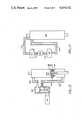
- FIG. 13illustrates a variation that is capable of much higher performance.
- the fluid pressure in chamber 61is obtained by fluid flow through passage 114 due to the bias pressure generated by the action of spring 79 on spool 74. This flow is limited for soft ride characteristics. If chamber 61 is isolated from the fluid in the shock absorber and connected to an external fluid pressure supply as shown in FIG. 13, then faster response may be obtained.
- shock absorber 300is that shown in FIG. 3 but with spring 79 removed and passage 114 blocked.
- Passage 88 in FIG. 3is connected to passage 350 in FIG. 13.
- Passage 89 in FIG. 3is connected to passage 355 in FIG. 13.
- the operation of the system illustrated in FIG. 13is as follows.
- the blow off pressure of spool 74 in FIG. 3is still set by the pressure on chamber 61.
- the fluid pressure in chamber 61is set by valve 36 with the fluid flow into chamber 62 provided through passage 350 from a high pressure fluid accumulator 320 as shown in FIG. 13.
- the return fluid flow from valve 36 in FIG. 3goes to a fluid reservoir 330.
- Pump 330is then connected between accumulator 320 and reservoir 330 by means of passages 340 and 345 to recharge accumulator 320.
- the shock absorber structure and the control connectionswhich may utilize the pressure regulator solenoid valve and amplifying valve in different combinations.
- the amplifying valvecan have spring 80 removed and spools 74 and 76 attached as one unit.
- the main blow off orifice 115would normally be open.
- the larger area at spool 76is attached directly to spool 74 and the blow off flange causes the pressure in chamber 60 to reach a multiple of that in chamber 61 at all times for much higher performance.
- valve 72occurs when amplification is not required.
- spring 78is removed and spool 76 is rigidly attached to the valve body such as at seat 117.
- the surface area of spool 74 facing chamber 61can be made equal to the surface area of spool 74 facing chamber 60. In such case pressure settings in chamber 61 are equal to that in chamber 60 for blowoff conditions at orifice 115.
- any number of parameterscan be accommodated by the system, for example, pumping down may be omitted, or others may be added.
- Position of the main piston in the shock absorberrepresents the position of the axle with respect to the chassis.
- Position output signalsare not necessarily required from every suspension unit of a vehicle, but it is highly desirable that there by position signals from each wheel of a four-wheel vehicle.
- the desired responses programmed in FIG. 7can be determined either from solution of equations or table look-up, with the latter generally being faster.
- Spring rate output signalsmay be from any number of the suspension units, from zero to all the springs.
- the spring rate controlscan be any number, for example both front springs or both rear springs can be controlled together, or all four can be controlled together.
- control algorithmsmay be any type or form desired. Those provided are by way of example and for purposes of completeness of description.
- This systemapplies to any suspension unit capable of having a signal output representing position and being controllable by inputs that control compression and rebound damping.
- the systemprovides the enumerated advantages at relatively low cost and weight, improves aerodynamics with the height control function, adapts for wear automatically, utilizes conventional manufacturing, is highly reliable, employs low (10%) tolerance components and provides a luxury ride simultaneously with high stability performance.
- this control systemprovides a cost effective suspension using microprocessor technology to achieve fundamental suspension control of any vehicle while approaching the theoretical limit of suspension performance and providing near ideal ride characteristics.
Landscapes
- Engineering & Computer Science (AREA)
- Mechanical Engineering (AREA)
- Vehicle Body Suspensions (AREA)
Abstract
Description
P.sub.ABS =P.sub.OFFSET -P.sub.ACT.
P.sub.NORM =Long term average of P.sub.ABS
P'.sub.NORM =Long term average of P'.sub.ABS
P.sub.Δ =P.sub.ABS -P.sub.NORM
P'.sub.Δ =P'.sub.ABS -P'.sub.NORM
ΔP.sub.ABS.sup.R =P.sub.Δ -P'.sub.Δ
ΔP.sub.R @t=ΔP.sub.R @t-1+ΔR(if ΔP.sub.ABS.sup.R >ΔP.sub.R @t-1)
ΔP.sub.R @t=ΔP.sub.R @t-1-ΔR(if ΔP.sub.ABS.sup.R <ΔP.sub.R @t-1)
TABLE I ______________________________________ ΔP.sub.R F.sub.C1 F.sub.R1 ______________________________________ +2D ##STR1## 0 ↑ ↑ ↑ 0 0 0 ↓ ↓ ↓ -2D 0 ##STR2## ______________________________________
P.sub.ABS =+1 inch
P.sub.Δ =P.sub.ABS -P.sub.NORM
P.sub.Δ =+1-0=+1
P'.sub.ABS =-1 inch
P'.sub.Δ =P'.sub.ABS -P'.sub.NORM
P'Δ=-1-0=-1
ΔP.sub.ABS.sup.R =P.sub.Δ -P'.sub.Δ
ΔP.sub.ABS.sup.R =(+1)-(-1)
ΔP.sub.ABS.sup.R =+2 inches
Δ.sub.R =0.5 (constant)
ΔP.sub.R @t=ΔP.sub.R @t-1+ΔR
ΔP.sub.R @t=0+0.5=0.5 inches
TABLE II ______________________________________ P.sub.R F.sub.C1 F.sub.R1 ______________________________________ +2.0 inches 400 lbs. 0 lbs. +1.5inches 300 lbs. 0 lbs. +1.0inches 200 lbs. 0 lbs. +0.5inches 100 lbs. 0 lbs. +0.0inches 0 lbs. 0 lbs. -0.5inches 0 lbs. 100 lbs. -1.0inches 0 lbs. 200 lbs. -1.5inches 0 lbs. 300 lbs. -2.0inches 0 lbs. 400 lbs. ______________________________________
F.sub.C1 =100 lbs
F.sub.R1 =0 lbs
P.sub.NORM =Long term average of P.sub.ABS
P".sub.NORM =Long term average of P".sub.ABS
P.sub.Δ =P.sub.ABS -P.sub.NORM
P".sub.Δ -P".sub.ABS -P".sub.NORM
ΔP.sub.ABS.sup.P =P.sub.Δ -P".sub.Δ
ΔP.sub.P @t=ΔP.sub.P @t-1+ΔP(if ΔP.sub.ABS.sup.P >ΔP.sub.P @t-1)
ΔP.sub.P @t=ΔP.sub.P @t-1-ΔP(if ΔP.sub.ABS.sup.P <ΔP.sub.P @t-1)
TABLE III ______________________________________ ΔP.sub.P F.sub.C2 F.sub.R2 ______________________________________ +2D ##STR3## 0 ↑ ↑ ↑ 0 0 0 ↓ ↓ ↓ -2D 0 ##STR4## ______________________________________
P.sub.NORM =Long term average of P.sub.ABS
P'.sub.NORM =Long term average of P'.sub.ABS
P".sub.NORM =Long term average of P".sub.ABS
P"'.sub.NORM =Long term average of P"'.sub.ABS
P.sub.Δ =P.sub.ABS -P.sub.NORM
P'.sub.Δ =P'.sub.ABS -P'.sub.NORM
P".sub.Δ =P".sub.ABS -P".sub.NORM
P'".sub.Δ =P'".sub.ABS -P'".sub.NORM
TABLE IV ______________________________________ P.sub.Δ F.sub.C3 F.sub.R3 ______________________________________ +D ##STR5## ##STR6## ↑ ↑ ↑ 0 0 0 ↓ ↓ ↓ -D ##STR7## ##STR8## ______________________________________
TABLE V ______________________________________ P'.sub.Δ F.sub.C4 F.sub.R4 ______________________________________ +D ##STR9## ##STR10## ↑ ↑ ↑ 0 0 0 ↓ ↓ ↓ -D ##STR11## ##STR12## ______________________________________
TABLE VI ______________________________________ P".sub.Δ F.sub.C5 F.sub.R5 ______________________________________ +D ##STR13## ##STR14## ↑ ↑ ↑ 0 0 0 ↓ ↓ ↓ -D ##STR15## ##STR16## ______________________________________
TABLE VII ______________________________________ P"'.sub.Δ F.sub.C6 F.sub.R6 ______________________________________ +D ##STR17## ##STR18## ↑ ↑ ↑ 0 0 0 ↓ ↓ ↓ -D ##STR19## ##STR20## ______________________________________
P.sub.NORM =Long term average of P.sub.ABS
P.sub.Δ =P.sub.ABS -P.sub.NORM
ΔP.sub.PD @t=ΔP.sub.PD @t-1+Δ.sub.PD (if P.sub.Δ >ΔP.sub.PD @t-1)
ΔP.sub.PD @t=ΔP.sub.PD @t-1-Δ.sub.PD (if P.sub.Δ <P.sub.PD @t-1)
TABLE VIII ______________________________________ P.sub.PD F.sub.C7 F.sub.R7 ______________________________________ +D ##STR21## 0 ↑ ↑ ↑ 0 0 0 ↓ ↓ ↓ -D 0 ##STR22## ______________________________________
TABLE IX ______________________________________ DFT F.sub.C8 ______________________________________ D ##STR23## ↑ ↑ 0 0 ______________________________________
V.sub.ABS =P.sub.ABS @t-P.sub.ABS @t-1.
If P.sub.Δ (any wheel)>H, then H@t=H@t-1+KΔ.sub.H
If P.sub.Δ (any wheel)≦H, then H@t=H@t-1-Δ.sub.H (H≧0)
P.sub.AVE =Average of P.sub.ABS
TABLE X ______________________________________ H P.sub.H ______________________________________ 0 0 ↓ ↓ +D -D ______________________________________
F.sub.C =ΣF.sub.Ci =F.sub.C1 +F.sub.C2 . . . F.sub.C9
F.sub.R =ΣF.sub.Ri =F.sub.R1 +F.sub.R2 . . . F.sub.R9
Claims (46)
Priority Applications (1)
| Application Number | Priority Date | Filing Date | Title |
|---|---|---|---|
| US06/644,806US4634142A (en) | 1983-08-15 | 1984-08-27 | Computer optimized adaptive suspension system |
Applications Claiming Priority (2)
| Application Number | Priority Date | Filing Date | Title |
|---|---|---|---|
| US06/523,279US4468050A (en) | 1983-08-15 | 1983-08-15 | Computer optimized adaptive suspension system |
| US06/644,806US4634142A (en) | 1983-08-15 | 1984-08-27 | Computer optimized adaptive suspension system |
Related Parent Applications (2)
| Application Number | Title | Priority Date | Filing Date |
|---|---|---|---|
| US06/352,239Continuation-In-PartUS4468739A (en) | 1981-11-17 | 1982-02-25 | Computer optimized adaptive suspension system having combined shock absorber/air spring unit |
| US06/523,279Continuation-In-PartUS4468050A (en) | 1981-11-17 | 1983-08-15 | Computer optimized adaptive suspension system |
Publications (1)
| Publication Number | Publication Date |
|---|---|
| US4634142Atrue US4634142A (en) | 1987-01-06 |
Family
ID=27061094
Family Applications (1)
| Application Number | Title | Priority Date | Filing Date |
|---|---|---|---|
| US06/644,806Expired - LifetimeUS4634142A (en) | 1983-08-15 | 1984-08-27 | Computer optimized adaptive suspension system |
Country Status (1)
| Country | Link |
|---|---|
| US (1) | US4634142A (en) |
Cited By (121)
| Publication number | Priority date | Publication date | Assignee | Title |
|---|---|---|---|---|
| US4685698A (en)* | 1985-05-23 | 1987-08-11 | Daimler-Benz Aktiengesellschaft | Apparatus for the road-surface-dependent control of shock absorbers in a vehicle suspension system |
| US5373445A (en)* | 1992-03-05 | 1994-12-13 | Ford Motor Company | Method and apparatus for determining dynamic force within an air spring suspension |
| US5434782A (en)* | 1991-05-20 | 1995-07-18 | General Motors Corporation | Suspension system state observer |
| US5450322A (en)* | 1990-06-19 | 1995-09-12 | Mitsubishi Jidosha Kogyo Kabushiki Kaisha | Suspension control system for automotive vehicle |
| US5475596A (en)* | 1991-05-20 | 1995-12-12 | General Motors Corporation | Full car semi-active suspension control based on quarter car control |
| US5519612A (en)* | 1991-06-24 | 1996-05-21 | Ford Motor Company | Active suspension system with adaptive actuator gain adjustment |
| US5529152A (en)* | 1994-07-08 | 1996-06-25 | Aimrite Systems International, Inc. | Variable constant force hydraulic components and systems |
| US5559700A (en)* | 1995-03-27 | 1996-09-24 | General Motors Corporation | Continuously variable damping system |
| US5570288A (en)* | 1995-03-27 | 1996-10-29 | General Motors Corporation | Vehicle suspension control using a scaled wheel demand force |
| US5570289A (en)* | 1995-03-27 | 1996-10-29 | General Motors Corporation | Vehicle suspension control with wheel and body demand force phase determination |
| US5606503A (en)* | 1995-03-27 | 1997-02-25 | General Motors Corporation | Suspension system control responsive to ambient temperature |
| US5692587A (en)* | 1995-05-15 | 1997-12-02 | General Motors Corporation | Vehicle chassis system control |
| KR100229527B1 (en)* | 1995-12-26 | 1999-11-15 | 정몽규 | Automatic garage control device of vehicle and its control method |
| EP0921387A3 (en)* | 1997-12-08 | 1999-12-08 | Beissbarth GmbH | Method and device for testing in situ shock absorber |
| EP0921386A3 (en)* | 1997-12-08 | 2000-01-19 | Beissbarth GmbH | Method and device for testing of mounted shock absorbers |
| WO2000028236A1 (en)* | 1998-11-11 | 2000-05-18 | Kenmar Company Trust | Enhanced computer optimized adaptive suspension system and method |
| WO2000040429A3 (en)* | 1999-01-08 | 2000-11-02 | Shockware | Vehicle-mountable, suspension monitoring system |
| US6345705B1 (en) | 2000-04-28 | 2002-02-12 | Philip W. Tremblay | Self-corrective vehicle shock absorber |
| US6398227B1 (en)* | 2000-10-13 | 2002-06-04 | Case Corp. | Ride control apparatus and method |
| US6516257B2 (en)* | 2001-01-03 | 2003-02-04 | Delphi Technologies, Inc. | Method and system for independent axle control of a variable force damper system |
| WO2003045718A1 (en)* | 2001-11-28 | 2003-06-05 | Peugeot Citroen Automobiles S.A. | Method for evaluating instantaneous frequency of a mechanical excitation exerted on a motor vehicle wheel, and applications |
| US20040055795A1 (en)* | 2002-07-12 | 2004-03-25 | Kamen Dean L. | Control of a transporter based on attitude |
| US6732033B2 (en) | 2002-01-11 | 2004-05-04 | Active Shock, Inc. | Semi-active shock absorber control system |
| US20040111707A1 (en)* | 2000-12-15 | 2004-06-10 | Bliss Andrew L. | Debugger for multiple processors and multiple debugging types |
| US20040154887A1 (en)* | 2002-11-27 | 2004-08-12 | Nehl Thomas W. | Suspension control system and related damper with integrated local controller and sensors |
| US20040178587A1 (en)* | 2003-03-14 | 2004-09-16 | Hiebert Grant W. | Electronic suspension and level control system for recreational vehicles |
| US20050242532A1 (en)* | 2004-01-06 | 2005-11-03 | Deo Hrishikesh V | Suspension system with independent control of ride-height, stiffness and damping |
| EP1353836A4 (en)* | 2000-09-25 | 2006-03-22 | Its Bus Inc | Platforms for sustainable transportation |
| US20060060750A1 (en)* | 2004-09-03 | 2006-03-23 | Delphi Technologies, Inc. | Vehicle suspension system and method for operating |
| US20060181034A1 (en)* | 2005-02-17 | 2006-08-17 | Wilde Michael D | Vehicle ride control system |
| US20060237242A1 (en)* | 2000-09-25 | 2006-10-26 | Burke Robert J | Lightweight surface vehicle |
| US20060255623A1 (en)* | 2005-05-13 | 2006-11-16 | Erwin Haller | Device and method for suspension of a vehicle cabin by means of additional volumes |
| US20060267297A1 (en)* | 2005-05-28 | 2006-11-30 | Bfs Diversified Products, Llc | Air spring assembly with localized signal processing, system and method utilizing same, as well as operating module therefor |
| US20070150143A1 (en)* | 2004-03-22 | 2007-06-28 | Continental Aktiengesellschaft | Method for controlling the damper force in vehicles having a ride level control system |
| US20070208484A1 (en)* | 2006-03-06 | 2007-09-06 | Denso Corporation | Vehicle cruise control system and road condition estimating system |
| US7287760B1 (en)* | 2006-08-21 | 2007-10-30 | Bfs Diversified Products, Llc | Vehicle suspension system and method |
| EP1680290A4 (en)* | 2003-10-17 | 2007-11-07 | Active Air Suspension Ltd | Vehicle suspension control |
| US20080051952A1 (en)* | 2006-08-28 | 2008-02-28 | Jungheinrich Aktiengesellschaft | Industrial Truck Control System |
| US7338335B1 (en)* | 2001-01-23 | 2008-03-04 | Frank Messano | Hybrid electric heavy-duty vehicle drive system |
| US20080150202A1 (en)* | 2006-12-18 | 2008-06-26 | Grammer Ag | Air spring for a vehicle seat, and vehicle seat comprising such an air spring |
| US20080215210A1 (en)* | 2005-07-05 | 2008-09-04 | Renault S.A.S. | Anti-Rolling Method and System For a Vehicle and Corresponding Vehicle |
| US20080315539A1 (en)* | 2007-06-21 | 2008-12-25 | Steinbuchel Herman J | Vertical air bag control |
| US20090026816A1 (en)* | 2007-07-14 | 2009-01-29 | Grammer Ag | Vehicle seat with base frame and adjustable seat frame |
| US20090097038A1 (en)* | 2007-10-16 | 2009-04-16 | Higgins-Luthman Michael J | Machine Vision for Predictive Suspension |
| US20090125194A1 (en)* | 2007-10-08 | 2009-05-14 | Grammer Ag | Vehicle comprising a spring-mounted vehicle seat and a spring-mounted vehicle cab, and suspension method |
| US20090134595A1 (en)* | 2007-11-24 | 2009-05-28 | Grammer Ag | Apparatus comprising a suspension system and method for adjusting a suspension system |
| US20090179390A1 (en)* | 2007-12-04 | 2009-07-16 | Grammer Ag | Apparatus and method for active spring suspension of a vehicle component |
| US20090272871A1 (en)* | 2008-05-03 | 2009-11-05 | Grammer Ag | Vehicle seat having a device for controlling a pneumatic suspension system |
| WO2009135670A1 (en)* | 2008-05-07 | 2009-11-12 | Knorr-Bremse Systeme für Nutzfahrzeuge GmbH | Axle assembly and control arm |
| US20090319123A1 (en)* | 2008-06-23 | 2009-12-24 | Gm Global Technology Operations, Inc. | Method and system for detecting a vibration level of a wheel within a resonating frequency range of a vehicle suspension |
| US7661681B1 (en)* | 2008-06-30 | 2010-02-16 | Aspen Custom Trailers | Automated suspension system |
| US20100042291A1 (en)* | 2006-03-22 | 2010-02-18 | Gm Global Technology Operations, Inc. | Method for controlling/regulating an electronically controlled damping system in a convertible motor vehicle |
| US20100102493A1 (en)* | 2008-10-23 | 2010-04-29 | Grammer Ag | Spring-mounted vibration system to reduce vibration |
| US20100117428A1 (en)* | 2008-11-06 | 2010-05-13 | Grammer Ag | Scissors-type frame for a vehicle seat and method for producing a substructure of a vehicle seat |
| US20100181708A1 (en)* | 2009-01-21 | 2010-07-22 | Grammer Ag | Device for springing a mass, and method for adjusting and/or operating a fluid spring |
| US20100213397A1 (en)* | 2009-02-24 | 2010-08-26 | Hadley Products | Height control valve for vehicle leveling system |
| US20100230911A1 (en)* | 2009-03-11 | 2010-09-16 | John Ashley Peterson | Speed dependent control for dual air spring configuration |
| US20100237656A1 (en)* | 2005-05-13 | 2010-09-23 | Grammer Ag | Device and method for suspension of a vehicle cabin by means of additional volumes |
| US20110093239A1 (en)* | 2009-10-21 | 2011-04-21 | Holbrook Gregory A | Vehicle weight sensing methods and systems |
| US8196723B1 (en) | 2008-11-14 | 2012-06-12 | Robust Systems Solutions, LLC | Pneumatic damper |
| USD673886S1 (en)* | 2011-08-08 | 2013-01-08 | Firestone Industrial Products Company, Llc | Gas spring end member |
| USD673887S1 (en)* | 2011-08-08 | 2013-01-08 | Firestone Industrial Products Company, Llc | Gas spring end member |
| USD674325S1 (en)* | 2011-08-08 | 2013-01-15 | Firestone Industrial Products Company, Llc | Gas spring end member |
| US20130103259A1 (en)* | 2011-10-20 | 2013-04-25 | GM Global Technology Operations LLC | Vehicle suspension system and method of using the same |
| US20130144489A1 (en)* | 2011-09-12 | 2013-06-06 | Fox Factory, Inc. | Methods and apparatus for suspension set up |
| US8517396B2 (en) | 2009-06-01 | 2013-08-27 | Firestone Industrial Products Company, Llc | Height control module, gas spring assembly and method |
| US8864145B2 (en) | 2005-05-13 | 2014-10-21 | Grammer Ag | Device and method for suspension of a vehicle seat by means of additional volumes |
| US8868294B2 (en) | 2012-09-28 | 2014-10-21 | Firestone Industrial Products Company, Llc | Adjustable hysteresis circuit for control of air suspension |
| USD746183S1 (en) | 2014-07-09 | 2015-12-29 | Firestone Industrial Products Company, Llc | Gas spring end member |
| US9718323B2 (en)* | 2014-06-13 | 2017-08-01 | Audi Ag | Method for operating a wheel suspension system |
| US10036443B2 (en) | 2009-03-19 | 2018-07-31 | Fox Factory, Inc. | Methods and apparatus for suspension adjustment |
| US10040331B2 (en) | 2016-04-04 | 2018-08-07 | Barksdale Inc. | Ride height leveling with selectable configurations system and method |
| US10040329B2 (en) | 2009-01-07 | 2018-08-07 | Fox Factory, Inc. | Method and apparatus for an adjustable damper |
| US10047817B2 (en) | 2009-01-07 | 2018-08-14 | Fox Factory, Inc. | Method and apparatus for an adjustable damper |
| US10060499B2 (en) | 2009-01-07 | 2018-08-28 | Fox Factory, Inc. | Method and apparatus for an adjustable damper |
| US10072724B2 (en) | 2008-08-25 | 2018-09-11 | Fox Factory, Inc. | Methods and apparatus for suspension lock out and signal generation |
| US10086892B2 (en) | 2010-07-02 | 2018-10-02 | Fox Factory, Inc. | Lever assembly for positive lock adjustable seat post |
| US10094443B2 (en) | 2009-01-07 | 2018-10-09 | Fox Factory, Inc. | Bypass for a suspension damper |
| US10145435B2 (en) | 2009-03-19 | 2018-12-04 | Fox Factory, Inc. | Methods and apparatus for suspension adjustment |
| US10160511B2 (en) | 2009-01-07 | 2018-12-25 | Fox Factory, Inc. | Method and apparatus for an adjustable damper |
| US10315481B2 (en)* | 2015-11-05 | 2019-06-11 | Ford Global Technologies, Llc | Systems and methods for vehicle dynamics assignment |
| US10330171B2 (en) | 2012-05-10 | 2019-06-25 | Fox Factory, Inc. | Method and apparatus for an adjustable damper |
| US10371228B2 (en)* | 2014-09-23 | 2019-08-06 | Borgwarner Inc. | Control strategy for a variable spring rate absorber |
| US10400847B2 (en) | 2009-01-07 | 2019-09-03 | Fox Factory, Inc. | Compression isolator for a suspension damper |
| US10406883B2 (en) | 2009-10-13 | 2019-09-10 | Fox Factory, Inc. | Methods and apparatus for controlling a fluid damper |
| US10414236B2 (en) | 2009-03-19 | 2019-09-17 | Fox Factory, Inc. | Methods and apparatus for selective spring pre-load adjustment |
| US10415662B2 (en) | 2009-01-07 | 2019-09-17 | Fox Factory, Inc. | Remotely operated bypass for a suspension damper |
| US10443671B2 (en) | 2009-01-07 | 2019-10-15 | Fox Factory, Inc. | Remotely operated bypass for a suspension damper |
| US10472013B2 (en) | 2008-11-25 | 2019-11-12 | Fox Factory, Inc. | Seat post |
| US10537790B2 (en) | 2008-11-25 | 2020-01-21 | Fox Factory, Inc. | Methods and apparatus for virtual competition |
| US10677309B2 (en) | 2011-05-31 | 2020-06-09 | Fox Factory, Inc. | Methods and apparatus for position sensitive suspension damping |
| US10697514B2 (en) | 2010-01-20 | 2020-06-30 | Fox Factory, Inc. | Remotely operated bypass for a suspension damper |
| CN111386203A (en)* | 2017-11-28 | 2020-07-07 | 沃尔沃卡车集团 | Method for determining the functional state of a vehicle shock absorber device |
| US10731724B2 (en) | 2009-10-13 | 2020-08-04 | Fox Factory, Inc. | Suspension system |
| US10737546B2 (en) | 2016-04-08 | 2020-08-11 | Fox Factory, Inc. | Electronic compression and rebound control |
| US20200325958A1 (en)* | 2019-04-15 | 2020-10-15 | Integrated Dynamics Engineering Gmbh | Stationary vibration isolation system and control method thereof |
| US10814690B1 (en) | 2017-04-18 | 2020-10-27 | Apple Inc. | Active suspension system with energy storage device |
| US10821795B2 (en) | 2009-01-07 | 2020-11-03 | Fox Factory, Inc. | Method and apparatus for an adjustable damper |
| CN111954601A (en)* | 2018-04-06 | 2020-11-17 | 沃尔沃卡车集团 | Method for determining a desired speed of a vehicle |
| US10899340B1 (en) | 2017-06-21 | 2021-01-26 | Apple Inc. | Vehicle with automated subsystems |
| US10906370B1 (en) | 2017-09-15 | 2021-02-02 | Apple Inc. | Active suspension system |
| US10960723B1 (en) | 2017-09-26 | 2021-03-30 | Apple Inc. | Wheel-mounted suspension actuators |
| US11046143B1 (en) | 2015-03-18 | 2021-06-29 | Apple Inc. | Fully-actuated suspension system |
| US11124035B1 (en) | 2017-09-25 | 2021-09-21 | Apple Inc. | Multi-stage active suspension actuator |
| US11173766B1 (en) | 2017-09-07 | 2021-11-16 | Apple Inc. | Suspension system with locking structure |
| US11179991B1 (en) | 2019-09-23 | 2021-11-23 | Apple Inc. | Suspension systems |
| FR3113129A1 (en)* | 2020-07-30 | 2022-02-04 | Psa Automobiles Sa | Method for predicting the stiffness of a damping system |
| US11279199B2 (en) | 2012-01-25 | 2022-03-22 | Fox Factory, Inc. | Suspension damper with by-pass valves |
| US11285773B1 (en) | 2018-09-12 | 2022-03-29 | Apple Inc. | Control system |
| US11299233B2 (en) | 2009-01-07 | 2022-04-12 | Fox Factory, Inc. | Method and apparatus for an adjustable damper |
| US11306798B2 (en) | 2008-05-09 | 2022-04-19 | Fox Factory, Inc. | Position sensitive suspension damping with an active valve |
| US11345209B1 (en) | 2019-06-03 | 2022-05-31 | Apple Inc. | Suspension systems |
| US11358431B2 (en) | 2017-05-08 | 2022-06-14 | Apple Inc. | Active suspension system |
| US11634167B1 (en) | 2018-09-14 | 2023-04-25 | Apple Inc. | Transmitting axial and rotational movement to a hub |
| US11707961B1 (en) | 2020-04-28 | 2023-07-25 | Apple Inc. | Actuator with reinforcing structure for torsion resistance |
| US11828339B1 (en) | 2020-07-07 | 2023-11-28 | Apple Inc. | Vibration control system |
| US11938922B1 (en) | 2019-09-23 | 2024-03-26 | Apple Inc. | Motion control system |
| US12017498B2 (en) | 2021-06-07 | 2024-06-25 | Apple Inc. | Mass damper system |
| US12122205B2 (en) | 2009-01-07 | 2024-10-22 | Fox Factory, Inc. | Active valve for an internal bypass |
| US12168375B1 (en) | 2023-01-26 | 2024-12-17 | Apple Inc. | Motion control system |
| US12251973B2 (en) | 2022-06-10 | 2025-03-18 | Apple Inc. | Vibration absorber |
Citations (77)
| Publication number | Priority date | Publication date | Assignee | Title |
|---|---|---|---|---|
| US601339A (en)* | 1898-03-29 | Automatic wagon-scale | ||
| US2247749A (en)* | 1937-02-04 | 1941-07-01 | Venel Georges D Espinassy De | Stabilizing device for terrestrial vehicles |
| US2339152A (en)* | 1941-09-09 | 1944-01-11 | John T Connelly | Hydrostatical weighing apparatus |
| FR1079482A (en)* | 1953-06-22 | 1954-11-30 | Hydraulic shock absorber, double acting, self-regulating, with suspension braking, variable and automatic, acting according to the speed and the turning radius of the vehicle or by selective manual control | |
| US2893104A (en)* | 1957-05-23 | 1959-07-07 | Gen Motors Corp | Air suspension |
| US2967062A (en)* | 1956-08-30 | 1961-01-03 | Avigdor Leslie B D | Sway and pitch control apparatus for vehicles |
| US2973969A (en)* | 1955-05-11 | 1961-03-07 | Earle S Thall | Electrical shock absorbing system |
| US2993705A (en)* | 1958-08-18 | 1961-07-25 | Avigdor Leslie B D | Electropneumatic sway control apparatus for land vehicles |
| US3035853A (en)* | 1958-12-10 | 1962-05-22 | Itt | Vehicle suspension and stabilizing system |
| US3063701A (en)* | 1960-08-30 | 1962-11-13 | Gen Motors Corp | Shock absorber with air booster spring |
| US3063703A (en)* | 1958-12-01 | 1962-11-13 | Western Unit Corp | Vehicle-suspension means |
| US3063702A (en)* | 1960-08-30 | 1962-11-13 | Gen Motors Corp | Combined shock absorber and air spring unit assembly |
| US3124368A (en)* | 1964-03-10 | Electronic controlled vehicle suspension system | ||
| US3310976A (en)* | 1963-10-17 | 1967-03-28 | Bussell Bertram | Aircraft weight and center of gravity apparatus |
| US3321210A (en)* | 1966-04-12 | 1967-05-23 | Frederick J Harding | Electrically controlled shock absorber system |
| US3331458A (en)* | 1965-08-19 | 1967-07-18 | Peerless Trailer & Truck Servi | Pneumatic weighing system for load carrying vehicles |
| US3420325A (en)* | 1966-04-06 | 1969-01-07 | Iris J Mcalister | Vehicle load weighing device |
| US3502347A (en)* | 1967-11-06 | 1970-03-24 | Itt | Apparatus for vehicle suspension control |
| US3513300A (en)* | 1967-08-23 | 1970-05-19 | Jack Asher Elfenbein | Aircraft weight and center of gravity computer |
| US3574352A (en)* | 1969-04-17 | 1971-04-13 | Gen Motors Corp | Automatic vehicle leveling system having electronic pressure switch control |
| US3584893A (en)* | 1968-03-28 | 1971-06-15 | Boge Gmbh Fa | Electronic level regulators for fluid-type suspensions of motor vehicles and the like |
| US3595597A (en)* | 1968-06-05 | 1971-07-27 | Girling Ltd | Vehicle levelling systems |
| US3606365A (en)* | 1969-11-03 | 1971-09-20 | Budd Co | Active suspension system for a vehicle |
| US3608925A (en)* | 1969-05-07 | 1971-09-28 | Peter H Murphy | Apparatus for offsetting centrifugal force affecting motor vehicles |
| US3666286A (en)* | 1969-08-30 | 1972-05-30 | Bosch Gmbh Robert | Automatic levelling arrangement for vehicles |
| US3720425A (en)* | 1969-08-05 | 1973-03-13 | Aisin Seiki | Process and apparatus for the adjustment of the height of the chassis of a wheeled vehicle |
| US3727941A (en)* | 1971-12-08 | 1973-04-17 | Gen Motors Corp | Automobile levelizer control unit |
| US3741582A (en)* | 1970-04-25 | 1973-06-26 | Bosch Gmbh Robert | Suspension system for a car |
| FR2173364A5 (en)* | 1972-02-21 | 1973-10-05 | Allinquant Fernand | |
| US3807678A (en)* | 1972-09-19 | 1974-04-30 | Lord Corp | System for controlling the transmission of energy between spaced members |
| US3819166A (en)* | 1972-10-12 | 1974-06-25 | Gen Motors Corp | Gas bladder for combination liquid gas suspension device |
| US3830138A (en)* | 1971-05-18 | 1974-08-20 | Hoesch Ag | Control arrangement for a suspension system using a pressure medium |
| US3861696A (en)* | 1972-06-01 | 1975-01-21 | Bofors Ab | Device for damping rocking movements occurring in a chassis |
| US3873123A (en)* | 1973-01-30 | 1975-03-25 | Hoesch Werke Ag | Control system for regulating the quantity of pressure medium in a suspension system |
| US3881736A (en)* | 1970-02-28 | 1975-05-06 | Daimler Benz Ag | Equalization installation for the chassis of motor vehicles |
| GB1393808A (en)* | 1971-06-08 | 1975-05-14 | Allinquant F M | Suspension struts |
| NL7316435A (en)* | 1973-11-30 | 1975-06-03 | Kuipers James Berend | Movement damping system - exerts damping force proportional to speed of movement |
| US3995883A (en)* | 1973-11-21 | 1976-12-07 | Lucas Aerospace Limited | Land vehicle wheel suspension arrangements |
| US4017099A (en)* | 1975-06-09 | 1977-04-12 | Monroe Auto Equipment Company | Vehicle leveling system |
| US4034334A (en)* | 1975-07-14 | 1977-07-05 | The Boeing Company | Airfoil position range selecting, indicating and warning system for an aircraft |
| US4054295A (en)* | 1976-08-16 | 1977-10-18 | General Motors Corporation | Vehicle body support and leveler device |
| US4065154A (en)* | 1975-06-07 | 1977-12-27 | Lucas Industries Limited | Vehicle suspension systems |
| US4076275A (en)* | 1973-05-21 | 1978-02-28 | Mituo Hiruma | Vehicle hydropneumatic suspension system with vehicle body height control means |
| US4084830A (en)* | 1977-04-04 | 1978-04-18 | Daniel Jr James A | Levelling and stabilization system for a vehicle |
| US4105216A (en)* | 1975-11-25 | 1978-08-08 | General Motors Corporation | Motor vehicle level control circuit |
| GB1522795A (en)* | 1974-08-15 | 1978-08-31 | Lucas Industries Ltd | Damping device for a vehicle suspension |
| FR2386427A1 (en)* | 1977-04-09 | 1978-11-03 | Messerschmitt Boelkow Blohm | ELASTIC LEG, IN PARTICULAR FOR AIRCRAFT LANDING GEAR |
| US4154461A (en)* | 1978-01-05 | 1979-05-15 | Schnittger Jan R | Automobile suspension system |
| US4162083A (en)* | 1976-10-15 | 1979-07-24 | Robert Bosch Gmbh | Leveling control for motor vehicles |
| GB2012913A (en)* | 1978-01-20 | 1979-08-01 | Girling Ltd | Gas Spring |
| US4164664A (en)* | 1977-12-13 | 1979-08-14 | Kasiewicz Stanley Joseph | Control circuit for load-leveling shock absorbers |
| US4168840A (en)* | 1978-03-24 | 1979-09-25 | General Motors Corporation | Motor vehicle level control circuit |
| US4185845A (en)* | 1977-04-14 | 1980-01-29 | Robert Bosch Gmbh | Level regulator for automotive vehicles |
| US4212484A (en)* | 1977-11-07 | 1980-07-15 | Nissan Motor Company, Limited | Hydropneumatic suspension system |
| US4215403A (en)* | 1977-10-25 | 1980-07-29 | British Railways Board | Active suspensions for vehicles |
| US4267736A (en)* | 1976-02-09 | 1981-05-19 | Westbeck Navitele Ab | Device for tilting the body of a high-speed vehicle relative to an underframe thereof |
| US4270771A (en)* | 1977-11-25 | 1981-06-02 | Masayuki Fujii | Hydropneumatic suspension system |
| US4293139A (en)* | 1979-12-17 | 1981-10-06 | The Bendix Corporation | Power steering pump powered load leveler |
| GB1604416A (en)* | 1978-05-30 | 1981-12-09 | Lucas Industries Ltd | Vehicle suspension system |
| US4333668A (en)* | 1979-12-17 | 1982-06-08 | The Bendix Corporation | Electronic adaptive ride control system |
| US4354693A (en)* | 1979-08-20 | 1982-10-19 | Tokico Ltd. | Vehicle height adjusting device |
| US4368900A (en)* | 1979-10-27 | 1983-01-18 | Messerschmitt-Boelkow-Blohm Gmbh | Minimizer system of vibrational movements of a mass |
| US4382603A (en)* | 1980-01-16 | 1983-05-10 | Nissan Motor Company, Ltd. | Level regulator for an automotive vehicle |
| US4382604A (en)* | 1979-09-25 | 1983-05-10 | Kubota Ltd. | Structure of a running system in a work vehicle |
| US4386791A (en)* | 1981-07-06 | 1983-06-07 | Ford Motor Company | Actively controlled suspension system and height sensor |
| US4390187A (en)* | 1980-01-18 | 1983-06-28 | Tokico Ltd. | Vehicle leveling system |
| US4391452A (en)* | 1980-01-17 | 1983-07-05 | Honda Giken Kogyo Kabushiki Kaisha | Control circuit for vehicle leveling system |
| US4396202A (en)* | 1980-08-04 | 1983-08-02 | Honda Giken Kogyo Kabushiki Kaisha | Leveling system for motor vehicles |
| US4402527A (en)* | 1979-07-20 | 1983-09-06 | Hitachi, Ltd. | Vehicle body vibration control apparatus |
| US4433743A (en)* | 1981-02-25 | 1984-02-28 | Honda Giken Kogyo Kabushiki Kaisha | Control circuit for vehicle level adjusting apparatus |
| US4433849A (en)* | 1980-11-13 | 1984-02-28 | Honda Giken Kogyo Kabushiki Kaisha | Control circuit for a vehicle leveling system |
| US4449733A (en)* | 1980-12-27 | 1984-05-22 | Kabushiki Kaisha Komatsu Seisakusho | Elevationally adjustable fluid suspension system for a wheel tractor scraper or the like |
| US4453725A (en)* | 1981-01-30 | 1984-06-12 | Seiki Kabushikikaisha | Road vehicle level controller |
| US4463428A (en)* | 1981-10-26 | 1984-07-31 | The United States Of America As Represented By The Secretary Of The Navy | Aircraft weight and center of gravity cockpit readout system |
| US4466625A (en)* | 1981-02-09 | 1984-08-21 | Aisin Seiki Kabushikaisha | Road vehicle level controller |
| US4468050A (en)* | 1983-08-15 | 1984-08-28 | Woods Lonnie K | Computer optimized adaptive suspension system |
| US4468739A (en)* | 1981-11-17 | 1984-08-28 | Woods Lonnie K | Computer optimized adaptive suspension system having combined shock absorber/air spring unit |
- 1984
- 1984-08-27USUS06/644,806patent/US4634142A/ennot_activeExpired - Lifetime
Patent Citations (78)
| Publication number | Priority date | Publication date | Assignee | Title |
|---|---|---|---|---|
| US3124368A (en)* | 1964-03-10 | Electronic controlled vehicle suspension system | ||
| US601339A (en)* | 1898-03-29 | Automatic wagon-scale | ||
| US2247749A (en)* | 1937-02-04 | 1941-07-01 | Venel Georges D Espinassy De | Stabilizing device for terrestrial vehicles |
| US2339152A (en)* | 1941-09-09 | 1944-01-11 | John T Connelly | Hydrostatical weighing apparatus |
| FR1079482A (en)* | 1953-06-22 | 1954-11-30 | Hydraulic shock absorber, double acting, self-regulating, with suspension braking, variable and automatic, acting according to the speed and the turning radius of the vehicle or by selective manual control | |
| US2973969A (en)* | 1955-05-11 | 1961-03-07 | Earle S Thall | Electrical shock absorbing system |
| US2967062A (en)* | 1956-08-30 | 1961-01-03 | Avigdor Leslie B D | Sway and pitch control apparatus for vehicles |
| US2893104A (en)* | 1957-05-23 | 1959-07-07 | Gen Motors Corp | Air suspension |
| US2993705A (en)* | 1958-08-18 | 1961-07-25 | Avigdor Leslie B D | Electropneumatic sway control apparatus for land vehicles |
| US3063703A (en)* | 1958-12-01 | 1962-11-13 | Western Unit Corp | Vehicle-suspension means |
| US3035853A (en)* | 1958-12-10 | 1962-05-22 | Itt | Vehicle suspension and stabilizing system |
| US3063701A (en)* | 1960-08-30 | 1962-11-13 | Gen Motors Corp | Shock absorber with air booster spring |
| US3063702A (en)* | 1960-08-30 | 1962-11-13 | Gen Motors Corp | Combined shock absorber and air spring unit assembly |
| US3310976A (en)* | 1963-10-17 | 1967-03-28 | Bussell Bertram | Aircraft weight and center of gravity apparatus |
| US3331458A (en)* | 1965-08-19 | 1967-07-18 | Peerless Trailer & Truck Servi | Pneumatic weighing system for load carrying vehicles |
| US3420325A (en)* | 1966-04-06 | 1969-01-07 | Iris J Mcalister | Vehicle load weighing device |
| US3321210A (en)* | 1966-04-12 | 1967-05-23 | Frederick J Harding | Electrically controlled shock absorber system |
| US3513300A (en)* | 1967-08-23 | 1970-05-19 | Jack Asher Elfenbein | Aircraft weight and center of gravity computer |
| US3502347A (en)* | 1967-11-06 | 1970-03-24 | Itt | Apparatus for vehicle suspension control |
| US3584893A (en)* | 1968-03-28 | 1971-06-15 | Boge Gmbh Fa | Electronic level regulators for fluid-type suspensions of motor vehicles and the like |
| US3595597A (en)* | 1968-06-05 | 1971-07-27 | Girling Ltd | Vehicle levelling systems |
| US3574352A (en)* | 1969-04-17 | 1971-04-13 | Gen Motors Corp | Automatic vehicle leveling system having electronic pressure switch control |
| US3608925A (en)* | 1969-05-07 | 1971-09-28 | Peter H Murphy | Apparatus for offsetting centrifugal force affecting motor vehicles |
| US3720425A (en)* | 1969-08-05 | 1973-03-13 | Aisin Seiki | Process and apparatus for the adjustment of the height of the chassis of a wheeled vehicle |
| US3666286A (en)* | 1969-08-30 | 1972-05-30 | Bosch Gmbh Robert | Automatic levelling arrangement for vehicles |
| US3606365A (en)* | 1969-11-03 | 1971-09-20 | Budd Co | Active suspension system for a vehicle |
| US3881736A (en)* | 1970-02-28 | 1975-05-06 | Daimler Benz Ag | Equalization installation for the chassis of motor vehicles |
| US3741582A (en)* | 1970-04-25 | 1973-06-26 | Bosch Gmbh Robert | Suspension system for a car |
| US3830138A (en)* | 1971-05-18 | 1974-08-20 | Hoesch Ag | Control arrangement for a suspension system using a pressure medium |
| GB1393808A (en)* | 1971-06-08 | 1975-05-14 | Allinquant F M | Suspension struts |
| US3727941A (en)* | 1971-12-08 | 1973-04-17 | Gen Motors Corp | Automobile levelizer control unit |
| FR2173364A5 (en)* | 1972-02-21 | 1973-10-05 | Allinquant Fernand | |
| US3861696A (en)* | 1972-06-01 | 1975-01-21 | Bofors Ab | Device for damping rocking movements occurring in a chassis |
| US3807678A (en)* | 1972-09-19 | 1974-04-30 | Lord Corp | System for controlling the transmission of energy between spaced members |
| US3819166A (en)* | 1972-10-12 | 1974-06-25 | Gen Motors Corp | Gas bladder for combination liquid gas suspension device |
| US3873123A (en)* | 1973-01-30 | 1975-03-25 | Hoesch Werke Ag | Control system for regulating the quantity of pressure medium in a suspension system |
| US4076275A (en)* | 1973-05-21 | 1978-02-28 | Mituo Hiruma | Vehicle hydropneumatic suspension system with vehicle body height control means |
| US3995883A (en)* | 1973-11-21 | 1976-12-07 | Lucas Aerospace Limited | Land vehicle wheel suspension arrangements |
| NL7316435A (en)* | 1973-11-30 | 1975-06-03 | Kuipers James Berend | Movement damping system - exerts damping force proportional to speed of movement |
| GB1522795A (en)* | 1974-08-15 | 1978-08-31 | Lucas Industries Ltd | Damping device for a vehicle suspension |
| US4065154A (en)* | 1975-06-07 | 1977-12-27 | Lucas Industries Limited | Vehicle suspension systems |
| US4017099A (en)* | 1975-06-09 | 1977-04-12 | Monroe Auto Equipment Company | Vehicle leveling system |
| US4034334A (en)* | 1975-07-14 | 1977-07-05 | The Boeing Company | Airfoil position range selecting, indicating and warning system for an aircraft |
| US4105216A (en)* | 1975-11-25 | 1978-08-08 | General Motors Corporation | Motor vehicle level control circuit |
| US4267736A (en)* | 1976-02-09 | 1981-05-19 | Westbeck Navitele Ab | Device for tilting the body of a high-speed vehicle relative to an underframe thereof |
| US4054295A (en)* | 1976-08-16 | 1977-10-18 | General Motors Corporation | Vehicle body support and leveler device |
| US4162083A (en)* | 1976-10-15 | 1979-07-24 | Robert Bosch Gmbh | Leveling control for motor vehicles |
| US4084830A (en)* | 1977-04-04 | 1978-04-18 | Daniel Jr James A | Levelling and stabilization system for a vehicle |
| FR2386427A1 (en)* | 1977-04-09 | 1978-11-03 | Messerschmitt Boelkow Blohm | ELASTIC LEG, IN PARTICULAR FOR AIRCRAFT LANDING GEAR |
| GB1591689A (en)* | 1977-04-09 | 1981-06-24 | Messerschmitt Boelkow Blohm | Oleo-leg primarily for an aircraft undercarriage |
| US4185845A (en)* | 1977-04-14 | 1980-01-29 | Robert Bosch Gmbh | Level regulator for automotive vehicles |
| US4215403A (en)* | 1977-10-25 | 1980-07-29 | British Railways Board | Active suspensions for vehicles |
| US4212484A (en)* | 1977-11-07 | 1980-07-15 | Nissan Motor Company, Limited | Hydropneumatic suspension system |
| US4270771A (en)* | 1977-11-25 | 1981-06-02 | Masayuki Fujii | Hydropneumatic suspension system |
| US4164664A (en)* | 1977-12-13 | 1979-08-14 | Kasiewicz Stanley Joseph | Control circuit for load-leveling shock absorbers |
| US4154461A (en)* | 1978-01-05 | 1979-05-15 | Schnittger Jan R | Automobile suspension system |
| GB2012913A (en)* | 1978-01-20 | 1979-08-01 | Girling Ltd | Gas Spring |
| US4168840A (en)* | 1978-03-24 | 1979-09-25 | General Motors Corporation | Motor vehicle level control circuit |
| GB1604416A (en)* | 1978-05-30 | 1981-12-09 | Lucas Industries Ltd | Vehicle suspension system |
| US4402527A (en)* | 1979-07-20 | 1983-09-06 | Hitachi, Ltd. | Vehicle body vibration control apparatus |
| US4354693A (en)* | 1979-08-20 | 1982-10-19 | Tokico Ltd. | Vehicle height adjusting device |
| US4382604A (en)* | 1979-09-25 | 1983-05-10 | Kubota Ltd. | Structure of a running system in a work vehicle |
| US4368900A (en)* | 1979-10-27 | 1983-01-18 | Messerschmitt-Boelkow-Blohm Gmbh | Minimizer system of vibrational movements of a mass |
| US4333668A (en)* | 1979-12-17 | 1982-06-08 | The Bendix Corporation | Electronic adaptive ride control system |
| US4293139A (en)* | 1979-12-17 | 1981-10-06 | The Bendix Corporation | Power steering pump powered load leveler |
| US4382603A (en)* | 1980-01-16 | 1983-05-10 | Nissan Motor Company, Ltd. | Level regulator for an automotive vehicle |
| US4391452A (en)* | 1980-01-17 | 1983-07-05 | Honda Giken Kogyo Kabushiki Kaisha | Control circuit for vehicle leveling system |
| US4390187A (en)* | 1980-01-18 | 1983-06-28 | Tokico Ltd. | Vehicle leveling system |
| US4396202A (en)* | 1980-08-04 | 1983-08-02 | Honda Giken Kogyo Kabushiki Kaisha | Leveling system for motor vehicles |
| US4433849A (en)* | 1980-11-13 | 1984-02-28 | Honda Giken Kogyo Kabushiki Kaisha | Control circuit for a vehicle leveling system |
| US4449733A (en)* | 1980-12-27 | 1984-05-22 | Kabushiki Kaisha Komatsu Seisakusho | Elevationally adjustable fluid suspension system for a wheel tractor scraper or the like |
| US4453725A (en)* | 1981-01-30 | 1984-06-12 | Seiki Kabushikikaisha | Road vehicle level controller |
| US4466625A (en)* | 1981-02-09 | 1984-08-21 | Aisin Seiki Kabushikaisha | Road vehicle level controller |
| US4433743A (en)* | 1981-02-25 | 1984-02-28 | Honda Giken Kogyo Kabushiki Kaisha | Control circuit for vehicle level adjusting apparatus |
| US4386791A (en)* | 1981-07-06 | 1983-06-07 | Ford Motor Company | Actively controlled suspension system and height sensor |
| US4463428A (en)* | 1981-10-26 | 1984-07-31 | The United States Of America As Represented By The Secretary Of The Navy | Aircraft weight and center of gravity cockpit readout system |
| US4468739A (en)* | 1981-11-17 | 1984-08-28 | Woods Lonnie K | Computer optimized adaptive suspension system having combined shock absorber/air spring unit |
| US4468050A (en)* | 1983-08-15 | 1984-08-28 | Woods Lonnie K | Computer optimized adaptive suspension system |
Non-Patent Citations (32)
| Title |
|---|
| Adler, "Mark VII Rivals Mercedes," Sep. 1984, pp. 20-21. |
| Adler, Mark VII Rivals Mercedes, Sep. 1984, pp. 20 21.* |
| Assenza, "1984 Lincoln Continental Mark VII LSC," Aug. 1983, pp. 27-32. |
| Assenza, 1984 Lincoln Continental Mark VII LSC, Aug. 1983, pp. 27 32.* |
| Baker, "High-Tech Developments Keep Faith with Legacy of Innovation," Mar. 1984, pp. 64-65. |
| Baker, High Tech Developments Keep Faith with Legacy of Innovation, Mar. 1984, pp. 64 65.* |
| Burness, "The Long and Short of Suspension," Jul. 1978, pp. 4-7. |
| Burness, The Long and Short of Suspension, Jul. 1978, pp. 4 7.* |
| Cheok et al, "Optimal Suspension Design with Microcomputerized Parameter Optimizing Damping," Oct. 1984, pp. 113-119. |
| Cheok et al, Optimal Suspension Design with Microcomputerized Parameter Optimizing Damping, Oct. 1984, pp. 113 119.* |
| Crosby et al, "The Active Damper--A New Concept for Shock and Vibration Control," Jun. 1973, pp. 119-133. |
| Crosby et al, The Active Damper A New Concept for Shock and Vibration Control, Jun. 1973, pp. 119 133.* |
| Csere, "Mitsubishi Galant," Oct. 1984, pp. 73-79. |
| Csere, Mitsubishi Galant, Oct. 1984, pp. 73 79.* |
| Csere, Technical Highlights, Nov. 1984, p. 65.* |
| Csere, Technical Highlights, p. 60.* |
| Ford, "Ford's 1984 Mark VII Offers Auto Touring Luxury," 1984. |
| Ford, Ford s 1984 Mark VII Offers Auto Touring Luxury, 1984.* |
| Krasnicki, "Comparison of Analytical and Experimental Results for a Semi-Active Vibration Isolator," Sep. 1980, pp. 69-76. |
| Krasnicki, "The Experimental Performance of an `On-Off` Active Damper," May 1981, pp. 125-131. |
| Krasnicki, Comparison of Analytical and Experimental Results for a Semi Active Vibration Isolator, Sep. 1980, pp. 69 76.* |
| Krasnicki, The Experimental Performance of an On Off Active Damper, May 1981, pp. 125 131.* |
| Margolis, "Semi-Active Suspensions for Military Ground Vehicles Under Off-Road Conditions," Sep. 1981, pp. 1-19. |
| Margolis, Semi Active Suspensions for Military Ground Vehicles Under Off Road Conditions, Sep. 1981, pp. 1 19.* |
| Mazda, "Experience the 1983 Mazda 626 Sport Sedan, Sport Coupe, and Unique New 5-Door Touring Sedan," 1983. |
| Mazda, Experience the 1983 Mazda 626 Sport Sedan, Sport Coupe, and Unique New 5 Door Touring Sedan, 1983.* |
| Monroe, "The Suspension System," pp. 3-8. |
| Monroe, The Suspension System, pp. 3 8.* |
| Retail Panel, "Shocks/Struts," Apr. 1984, pp. 27-28. |
| Retail Panel, Shocks/Struts, Apr. 1984, pp. 27 28.* |
| Tomizuka, "`Optimum Linear Preview Control with Application to Vehicle Suspension`--Revisited," Sep. 1976, pp. 309-315. |
| Tomizuka, Optimum Linear Preview Control with Application to Vehicle Suspension Revisited, Sep. 1976, pp. 309 315.* |
Cited By (244)
| Publication number | Priority date | Publication date | Assignee | Title |
|---|---|---|---|---|
| US4685698A (en)* | 1985-05-23 | 1987-08-11 | Daimler-Benz Aktiengesellschaft | Apparatus for the road-surface-dependent control of shock absorbers in a vehicle suspension system |
| US5450322A (en)* | 1990-06-19 | 1995-09-12 | Mitsubishi Jidosha Kogyo Kabushiki Kaisha | Suspension control system for automotive vehicle |
| US5434782A (en)* | 1991-05-20 | 1995-07-18 | General Motors Corporation | Suspension system state observer |
| US5475596A (en)* | 1991-05-20 | 1995-12-12 | General Motors Corporation | Full car semi-active suspension control based on quarter car control |
| US5519612A (en)* | 1991-06-24 | 1996-05-21 | Ford Motor Company | Active suspension system with adaptive actuator gain adjustment |
| US5373445A (en)* | 1992-03-05 | 1994-12-13 | Ford Motor Company | Method and apparatus for determining dynamic force within an air spring suspension |
| US5529152A (en)* | 1994-07-08 | 1996-06-25 | Aimrite Systems International, Inc. | Variable constant force hydraulic components and systems |
| US5570288A (en)* | 1995-03-27 | 1996-10-29 | General Motors Corporation | Vehicle suspension control using a scaled wheel demand force |
| US5559700A (en)* | 1995-03-27 | 1996-09-24 | General Motors Corporation | Continuously variable damping system |
| US5570289A (en)* | 1995-03-27 | 1996-10-29 | General Motors Corporation | Vehicle suspension control with wheel and body demand force phase determination |
| US5606503A (en)* | 1995-03-27 | 1997-02-25 | General Motors Corporation | Suspension system control responsive to ambient temperature |
| US5692587A (en)* | 1995-05-15 | 1997-12-02 | General Motors Corporation | Vehicle chassis system control |
| US5897130A (en)* | 1995-05-15 | 1999-04-27 | General Motors Corporation | Chassis control system for controlling a vehicle chassis system based on wheel speed data |
| KR100229527B1 (en)* | 1995-12-26 | 1999-11-15 | 정몽규 | Automatic garage control device of vehicle and its control method |
| EP0921387A3 (en)* | 1997-12-08 | 1999-12-08 | Beissbarth GmbH | Method and device for testing in situ shock absorber |
| EP0921386A3 (en)* | 1997-12-08 | 2000-01-19 | Beissbarth GmbH | Method and device for testing of mounted shock absorbers |
| WO2000028236A1 (en)* | 1998-11-11 | 2000-05-18 | Kenmar Company Trust | Enhanced computer optimized adaptive suspension system and method |
| US7076351B2 (en) | 1998-11-11 | 2006-07-11 | Great Northern Technologies, Llc | Enhanced computer optimized adaptive suspension system and method |
| US6296091B1 (en) | 1998-11-11 | 2001-10-02 | Kenmar Company Trust | Suspension control unit and control valve |
| US20030001346A1 (en)* | 1998-11-11 | 2003-01-02 | Hamilton James M. | Enhanced computer optimized adaptive suspension system and method |
| US6502837B1 (en) | 1998-11-11 | 2003-01-07 | Kenmar Company Trust | Enhanced computer optimized adaptive suspension system and method |
| US20050098401A1 (en)* | 1998-11-11 | 2005-05-12 | Hamilton James M. | Enhanced computer optimized adaptive suspension system and method |
| US20040220708A1 (en)* | 1999-01-08 | 2004-11-04 | Owen Donald M. | Vehicle-mountable, suspension monitoring system |
| US6418360B1 (en)* | 1999-01-08 | 2002-07-09 | Shockware | Sensor structure for measuring vehicle suspension related information |
| WO2000040429A3 (en)* | 1999-01-08 | 2000-11-02 | Shockware | Vehicle-mountable, suspension monitoring system |
| US6345705B1 (en) | 2000-04-28 | 2002-02-12 | Philip W. Tremblay | Self-corrective vehicle shock absorber |
| EP1353836A4 (en)* | 2000-09-25 | 2006-03-22 | Its Bus Inc | Platforms for sustainable transportation |
| US20060237242A1 (en)* | 2000-09-25 | 2006-10-26 | Burke Robert J | Lightweight surface vehicle |
| US6398227B1 (en)* | 2000-10-13 | 2002-06-04 | Case Corp. | Ride control apparatus and method |
| US20040111707A1 (en)* | 2000-12-15 | 2004-06-10 | Bliss Andrew L. | Debugger for multiple processors and multiple debugging types |
| US6516257B2 (en)* | 2001-01-03 | 2003-02-04 | Delphi Technologies, Inc. | Method and system for independent axle control of a variable force damper system |
| US7338335B1 (en)* | 2001-01-23 | 2008-03-04 | Frank Messano | Hybrid electric heavy-duty vehicle drive system |
| WO2003045718A1 (en)* | 2001-11-28 | 2003-06-05 | Peugeot Citroen Automobiles S.A. | Method for evaluating instantaneous frequency of a mechanical excitation exerted on a motor vehicle wheel, and applications |
| US20060082077A1 (en)* | 2001-11-28 | 2006-04-20 | Pascal Gouriet | Method for evaluating instantaneous frequency of mechanical excitation exerted on a motor vehicle wheel |
| US7289893B2 (en) | 2001-11-28 | 2007-10-30 | Peugeot Citroen Automobiles S.A. | Method for evaluating instantaneous frequency of mechanical excitation exerted on a motor vehicle wheel |
| US6732033B2 (en) | 2002-01-11 | 2004-05-04 | Active Shock, Inc. | Semi-active shock absorber control system |
| US6904344B2 (en) | 2002-01-11 | 2005-06-07 | Activeshock, Inc. | Semi-active shock absorber control system |
| KR100841814B1 (en) | 2002-01-11 | 2008-06-26 | 액티브 쇼크, 인코포레이티드 | Semi-Active Shock Absorber Control System |
| WO2003069183A3 (en)* | 2002-01-11 | 2005-02-24 | Active Shock Inc | Semi-active shock absorber control system |
| US20040254701A1 (en)* | 2002-01-11 | 2004-12-16 | Laplante John A. | Semi-active shock absorber control system |
| CN100458766C (en)* | 2002-01-11 | 2009-02-04 | 活力震动公司 | Semi-active shock absorber control system |
| US7210544B2 (en)* | 2002-07-12 | 2007-05-01 | Deka Products Limited Partnership | Control of a transporter based on attitude |
| US20040055795A1 (en)* | 2002-07-12 | 2004-03-25 | Kamen Dean L. | Control of a transporter based on attitude |
| US8453768B2 (en) | 2002-07-12 | 2013-06-04 | Deka Products Limited Partnership | Control of a transporter based on attitude |
| US20070187166A1 (en)* | 2002-07-12 | 2007-08-16 | Deka Products Limited Partnership | Control of a Transporter Based on Attitude |
| US20040154887A1 (en)* | 2002-11-27 | 2004-08-12 | Nehl Thomas W. | Suspension control system and related damper with integrated local controller and sensors |
| US7066474B2 (en) | 2003-03-14 | 2006-06-27 | Valid Manufacturing Ltd. | Electronic suspension and level control system for recreational vehicles |
| US20040178587A1 (en)* | 2003-03-14 | 2004-09-16 | Hiebert Grant W. | Electronic suspension and level control system for recreational vehicles |
| EP1680290A4 (en)* | 2003-10-17 | 2007-11-07 | Active Air Suspension Ltd | Vehicle suspension control |
| US20050242532A1 (en)* | 2004-01-06 | 2005-11-03 | Deo Hrishikesh V | Suspension system with independent control of ride-height, stiffness and damping |
| US20070150143A1 (en)* | 2004-03-22 | 2007-06-28 | Continental Aktiengesellschaft | Method for controlling the damper force in vehicles having a ride level control system |
| US7912603B2 (en)* | 2004-03-22 | 2011-03-22 | Continental Teves Ag & Co., Ohg | Method for controlling the damper force in vehicles having a ride level control system |
| US7665585B2 (en)* | 2004-09-03 | 2010-02-23 | Alexandridis Alexander A | Vehicle suspension system and method for operating |
| US20060060750A1 (en)* | 2004-09-03 | 2006-03-23 | Delphi Technologies, Inc. | Vehicle suspension system and method for operating |
| US7416189B2 (en) | 2005-02-17 | 2008-08-26 | Spartan Motors Chassis, Inc. | Vehicle ride control system |
| US20060181034A1 (en)* | 2005-02-17 | 2006-08-17 | Wilde Michael D | Vehicle ride control system |
| US20060255623A1 (en)* | 2005-05-13 | 2006-11-16 | Erwin Haller | Device and method for suspension of a vehicle cabin by means of additional volumes |
| US20100237656A1 (en)* | 2005-05-13 | 2010-09-23 | Grammer Ag | Device and method for suspension of a vehicle cabin by means of additional volumes |
| US8840172B2 (en) | 2005-05-13 | 2014-09-23 | Grammer Ag | Device and method for suspension of a vehicle cabin by means of additional volumes |
| US8864145B2 (en) | 2005-05-13 | 2014-10-21 | Grammer Ag | Device and method for suspension of a vehicle seat by means of additional volumes |
| US7621538B2 (en)* | 2005-05-28 | 2009-11-24 | Bfs Diversified Products, Llc | Air spring assembly with localized signal processing, system and method utilizing same, as well as operating module therefor |
| US20060267297A1 (en)* | 2005-05-28 | 2006-11-30 | Bfs Diversified Products, Llc | Air spring assembly with localized signal processing, system and method utilizing same, as well as operating module therefor |
| US20080215210A1 (en)* | 2005-07-05 | 2008-09-04 | Renault S.A.S. | Anti-Rolling Method and System For a Vehicle and Corresponding Vehicle |
| US20070208484A1 (en)* | 2006-03-06 | 2007-09-06 | Denso Corporation | Vehicle cruise control system and road condition estimating system |
| US20100042291A1 (en)* | 2006-03-22 | 2010-02-18 | Gm Global Technology Operations, Inc. | Method for controlling/regulating an electronically controlled damping system in a convertible motor vehicle |
| US7287760B1 (en)* | 2006-08-21 | 2007-10-30 | Bfs Diversified Products, Llc | Vehicle suspension system and method |
| EP2487129A1 (en)* | 2006-08-28 | 2012-08-15 | Jungheinrich Aktiengesellschaft | Industrial truck maintenance scheduling control system in function of the encountered irregularities of the working surface |
| EP1898290A3 (en)* | 2006-08-28 | 2009-07-01 | Jungheinrich Aktiengesellschaft | Industrial truck control system |
| US20080051952A1 (en)* | 2006-08-28 | 2008-02-28 | Jungheinrich Aktiengesellschaft | Industrial Truck Control System |
| US8731786B2 (en) | 2006-08-28 | 2014-05-20 | Jungheinrich Aktiengesellschaft | Industrial truck control system |
| US8165746B2 (en) | 2006-08-28 | 2012-04-24 | Jungheinrich Aktiengesellschaft | Industrial truck control system |
| US7934708B2 (en) | 2006-12-18 | 2011-05-03 | Grammer Ag | Air spring for a vehicle seat, and vehicle seat comprising such an air spring |
| US20080150202A1 (en)* | 2006-12-18 | 2008-06-26 | Grammer Ag | Air spring for a vehicle seat, and vehicle seat comprising such an air spring |
| US7918466B2 (en)* | 2007-06-21 | 2011-04-05 | Barksdale, Inc. | Vertical air bag control |
| US20080315539A1 (en)* | 2007-06-21 | 2008-12-25 | Steinbuchel Herman J | Vertical air bag control |
| US20090026816A1 (en)* | 2007-07-14 | 2009-01-29 | Grammer Ag | Vehicle seat with base frame and adjustable seat frame |
| US8366195B2 (en) | 2007-07-14 | 2013-02-05 | Grammer Ag | Vehicle seat with a base frame and a seat frame moveable relative to that base frame |
| US20090125194A1 (en)* | 2007-10-08 | 2009-05-14 | Grammer Ag | Vehicle comprising a spring-mounted vehicle seat and a spring-mounted vehicle cab, and suspension method |
| US8265832B2 (en) | 2007-10-08 | 2012-09-11 | Grammer Ag | Vehicle comprising a spring-mounted vehicle seat and a spring-mounted vehicle cab, and suspension method |
| US7872764B2 (en)* | 2007-10-16 | 2011-01-18 | Magna Electronics Inc. | Machine vision for predictive suspension |
| US20090097038A1 (en)* | 2007-10-16 | 2009-04-16 | Higgins-Luthman Michael J | Machine Vision for Predictive Suspension |
| US20090134595A1 (en)* | 2007-11-24 | 2009-05-28 | Grammer Ag | Apparatus comprising a suspension system and method for adjusting a suspension system |
| US7997600B2 (en) | 2007-11-24 | 2011-08-16 | Grammer Ag | Apparatus comprising a suspension system and method for adjusting a suspension system |
| US8342541B2 (en) | 2007-12-04 | 2013-01-01 | Grammer, AG | Apparatus and method for active spring suspension of a vehicle component |
| US20090179390A1 (en)* | 2007-12-04 | 2009-07-16 | Grammer Ag | Apparatus and method for active spring suspension of a vehicle component |
| US8182038B2 (en) | 2008-05-03 | 2012-05-22 | Grammer Ag | Vehicle seat having a device for controlling a pneumatic suspension system |
| US20090272871A1 (en)* | 2008-05-03 | 2009-11-05 | Grammer Ag | Vehicle seat having a device for controlling a pneumatic suspension system |
| WO2009135670A1 (en)* | 2008-05-07 | 2009-11-12 | Knorr-Bremse Systeme für Nutzfahrzeuge GmbH | Axle assembly and control arm |
| US20110121534A1 (en)* | 2008-05-07 | 2011-05-26 | Thomas Naber | Axle assembly and suspension arm |
| US8393628B2 (en) | 2008-05-07 | 2013-03-12 | Knorr-Bremse Systeme Fuer Nutzfahrzeuge Gmbh | Axle assembly and suspension arm |
| US11306798B2 (en) | 2008-05-09 | 2022-04-19 | Fox Factory, Inc. | Position sensitive suspension damping with an active valve |
| US7991529B2 (en) | 2008-06-23 | 2011-08-02 | GM Global Technology Operations LLC | Method and system for detecting a vibration level of a wheel within a resonating frequency range of a vehicle suspension |
| US20090319123A1 (en)* | 2008-06-23 | 2009-12-24 | Gm Global Technology Operations, Inc. | Method and system for detecting a vibration level of a wheel within a resonating frequency range of a vehicle suspension |
| US7661681B1 (en)* | 2008-06-30 | 2010-02-16 | Aspen Custom Trailers | Automated suspension system |
| US20100038868A1 (en)* | 2008-06-30 | 2010-02-18 | John Zork | Automated suspension system |
| US10072724B2 (en) | 2008-08-25 | 2018-09-11 | Fox Factory, Inc. | Methods and apparatus for suspension lock out and signal generation |
| US10550909B2 (en) | 2008-08-25 | 2020-02-04 | Fox Factory, Inc. | Methods and apparatus for suspension lock out and signal generation |
| US11162555B2 (en) | 2008-08-25 | 2021-11-02 | Fox Factory, Inc. | Methods and apparatus for suspension lock out and signal generation |
| US20100102493A1 (en)* | 2008-10-23 | 2010-04-29 | Grammer Ag | Spring-mounted vibration system to reduce vibration |
| US8439334B2 (en) | 2008-10-23 | 2013-05-14 | Grammer Ag | Spring-mounted vibration system to reduce vibration |
| US20100117428A1 (en)* | 2008-11-06 | 2010-05-13 | Grammer Ag | Scissors-type frame for a vehicle seat and method for producing a substructure of a vehicle seat |
| US8540316B2 (en) | 2008-11-06 | 2013-09-24 | Grammer Ag | Scissors-type frame for a vehicle seat and method for producing a substructure of a vehicle seat |
| US8196723B1 (en) | 2008-11-14 | 2012-06-12 | Robust Systems Solutions, LLC | Pneumatic damper |
| US10537790B2 (en) | 2008-11-25 | 2020-01-21 | Fox Factory, Inc. | Methods and apparatus for virtual competition |
| US12033739B2 (en) | 2008-11-25 | 2024-07-09 | Fox Factory, Inc. | Methods and apparatus for virtual competition |
| US11021204B2 (en) | 2008-11-25 | 2021-06-01 | Fox Factory, Inc. | Seat post |
| US11961602B2 (en) | 2008-11-25 | 2024-04-16 | Fox Factory, Inc. | Methods and apparatus for virtual competition |
| US11257582B2 (en) | 2008-11-25 | 2022-02-22 | Fox Factory, Inc. | Methods and apparatus for virtual competition |
| US12170137B2 (en) | 2008-11-25 | 2024-12-17 | Fox Factory, Inc. | Methods and apparatus for virtual competition |
| US11043294B2 (en) | 2008-11-25 | 2021-06-22 | Fox Factoory, Inc. | Methods and apparatus for virtual competition |
| US10472013B2 (en) | 2008-11-25 | 2019-11-12 | Fox Factory, Inc. | Seat post |
| US11897571B2 (en) | 2008-11-25 | 2024-02-13 | Fox Factory, Inc. | Seat post |
| US11875887B2 (en) | 2008-11-25 | 2024-01-16 | Fox Factory, Inc. | Methods and apparatus for virtual competition |
| US11869651B2 (en) | 2008-11-25 | 2024-01-09 | Fox Factory, Inc. | Methods and apparatus for virtual competition |
| US10047817B2 (en) | 2009-01-07 | 2018-08-14 | Fox Factory, Inc. | Method and apparatus for an adjustable damper |
| US10800220B2 (en) | 2009-01-07 | 2020-10-13 | Fox Factory, Inc. | Method and apparatus for an adjustable damper |
| US11794543B2 (en) | 2009-01-07 | 2023-10-24 | Fox Factory, Inc. | Method and apparatus for an adjustable damper |
| US12377699B2 (en) | 2009-01-07 | 2025-08-05 | Fox Factory, Inc. | Method and apparatus for an adjustable damper |
| US12371122B2 (en) | 2009-01-07 | 2025-07-29 | Fox Factory, Inc. | Method and apparatus for an adjustable damper |
| US11549565B2 (en) | 2009-01-07 | 2023-01-10 | Fox Factory, Inc. | Method and apparatus for an adjustable damper |
| US12257871B2 (en) | 2009-01-07 | 2025-03-25 | Fox Factory, Inc. | Method and apparatus for an adjustable damper |
| US10040329B2 (en) | 2009-01-07 | 2018-08-07 | Fox Factory, Inc. | Method and apparatus for an adjustable damper |
| US11168758B2 (en) | 2009-01-07 | 2021-11-09 | Fox Factory, Inc. | Method and apparatus for an adjustable damper |
| US10060499B2 (en) | 2009-01-07 | 2018-08-28 | Fox Factory, Inc. | Method and apparatus for an adjustable damper |
| US11866120B2 (en) | 2009-01-07 | 2024-01-09 | Fox Factory, Inc. | Method and apparatus for an adjustable damper |
| US11299233B2 (en) | 2009-01-07 | 2022-04-12 | Fox Factory, Inc. | Method and apparatus for an adjustable damper |
| US11519477B2 (en) | 2009-01-07 | 2022-12-06 | Fox Factory, Inc. | Compression isolator for a suspension damper |
| US10094443B2 (en) | 2009-01-07 | 2018-10-09 | Fox Factory, Inc. | Bypass for a suspension damper |
| US10821795B2 (en) | 2009-01-07 | 2020-11-03 | Fox Factory, Inc. | Method and apparatus for an adjustable damper |
| US10160511B2 (en) | 2009-01-07 | 2018-12-25 | Fox Factory, Inc. | Method and apparatus for an adjustable damper |
| US11890908B2 (en) | 2009-01-07 | 2024-02-06 | Fox Factory, Inc. | Method and apparatus for an adjustable damper |
| US12134293B2 (en) | 2009-01-07 | 2024-11-05 | Fox Factory, Inc. | Method and apparatus for an adjustable damper |
| US10336148B2 (en) | 2009-01-07 | 2019-07-02 | Fox Factory, Inc. | Method and apparatus for an adjustable damper |
| US10336149B2 (en) | 2009-01-07 | 2019-07-02 | Fox Factory, Inc. | Method and apparatus for an adjustable damper |
| US12122205B2 (en) | 2009-01-07 | 2024-10-22 | Fox Factory, Inc. | Active valve for an internal bypass |
| US10400847B2 (en) | 2009-01-07 | 2019-09-03 | Fox Factory, Inc. | Compression isolator for a suspension damper |
| US11408482B2 (en) | 2009-01-07 | 2022-08-09 | Fox Factory, Inc. | Bypass for a suspension damper |
| US10814689B2 (en) | 2009-01-07 | 2020-10-27 | Fox Factory, Inc. | Method and apparatus for an adjustable damper |
| US10415662B2 (en) | 2009-01-07 | 2019-09-17 | Fox Factory, Inc. | Remotely operated bypass for a suspension damper |
| US10443671B2 (en) | 2009-01-07 | 2019-10-15 | Fox Factory, Inc. | Remotely operated bypass for a suspension damper |
| US10807433B2 (en) | 2009-01-07 | 2020-10-20 | Fox Factory, Inc. | Method and apparatus for an adjustable damper |
| US12091122B2 (en) | 2009-01-07 | 2024-09-17 | Fox Factory, Inc. | Method and apparatus for an adjustable damper |
| US11660924B2 (en) | 2009-01-07 | 2023-05-30 | Fox Factory, Inc. | Method and apparatus for an adjustable damper |
| US12044286B2 (en) | 2009-01-07 | 2024-07-23 | Fox Factory, Inc. | Compression isolator for a suspension damper |
| US10781879B2 (en) | 2009-01-07 | 2020-09-22 | Fox Factory, Inc. | Bypass for a suspension damper |
| US10670106B2 (en) | 2009-01-07 | 2020-06-02 | Fox Factory, Inc. | Method and apparatus for an adjustable damper |
| US11976706B2 (en) | 2009-01-07 | 2024-05-07 | Fox Factory, Inc. | Remotely operated bypass for a suspension damper |
| US11173765B2 (en) | 2009-01-07 | 2021-11-16 | Fox Factory, Inc. | Method and apparatus for an adjustable damper |
| US11499601B2 (en) | 2009-01-07 | 2022-11-15 | Fox Factory, Inc. | Remotely operated bypass for a suspension damper |
| US10723409B2 (en) | 2009-01-07 | 2020-07-28 | Fox Factory, Inc. | Method and apparatus for an adjustable damper |
| US9115781B2 (en) | 2009-01-21 | 2015-08-25 | Grammar Ag | Device for springing a mass, and method for adjusting and/or operating a fluid spring |
| US20100181708A1 (en)* | 2009-01-21 | 2010-07-22 | Grammer Ag | Device for springing a mass, and method for adjusting and/or operating a fluid spring |
| US20100213397A1 (en)* | 2009-02-24 | 2010-08-26 | Hadley Products | Height control valve for vehicle leveling system |
| US7887065B2 (en)* | 2009-02-24 | 2011-02-15 | Hadley Products | Height control valve for vehicle leveling system |
| US7815199B2 (en)* | 2009-03-11 | 2010-10-19 | Arvinmeritor Technology, Llc | Speed dependent control for dual air spring configuration |
| US20100230911A1 (en)* | 2009-03-11 | 2010-09-16 | John Ashley Peterson | Speed dependent control for dual air spring configuration |
| US10086670B2 (en) | 2009-03-19 | 2018-10-02 | Fox Factory, Inc. | Methods and apparatus for suspension set up |
| US12103349B2 (en) | 2009-03-19 | 2024-10-01 | Fox Factory, Inc. | Methods and apparatus for selective spring pre-load adjustment |
| US10414236B2 (en) | 2009-03-19 | 2019-09-17 | Fox Factory, Inc. | Methods and apparatus for selective spring pre-load adjustment |
| US12163569B2 (en) | 2009-03-19 | 2024-12-10 | Fox Factory, Inc. | Methods and apparatus for suspension adjustment |
| US10145435B2 (en) | 2009-03-19 | 2018-12-04 | Fox Factory, Inc. | Methods and apparatus for suspension adjustment |
| US11920655B2 (en) | 2009-03-19 | 2024-03-05 | Fox Factory, Inc. | Methods and apparatus for suspension adjustment |
| US11413924B2 (en) | 2009-03-19 | 2022-08-16 | Fox Factory, Inc. | Methods and apparatus for selective spring pre-load adjustment |
| US10591015B2 (en) | 2009-03-19 | 2020-03-17 | Fox Factory, Inc. | Methods and apparatus for suspension adjustment |
| US10036443B2 (en) | 2009-03-19 | 2018-07-31 | Fox Factory, Inc. | Methods and apparatus for suspension adjustment |
| US11619278B2 (en) | 2009-03-19 | 2023-04-04 | Fox Factory, Inc. | Methods and apparatus for suspension adjustment |
| US9278598B2 (en) | 2009-03-19 | 2016-03-08 | Fox Factory, Inc. | Methods and apparatus for suspension set up |
| US11655873B2 (en) | 2009-03-19 | 2023-05-23 | Fox Factory, Inc. | Methods and apparatus for suspension adjustment |
| US8517396B2 (en) | 2009-06-01 | 2013-08-27 | Firestone Industrial Products Company, Llc | Height control module, gas spring assembly and method |
| US12005755B2 (en) | 2009-10-13 | 2024-06-11 | Fox Factory, Inc. | Methods and apparatus for controlling a fluid damper |
| US11859690B2 (en) | 2009-10-13 | 2024-01-02 | Fox Factory, Inc. | Suspension system |
| US10731724B2 (en) | 2009-10-13 | 2020-08-04 | Fox Factory, Inc. | Suspension system |
| US11279198B2 (en) | 2009-10-13 | 2022-03-22 | Fox Factory, Inc. | Methods and apparatus for controlling a fluid damper |
| US10406883B2 (en) | 2009-10-13 | 2019-09-10 | Fox Factory, Inc. | Methods and apparatus for controlling a fluid damper |
| US20110093239A1 (en)* | 2009-10-21 | 2011-04-21 | Holbrook Gregory A | Vehicle weight sensing methods and systems |
| US11708878B2 (en) | 2010-01-20 | 2023-07-25 | Fox Factory, Inc. | Remotely operated bypass for a suspension damper |
| US10697514B2 (en) | 2010-01-20 | 2020-06-30 | Fox Factory, Inc. | Remotely operated bypass for a suspension damper |
| US11866110B2 (en) | 2010-07-02 | 2024-01-09 | Fox Factory, Inc. | Lever assembly for positive lock adjustable seat post |
| US10843753B2 (en) | 2010-07-02 | 2020-11-24 | Fox Factory, Inc. | Lever assembly for positive lock adjustable seat post |
| US10086892B2 (en) | 2010-07-02 | 2018-10-02 | Fox Factory, Inc. | Lever assembly for positive lock adjustable seat post |
| US10677309B2 (en) | 2011-05-31 | 2020-06-09 | Fox Factory, Inc. | Methods and apparatus for position sensitive suspension damping |
| US11796028B2 (en) | 2011-05-31 | 2023-10-24 | Fox Factory, Inc. | Methods and apparatus for position sensitive suspension damping |
| USD674325S1 (en)* | 2011-08-08 | 2013-01-15 | Firestone Industrial Products Company, Llc | Gas spring end member |
| USD673887S1 (en)* | 2011-08-08 | 2013-01-08 | Firestone Industrial Products Company, Llc | Gas spring end member |
| USD685297S1 (en) | 2011-08-08 | 2013-07-02 | Firestone Industrial Products Company, Llc | Gas spring end member |
| USD673886S1 (en)* | 2011-08-08 | 2013-01-08 | Firestone Industrial Products Company, Llc | Gas spring end member |
| US11958328B2 (en) | 2011-09-12 | 2024-04-16 | Fox Factory, Inc. | Methods and apparatus for suspension set up |
| US20130144489A1 (en)* | 2011-09-12 | 2013-06-06 | Fox Factory, Inc. | Methods and apparatus for suspension set up |
| US10759247B2 (en) | 2011-09-12 | 2020-09-01 | Fox Factory, Inc. | Methods and apparatus for suspension set up |
| US8838335B2 (en)* | 2011-09-12 | 2014-09-16 | Fox Factory, Inc. | Methods and apparatus for suspension set up |
| US9533539B2 (en)* | 2011-10-20 | 2017-01-03 | GM Global Technology Operations LLC | Vehicle suspension system and method of using the same |
| US20130103259A1 (en)* | 2011-10-20 | 2013-04-25 | GM Global Technology Operations LLC | Vehicle suspension system and method of using the same |
| US11760150B2 (en) | 2012-01-25 | 2023-09-19 | Fox Factory, Inc. | Suspension damper with by-pass valves |
| US11279199B2 (en) | 2012-01-25 | 2022-03-22 | Fox Factory, Inc. | Suspension damper with by-pass valves |
| US10859133B2 (en) | 2012-05-10 | 2020-12-08 | Fox Factory, Inc. | Method and apparatus for an adjustable damper |
| US12038062B2 (en) | 2012-05-10 | 2024-07-16 | Fox Factory, Inc. | Method and apparatus for an adjustable damper |
| US11629774B2 (en) | 2012-05-10 | 2023-04-18 | Fox Factory, Inc. | Method and apparatus for an adjustable damper |
| US10330171B2 (en) | 2012-05-10 | 2019-06-25 | Fox Factory, Inc. | Method and apparatus for an adjustable damper |
| US8868294B2 (en) | 2012-09-28 | 2014-10-21 | Firestone Industrial Products Company, Llc | Adjustable hysteresis circuit for control of air suspension |
| US9718323B2 (en)* | 2014-06-13 | 2017-08-01 | Audi Ag | Method for operating a wheel suspension system |
| USD746183S1 (en) | 2014-07-09 | 2015-12-29 | Firestone Industrial Products Company, Llc | Gas spring end member |
| US10371228B2 (en)* | 2014-09-23 | 2019-08-06 | Borgwarner Inc. | Control strategy for a variable spring rate absorber |
| US11945279B1 (en) | 2015-03-18 | 2024-04-02 | Apple Inc. | Motion control system |
| US11046143B1 (en) | 2015-03-18 | 2021-06-29 | Apple Inc. | Fully-actuated suspension system |
| US10315481B2 (en)* | 2015-11-05 | 2019-06-11 | Ford Global Technologies, Llc | Systems and methods for vehicle dynamics assignment |
| US10479159B2 (en) | 2016-04-04 | 2019-11-19 | Barksdale, Inc. | Ride height leveling with selectable configurations: system and method |
| US10040331B2 (en) | 2016-04-04 | 2018-08-07 | Barksdale Inc. | Ride height leveling with selectable configurations system and method |
| US10737546B2 (en) | 2016-04-08 | 2020-08-11 | Fox Factory, Inc. | Electronic compression and rebound control |
| US11472252B2 (en) | 2016-04-08 | 2022-10-18 | Fox Factory, Inc. | Electronic compression and rebound control |
| US10814690B1 (en) | 2017-04-18 | 2020-10-27 | Apple Inc. | Active suspension system with energy storage device |
| US11701942B2 (en) | 2017-05-08 | 2023-07-18 | Apple Inc. | Motion control system |
| US12115827B2 (en) | 2017-05-08 | 2024-10-15 | Apple Inc. | Motion control system |
| US11358431B2 (en) | 2017-05-08 | 2022-06-14 | Apple Inc. | Active suspension system |
| US10899340B1 (en) | 2017-06-21 | 2021-01-26 | Apple Inc. | Vehicle with automated subsystems |
| US11702065B1 (en) | 2017-06-21 | 2023-07-18 | Apple Inc. | Thermal management system control |
| US11173766B1 (en) | 2017-09-07 | 2021-11-16 | Apple Inc. | Suspension system with locking structure |
| US10906370B1 (en) | 2017-09-15 | 2021-02-02 | Apple Inc. | Active suspension system |
| US11065931B1 (en) | 2017-09-15 | 2021-07-20 | Apple Inc. | Active suspension system |
| US12043073B1 (en) | 2017-09-25 | 2024-07-23 | Apple Inc. | Multi-stage active suspension actuator |
| US11124035B1 (en) | 2017-09-25 | 2021-09-21 | Apple Inc. | Multi-stage active suspension actuator |
| US10960723B1 (en) | 2017-09-26 | 2021-03-30 | Apple Inc. | Wheel-mounted suspension actuators |
| CN111386203A (en)* | 2017-11-28 | 2020-07-07 | 沃尔沃卡车集团 | Method for determining the functional state of a vehicle shock absorber device |
| US11813913B2 (en) | 2018-04-06 | 2023-11-14 | Volvo Truck Corporation | Method for determining a desired speed of a vehicle |
| CN111954601A (en)* | 2018-04-06 | 2020-11-17 | 沃尔沃卡车集团 | Method for determining a desired speed of a vehicle |
| CN111954601B (en)* | 2018-04-06 | 2024-03-19 | 沃尔沃卡车集团 | Method for determining a desired speed of a vehicle |
| US12097740B1 (en) | 2018-09-12 | 2024-09-24 | Apple Inc. | Control system |
| US11285773B1 (en) | 2018-09-12 | 2022-03-29 | Apple Inc. | Control system |
| US11634167B1 (en) | 2018-09-14 | 2023-04-25 | Apple Inc. | Transmitting axial and rotational movement to a hub |
| US12181014B2 (en)* | 2019-04-15 | 2024-12-31 | Integrated Dynamics Engineering Gmbh | Stationary vibration isolation system and control method thereof |
| US20200325958A1 (en)* | 2019-04-15 | 2020-10-15 | Integrated Dynamics Engineering Gmbh | Stationary vibration isolation system and control method thereof |
| CN111828538A (en)* | 2019-04-15 | 2020-10-27 | 集成动力工程股份有限公司 | Static vibration isolation system and its control method |
| US12054028B1 (en) | 2019-06-03 | 2024-08-06 | Apple Inc. | Motion control systems |
| US11345209B1 (en) | 2019-06-03 | 2022-05-31 | Apple Inc. | Suspension systems |
| US11179991B1 (en) | 2019-09-23 | 2021-11-23 | Apple Inc. | Suspension systems |
| US11938922B1 (en) | 2019-09-23 | 2024-03-26 | Apple Inc. | Motion control system |
| US11731476B1 (en) | 2019-09-23 | 2023-08-22 | Apple Inc. | Motion control systems |
| US12134292B1 (en) | 2019-09-23 | 2024-11-05 | Apple Inc. | Motion control systems |
| US11707961B1 (en) | 2020-04-28 | 2023-07-25 | Apple Inc. | Actuator with reinforcing structure for torsion resistance |
| US12215747B1 (en) | 2020-07-07 | 2025-02-04 | Apple Inc. | Vibration control system |
| US11828339B1 (en) | 2020-07-07 | 2023-11-28 | Apple Inc. | Vibration control system |
| FR3113129A1 (en)* | 2020-07-30 | 2022-02-04 | Psa Automobiles Sa | Method for predicting the stiffness of a damping system |
| US12017498B2 (en) | 2021-06-07 | 2024-06-25 | Apple Inc. | Mass damper system |
| US12251973B2 (en) | 2022-06-10 | 2025-03-18 | Apple Inc. | Vibration absorber |
| US12168375B1 (en) | 2023-01-26 | 2024-12-17 | Apple Inc. | Motion control system |
Similar Documents
| Publication | Publication Date | Title |
|---|---|---|
| US4634142A (en) | Computer optimized adaptive suspension system | |
| US4468050A (en) | Computer optimized adaptive suspension system | |
| US4722548A (en) | Computer optimized adaptive suspension system having combined shock absorber/air spring unit | |
| US4468739A (en) | Computer optimized adaptive suspension system having combined shock absorber/air spring unit | |
| US4872701A (en) | Acitively controlled automotive suspension system with adjustable response characteristics in pitching-suppressive control | |
| US4865347A (en) | Actively controlled suspension system with anti-roll control | |
| US5944153A (en) | Suspension control system | |
| US5089966A (en) | Actively controlled automotive suspension system with improved damping characteristics | |
| US5033770A (en) | Controlling apparatus for active suspension system for automotive vehicle | |
| EP0255720B1 (en) | Vehicle suspension system | |
| US3124368A (en) | Electronic controlled vehicle suspension system | |
| US7076351B2 (en) | Enhanced computer optimized adaptive suspension system and method | |
| AU2008261186B2 (en) | Vehicle Suspension System | |
| US5172929A (en) | Suspension system for a vehicle | |
| US6161844A (en) | Suspension device comprising a spring corrector | |
| US8914193B2 (en) | Damping force control apparatus | |
| EP0378202A2 (en) | Suspension control system for automotive vehicle with adjustment of wheel slippage dependent wheel load distribution | |
| US4934732A (en) | Actively controller suspension system for automotive vehicle for controlling suspension characteristics with vehicular speed dependent variable damping characteristics | |
| US5740039A (en) | Vehicle wheel suspension arrangements | |
| US5016907A (en) | Anti-rolling control system for automotive active suspension system | |
| EP1659007B1 (en) | Air suspension and electronically controlled suspension system | |
| US5919240A (en) | Control device for a suspension such as hydropneumatic suspension for a motor vehicle | |
| US5706196A (en) | Method and apparatus for determining the velocity of a vehicle body | |
| JP3185566B2 (en) | Suspension control device | |
| CA1228612A (en) | Computer optimized adaptive suspension system having combined shock absorber/air spring unit |
Legal Events
| Date | Code | Title | Description |
|---|---|---|---|
| AS | Assignment | Owner name:COAST TECHNOLOGIES INCORPORATED 1035 PIONEER WAY, Free format text:ASSIGNMENT OF ASSIGNORS INTEREST.;ASSIGNORS:WOODS, LONNIE K.;HAMILTON, JAMES M.;REEL/FRAME:004414/0512 Effective date:19850606 | |
| AS | Assignment | Owner name:C & K VENTURE INCOME I-COAST, AS A GENERAL PARTNER Free format text:ASSIGNMENT OF ASSIGNORS INTEREST.;ASSIGNOR:COAST TECHNOLOGIES INCORPORATED;REEL/FRAME:004469/0522 Effective date:19850606 | |
| STCF | Information on status: patent grant | Free format text:PATENTED CASE | |
| FEPP | Fee payment procedure | Free format text:PAYOR NUMBER ASSIGNED (ORIGINAL EVENT CODE: ASPN); ENTITY STATUS OF PATENT OWNER: SMALL ENTITY | |
| FPAY | Fee payment | Year of fee payment:4 | |
| AS | Assignment | Owner name:AIMRITE SYSTEMS INTERNATIONAL INC., CALIFORNIA Free format text:ASSIGNMENT OF ASSIGNORS INTEREST;ASSIGNOR:C & K VENTURE INCOME I-COAST;REEL/FRAME:006909/0380 Effective date:19930812 | |
| FPAY | Fee payment | Year of fee payment:8 | |
| FPAY | Fee payment | Year of fee payment:12 | |
| SULP | Surcharge for late payment | ||
| AS | Assignment | Owner name:KENMAR COMPANY TRUST, CALIFORNIA Free format text:ASSIGNMENT OF ASSIGNORS INTEREST;ASSIGNOR:AIMRITE SYSTEMS INTERNATIONAL INC.;REEL/FRAME:010949/0120 Effective date:20000103 | |
| AS | Assignment | Owner name:AIMRITE HOLDINGS CORPORATION, CALIFORNIA Free format text:ASSIGNMENT OF ASSIGNORS INTEREST;ASSIGNOR:MARY KAY KOLDEWAY, AS TRUSTEE OF THE KENMAR COMPANY TRUST, UDT APRIL 15, 1994;REEL/FRAME:012745/0329 Effective date:20020214 | |
| AS | Assignment | Owner name:KOLDEWAY, MARY KAY, AS TRUSTEE OF THE KENMAR COMPA Free format text:SECURITY AGREEMENT;ASSIGNOR:AIMRITE HOLDINGS CORPORATION;REEL/FRAME:012721/0115 Effective date:20020214 | |
| AS | Assignment | Owner name:WICKA, JOHN, MINNESOTA Free format text:SECURITY AGREEMENT;ASSIGNOR:AIMRITE HOLDINGS CORPORATION;REEL/FRAME:012745/0718 Effective date:20020226 | |
| AS | Assignment | Owner name:GREAT NORTHERN TECHNOLOGIES, LLC, MINNESOTA Free format text:PURCHASE AGREEMENT;ASSIGNOR:KOLDEWAY, MARY KAY;REEL/FRAME:014438/0565 Effective date:20030422 Owner name:GREAT NORTHERN TECHNOLOGIES, LLC, MINNESOTA Free format text:PURCHASE AGREEMENT;ASSIGNORS:KOLDEWAY, MARY KAY;KENMAR TRUST UDT, THE;KENMAR COMPANY TRUST, THE;REEL/FRAME:014438/0311 Effective date:20030422 Owner name:THE KENMAR COMPANY TRUST, COLORADO Free format text:COURT ORDER, CASE NO. GIC790396, IN THE SUPERIOR COURT OF CALIFORNIA FOR THE COUNTY OF SAN DIEGO DETERMINING OWNERSHIP OF THE LISTED PATENTS AND PATENT APPLICATIONS;ASSIGNOR:AIMRITE HOLDINGS CORPORATION;REEL/FRAME:014438/0583 Effective date:20030430 | |
| AS | Assignment | Owner name:MARY KAY KOLDEWAY, INDIVIDUALLY AND AS TRUSTEE OF Free format text:SECURITY AGREEMENT;ASSIGNOR:GREAT NORTHERN TECHNOLOGIES, LLC;REEL/FRAME:014327/0031 Effective date:20030513 | |
| AS | Assignment | Owner name:GREAT NORTHERN TECHNOLOGIES, LLC, MINNESOTA Free format text:PURCHASE AGREEMENT;ASSIGNOR:KOLDEWAY, MARY KAY;REEL/FRAME:014428/0975 Effective date:20030422 | |
| AS | Assignment | Owner name:GREAT NORTHERN TECHNOLOGIES, INC., MINNESOTA Free format text:ASSIGNMENT OF ASSIGNORS INTEREST;ASSIGNOR:KOLDEWAY, MARY KAY, INDIVIDUALLY AND AS TRUSTEE OF THE KENMAR COMPANY TRUST;REEL/FRAME:016360/0232 Effective date:20030507 |