US4634126A - Device for converting the amount of a mechanical displacement into electrical signal - Google Patents
Device for converting the amount of a mechanical displacement into electrical signalDownload PDFInfo
- Publication number
- US4634126A US4634126AUS06/716,192US71619285AUS4634126AUS 4634126 AUS4634126 AUS 4634126AUS 71619285 AUS71619285 AUS 71619285AUS 4634126 AUS4634126 AUS 4634126A
- Authority
- US
- United States
- Prior art keywords
- coil
- movable
- signal
- amount
- fixed
- Prior art date
- Legal status (The legal status is an assumption and is not a legal conclusion. Google has not performed a legal analysis and makes no representation as to the accuracy of the status listed.)
- Expired - Lifetime
Links
- 238000006073displacement reactionMethods0.000titleclaimsabstractdescription9
- 230000006698inductionEffects0.000claimsabstractdescription12
- 238000009499grossingMethods0.000claimsabstractdescription5
- 238000004804windingMethods0.000claimsabstract2
- 239000000463materialSubstances0.000claimsdescription5
- 238000013459approachMethods0.000description4
- 238000010586diagramMethods0.000description3
- 230000003287optical effectEffects0.000description3
- 238000010276constructionMethods0.000description2
- 230000003111delayed effectEffects0.000description2
- 239000011521glassSubstances0.000description2
- 230000001141propulsive effectEffects0.000description2
- 239000000853adhesiveSubstances0.000description1
- 230000001070adhesive effectEffects0.000description1
- 238000006243chemical reactionMethods0.000description1
- 238000013016dampingMethods0.000description1
- 230000000593degrading effectEffects0.000description1
- 238000001514detection methodMethods0.000description1
- 239000000428dustSubstances0.000description1
- 230000007246mechanismEffects0.000description1
- 238000012986modificationMethods0.000description1
- 230000004048modificationEffects0.000description1
- 230000007935neutral effectEffects0.000description1
- 230000010363phase shiftEffects0.000description1
- 230000001629suppressionEffects0.000description1
Images

Classifications
- A—HUMAN NECESSITIES
- A63—SPORTS; GAMES; AMUSEMENTS
- A63F—CARD, BOARD, OR ROULETTE GAMES; INDOOR GAMES USING SMALL MOVING PLAYING BODIES; VIDEO GAMES; GAMES NOT OTHERWISE PROVIDED FOR
- A63F7/00—Indoor games using small moving playing bodies, e.g. balls, discs or blocks
- A63F7/22—Accessories; Details
- A63F7/24—Devices controlled by the player to project or roll-off the playing bodies
- A63F7/26—Devices controlled by the player to project or roll-off the playing bodies electric or magnetic
- G—PHYSICS
- G01—MEASURING; TESTING
- G01D—MEASURING NOT SPECIALLY ADAPTED FOR A SPECIFIC VARIABLE; ARRANGEMENTS FOR MEASURING TWO OR MORE VARIABLES NOT COVERED IN A SINGLE OTHER SUBCLASS; TARIFF METERING APPARATUS; MEASURING OR TESTING NOT OTHERWISE PROVIDED FOR
- G01D5/00—Mechanical means for transferring the output of a sensing member; Means for converting the output of a sensing member to another variable where the form or nature of the sensing member does not constrain the means for converting; Transducers not specially adapted for a specific variable
- G01D5/12—Mechanical means for transferring the output of a sensing member; Means for converting the output of a sensing member to another variable where the form or nature of the sensing member does not constrain the means for converting; Transducers not specially adapted for a specific variable using electric or magnetic means
- G01D5/14—Mechanical means for transferring the output of a sensing member; Means for converting the output of a sensing member to another variable where the form or nature of the sensing member does not constrain the means for converting; Transducers not specially adapted for a specific variable using electric or magnetic means influencing the magnitude of a current or voltage
- G01D5/20—Mechanical means for transferring the output of a sensing member; Means for converting the output of a sensing member to another variable where the form or nature of the sensing member does not constrain the means for converting; Transducers not specially adapted for a specific variable using electric or magnetic means influencing the magnitude of a current or voltage by varying inductance, e.g. by a movable armature
- G01D5/204—Mechanical means for transferring the output of a sensing member; Means for converting the output of a sensing member to another variable where the form or nature of the sensing member does not constrain the means for converting; Transducers not specially adapted for a specific variable using electric or magnetic means influencing the magnitude of a current or voltage by varying inductance, e.g. by a movable armature by influencing the mutual induction between two or more coils
- G01D5/2073—Mechanical means for transferring the output of a sensing member; Means for converting the output of a sensing member to another variable where the form or nature of the sensing member does not constrain the means for converting; Transducers not specially adapted for a specific variable using electric or magnetic means influencing the magnitude of a current or voltage by varying inductance, e.g. by a movable armature by influencing the mutual induction between two or more coils by movement of a single coil with respect to two or more coils
- G—PHYSICS
- G01—MEASURING; TESTING
- G01D—MEASURING NOT SPECIALLY ADAPTED FOR A SPECIFIC VARIABLE; ARRANGEMENTS FOR MEASURING TWO OR MORE VARIABLES NOT COVERED IN A SINGLE OTHER SUBCLASS; TARIFF METERING APPARATUS; MEASURING OR TESTING NOT OTHERWISE PROVIDED FOR
- G01D5/00—Mechanical means for transferring the output of a sensing member; Means for converting the output of a sensing member to another variable where the form or nature of the sensing member does not constrain the means for converting; Transducers not specially adapted for a specific variable
- G01D5/12—Mechanical means for transferring the output of a sensing member; Means for converting the output of a sensing member to another variable where the form or nature of the sensing member does not constrain the means for converting; Transducers not specially adapted for a specific variable using electric or magnetic means
- G01D5/244—Mechanical means for transferring the output of a sensing member; Means for converting the output of a sensing member to another variable where the form or nature of the sensing member does not constrain the means for converting; Transducers not specially adapted for a specific variable using electric or magnetic means influencing characteristics of pulses or pulse trains; generating pulses or pulse trains
- G01D5/246—Mechanical means for transferring the output of a sensing member; Means for converting the output of a sensing member to another variable where the form or nature of the sensing member does not constrain the means for converting; Transducers not specially adapted for a specific variable using electric or magnetic means influencing characteristics of pulses or pulse trains; generating pulses or pulse trains by varying the duration of individual pulses
- H—ELECTRICITY
- H03—ELECTRONIC CIRCUITRY
- H03K—PULSE TECHNIQUE
- H03K7/00—Modulating pulses with a continuously-variable modulating signal
- H03K7/08—Duration or width modulation ; Duty cycle modulation
- A—HUMAN NECESSITIES
- A63—SPORTS; GAMES; AMUSEMENTS
- A63F—CARD, BOARD, OR ROULETTE GAMES; INDOOR GAMES USING SMALL MOVING PLAYING BODIES; VIDEO GAMES; GAMES NOT OTHERWISE PROVIDED FOR
- A63F3/00—Board games; Raffle games
- A63F3/00643—Electric board games; Electric features of board games
- A63F2003/00662—Electric board games; Electric features of board games with an electric sensor for playing pieces
- A63F2003/00665—Electric board games; Electric features of board games with an electric sensor for playing pieces using inductance
Definitions
- the present inventionrelates to tranducers using magnetic induction for converting the amount of a mechanical displacement into an electrical signal.
- Transducershave been widely used for converting the amount of a mechanical displacement into an electrical signal. It is known in the art, for example, to provide members which are manually rotated or slid, the amount of movement of such members providing a corresponding electrical signal.
- the known members of such kindare tuning or adjusting knobs for radio receivers and the operating handles for pinball machines.
- the resultant amount of movement of the handlechanges the voltage across a solenoid plunger. Since the speed of movement of the plunger varies with the value of the voltage across the solenoid plunger, it is possible to control the shooting speed of a ball.
- the playerimparts to the handle movement of a magnitude proportional to the force with which he wishes the ball to be shot.
- the amount of manipulation of the operating handleis less, then the ball is shot with a weaker force. in this way, the player obtains the desired propulsive force by adjusting the amount of his manipulation of the operating handle. Therefore, it is necessary for the transducer to have no play over the range within which the manipulation amount can be changed, and to maintain the correct correspondence between the manipulation amount and the propulsive force.
- variable resistorConventionally, a variable resistor has been utilized for detecting the manipulation amount described above. Variable resistors, however, have a problem that their mechanical life is relatively short.
- a first coil driven by an a.c. signal and a second coil disposed adjacent to the first coilare utilized.
- the two coilsare movable relative to each other.
- the second coilderives an induction current corresponding to its position relative to the first coil.
- the amplitude of the induction currentis converted into a duty ratio of a pulse signal which is smoothed and converted into a d.c. signal.
- the transduceris in cooperative association with an operating handle, and a solenoid plunger is provided for shooting a ball which is initially stationary at a shooting position.
- the d.c. signal output from the transduceris supplied to a driver of the solenoid plunger.
- the driveradjusts the voltage applied to the solenoid plunger in accordance with the input d.c. signal, thereby varying the shooting impact of the solenoid plunger against the ball.
- the amount of displacement of a manipulable memberis converted into an electrical signal using magnetic induction.
- non-contact detection of the amount of mechanical displacementcan be performed. Therefore, the durability of the apparatus is improved and the degrading of signals due to foreign matter as in an optical system does not occur.
- the associated electrical circuithas low-pass characteristics so that suppression of noises can be effected.
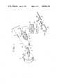
- FIG. 1is a diagram showing a ball shooting device of a pinball game machine incorporating a transducer according to the present invention.
- FIG. 2is a circuit diagram showing one example of the signal processing circuit of FIG. 1;
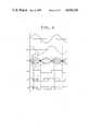
- FIG. 3is a graph showing signal waveforms in the signal processing circuit of FIG. 2.
- a pinball machineincludes, as is well known in the art, a playing field (not shown) covered with transparent glass (not shown).
- a playing field(not shown) covered with transparent glass (not shown).
- an operating handle 1is pivotally mounted on a panel (not shown) positioned beneath the transparent glass.
- the operating handle 1is provided with a finger grip 1a by which handle 1 is rotated in the direction of the arrow in order to shoot a ball.
- an L-shape bar 2is mounted on the inner side of the operating handle 1.
- a bush 14 fixed to the panelrotatably mounts the L-shape bar 2 whereby the operating handle 1 rotates the L-shape bar 2.
- Two flexible wires 3 and 4are coupled to the distal end 2a of the L-shape bar 2.
- the wire 3is fixedly connected at its one end to a fixed base 15 through a tension spring 5 which urges the L-shape bar 2 to abut a fixed pin 16 at a neutral position.
- the other flexible wire 4is deflected about a fixed guide 7 and is coupled at its one end to the distal end 2a of bar 2 and at its other end to one end of a movable bar 8 made of a material that does not affect the fields generated, that is, a material with a dielectric constant of approximately one.
- the other end of the movable bar 8is coupled to another tension spring 6 which is secured to the fixed base 15 and resists movement of bar 8 as the operating handle 1 is turned in the direction of the arrow.
- a coil 9is wound about and is movable with the movable bar 9, the movable coil 8 being supplied as a driving current with an a.c. signal from a signal processing circuit 20.
- a magnetic field generated by the movable coil 9fixed coils 11 and 12 are provided which are in series and wound oppositely relative to each other and spaced apart a predetermined distance.
- the fixed coils 11 and 12are wound on and about a hollow cylindrical tube 10 of a material having the same properties as that of the movable bar 8, which tube 10 is disposed concentrically with the movable bar 8.
- the fixed coils 11 and 12are fixed on the tube 10 for example with tape, an adhesive or the like.
- the hollow cylindrical tube 10is fixedly mounted on the game machine body.
- An a.c. current induced in the fixed coils 11 and 12is converted into a d.c. voltage by the signal processing circuit 20.
- the d.c. voltageis input to a drive circuit 30 and in turn drives the plunger 40a of a solenoid 40.
- the drive circuit 30is comprised by a pulse generator and an amplifier for amplifying a pulse from the pulse generator.
- the drive circuit 30supplies to the solenoid 40 a driven pulse having an amplitude varying in accordance with the input d.c. voltage.
- the solenoid 40advances the plunger 40a when the solenoid coil (not shown) is energized. On the end of the plunger 40a, a spring 41 for absorbing impact and damping sound is mounted.
- the plunger 40aadvances to strike a ball 60 disposed at a shooting position. Under the impact of spring 41, the ball 60 is guided along a guide rail 50 and onto the playing field (not shown). The plunger 40a is returned to the original position as shown in FIG. 1 by a built-in spring or the like after the ball 60 is shot.
- an a.c. signal from a sine wave generator 21is supplied through a drive amplifier to one end of the movable coil 9 wound about the movable bar 8, the other end being grounded.
- One end of the fixed coil 11 wound about the hollow cylindrical tube 10is connected to one end of the fixed coil 12 wound in the opposite direction to that of the fixed coil 12, the other end of the fixed coil 11 being grounded.
- the other end of the fixed coil 12is connected to a negative input terminal of a comparator 24.
- the positive input terminal of the comparator 24is input with a signal obtained by delaying an output from the amplifier 22 by ⁇ /2 in phase in a delay circuit 23.
- the output signal from the amplifier 22is input to the positive input terminal of a comparator 25 of which the negative input terminal is grounded.
- the output terminals of both comparators 24 and 25are connected to both input terminals of an exclusive OR gate 26.
- the output signal from the gate 26is converted into a d.c. signal in a smoothing circuit 27, and the d.c. signal is input to the plunger drive circuit 30 described above.
- the L-shaped bar 2abuts the fixed pin 16, and the movable coil 9 and fixed coil 12 are axially aligned with each other.
- the signal from the sine wave generator 21is amplified by the amplifier 22 and the obtained sine wave signal L1 is supplied to the movable coil 9 and to the comparator 25.
- the comparator 25outputs a rectangular wave signal L4 as shown in FIG. 4.
- the sine wave signal L1is delayed by ⁇ /2 in phase in the delay circuit 23, and in turn the delayed signal L2 is input to the positive terminal of the comparator 24.
- the waveform of an induced signal L3 on the fixed coil 12becomes the same waveform A as that of the sine wave signal L1. Therefore, a rectangular wave signal L6 shown by a solid line is output from the gate 26.
- the wire 4slides about guide 7 and tensions the spring 6 thereby to move the movable bar 8 to the left within the hollow cylindrical tube 10.
- the movable coil 9 together with the movable bar 8are moved to the left to approach axially the fixed coil 11. Since the fixed coils are wound oppositely to each other, the currents induced in the respective fixed coils 11 and 12 tend to cancel each other. As a result, when the movable coil 9 is positioned intermediate the fixed coils 11 and 12, the signal L3 becomes zero. If the movable coil 9 moves beyond the intermediate position and approaches more closely the fixed coil 11, then a waveform D opposite in phase to the waveform A is obtained.
- the signal L3has a waveform A when the movable coil 9 is in registry with the fixed coil 12; a waveform B when the movable coil 9 moves toward the fixed coil 11; and in succession a waveform C and finally a waveform D when the movable coil 9 is in registry with the fixed coil 11.
- the comparator 24compares the signal L2 with the signal L3 to output a signal L5.
- the signal L5has a phase corresponding to the position of the movable coil 9, the phase being shifted as shown by arrows to the right as the movable coil 9 approaches the fixed coil 11.
- the gate 26detects the correspondence between the signals L4 and L5, and in turn outputs a signal L6 having a different pulse width in accordance with the phase shift of the signal L5. That is, as the movable coil approaches the fixed coil 11, the duty ratio of the signal L6 becomes larger.
- the signal L6is input to and smoothed in the smoothing circuit 27, and is converted into a d.c. current.
- the smoothing circuit 27produces a higher d.c. voltage as the duty ratio becomes larger.
- the amount of manipulation of the operating handle 1is converted into a d.c. voltage by means of the movable coil 9, fixed coils 11 and 12, and signal processing circuit 20.
- This d.c. voltageis applied to the known drive circuit 30 to drive the solenoid plunger 40. Therefore, the solenoid plunger 40a strikes the ball 60 with an impact corresponding to the amount of angular movement of the operating handle 1 and at predetermined intervals.
- the actual operation of the operating handle 1is such that a small angular movement causes the power source for the circuits to turn on and a further movement causes the movable bar 8 to start moving.
- a movable coilhas been used as a coil 9, however, the coil 9 may be fixed and the coils 11 and 12 may be moved, by making the hollow cylindrical tube 10 movable instead of the coil 9.
Landscapes
- Physics & Mathematics (AREA)
- General Physics & Mathematics (AREA)
- Engineering & Computer Science (AREA)
- Multimedia (AREA)
- Pinball Game Machines (AREA)
Abstract
Description
Claims (6)
Applications Claiming Priority (2)
| Application Number | Priority Date | Filing Date | Title |
|---|---|---|---|
| JP59-41832[U] | 1984-03-26 | ||
| JP1984041832UJPS60155570U (en) | 1984-03-26 | 1984-03-26 | Movement amount detection device |
Publications (1)
| Publication Number | Publication Date |
|---|---|
| US4634126Atrue US4634126A (en) | 1987-01-06 |
Family
ID=12619234
Family Applications (1)
| Application Number | Title | Priority Date | Filing Date |
|---|---|---|---|
| US06/716,192Expired - LifetimeUS4634126A (en) | 1984-03-26 | 1985-03-26 | Device for converting the amount of a mechanical displacement into electrical signal |
Country Status (4)
| Country | Link |
|---|---|
| US (1) | US4634126A (en) |
| EP (1) | EP0161760A1 (en) |
| JP (1) | JPS60155570U (en) |
| AU (1) | AU550387B2 (en) |
Cited By (30)
| Publication number | Priority date | Publication date | Assignee | Title |
|---|---|---|---|---|
| US4964462A (en)* | 1989-08-09 | 1990-10-23 | Smith Michael L | Tubing collar position sensing apparatus, and associated methods, for use with a snubbing unit |
| US5014781A (en)* | 1989-08-09 | 1991-05-14 | Smith Michael L | Tubing collar position sensing apparatus, and associated methods, for use with a snubbing unit |
| US5322282A (en)* | 1993-07-07 | 1994-06-21 | Data East Pinball, Inc. | Variable response ball receiving device |
| US5434504A (en)* | 1993-10-01 | 1995-07-18 | International Business Machines Corporation | Position sensors for linear motors including plural symmetrical fluxes generated by a planar drive coil and received by planar sense coils being colinear along an axis of motion |
| WO1996024277A1 (en)* | 1995-02-08 | 1996-08-15 | Fraser William A | Checkout counter order divider including merchandise to be purchased |
| US5655770A (en)* | 1995-09-15 | 1997-08-12 | Capcom Coin-Op, Inc. | Pinball solenoid power control system |
| US5657987A (en)* | 1995-09-15 | 1997-08-19 | Capcom Coin-Op, Inc. | Pinball solenoid power control system |
| US6060798A (en)* | 1998-10-30 | 2000-05-09 | Souris; Nicholas | Straight motion |
| US6424696B1 (en)* | 2000-11-10 | 2002-07-23 | Scimed Life Systems, Inc. | X-ray catheter using a step-up transformer |
| US20030032479A1 (en)* | 2001-08-09 | 2003-02-13 | Igt | Virtual cameras and 3-D gaming enviroments in a gaming machine |
| US6540655B1 (en) | 2000-11-10 | 2003-04-01 | Scimed Life Systems, Inc. | Miniature x-ray unit |
| US20030147501A1 (en)* | 2000-11-10 | 2003-08-07 | Geitz Kurt Alfred Edward | Heat sink for miniature x-ray unit |
| US20030149331A1 (en)* | 2000-11-10 | 2003-08-07 | Geitz Kurt Alfred Edward | Miniature X-ray catheter with retractable needles or suction means for positioning at a desired site |
| US6706014B2 (en) | 2000-11-10 | 2004-03-16 | Scimed Life Systems, Inc. | Miniature x-ray unit |
| WO2004002591A3 (en)* | 2002-06-27 | 2004-03-25 | Igt Reno Nev | Trajectory-based 3-d games of chance for video gaming machines |
| US20040075428A1 (en)* | 2000-11-30 | 2004-04-22 | Asylum Research Corporation, A Delaware Corporation | Linear variable differential transformers for high precision position measurements |
| US20040102245A1 (en)* | 2001-08-09 | 2004-05-27 | Igt | 3-D text in a gaming machine |
| US20040102244A1 (en)* | 2001-08-09 | 2004-05-27 | Igt | 3-D reels and 3-D wheels in a gaming machine |
| US6752752B2 (en) | 2000-11-10 | 2004-06-22 | Scimed Life Systems, Inc. | Multi-source x-ray catheter |
| USRE38540E1 (en)* | 1998-01-10 | 2004-06-29 | Bateman Kyle E | Movable target system in which power is inductively transformed to a target carrier |
| US20050075167A1 (en)* | 2001-08-09 | 2005-04-07 | Igt | Game interaction in 3-D gaming environments |
| US20050247134A1 (en)* | 2001-10-30 | 2005-11-10 | Nihon University | Displacement sensor |
| US20060287058A1 (en)* | 2001-08-09 | 2006-12-21 | Igt | Methods and devices for displaying multiple game elements |
| US20080188303A1 (en)* | 2001-08-09 | 2008-08-07 | Igt | Transparent objects on a gaming machine |
| GB2471458A (en)* | 2009-06-29 | 2011-01-05 | Qatar University | An angle to PWM converter for a resolver, using a single high frequency reference sine wave |
| US8384710B2 (en) | 2007-06-07 | 2013-02-26 | Igt | Displaying and using 3D graphics on multiple displays provided for gaming environments |
| US20130088243A1 (en)* | 2011-10-05 | 2013-04-11 | David Scott Nyce | Position sensing head with redundancy |
| US8478560B2 (en) | 2011-01-19 | 2013-07-02 | Honeywell International Inc. | Three wire transformer position sensor, signal processing circuitry, and temperature compensation circuitry therefor |
| US20150102878A1 (en)* | 2013-10-10 | 2015-04-16 | Hyundai Heavy Industries Co., Ltd. | High speed solenoid |
| US9518814B2 (en) | 2008-10-14 | 2016-12-13 | Oxford Instruments Asylum Research Inc | Integrated micro actuator and LVDT for high precision position measurements |
Families Citing this family (2)
| Publication number | Priority date | Publication date | Assignee | Title |
|---|---|---|---|---|
| US6251154B1 (en) | 1992-05-06 | 2001-06-26 | 3M Innovative Properties Company | Dust bag and method of production |
| JPH08226826A (en)* | 1995-02-22 | 1996-09-03 | Mikuni Corp | Magnetic position sensor |
Citations (9)
| Publication number | Priority date | Publication date | Assignee | Title |
|---|---|---|---|---|
| US2881408A (en)* | 1955-02-04 | 1959-04-07 | Minneapolishoneywell Regulator | Inductive coupling for sonar apparatus |
| US3827291A (en)* | 1970-12-01 | 1974-08-06 | Int Research & Dev Co Ltd | Transducer systems for detection of relative displacement |
| US4065715A (en)* | 1975-12-18 | 1977-12-27 | General Motors Corporation | Pulse duration modulated signal transducer |
| US4189674A (en)* | 1978-07-17 | 1980-02-19 | Trw Inc. | Signal transducing means using a bistable magnetic device |
| US4284961A (en)* | 1979-09-19 | 1981-08-18 | The United States Of America As Represented By The Secretary Of The Air Force | Digital position transducer including variable tuning element oscillator |
| US4295651A (en)* | 1978-08-28 | 1981-10-20 | Tomy Kogyo Co., Inc. | Pinball actuator and feed mechanism |
| US4322727A (en)* | 1979-10-03 | 1982-03-30 | Robert Bosch Gmbh | Inductive transducer responsive to displacement along a path |
| US4339739A (en)* | 1979-11-05 | 1982-07-13 | Societe Nationale D'etude Et De Construction De Moteurs D'aviation, "S.N.E.C.M.A." | Linear displacement transducer |
| US4390796A (en)* | 1981-04-15 | 1983-06-28 | Leeds & Northrup Co. | Voltage to duty cycle converter |
Family Cites Families (3)
| Publication number | Priority date | Publication date | Assignee | Title |
|---|---|---|---|---|
| DE1773793C3 (en)* | 1968-07-08 | 1974-02-21 | Karl Dipl.-Ing. 8060 Dachau Kueppers | Circuit arrangement for an electromechanical measuring transducer |
| FR2050626A7 (en)* | 1969-06-18 | 1971-04-02 | Faroux Claude | |
| JPS5819026A (en)* | 1981-07-24 | 1983-02-03 | Nec Corp | Pulse width modulation circuit |
- 1984
- 1984-03-26JPJP1984041832Upatent/JPS60155570U/enactiveGranted
- 1985
- 1985-03-25EPEP85302049Apatent/EP0161760A1/ennot_activeCeased
- 1985-03-26USUS06/716,192patent/US4634126A/ennot_activeExpired - Lifetime
- 1985-03-26AUAU40361/85Apatent/AU550387B2/ennot_activeExpired
Patent Citations (9)
| Publication number | Priority date | Publication date | Assignee | Title |
|---|---|---|---|---|
| US2881408A (en)* | 1955-02-04 | 1959-04-07 | Minneapolishoneywell Regulator | Inductive coupling for sonar apparatus |
| US3827291A (en)* | 1970-12-01 | 1974-08-06 | Int Research & Dev Co Ltd | Transducer systems for detection of relative displacement |
| US4065715A (en)* | 1975-12-18 | 1977-12-27 | General Motors Corporation | Pulse duration modulated signal transducer |
| US4189674A (en)* | 1978-07-17 | 1980-02-19 | Trw Inc. | Signal transducing means using a bistable magnetic device |
| US4295651A (en)* | 1978-08-28 | 1981-10-20 | Tomy Kogyo Co., Inc. | Pinball actuator and feed mechanism |
| US4284961A (en)* | 1979-09-19 | 1981-08-18 | The United States Of America As Represented By The Secretary Of The Air Force | Digital position transducer including variable tuning element oscillator |
| US4322727A (en)* | 1979-10-03 | 1982-03-30 | Robert Bosch Gmbh | Inductive transducer responsive to displacement along a path |
| US4339739A (en)* | 1979-11-05 | 1982-07-13 | Societe Nationale D'etude Et De Construction De Moteurs D'aviation, "S.N.E.C.M.A." | Linear displacement transducer |
| US4390796A (en)* | 1981-04-15 | 1983-06-28 | Leeds & Northrup Co. | Voltage to duty cycle converter |
Non-Patent Citations (2)
| Title |
|---|
| "Twenty-Eighth IEEE Vehicular Technology Conference", Denver, CO, Mar. 22-24, 1978, A Multifunction Integrated Circuit for Automotive Sensors, pp. 533-536. |
| Twenty Eighth IEEE Vehicular Technology Conference , Denver, CO, Mar. 22 24, 1978, A Multifunction Integrated Circuit for Automotive Sensors, pp. 533 536.* |
Cited By (80)
| Publication number | Priority date | Publication date | Assignee | Title |
|---|---|---|---|---|
| US5014781A (en)* | 1989-08-09 | 1991-05-14 | Smith Michael L | Tubing collar position sensing apparatus, and associated methods, for use with a snubbing unit |
| US4964462A (en)* | 1989-08-09 | 1990-10-23 | Smith Michael L | Tubing collar position sensing apparatus, and associated methods, for use with a snubbing unit |
| US5322282A (en)* | 1993-07-07 | 1994-06-21 | Data East Pinball, Inc. | Variable response ball receiving device |
| US5434504A (en)* | 1993-10-01 | 1995-07-18 | International Business Machines Corporation | Position sensors for linear motors including plural symmetrical fluxes generated by a planar drive coil and received by planar sense coils being colinear along an axis of motion |
| WO1996024277A1 (en)* | 1995-02-08 | 1996-08-15 | Fraser William A | Checkout counter order divider including merchandise to be purchased |
| US5655770A (en)* | 1995-09-15 | 1997-08-12 | Capcom Coin-Op, Inc. | Pinball solenoid power control system |
| US5657987A (en)* | 1995-09-15 | 1997-08-19 | Capcom Coin-Op, Inc. | Pinball solenoid power control system |
| USRE38540E1 (en)* | 1998-01-10 | 2004-06-29 | Bateman Kyle E | Movable target system in which power is inductively transformed to a target carrier |
| US6060798A (en)* | 1998-10-30 | 2000-05-09 | Souris; Nicholas | Straight motion |
| WO2000052810A1 (en)* | 1999-03-03 | 2000-09-08 | Nicholas Souris | Coil for an electromagnetic device producing straight motion |
| US7901345B2 (en) | 2000-11-10 | 2011-03-08 | Boston Scientific Scimed, Inc | Miniature X-ray unit |
| US6540655B1 (en) | 2000-11-10 | 2003-04-01 | Scimed Life Systems, Inc. | Miniature x-ray unit |
| US20030147501A1 (en)* | 2000-11-10 | 2003-08-07 | Geitz Kurt Alfred Edward | Heat sink for miniature x-ray unit |
| US20030149331A1 (en)* | 2000-11-10 | 2003-08-07 | Geitz Kurt Alfred Edward | Miniature X-ray catheter with retractable needles or suction means for positioning at a desired site |
| US6706014B2 (en) | 2000-11-10 | 2004-03-16 | Scimed Life Systems, Inc. | Miniature x-ray unit |
| US20100266101A1 (en)* | 2000-11-10 | 2010-10-21 | Boston Scientific Scimed, Inc. | Miniature x-ray unit |
| US7031432B2 (en) | 2000-11-10 | 2006-04-18 | Scimed Life Systems, Inc. | Miniature x-ray catheter with retractable needles or suction means for positioning at a desired site |
| US6999559B2 (en) | 2000-11-10 | 2006-02-14 | Scimed Life Systems, Inc. | Heat sink for miniature x-ray unit |
| US6424696B1 (en)* | 2000-11-10 | 2002-07-23 | Scimed Life Systems, Inc. | X-ray catheter using a step-up transformer |
| US6752752B2 (en) | 2000-11-10 | 2004-06-22 | Scimed Life Systems, Inc. | Multi-source x-ray catheter |
| US20040075428A1 (en)* | 2000-11-30 | 2004-04-22 | Asylum Research Corporation, A Delaware Corporation | Linear variable differential transformers for high precision position measurements |
| US7372254B2 (en) | 2000-11-30 | 2008-05-13 | Asylum Research Corporation | Linear force detecting element formed without ferromagnetic materials which produces a resolution in a range of microns or less |
| US7271582B2 (en) | 2000-11-30 | 2007-09-18 | Asylum Research Corporation | Linear variable differential transformers for high precision position measurements |
| US20070200559A1 (en)* | 2000-11-30 | 2007-08-30 | Asylum Research Corporation | Position Sensing Assembly with Synchronizing Capability |
| US7262592B2 (en) | 2000-11-30 | 2007-08-28 | Asylum Research Corporation | Linear variable differential transformers for high precision position measurements |
| US7233140B2 (en) | 2000-11-30 | 2007-06-19 | Asylum Research Corporation | Position sensing assembly with sychronizing capability |
| US7459904B2 (en) | 2000-11-30 | 2008-12-02 | Roger Proksch | Precision position sensor using a nonmagnetic coil form |
| US20060202683A1 (en)* | 2000-11-30 | 2006-09-14 | Roger Proksch | Linear variable differential transformers for high precision position measurements |
| US7038443B2 (en) | 2000-11-30 | 2006-05-02 | Asylum Research Corporation | Linear variable differential transformers for high precision position measurements |
| US20060186876A1 (en)* | 2000-11-30 | 2006-08-24 | Roger Proksch | Linear variable differential transformers for high precision position measurements |
| US20060186877A1 (en)* | 2000-11-30 | 2006-08-24 | Roger Proksch | Linear variable differential transformers for high precision position measurements |
| US20060186878A1 (en)* | 2000-11-30 | 2006-08-24 | Roger Proksch | Linear variable differential transformers for high precision position measurements |
| US20060192551A1 (en)* | 2000-11-30 | 2006-08-31 | Roger Proksch | Linear variable differential transformers for high precision position measurements |
| US7367885B2 (en) | 2001-08-09 | 2008-05-06 | Igt | 3-D text in a gaming machine |
| US8523672B2 (en)* | 2001-08-09 | 2013-09-03 | Igt | 3-D reels and 3-D wheels in a gaming machine |
| US9418504B2 (en) | 2001-08-09 | 2016-08-16 | Igt | 3-D reels and 3-D wheels in a gaming machine |
| US20050233799A1 (en)* | 2001-08-09 | 2005-10-20 | Igt | Virtual cameras and 3-D gaming environments in a gaming machine |
| US6887157B2 (en) | 2001-08-09 | 2005-05-03 | Igt | Virtual cameras and 3-D gaming environments in a gaming machine |
| US20050075167A1 (en)* | 2001-08-09 | 2005-04-07 | Igt | Game interaction in 3-D gaming environments |
| US9135774B2 (en) | 2001-08-09 | 2015-09-15 | Igt | 3-D reels and 3-D wheels in a gaming machine |
| US20080045331A1 (en)* | 2001-08-09 | 2008-02-21 | Igt | Virtual cameras and 3-d gaming enviroments in a gaming machine |
| US20060287058A1 (en)* | 2001-08-09 | 2006-12-21 | Igt | Methods and devices for displaying multiple game elements |
| US20040102244A1 (en)* | 2001-08-09 | 2004-05-27 | Igt | 3-D reels and 3-D wheels in a gaming machine |
| US20080188303A1 (en)* | 2001-08-09 | 2008-08-07 | Igt | Transparent objects on a gaming machine |
| US20080188304A1 (en)* | 2001-08-09 | 2008-08-07 | Igt | 3-d text in a gaming machine |
| US20040102245A1 (en)* | 2001-08-09 | 2004-05-27 | Igt | 3-D text in a gaming machine |
| US7465230B2 (en) | 2001-08-09 | 2008-12-16 | Igt | Virtual cameras and 3-D gaming environments in a gaming machine |
| US7572186B2 (en)* | 2001-08-09 | 2009-08-11 | Igt | Virtual cameras and 3-D gaming environments in a gaming machine |
| US20120289306A1 (en)* | 2001-08-09 | 2012-11-15 | Igt | 3-d reels and 3-d wheels in a gaming machine |
| US8267767B2 (en) | 2001-08-09 | 2012-09-18 | Igt | 3-D reels and 3-D wheels in a gaming machine |
| US20030032479A1 (en)* | 2001-08-09 | 2003-02-13 | Igt | Virtual cameras and 3-D gaming enviroments in a gaming machine |
| US7901289B2 (en) | 2001-08-09 | 2011-03-08 | Igt | Transparent objects on a gaming machine |
| US7909696B2 (en) | 2001-08-09 | 2011-03-22 | Igt | Game interaction in 3-D gaming environments |
| US8012019B2 (en) | 2001-08-09 | 2011-09-06 | Igt | 3-D text in a gaming machine |
| US7934994B2 (en) | 2001-08-09 | 2011-05-03 | Igt | Virtual cameras and 3-D gaming environments in a gaming machine |
| US8002623B2 (en) | 2001-08-09 | 2011-08-23 | Igt | Methods and devices for displaying multiple game elements |
| US7281432B2 (en)* | 2001-10-30 | 2007-10-16 | Nihon University | Displacement sensor with an excitation coil and a detection coil |
| US20050247134A1 (en)* | 2001-10-30 | 2005-11-10 | Nihon University | Displacement sensor |
| US9358453B2 (en) | 2002-06-27 | 2016-06-07 | Igt | Trajectory-based 3-D games of chance for video gaming machines |
| US7918730B2 (en) | 2002-06-27 | 2011-04-05 | Igt | Trajectory-based 3-D games of chance for video gaming machines |
| US20110165930A1 (en)* | 2002-06-27 | 2011-07-07 | Igt | Trajectory-based 3-d games of chance for video gaming machines |
| WO2004002591A3 (en)* | 2002-06-27 | 2004-03-25 | Igt Reno Nev | Trajectory-based 3-d games of chance for video gaming machines |
| US20110165929A1 (en)* | 2002-06-27 | 2011-07-07 | Igt | Trajectory-based 3-d games of chance for video gaming machines |
| US20110165931A1 (en)* | 2002-06-27 | 2011-07-07 | Igt | Trajectory-based 3-d games of chance for video gaming machines |
| US8550893B2 (en) | 2002-06-27 | 2013-10-08 | Igt | Trajectory-based 3-D games of chance for video gaming machines |
| US8500535B2 (en) | 2002-06-27 | 2013-08-06 | Igt | Trajectory-based 3-D games of chance for video gaming machines |
| US8523671B2 (en) | 2002-06-27 | 2013-09-03 | Igt | Trajectory-based 3-D games of chance for video gaming machines |
| US8992320B2 (en) | 2002-06-27 | 2015-03-31 | Igt | Trajectory-based 3-D games of chance for video gaming machines |
| US9072967B2 (en) | 2002-06-27 | 2015-07-07 | Igt | Trajectory-based 3-D games of chance for video gaming machines |
| US9613496B2 (en) | 2002-06-27 | 2017-04-04 | Igt | Trajectory-based 3-D games of chance for video gaming machines |
| GB2405107A (en)* | 2002-06-27 | 2005-02-23 | Igt Reno Nev | Trajectory-based 3-D games of chance for video gaming machines |
| US8384710B2 (en) | 2007-06-07 | 2013-02-26 | Igt | Displaying and using 3D graphics on multiple displays provided for gaming environments |
| US10337890B2 (en) | 2008-10-14 | 2019-07-02 | Oxford Instruments Afm Inc | Integrated micro actuator and LVDT for high precision position measurements |
| US9518814B2 (en) | 2008-10-14 | 2016-12-13 | Oxford Instruments Asylum Research Inc | Integrated micro actuator and LVDT for high precision position measurements |
| GB2471458A (en)* | 2009-06-29 | 2011-01-05 | Qatar University | An angle to PWM converter for a resolver, using a single high frequency reference sine wave |
| US8478560B2 (en) | 2011-01-19 | 2013-07-02 | Honeywell International Inc. | Three wire transformer position sensor, signal processing circuitry, and temperature compensation circuitry therefor |
| US8692541B2 (en)* | 2011-10-05 | 2014-04-08 | David Scott Nyce | Position sensing head with redundancy |
| US20130088243A1 (en)* | 2011-10-05 | 2013-04-11 | David Scott Nyce | Position sensing head with redundancy |
| US9472330B2 (en)* | 2013-10-10 | 2016-10-18 | Hyundai Heavy Industries Co., Ltd. | High speed solenoid |
| US20150102878A1 (en)* | 2013-10-10 | 2015-04-16 | Hyundai Heavy Industries Co., Ltd. | High speed solenoid |
Also Published As
| Publication number | Publication date |
|---|---|
| AU550387B2 (en) | 1986-03-20 |
| JPH0319903Y2 (en) | 1991-04-26 |
| JPS60155570U (en) | 1985-10-16 |
| EP0161760A1 (en) | 1985-11-21 |
| AU4036185A (en) | 1985-10-03 |
Similar Documents
| Publication | Publication Date | Title |
|---|---|---|
| US4634126A (en) | Device for converting the amount of a mechanical displacement into electrical signal | |
| US6480752B1 (en) | Final operating element positioning device | |
| US4375289A (en) | Apparatus for monitoring a boundary line | |
| US5065660A (en) | Piano tuning system | |
| US4100480A (en) | Position and velocity sensors | |
| DE2736450A1 (en) | DEVICE FOR DAMPING TURNTABLE ROTATION | |
| GB2060940A (en) | Device for measuring the speed of a movable system with respect to a data carrier | |
| US4792707A (en) | Disk tracking device | |
| US5982354A (en) | Manual input unit | |
| EP0916953B1 (en) | Pulse signal generator | |
| US6670804B1 (en) | Method for determining the angular position of a rotative part which performs a rotational movement | |
| US4538930A (en) | Adaptive print hammer damper | |
| DD150111A1 (en) | DEVICE FOR WAY-POWER COORDINATION AT ANTASTSYSTEMEN | |
| JP3966995B2 (en) | Game ball launcher for bullet ball machines | |
| US5045784A (en) | Tachometer noise reduction system using a pickup coil to cancel the noise from the tachometer signal | |
| JP2000123686A (en) | Shift position sensing device | |
| CA1100051A (en) | Record player | |
| JPH0319904Y2 (en) | ||
| JPH09121589A (en) | Linear motor | |
| EP0394268B1 (en) | Motorised faders | |
| JP4154878B2 (en) | Position detecting device and positioning device | |
| JPH07333092A (en) | Amplification rate variable device and inner pressure detection device, electromagnetic induction type displacement detector, and tire air pressure sensor of traveling body | |
| US3159706A (en) | Apparatus for producing phase shift in electronic organs | |
| US5877598A (en) | Horizontal linearity control | |
| JPS6125503Y2 (en) |
Legal Events
| Date | Code | Title | Description |
|---|---|---|---|
| AS | Assignment | Owner name:KABUSHIKI KAISHA UNIVERSAL, 561, OAZA ARAI, OYAMA- Free format text:ASSIGNMENT OF ASSIGNORS INTEREST.;ASSIGNOR:KIMURA, YUTAKA;REEL/FRAME:004409/0481 Effective date:19850402 | |
| STCF | Information on status: patent grant | Free format text:PATENTED CASE | |
| FEPP | Fee payment procedure | Free format text:PAYOR NUMBER ASSIGNED (ORIGINAL EVENT CODE: ASPN); ENTITY STATUS OF PATENT OWNER: LARGE ENTITY Free format text:PAT HLDR NO LONGER CLAIMS SMALL ENT STAT AS SMALL BUSINESS (ORIGINAL EVENT CODE: LSM2); ENTITY STATUS OF PATENT OWNER: LARGE ENTITY | |
| FPAY | Fee payment | Year of fee payment:4 | |
| FPAY | Fee payment | Year of fee payment:8 | |
| FPAY | Fee payment | Year of fee payment:12 | |
| AS | Assignment | Owner name:ARUZE CORPORATION, JAPAN Free format text:ASSIGNMENT OF ASSIGNORS INTEREST;ASSIGNOR:KABUSHIKI KAISHA UNIVERSAL;REEL/FRAME:010216/0164 Effective date:19990730 Owner name:ARUZE CORPORATION, JAPAN Free format text:ASSIGNMENT OF ASSIGNORS INTEREST;ASSIGNOR:KABUSHIKI KAISHA UNIVERSAL;REEL/FRAME:010247/0735 Effective date:19990730 |