US4634019A - Container with plastic hinge - Google Patents
Container with plastic hingeDownload PDFInfo
- Publication number
- US4634019A US4634019AUS06/840,409US84040986AUS4634019AUS 4634019 AUS4634019 AUS 4634019AUS 84040986 AUS84040986 AUS 84040986AUS 4634019 AUS4634019 AUS 4634019A
- Authority
- US
- United States
- Prior art keywords
- hinge
- lip portion
- cover
- section
- skirt
- Prior art date
- Legal status (The legal status is an assumption and is not a legal conclusion. Google has not performed a legal analysis and makes no representation as to the accuracy of the status listed.)
- Expired - Lifetime
Links
- 239000004033plasticSubstances0.000titleclaimsabstractdescription13
- 239000002184metalSubstances0.000claimsabstractdescription17
- 238000001125extrusionMethods0.000claimsabstractdescription9
- 239000011324beadSubstances0.000claimsdescription30
- 230000002093peripheral effectEffects0.000claimsdescription5
- 229920003266Leaf®Polymers0.000description4
- 238000010276constructionMethods0.000description1
- 229920005669high impact polystyrenePolymers0.000description1
- 239000004797high-impact polystyreneSubstances0.000description1
- 238000002347injectionMethods0.000description1
- 239000007924injectionSubstances0.000description1
- 238000004519manufacturing processMethods0.000description1
- 238000000034methodMethods0.000description1
- 238000000926separation methodMethods0.000description1
Images
Classifications
- B—PERFORMING OPERATIONS; TRANSPORTING
- B65—CONVEYING; PACKING; STORING; HANDLING THIN OR FILAMENTARY MATERIAL
- B65D—CONTAINERS FOR STORAGE OR TRANSPORT OF ARTICLES OR MATERIALS, e.g. BAGS, BARRELS, BOTTLES, BOXES, CANS, CARTONS, CRATES, DRUMS, JARS, TANKS, HOPPERS, FORWARDING CONTAINERS; ACCESSORIES, CLOSURES, OR FITTINGS THEREFOR; PACKAGING ELEMENTS; PACKAGES
- B65D43/00—Lids or covers for rigid or semi-rigid containers
- B65D43/14—Non-removable lids or covers
- B65D43/16—Non-removable lids or covers hinged for upward or downward movement
- B65D43/163—Non-removable lids or covers hinged for upward or downward movement the container and the lid being made separately
Definitions
- the inventionrelates to a container having a body for holding a product and having a cover for closing the body. More particularly, the invention relates to a container of the type in which the body is formed with an upper lip portion defining an opening of predetermined size and shape.
- the coveris shaped as an inverted dish and includes a skirt depending from the periphery of a top wall having the same general size and shape as the opening in the body. When the cover is in a closed position, the top wall closes the opening of the body while the skirt telescopes downwardly over the lip portion of the body.
- the inventionis especially concerned with a container of the foregoing type in which a plastic hinge connects the cover to a body to swing between open and closed positions.
- a plastic hingeconnects the cover to a body to swing between open and closed positions.
- the plastic hingeis injection molded and comprises a pair of swingably connected mounting leafs adapted to be joined to the lip portion of a metal body and to the skirt of the cover.
- To secure the mounting leaf to the metal bodyit is necessary to form holes in the lip portion of the body, to insert lugs on the mounting leaf into the holes and then to upset the ends of the lugs.
- a similar assembly techniqueis used for the mounting leaf of the cover when the cover also is made of metal.
- the general aim of the present inventionis to provide a container having a new and improved plastic hinge which is simpler to manufacture than prior hinges of the same general type and which may be assembled with the body and the cover in a quicker and easier manner.
- a more detailed object of the inventionis to achieve the foregoing by providing a plastic hinge which is formed as a single-piece extrusion and which is adapted to be attached to both the body and the cover with a simple snap fit.
- the inventionalso resides in the unique shape of the hinge and in the novel construction of the lip portion of the body and the skirt of the cover to enable assembly of the hinge by a simple snap-on operation, to enable the hinge to fit compactly between the cover and the body and to enable free swinging of the cover between open and closed positions.
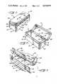
- FIG. 1is a rear fragmentary perspective view of one embodiment of a container equipped with a new and improved hinge incorporating the unique features of the present invention, the cover of the container being shown in a closed position.
- FIG. 2is a front fragmentary perspective view of the container, the cover being shown in an open position.
- FIG. 3is a fragmentary perspective view showing the hinge assembled with the cover and being assembled to the container body.
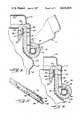
- FIG. 4is an enlarged fragmentary cross-section taken substantially along the line 4--4 of FIG. 1.
- FIG. 5is a fragmentary perspective view of the hinge.
- FIG. 6is a view similar to FIG. 4 but shows a slightly modified container equipped with the hinge of the invention.
- the inventionis embodied in a container 10 having a cover 11 swingable between a closed position (FIG. 1) and an open position (FIG. 2) in which a box-like body 12 of rectangular cross-section is completely exposed.
- the bodyis made of sheet metal and includes two end walls 13 and 14 and two somewhat longer front and rear walls 15 and 16. At the corner between the end wall 13 and the rear wall 16, the ends of the sheet metal are locked together by a conventional seam (not visible).
- a bottom member(not shown) which also preferably is made of metal is secured to the lower end of the body 12.
- the extreme upper end of the bodythus is rounded and is free of sharp edges while the lower end of the hem 20 defines a downwardly facing edge 21 (FIG. 4) within the body.
- a peripheral bead 22which is formed by deforming the metal of the body outwardly.
- the beadis located some distance below the lower edge 21 of the hem 20.
- the cover 11also is preferably made of sheet metal and includes a substantially flat top wall 23 having generally the same rectangular size and shape as the interior of the body 12. Formed integrally with and depending from the periphery of the top wall 23 is a skirt 25 whose lower end is curled outwardly, upwardly and then inwardly so as to define an outwardly protruding peripheral bead 26 (FIGS. 3 and 4) of generally circular cross-section at the lower end of the skirt.
- the skirt 25telescopes downwardly over the lip portion 18 of the body with the lower side of the bead 26 being located adjacent the upper side of the bead 22.
- the skirt 25resiliently embraces the lip portion to hold the cover snugly but releasably in its closed position.
- the cover 11is mounted to swing between open and closed positions on the body 12 by a single-piece hinge 30 extruded from plastic and adapted to be assembled with both the cover and the body with a snap fit.
- the hingemay be manufactured in a relatively simple manner and at relatively high speeds and may be easily made in different lengths for containers of different sizes. Assembly of the hinge to the cover and the body is simplified significantly by virtue of the fact that the hinge may be simply snapped in place and, as an incident thereto, holds the cover in hinged relation with the body.
- the present hinge 30is made of high impact polystyrene and is formed by profile-extruding the plastic and then cutting the elongated extrusion into separate pieces each having a length equal to the required length of the hinge.
- the hingeis horizontally elongated in the direction of elongation of the lip portion 18 and, as shown in FIG. 4, is generally S-shaped in transverse cross-section.
- the hingeincludes upper and lower hook sections 32 and 34 formed integrally with and located at the upper and lower ends, respectively, of an upright intermediate section 36.
- the intermediate section 36 of the hinge 30is flat and planar and is disposed in flat face-to-face relation with the outer surface of the lip portion 18 of the rear wall 16 of the body 12.
- the height of the intermediate sectionis approximately equal to the distance between the upper side of the bead 22 and the rounded upper end of the hem 20.
- the upper hook section 32curves inwardly and then downwardly from the upper end of the intermediate section 36 and includes a flat and upright lower end portion 38 whose outer side lies substantially face-to-face with the inner side of the hem 20 of the rear wall 16.
- the outer side of the extreme lower end of the upper hook sectionis defined by a surface 40 which slopes upwardly and outwardly and whose upper terminus defines an upwardly facing shoulder 42.
- the flat upright portion 38 of the upper hook section 32is disposed in closely spaced relation with the intermediate section 36, the spacing being somewhat less than the thickness of the hem 20.
- the upper hook section 32is simply telescoped downwardly onto the hem 20 and, as an incident thereto, the inclined surface 40 engages the rounded upper end of the hem and cams the flat upright portion 38 outwardly against the resiliency of the plastic.
- the flat upright portion 38springs inwardly to cause the shoulder to snap beneath the edge.
- the flat upright portion 38 and the opposing intermediate section 36resiliently grip the hem 20 to hold the hinge 30 on the body 12, and, in addition, the raw edge 21 of the hem bites into the shoulder 42 to restrict upward separation of the hinge from the body.
- the intermediate section 36 of the hinge 30is received within an inwardly offset recess 46 (FIGS. 2, 3 and 4) formed in the exterior of the lip portion 18 along the rear wall 16 of the body 12.
- the recessis formed by using coacting deforming dies (not shown) to inwardly offset an intermediate section of the lip portion from the adjacent end sections of the lip portion.
- the intermediate section 36lies in flat face-to-face relation with the recessed section 46 of the lip portion 18 and has a thickness equal to or slightly less than the depth of the recess.
- the intermediate section 36 of the hinge 30lies substantially flush with the outer sides of the end sections of the rear lip portion 18 and does not interfere with the skirt 25 of the cover 11 when the cover is in its closed position.
- the length of the recess 46is just very slightly greater than the length of the intermediate section 36 of the hinge and thus the ends of the intermediate section are engageable with the ends of the recess to restrict the hinge 30 against sliding lengthwise along the lip portion 18.
- the lower hook section 34 of the hinge 30first curves outwardly and upwardly from and then inwardly toward the lower end portion of the intermediate section 36 so as to define a curl having a circular cross-section and having an inner diameter somewhat greater than the outer diameter of the bead 26 of the skirt 25 (see FIG. 4).
- the free end 48 of the curl 34is inclined upwardly and outwardly and is spaced outwardly from the outer side of the intermediate section 36 by a distance somewhat less than the outer diameter of the bead 26.
- Assembly of the cover 11 and the hinge 30is effected by moving the cover downwardly relative to the hinge to cause the bead 26 to snap into the lower curl 34.
- the bead 26cams against the free end 48 of the curl 34 to force that end away from the intermediate section 36 and permit the bead to enter the curl.
- the lattersprings back to its original condition so as to captivate the bead vertically in the curl.
- the bead 26 and the curl 34are both formed with a circular cross-section, the bead is capable of pivoting within the curl to permit swinging of the cover 11.
- interference between the skirt 25 and the curl 34 during such swingingis prevented by forming an elongated and generally rectangular slot 50 (FIGS. 3 and 4) through the skirt just above the bead 26.
- the slot 50is alined with and is spaced inwardly from the free end 48 of the curl 34.
- the coveris swung to its open position shown in phantom lines in FIG.
- the edges of the slot 50move around the curl 34 to permit the skirt 25 to clear the curl and thereby prevent interference between the skirt and the curl.
- the slot 50may be formed either by simply blanking out and completely removing a rectangular section of metal from the skirt (see FIG. 4) or by leaving the blanked out metal connected to the lower edge of the slot and curling such metal around the bead 26 as indicated at 52 in FIG. 6. In the latter case, the bead 26 is reinforced and stiffened by the curled metal 52 and is less likely to flex or deform when snapped into the curl 34 of the hinge 30 during assembly.
- the preferred manner of assemblyis to snap the bead 26 of the cover 11 into the curl 34 of the hinge 30 and then to snap the hinge with the attached cover onto the hem 20 of the body 12 (see FIG. 3).
- the hinge 30may first be snapped onto the body 12 and then the bead 26 of the cover 11 may be snapped into the curl 34.
- the present inventionbrings to the art a new and extremely simple plastic hinge which is especially useful for swingably connecting a metal cover 11 to a metal container body 12. Assembly of the components of the container 10 may be achieved quickly and easily since both the body and the cover are adapted to be attached to the hinge with a simple snap fit. Because the hinge initially is part of a continuous extrusion, hinges for containers of various sizes may be formed with the same extrusion dies, the extrusion then simply being cut into lengths appropriate for the different containers.
- the hinge axis defined by the bead 26 and the curl 34may be located closely adjacent the rear wall 16 of the body 12 so as to enable the skirt 25 of the cover 11 to telescope over the lip portion with a snug fit when the cover is swung to its closed position.
Landscapes
- Engineering & Computer Science (AREA)
- Mechanical Engineering (AREA)
- Closures For Containers (AREA)
Abstract
Description
Claims (8)
Priority Applications (1)
| Application Number | Priority Date | Filing Date | Title |
|---|---|---|---|
| US06/840,409US4634019A (en) | 1986-03-14 | 1986-03-14 | Container with plastic hinge |
Applications Claiming Priority (1)
| Application Number | Priority Date | Filing Date | Title |
|---|---|---|---|
| US06/840,409US4634019A (en) | 1986-03-14 | 1986-03-14 | Container with plastic hinge |
Publications (1)
| Publication Number | Publication Date |
|---|---|
| US4634019Atrue US4634019A (en) | 1987-01-06 |
Family
ID=25282309
Family Applications (1)
| Application Number | Title | Priority Date | Filing Date |
|---|---|---|---|
| US06/840,409Expired - LifetimeUS4634019A (en) | 1986-03-14 | 1986-03-14 | Container with plastic hinge |
Country Status (1)
| Country | Link |
|---|---|
| US (1) | US4634019A (en) |
Cited By (31)
| Publication number | Priority date | Publication date | Assignee | Title |
|---|---|---|---|---|
| US4789078A (en)* | 1987-10-19 | 1988-12-06 | Mobil Oil Corporation | Wastebasket with lid catch |
| WO1989002401A1 (en)* | 1987-09-16 | 1989-03-23 | Harmony Foods, Inc. | Food container with a hinged cover |
| US4951869A (en)* | 1988-08-05 | 1990-08-28 | Mathew Szapucki | Coin telephone collection box |
| US20040173481A1 (en)* | 2003-11-06 | 2004-09-09 | Encore Holdings Limited | Media storage disk box |
| US20040218884A1 (en)* | 2001-07-20 | 2004-11-04 | Adc Telecommunications, Inc. | Cable trough cover |
| US6877260B1 (en)* | 1999-07-31 | 2005-04-12 | Rowenta-Werke Gmbh | Iron skirt |
| US20050098340A1 (en)* | 2003-11-05 | 2005-05-12 | Adc Telecommunications, Inc. | Cover for cable trough |
| US20050167302A1 (en)* | 2003-09-08 | 2005-08-04 | Jan Bjerregaard | Metal packaging |
| US20050173596A1 (en)* | 2004-02-10 | 2005-08-11 | Herzog Daniel M. | Hinge for cable trough cover |
| US20050178803A1 (en)* | 2003-01-02 | 2005-08-18 | Six Continents Hotels, Inc. | Container for dispensing comestibles |
| US7124909B1 (en)* | 2003-01-09 | 2006-10-24 | V V G I Corporation | Hinged lid container |
| US20060243845A1 (en)* | 2005-02-21 | 2006-11-02 | Harald Wegner | Wire-winding device for earphones, especially hands free kits for mobile phones |
| US20070001561A1 (en)* | 2004-01-06 | 2007-01-04 | Irving Sabo | Hinge assembly |
| USD554502S1 (en) | 2006-08-10 | 2007-11-06 | J.L. Clark, Inc. | Container having sliding door |
| US20090010782A1 (en)* | 2005-03-22 | 2009-01-08 | Miele & Cie. Kg | Fan Unit, Particularly for a Vacuum Cleaner |
| US20090032651A1 (en)* | 2007-08-01 | 2009-02-05 | Derek Sayres | Hinge for Cable Trough Cover |
| US20090032280A1 (en)* | 2007-08-01 | 2009-02-05 | Owens Ryan J | Hinge for Cable Trough Cover |
| US20090101645A1 (en)* | 2007-10-18 | 2009-04-23 | Mccormick & Company, Incorporated | Tamper resistant container with locking rim |
| USD599203S1 (en) | 2008-03-03 | 2009-09-01 | Mccormick & Company, Incorporated | Tamper evident lid for container with a locking lid and rim |
| US20100096346A1 (en)* | 2008-10-17 | 2010-04-22 | Douglas Heim Enterprises, Inc. | Display shelf for bowling ball |
| US20100270323A1 (en)* | 2007-08-03 | 2010-10-28 | George Zeiler | Hinged lid for a food container |
| US20100308052A1 (en)* | 2007-08-03 | 2010-12-09 | George Zeiler | Hinged lid with retaining feature |
| US20120067914A1 (en)* | 2010-09-22 | 2012-03-22 | Itt Manufacturing Enterprises, Inc. | Self centering hinge design for concentric sealing of an enclosure |
| US20120199513A1 (en)* | 2011-02-04 | 2012-08-09 | Wagner Charles E | Storage Container |
| US9305598B2 (en) | 2013-04-08 | 2016-04-05 | Disc Graphics Inc. | Package and container assembly and method of manufacturing same |
| USD845139S1 (en) | 2016-09-19 | 2019-04-09 | Mccormick & Company, Incorporated | Spice container |
| USD846398S1 (en) | 2016-09-19 | 2019-04-23 | Mccormick & Company, Incorporated | Container with three door lid |
| USD850912S1 (en) | 2016-09-19 | 2019-06-11 | Mccormick & Company, Incorporated | Three door container lid |
| US10441101B2 (en) | 2016-09-19 | 2019-10-15 | Mccormick & Company, Incorporated | Three door lid and container utilizing the same |
| WO2021128541A1 (en)* | 2019-12-26 | 2021-07-01 | 辉捷制造有限公司 | Push/pull-type lunch box |
| US20230029189A1 (en)* | 2021-07-22 | 2023-01-26 | Jose Munoz | Rod Holder |
Citations (4)
| Publication number | Priority date | Publication date | Assignee | Title |
|---|---|---|---|---|
| US3592354A (en)* | 1969-11-03 | 1971-07-13 | Elmer T Nielsen | Hinge construction for two-piece containers |
| US4089467A (en)* | 1977-08-08 | 1978-05-16 | Curtiscorp, Inc. | Polystyrene container with polypropylene hinge and latch |
| US4154362A (en)* | 1978-05-12 | 1979-05-15 | Curtiscorp, Inc. | Self-attaching hinge for polystyrene containers and latch means integral therewith |
| US4471881A (en)* | 1983-06-28 | 1984-09-18 | J. L. Clark Manufacturing Co. | Container with metal body and plastic hinge |
- 1986
- 1986-03-14USUS06/840,409patent/US4634019A/ennot_activeExpired - Lifetime
Patent Citations (4)
| Publication number | Priority date | Publication date | Assignee | Title |
|---|---|---|---|---|
| US3592354A (en)* | 1969-11-03 | 1971-07-13 | Elmer T Nielsen | Hinge construction for two-piece containers |
| US4089467A (en)* | 1977-08-08 | 1978-05-16 | Curtiscorp, Inc. | Polystyrene container with polypropylene hinge and latch |
| US4154362A (en)* | 1978-05-12 | 1979-05-15 | Curtiscorp, Inc. | Self-attaching hinge for polystyrene containers and latch means integral therewith |
| US4471881A (en)* | 1983-06-28 | 1984-09-18 | J. L. Clark Manufacturing Co. | Container with metal body and plastic hinge |
Cited By (61)
| Publication number | Priority date | Publication date | Assignee | Title |
|---|---|---|---|---|
| WO1989002401A1 (en)* | 1987-09-16 | 1989-03-23 | Harmony Foods, Inc. | Food container with a hinged cover |
| US4789078A (en)* | 1987-10-19 | 1988-12-06 | Mobil Oil Corporation | Wastebasket with lid catch |
| US4951869A (en)* | 1988-08-05 | 1990-08-28 | Mathew Szapucki | Coin telephone collection box |
| US6877260B1 (en)* | 1999-07-31 | 2005-04-12 | Rowenta-Werke Gmbh | Iron skirt |
| US7469090B2 (en) | 2001-07-20 | 2008-12-23 | Adc Telecommunications, Inc. | Cable trough cover |
| US20040218884A1 (en)* | 2001-07-20 | 2004-11-04 | Adc Telecommunications, Inc. | Cable trough cover |
| US20070248309A1 (en)* | 2001-07-20 | 2007-10-25 | Adc Telecommunications, Inc. | Cable trough cover |
| US7113685B2 (en) | 2001-07-20 | 2006-09-26 | Adc Telecommunications, Inc. | Cable trough cover |
| US6934456B2 (en)* | 2001-07-20 | 2005-08-23 | Adc Telecommunications, Inc. | Cable trough cover |
| US20060285812A1 (en)* | 2001-07-20 | 2006-12-21 | Adc Telecommunications, Inc. | Cable trough cover |
| US7224880B2 (en) | 2001-07-20 | 2007-05-29 | Adc Telecommunications, Inc. | Cable trough cover |
| US20050178803A1 (en)* | 2003-01-02 | 2005-08-18 | Six Continents Hotels, Inc. | Container for dispensing comestibles |
| US7124909B1 (en)* | 2003-01-09 | 2006-10-24 | V V G I Corporation | Hinged lid container |
| US7350642B2 (en)* | 2003-09-08 | 2008-04-01 | Glud & Marstrand A/S | Metal packaging |
| US7051872B2 (en)* | 2003-09-08 | 2006-05-30 | Glud & Marstrand A/S | Metal packaging |
| US7232032B2 (en) | 2003-09-08 | 2007-06-19 | Glud & Marstrand A/S | Metal packaging |
| US20060021899A1 (en)* | 2003-09-08 | 2006-02-02 | Glud & Marstrand A/S | Metal packaging |
| US20050279657A1 (en)* | 2003-09-08 | 2005-12-22 | Glud & Marstrand A/S | Metal packaging |
| US20050167302A1 (en)* | 2003-09-08 | 2005-08-04 | Jan Bjerregaard | Metal packaging |
| US7411126B2 (en) | 2003-11-05 | 2008-08-12 | Adc Telecommunications, Inc. | Cover for cable trough |
| US20060191700A1 (en)* | 2003-11-05 | 2006-08-31 | Adc Telecommunications, Inc. | Cover for Cable Trough |
| US7060901B2 (en) | 2003-11-05 | 2006-06-13 | Adc Telecommunications, Inc. | Cover for cable trough |
| US20050098340A1 (en)* | 2003-11-05 | 2005-05-12 | Adc Telecommunications, Inc. | Cover for cable trough |
| US20040173481A1 (en)* | 2003-11-06 | 2004-09-09 | Encore Holdings Limited | Media storage disk box |
| US20070001561A1 (en)* | 2004-01-06 | 2007-01-04 | Irving Sabo | Hinge assembly |
| US20060191701A1 (en)* | 2004-02-10 | 2006-08-31 | Adc Telecommunications, Inc. | Hinge for Cable Trough Cover |
| US7041897B2 (en) | 2004-02-10 | 2006-05-09 | Adc Telecommunications, Inc. | Hinge for cable trough cover |
| US7326863B2 (en) | 2004-02-10 | 2008-02-05 | Adc Telecommunications, Inc. | Hinge for cable trough cover |
| US20050173596A1 (en)* | 2004-02-10 | 2005-08-11 | Herzog Daniel M. | Hinge for cable trough cover |
| US20060243845A1 (en)* | 2005-02-21 | 2006-11-02 | Harald Wegner | Wire-winding device for earphones, especially hands free kits for mobile phones |
| US20090010782A1 (en)* | 2005-03-22 | 2009-01-08 | Miele & Cie. Kg | Fan Unit, Particularly for a Vacuum Cleaner |
| USD554502S1 (en) | 2006-08-10 | 2007-11-06 | J.L. Clark, Inc. | Container having sliding door |
| US20090032651A1 (en)* | 2007-08-01 | 2009-02-05 | Derek Sayres | Hinge for Cable Trough Cover |
| US20090032280A1 (en)* | 2007-08-01 | 2009-02-05 | Owens Ryan J | Hinge for Cable Trough Cover |
| US8330042B2 (en) | 2007-08-01 | 2012-12-11 | Adc Telecommunications, Inc. | Hinge for cable trough cover |
| US7612300B2 (en) | 2007-08-01 | 2009-11-03 | Adc Telecommunications, Inc. | Hinge for cable trough cover |
| US7615710B2 (en) | 2007-08-01 | 2009-11-10 | Adc Telecommunications, Inc. | Hinge for cable trough cover |
| US8261935B2 (en)* | 2007-08-03 | 2012-09-11 | Huhtamaki, Inc. | Hinged lid with retaining feature |
| US7963421B2 (en)* | 2007-08-03 | 2011-06-21 | Huhtamaki, Inc. | Hinged lid for a food container |
| US20100270323A1 (en)* | 2007-08-03 | 2010-10-28 | George Zeiler | Hinged lid for a food container |
| US20100276438A1 (en)* | 2007-08-03 | 2010-11-04 | George Zeiler | Hinged lid for a food container |
| US20100308052A1 (en)* | 2007-08-03 | 2010-12-09 | George Zeiler | Hinged lid with retaining feature |
| US20090101645A1 (en)* | 2007-10-18 | 2009-04-23 | Mccormick & Company, Incorporated | Tamper resistant container with locking rim |
| US8286817B2 (en) | 2007-10-18 | 2012-10-16 | Mccormick & Company, Incorporated | Tamper resistant container with locking rim |
| USD615862S1 (en) | 2008-03-03 | 2010-05-18 | Mccormick & Company, Incorporated | Tamper evident lid for a container |
| USD604161S1 (en) | 2008-03-03 | 2009-11-17 | Mccormick & Company, Incorporated | Tamper evident lid for a container |
| USD599203S1 (en) | 2008-03-03 | 2009-09-01 | Mccormick & Company, Incorporated | Tamper evident lid for container with a locking lid and rim |
| US20100096346A1 (en)* | 2008-10-17 | 2010-04-22 | Douglas Heim Enterprises, Inc. | Display shelf for bowling ball |
| US20120067914A1 (en)* | 2010-09-22 | 2012-03-22 | Itt Manufacturing Enterprises, Inc. | Self centering hinge design for concentric sealing of an enclosure |
| US20120199513A1 (en)* | 2011-02-04 | 2012-08-09 | Wagner Charles E | Storage Container |
| US9114909B2 (en)* | 2011-02-04 | 2015-08-25 | Western Industries, Inc. | Storage container |
| US9305598B2 (en) | 2013-04-08 | 2016-04-05 | Disc Graphics Inc. | Package and container assembly and method of manufacturing same |
| US9666230B2 (en) | 2013-04-08 | 2017-05-30 | Disc Graphics Inc. | Package and container assembly and method of manufacturing same |
| USD845139S1 (en) | 2016-09-19 | 2019-04-09 | Mccormick & Company, Incorporated | Spice container |
| USD846398S1 (en) | 2016-09-19 | 2019-04-23 | Mccormick & Company, Incorporated | Container with three door lid |
| USD850912S1 (en) | 2016-09-19 | 2019-06-11 | Mccormick & Company, Incorporated | Three door container lid |
| US10441101B2 (en) | 2016-09-19 | 2019-10-15 | Mccormick & Company, Incorporated | Three door lid and container utilizing the same |
| USD925354S1 (en) | 2016-09-19 | 2021-07-20 | Mccormick & Company, Incorporated | Spice container |
| WO2021128541A1 (en)* | 2019-12-26 | 2021-07-01 | 辉捷制造有限公司 | Push/pull-type lunch box |
| US20230029189A1 (en)* | 2021-07-22 | 2023-01-26 | Jose Munoz | Rod Holder |
| US12310346B2 (en)* | 2021-07-22 | 2025-05-27 | Jose Munoz | Rod holder |
Similar Documents
| Publication | Publication Date | Title |
|---|---|---|
| US4634019A (en) | Container with plastic hinge | |
| US4471881A (en) | Container with metal body and plastic hinge | |
| CA1226826A (en) | Hinged plastic container | |
| CA1122132A (en) | Children's lunch box | |
| US6478184B2 (en) | Two piece hinged closure | |
| EP1027254B1 (en) | Metal container having resilient hinged connector | |
| JP2532090Y2 (en) | Caps and containers with lids that flip elastically | |
| JPS6276147U (en) | ||
| US3984028A (en) | Container hinge construction | |
| JPS589527Y2 (en) | compact container | |
| JPS5846724Y2 (en) | compact container | |
| JP3636793B2 (en) | One-touch hinge cap | |
| JPH0327971Y2 (en) | ||
| JPS5846725Y2 (en) | compact container | |
| US3717278A (en) | Hinged box | |
| JPS6138496Y2 (en) | ||
| JPH0233712Y2 (en) | ||
| JPS5922857Y2 (en) | Assembled accessories - containers | |
| JPS6021082Y2 (en) | air freshener container | |
| JPS6120967Y2 (en) | ||
| JPH0531088Y2 (en) | ||
| JPS6214966Y2 (en) | ||
| JPH1057259A (en) | Lidded container made of synthetic resin | |
| JPS6013796Y2 (en) | Container hinge device | |
| JPH0323136Y2 (en) |
Legal Events
| Date | Code | Title | Description |
|---|---|---|---|
| AS | Assignment | Owner name:J. L. CLARK MANUFACTURING CO., 2300 SIXTH STREET, Free format text:ASSIGNMENT OF ASSIGNORS INTEREST.;ASSIGNOR:PHERIGO, DOUGLAS E.;REEL/FRAME:004579/0076 Effective date:19860313 | |
| STCF | Information on status: patent grant | Free format text:PATENTED CASE | |
| AS | Assignment | Owner name:CLARCOR INC., A CORP. OF DE Free format text:MERGER;ASSIGNORS:CJL CORPORATION, A CORP. OF DE (MERGED INTO);J.L. CLARK MANUFACTURING CO., A CORP. OF DE (CHANGED TO);REEL/FRAME:005206/0156 Effective date:19870913 | |
| AS | Assignment | Owner name:J.L. CLARK INC., 2300 SIXTH STREET, P.O. BOX 7000, Free format text:ASSIGNMENT OF ASSIGNORS INTEREST.;ASSIGNOR:CLARCOR INC.;REEL/FRAME:005148/0469 Effective date:19890911 | |
| FEPP | Fee payment procedure | Free format text:PAYOR NUMBER ASSIGNED (ORIGINAL EVENT CODE: ASPN); ENTITY STATUS OF PATENT OWNER: LARGE ENTITY | |
| FPAY | Fee payment | Year of fee payment:4 | |
| FPAY | Fee payment | Year of fee payment:8 | |
| FPAY | Fee payment | Year of fee payment:12 |