US4633543A - Hand vacuum cleaner - Google Patents
Hand vacuum cleanerDownload PDFInfo
- Publication number
- US4633543A US4633543AUS06/670,553US67055384AUS4633543AUS 4633543 AUS4633543 AUS 4633543AUS 67055384 AUS67055384 AUS 67055384AUS 4633543 AUS4633543 AUS 4633543A
- Authority
- US
- United States
- Prior art keywords
- motor
- housing
- fan
- cooling air
- air
- Prior art date
- Legal status (The legal status is an assumption and is not a legal conclusion. Google has not performed a legal analysis and makes no representation as to the accuracy of the status listed.)
- Expired - Lifetime
Links
Images


Classifications
- A—HUMAN NECESSITIES
- A47—FURNITURE; DOMESTIC ARTICLES OR APPLIANCES; COFFEE MILLS; SPICE MILLS; SUCTION CLEANERS IN GENERAL
- A47L—DOMESTIC WASHING OR CLEANING; SUCTION CLEANERS IN GENERAL
- A47L9/00—Details or accessories of suction cleaners, e.g. mechanical means for controlling the suction or for effecting pulsating action; Storing devices specially adapted to suction cleaners or parts thereof; Carrying-vehicles specially adapted for suction cleaners
- A47L9/22—Mountings for motor fan assemblies
- A—HUMAN NECESSITIES
- A47—FURNITURE; DOMESTIC ARTICLES OR APPLIANCES; COFFEE MILLS; SPICE MILLS; SUCTION CLEANERS IN GENERAL
- A47L—DOMESTIC WASHING OR CLEANING; SUCTION CLEANERS IN GENERAL
- A47L5/00—Structural features of suction cleaners
- A47L5/12—Structural features of suction cleaners with power-driven air-pumps or air-compressors, e.g. driven by motor vehicle engine vacuum
- A47L5/22—Structural features of suction cleaners with power-driven air-pumps or air-compressors, e.g. driven by motor vehicle engine vacuum with rotary fans
- A47L5/24—Hand-supported suction cleaners
- A47L5/26—Hand-supported suction cleaners with driven dust-loosening tools
Definitions
- This inventionpertains to the art of vacuum cleaner devices and more particularly to a hand vacuum cleaner.
- the inventionis particularly applicable as a device for suction cleaning items and places where conventional larger sized vacuums are inconvenient and, more particularly, where a hand held vacuum with a revolving brush that provides a vibrating and sweeping action is particularly advantageous.
- a principal problem with these prior art devicesis that in order to obtain powerful suction with a revolving brush the hand vacuums have been relatively heavy since they have typically been constructed of a metal casing to support a powerful suction motor and absorb the vibrations of a revolving brush.
- a metal casinghas been necessary to withstand the forces of impinging articles against the casing walls which have been propelled against the walls by the cleaner during operation.
- Mere lightweight plastic materialshave been unable to withstand the forces of such impinging articles over a period of time without risk of damage to the casing itself, or, at worst, propelling an item out from a broken casing towards an operator of the cleaner.
- Another common problem with hand held vacuum cleanersis the provision of a convenient yet effective means for sealing a dirt and soil collecting bag to the cleaner housing. It is important that the bag may be easily separable from the cleaner for emptying, but it is also important that a dust tight seal be made upon reattachment of the bag to the cleaner and that such dust tight seal must be capable of being maintained over a large number of operations of removal and reattachment of the bag.
- Most conventional type hand vacuum cleanerswhich merely use an elastomeric gasket in combination with a mechanical camming device to seal the bag to the vacuum housing have been unsuccessful over a period of time due to deformation of the gasket and mechanical relaxation of the camming parts. As dust leaks from such a hand vacuum during operation, it is particularly noticeable to an operator and, accordingly, a most unattractive and undesirable type of cleaner failure.
- the present inventioncontemplates a new and improved hand vacuum cleaner which overcomes all the above referred to problems and others to provide a new hand vacuum which is simple in design, economical to manufacture, compact and lightweight, but provides powerful suction action with a revolving brush, readily adaptable to a plurality of uses in a variety of cleaning situations, easy to assemble, easy to operate, easy to detach, empty and reattach the cleaner bag and which provides improved hand vacuum cleaner operation.
- a hand held vacuum cleanerhaving a housing, rotating brush, and selectively separable bag assembly.
- the housingincludes a bag attachment collar having a recessed slot area for reception of an elastomeric retaining ring having a sealing and retaining bead of the bag assembly.
- the bag assemblyis positively sealed during operation to the housing to substantially preclude passing of dust particles.
- the housingfurther contains a motor and fan for drawing in air from a housing nozzle.
- the fanis mounted to the motor at a motor shaft locking surface including a wall portion tapering towards the fan.
- the shaft locking surfaceis in locking cooperation with a mating fan bore locking surface including a wall portion tapered for close reception of the motor shaft locking surface.
- a motor shaft extension and belt for driving the revolving brushis provided.
- the shaft extensionis threadedly mounted to the motor shaft and the belt is received on the shaft extension.
- the fanis received on the motor shaft intermediate of the motor and the shaft extension in engagement to the shaft extension whereby a torque applied by resistance of the belt and brush to shaft rotation continually tightens the shaft extension to the motor shaft and fixes the fan to the motor shaft.
- the housingfurther includes a stone shield circumferentially spaced about the fan whereby the stone shield blocks items impinging against the housing from the fan from damaging the housing.
- the stone shieldincludes a side wall having an upper portion tapered away from the front wall to preclude perpendicular impingement of the items against the side wall.
- the housingincludes a nozzle assembly having a nozzle with integrally formed opposite first and second bearing housing cavities, the cavities being sized to closely receive first and second bearing housings of the revolving brush.
- a nozzle guardincludes first and second bearing housing retaining elements disposed for deflecting interference fit to the bearing housings whereby the brush is positively retained in a nozzle assembly to minimize vibrational movement and conduct heat from the housing.
- the housingincludes a motor mount shell portion including a baffle wall extending from a housing outer wall to contiguous engagement to the motor.
- the housing outer wallincludes a plurality of air inlet slots and air outlet slots oppositely spaced about the baffle wall whereby motor cooling air is kept separated from vacuum working air and is drawn in the air inlet slots and expelled from the air outlet slots.
- the housingincludes an air deflector substantially received in the bag assembly having a terminal end portion disposed tapering radially inwardly past the vacuum working air channel from the housing outer wall and bag outer wall whereby the deflector directs the working air to facilitate greater storage of vacuum dirt in the bag and prevents heavy objects received in the bag from rolling back into the housing and contacting the fan.
- the housingpreferably comprises first and second half shells, fixedly engaged, and includes mating tongue in groove sealing about the half shells' perimeters whereby the sealing seals the motor from contamination by dust particles carried by the working air.
- One benefit obtained by use of the present inventionis a hand vacuum which is compact and lightweight but provides powerful suction with a revolving brush and improved hand vacuum operation.
- Another benefit obtained from the present inventionis a hand vacuum which provides an improved seal of the bag assembly to the housing.
- a further benefit of the present inventionis a hand vacuum with a revolving brush having a motor shaft locking surface for locking cooperation with the motor fan in which operation of the brush provides a continuous torque to tighten the fan to the motor shaft.
- Yet another benefit of the present inventionis a hand vacuum housing including a stone shield to block potentially damaging items from impinging against the housing side walls, a motor mount shell which segregates motor cooling air from vacuum working air, and further includes an air deflector received in the bag assembly to facilitate greater storage of vacuumed dirt and block heavy objects received in the bag from rolling back into the housing and contacting the fan.
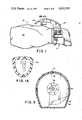
- FIG. 1is a side elevational view of a hand vacuum formed in accordance with the present invention
- FIG. 1Ais a cross-sectional view taken along line 1A--1A of FIG. 1 particularly illustrating assembly aid wire grooves in the vacuum handle;
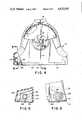
- FIG. 2is an enlarged cross-sectional view of the hand vacuum housing
- FIG. 2Ais an enlarged sectional view of FIG. 2 particularly illustrating the tongue in groove assembly of the housing;
- FIG. 2Bis a cross-sectional view taken along line 2B--2B of FIG. 2A;
- FIG. 2Cis an enlarged sectional view of FIG. 2 particularly showing the elastomeric retaining ring of the bag assembly as it is received on the hand vacuum housing;
- FIG. 2Dis an enlarged sectional view of FIG. 2 taken along lines 2D--2D particularly showing an air vent slot construction
- FIG. 3is a cross-sectional view taken along line 3--3 of FIG. 2;
- FIG. 4is an enlarged front elevational view with partial cutaways in section of the present invention.
- FIG. 5is a cross-sectional view taken along line 5--5 of FIG. 4;
- FIG. 6is a cross-sectional view taken along line 6--6 of FIG. 4;
- FIG. 7is an enlarged elevational view in partial section of the motor and fan assembly.
- FIGURESshow a hand vacuum device comprised of a housing 10 and selectively separable bag assembly 12.
- the vacuum housing 10includes a motor mount portion 16, a fan chamber 18, a nozzle 20 and a handle 22.
- An annular bag attachment collar 26is provided for attachment of the bag assembly 12 to the housing 10.
- the collar 26includes a recessed slot area 30 extending circumferentially about the housing 10.
- the bag assembly 12includes an elastomeric retaining ring 32 having a sealing and retaining bead 34 (FIG. 2C) for reception in the recessed slot area 30 whereby the bag assembly 12 is positively sealed during cleaner operation to substantially preclude passing of dust particles out of the bag past the retaining ring 32.
- the retaining ring 32includes a lead on flange 36 and a bag assembly attachment flange 38, the bead 34 depending radially inwardly from these flanges and being positioned generally intermediate of the flanges.
- a receptacle bag 40 of the bag assembly constructed of a conventionally known cotton twill used for vacuum cleaner bagsis fixed to ring 32 at the bag assembly attachment flange 38 with a high strength thread 42.
- a bottom wall 46 of the sealing and retaining bead 34contacts a projection 48 in the recess slot area 30 and is slightly deformed about the projection by high contact pressure created by the hoop strength of the retaining ring 32.
- the bottom wall 46 engaging the projection 48 in the recess slot area 30produces a high unit pressure where the projection 48 engages bead 34.
- the elastomeric ring 32possesses a hoop strength due to its elastomeric nature and it is sized for a close fit over the collar 26.
- the sealing force of the projection 48 engaging the elastomeric wall 46is greater than the air pressure to leak through the seal and accordingly precludes the leaking of the fine dust particles.
- a second pressure surfaceoccurs at the point designated by numeral 50 in FIG. 2C at the bead vertical wall engaging the opposed recess slot area vertical wall. This pressure is produced by the back pressure in the bag 40 during operation as a result of the forcing of air into the bag 40.
- the third pressure pointoccurs at an area designated by the numeral 52 where the sloping wall of the recessed slot area 30 contacts the front wall 53 of the bead 34 to produce a pressure area which is the result of the natural hoop strength of the elastomeric retaining ring and a preselected interference fit between the ring and the attachment collar.
- a pull tab(not shown) is sewn into the retaining ring 32 to facilitate easy separation of the bag assembly 12 from the housing 10.
- the ring 32is sized relative to the collar 26 such that the ring is stretched 5-7% to move the bead 34 into the recessed slot area 30. Such stretching produces the hoop strength earlier mentioned.
- the seal designhas been optimized to give proper and improved sealing while allowing ease in attachment and removal of the bag assembly.
- the retaining ring 32is not only decorative but is constructed to minimize the material in the part and yet give proper cross-sectional area to produce a quality seal over repeated stretchings.
- the hand vacuum housing 10is preferably constructed of a lightweight plastic.
- most lightweight plastics which are normally satisfactory for such a housing constructionpresent a problem when they are subjected to repeated impingements from the kind of articles which may be sucked in by hand vacuum.
- Such articlescomprise small pebbles, coins, screws, nails, etc., which, upon being drawn into the fan chamber 18 are oftentimes propelled against the chamber side walls by the fan before passing out of the chamber with the working air.
- the present inventionincludes a stone shield 60 to block the potentially damaging effects of such propelled objects.
- the housing 10contains a motor 62 having a motor shaft 64 supported in bearing 65 to which a fan 66 is mounted in fan chamber 18.
- Working air drawn in through nozzle 20 and through fan chamber ingress aperture 68is expelled from the chamber through channel 70.
- the channel 70is spaced from the motor mount portion 16 by the motor mount portion peripheral wall to provide a working air channel unobstructed by cooling air passageways.
- the stone shield 60blocks heavy objects that may be propelled against the housing side walls.
- stone shield 60is constructed of aluminized cold rolled steel.
- the front wallis contiguous to the nozzle 20 and comprises the ingress aperture 68 for the working air.
- the side wall 72includes an upper portion tapered away from the front wall 74 to preclude perpendicular impingement of the items against the side wall over that portion. After impingement against the stone shield, objects are communicated out of the fan chamber 18 through the channel 70.
- the present inventionincludes an improved structure for mounting the fan 66 to the motor 62.
- Projecting out from the motor mount portion 16 of the housing 10 and into the fan chambers 18is the motor shaft 64 supported in bearing 65. This shaft is driven in rotation by the motor.
- the shaft 64includes three portions.
- a first portion or support shoulder 80 having a generally cylindrical configurationis loosely received in a fan first bore chamber 82 defined by fan bore lead-on flange 83 and fan counterbore shoulder 85.
- a tapering fan bore locking surface 84Depending from the support shoulder portion 80 is a tapering fan bore locking surface 84.
- the end portion of the shaft 64comprises a threaded portion 86.
- shaft locking surface 84is closely received against a tapered wall portion 88 of the fan 66 such that the mating tapers of surface 84 and wall portion 88 can cooperate through engagement to lock the fan 66 to the shaft 64 upon sufficient urging of the fan 66 towards the motor 62.
- the mating reception of the shaft taper into the fan bore taperlocks the fan to the motor shaft when the fan is sufficiently pressed onto the motor shaft.
- the revolving brush 96(FIGS. 4 and 6) is rotated by a belt (not shown) received around the brush at an intermediate portion generally immediately below the shaft extension 90.
- the beltis received on the shaft extension at generally its point of lessermost diameter 97 (FIG. 7).
- the beltis constructed of an elastomeric material and is stretched over the distance from the brush 96 to the shaft extension 90 to maintain a gripping action on both the shaft extension 90 and the brush 96.
- a torqueis applied by resistance of the belt and brush to motor shaft rotation to the shaft extension 90 to continually tighten down the shaft extension 90 onto the threaded portion 86.
- Yet another feature of the present inventionis that such a fan mounting structure absorbs impact loads on the fan better.
- the fanhas a greater tendency to give against the load than a threaded mounting structure. This allows the fan to act somewhat as a shock absorber to heavy objects that are drawn into the cleaner.
- the nozzle portion 20 of the present inventionhouses the revolving brush 96.
- the brush 96includes opposed end bearings 98 which support the brush and allow its rotational movement.
- the nozzleincludes integrally formed opposed bearing housing cavities 100 sized to closely receive the bearing housings of the brush.
- a nozzle guard 102is fastened to the nozzle portion 20 with conventional threaded fasteners (not shown) inserted into receiving members 104.
- the nozzle guardhas openings through which brush elements 105 extend and through which vacuumed dirt may pass.
- the guard 102further includes bearing housing retaining elements 106 which impart the force to retain the brush 96 in cavities 100.
- the retaining element 106is sized such that there is an interference fit against the bearing 98 due to deflection of the clip element 106 which holds the brush solid within the nozzle.
- the brush 96is normally unbalanced and will want to vibrate during operation. There is thus a necessity that the brush be positively retained in as close a fit as possible to minimize vibrational movement.
- the nozzle guardis preferably constructed of metallic material as is the bearing assembly 98.
- the retaining element 106thus can operate as a source of heat transfer. Since the bearing 98 is also in contact with the plastic nozzle housing at the cavities 100, heat must be dissipated through the retaining element 106 and out through the sole plate portion of the nozzle guard 102.
- the nozzle guard 102also includes a locating and locking protruding dimple 110 disposed for cooperative association with the nozzle whereby the nozzle and nozzle guard are in cooperative support.
- the housing 10is constructed of opposed first and second half housing elements which mate along a center line 112. To buttress the housing, and in particular the nozzle 20 at the center line, dimple 110 in combination with the nozzle guard front wall 114 support the nozzle at its terminal end portion about the center line 112. Such structure minimizes damage to the cleaner by deflection or separation of the housing half elements at the nozzle terminal end portion.
- the housing 10includes a motor mount portion 16 for receiving the motor 62 that includes a plurality of air vents 120 provided for communicating the ingress and egress of cooling air to the motor 62.
- a baffle wall 122engages the periphery of the motor 62 to define a motor cooling air intake chamber 124 and an exhaust chamber 126.
- the motor 62includes a cooling air fan (not shown) which draws cooling air in through the vents 120 of the intake chamber 124 into air vents (not shown) of the motor, through the body of the motor, out motor vents in the exhaust chamber 126 and ultimately out into the environment through the air vents 120 in the exhaust chamber 126.
- the baffle wall 122precludes cooling air exhausted from the exhaust chamber 126 from intermixing with air in the intake chamber 124 without passing through the motor 62.
- the vents 120 in exhaust chamber 126include a sloped side wall 127 (FIG. 2D) contiguous to the baffle wall 122 and the vents of the intake chamber 124.
- the sloped side wall 127effectively directs the exhaust air towards the rear of the cleaner and away from the vents of the intake chamber 124 to inhibit mixing of exhaust cooling air with intake cooling air.
- the inventionemploys a tongue in groove mating fit along the entire periphery of the cleaner between opposing first and second housing halves and about the periphery of the motor mount portion 16.
- the housing handle 22further includes besides the tongue in groove sealing, several assembly aid wire grooves 130 for communicating switch wires from the cleaner cord 132 to the cleaner on/off switch 134 (FIG. 1).
Landscapes
- Engineering & Computer Science (AREA)
- Mechanical Engineering (AREA)
- Electric Vacuum Cleaner (AREA)
- Nozzles For Electric Vacuum Cleaners (AREA)
- Structures Of Non-Positive Displacement Pumps (AREA)
- Electric Suction Cleaners (AREA)
- Filters For Electric Vacuum Cleaners (AREA)
- Manipulator (AREA)
Abstract
Description
Claims (2)
Priority Applications (36)
| Application Number | Priority Date | Filing Date | Title |
|---|---|---|---|
| US06/670,553US4633543A (en) | 1984-11-09 | 1984-11-09 | Hand vacuum cleaner |
| CA000478963ACA1227004A (en) | 1984-11-09 | 1985-04-12 | Hand vacuum cleaner |
| AU50196/85AAU585285B2 (en) | 1984-11-09 | 1985-11-08 | Hand-held vacuum cleaner |
| GB8614554AGB2181338B (en) | 1984-11-09 | 1985-11-08 | Hand held vacuum cleaner |
| JP60505053AJPH0646975B2 (en) | 1984-11-09 | 1985-11-08 | Portable vacuum cleaner |
| CH519/89ACH672244A5 (en) | 1984-11-09 | 1985-11-08 | Hand vacuum cleaner with nozzle guard |
| CH518/89ACH672243A5 (en) | 1984-11-09 | 1985-11-08 | Hand vacuum cleaner with nozzle guard |
| DE3590577ADE3590577C2 (en) | 1984-11-09 | 1985-11-08 | Hand vacuum cleaner with nozzle guard |
| PCT/US1985/002231WO1986002817A1 (en) | 1984-11-09 | 1985-11-08 | Hand vacuum cleaner |
| KR1019860700420AKR930001453B1 (en) | 1984-11-09 | 1985-11-08 | Hand vacuum cleaner |
| DE3546885ADE3546885C2 (en) | 1984-11-09 | 1985-11-08 | Handheld vacuum cleaner |
| EP85905727AEP0201566B1 (en) | 1984-11-09 | 1985-11-08 | Hand vacuum cleaner |
| DE19853590577DE3590577T1 (en) | 1984-11-09 | 1985-11-08 | |
| NL8520370ANL8520370A (en) | 1984-11-09 | 1985-11-09 | HAND VACUUM CLEANER. |
| US06/878,050US4791699A (en) | 1984-11-09 | 1986-06-24 | Hand vacuum cleaner |
| US06/877,881US4730362A (en) | 1984-11-09 | 1986-06-24 | Hand vacuum cleaner |
| SE8603041ASE461008B (en) | 1984-11-09 | 1986-07-08 | HANDHAALLEN WOMAN CLEANER WITH EASTERLY SOCKET |
| CH2983/86ACH672410A5 (en) | 1984-11-09 | 1986-11-08 | |
| US07/000,451US4741070A (en) | 1984-11-09 | 1987-01-05 | Hand vacuum cleaner |
| CA000541857ACA1291602C (en) | 1984-11-09 | 1987-07-10 | Hand vacuum cleaner |
| CA000541856ACA1274358A (en) | 1984-11-09 | 1987-07-10 | Hand vacuum cleaner |
| CA000541855ACA1288908C (en) | 1984-11-09 | 1987-07-10 | Hand vacuum cleaner |
| US07/078,559US4788740A (en) | 1984-11-09 | 1987-07-28 | Hand vacuum cleaner |
| GB8800354AGB2200040B (en) | 1984-11-09 | 1988-01-08 | Hand held vacuum cleaner |
| US07/153,971US4891861A (en) | 1984-11-09 | 1988-02-09 | Hand vacuum cleaner |
| SE8801189ASE461129B (en) | 1984-11-09 | 1988-03-30 | HANDHAALLEN WOMEN CLEANER WITH NOZZLE UNIT PROVIDED WITH THE LAGERFESTEN |
| SE8801187ASE461126B (en) | 1984-11-09 | 1988-03-30 | HANDHAALLEN DUST CLEANER WITH FLAEKT FASTING DEVICE |
| SE8801188ASE461127B (en) | 1984-11-09 | 1988-03-30 | HANDHAALLEN DUST CLEANER WITH STONE SCREEN FURNISHED HOUSE |
| SE8801190ASE461128B (en) | 1984-11-09 | 1988-03-30 | HANDHAALLEN VACUUM CLEANER WITH SPECIAL VACUUM SHELTER |
| GB8822254AGB2208590B (en) | 1984-11-09 | 1988-09-22 | Hand held vacuum cleaner |
| US07/332,558US4918781A (en) | 1984-11-09 | 1989-03-31 | Hand vacuum cleaner |
| GB8907454AGB2224196B (en) | 1984-11-09 | 1989-04-03 | Hand held vacuum cleaner |
| GB8907453AGB2215590B (en) | 1984-11-09 | 1989-04-03 | Hand held vacuum cleaner |
| AU41384/89AAU611056B2 (en) | 1984-11-09 | 1989-09-14 | Hand vacuum cleaner |
| AU41385/89AAU615573B2 (en) | 1984-11-09 | 1989-09-14 | Hand vacuum cleaner |
| CA000615685ACA1331262C (en) | 1984-11-09 | 1990-03-30 | Hand vacuum cleaner |
Applications Claiming Priority (1)
| Application Number | Priority Date | Filing Date | Title |
|---|---|---|---|
| US06/670,553US4633543A (en) | 1984-11-09 | 1984-11-09 | Hand vacuum cleaner |
Related Child Applications (4)
| Application Number | Title | Priority Date | Filing Date |
|---|---|---|---|
| US06/877,881DivisionUS4730362A (en) | 1984-11-09 | 1986-06-24 | Hand vacuum cleaner |
| US06/878,050DivisionUS4791699A (en) | 1984-11-09 | 1986-06-24 | Hand vacuum cleaner |
| US07/000,451ContinuationUS4741070A (en) | 1984-11-09 | 1987-01-05 | Hand vacuum cleaner |
| US07/078,559DivisionUS4788740A (en) | 1984-11-09 | 1987-07-28 | Hand vacuum cleaner |
Publications (1)
| Publication Number | Publication Date |
|---|---|
| US4633543Atrue US4633543A (en) | 1987-01-06 |
Family
ID=24690859
Family Applications (1)
| Application Number | Title | Priority Date | Filing Date |
|---|---|---|---|
| US06/670,553Expired - LifetimeUS4633543A (en) | 1984-11-09 | 1984-11-09 | Hand vacuum cleaner |
Country Status (12)
| Country | Link |
|---|---|
| US (1) | US4633543A (en) |
| EP (1) | EP0201566B1 (en) |
| JP (1) | JPH0646975B2 (en) |
| KR (1) | KR930001453B1 (en) |
| AU (3) | AU585285B2 (en) |
| CA (1) | CA1227004A (en) |
| CH (1) | CH672410A5 (en) |
| DE (2) | DE3546885C2 (en) |
| GB (4) | GB2181338B (en) |
| NL (1) | NL8520370A (en) |
| SE (5) | SE461008B (en) |
| WO (1) | WO1986002817A1 (en) |
Cited By (18)
| Publication number | Priority date | Publication date | Assignee | Title |
|---|---|---|---|---|
| US4905342A (en)* | 1984-06-11 | 1990-03-06 | Sharp Kabushiki Kaisha | Portable vacuum cleaner |
| US4989294A (en)* | 1989-07-28 | 1991-02-05 | Breuer Electric Mfg. Co. | Floor cleaning tool for vacuum cleaner |
| US5057131A (en)* | 1988-09-26 | 1991-10-15 | The Scott Fetzer Company | Vacuum cleaner filter bag assembly |
| US5129128A (en)* | 1990-01-12 | 1992-07-14 | Trc Acquisition Corporation | Vacuum cleaner |
| US5287592A (en)* | 1993-01-08 | 1994-02-22 | Royal Appliance Mfg. Co. | Electrically insulating belt drive for vacuum cleaner motor assembly |
| US5331716A (en)* | 1993-01-08 | 1994-07-26 | Black & Decker Inc. | Vacuum cleaner with extendable hose and brush disengagement |
| USD352141S (en) | 1993-01-08 | 1994-11-01 | Black & Decker Inc. | Hand-held vacuum cleaner |
| US5388302A (en)* | 1993-01-08 | 1995-02-14 | Black & Decker Inc. | Vacuum cleaner housing and airflow chamber |
| USD358009S (en) | 1993-09-16 | 1995-05-02 | Electrolux Corporation | Handheld vacuum cleaner |
| US5421058A (en)* | 1993-10-01 | 1995-06-06 | Royal Appliance Mfg. Co. | Hand-held vacuum cleaner |
| US5448794A (en)* | 1993-09-16 | 1995-09-12 | Electrolux Corporation | Corded handheld vacuum cleaner |
| USD368992S (en) | 1994-09-27 | 1996-04-16 | Bissell Inc. | Hand-held vacuum cleaner |
| US5974623A (en)* | 1998-02-04 | 1999-11-02 | Rexair, Inc. | Vacuum cleaner motor housing |
| US6497001B2 (en) | 2001-01-12 | 2002-12-24 | Royal Appliance Mfg. Co. | Hand-held vacuum cleaner with a detachable head |
| USD512803S1 (en) | 2004-10-26 | 2005-12-13 | Doris Kendrick | Vacuum cleaner |
| US20060156508A1 (en)* | 2005-01-14 | 2006-07-20 | Royal Appliance Mfg. Co. | Vacuum cleaner with cyclonic separating dirt cup and dirt cup door |
| US20100115726A1 (en)* | 2008-10-22 | 2010-05-13 | Timothy Groff | Handheld vacuum cleaner |
| USD626708S1 (en) | 2008-03-11 | 2010-11-02 | Royal Appliance Mfg. Co. | Hand vacuum |
Families Citing this family (4)
| Publication number | Priority date | Publication date | Assignee | Title |
|---|---|---|---|---|
| US5218736A (en)* | 1990-01-12 | 1993-06-15 | Trc Acquisition Corporation | Vacuum cleaner |
| GB0315181D0 (en)* | 2003-06-28 | 2003-08-06 | Black & Decker Inc | Vacuum cleaner |
| JP2007532154A (en)* | 2004-04-08 | 2007-11-15 | ロイ、グリプスケ、アンド、サンズ、プロプライエタリ、リミテッド | Portable vacuum or blower / vacuum unit |
| AU2005230210B2 (en)* | 2004-04-08 | 2011-01-20 | Roy Gripske & Sons Pty. Ltd | Portable vacuum or blower/vacuum unit |
Citations (21)
| Publication number | Priority date | Publication date | Assignee | Title |
|---|---|---|---|---|
| BE571913A (en)* | 1958-07-10 | |||
| US1861261A (en)* | 1930-01-25 | 1932-05-31 | Electric Vacuum Cleaner Co | Hand vacuum cleaner |
| US1871624A (en)* | 1931-02-20 | 1932-08-16 | Joseph A Loewinsohn | Vacuum cleaner |
| US1878858A (en)* | 1930-05-05 | 1932-09-20 | Hoover Co | Suction cleaner |
| US2184446A (en)* | 1938-03-09 | 1939-12-26 | Hoover Co | Suction cleaner |
| DE694801C (en)* | 1938-12-23 | 1940-08-08 | Festo Maschf Stoll G | Vacuum cleaner for wood grinding machines |
| GB538613A (en)* | 1939-03-06 | 1941-08-11 | Hoover Co | Improvements in or relating to suction cleaners |
| US2309583A (en)* | 1941-02-20 | 1943-01-26 | Apex Electrical Mfg Co | Suction cleaner |
| US2395430A (en)* | 1941-10-11 | 1946-02-26 | Hoover Co | Suction cleaner |
| US3334370A (en)* | 1964-11-17 | 1967-08-08 | Gen Electric | Lightweight portable vacuum cleaner |
| US3397517A (en)* | 1966-10-14 | 1968-08-20 | Andre F. De Vigan | Dust and like solid particle separator |
| US3477087A (en)* | 1967-06-19 | 1969-11-11 | Bon Aire Ind Inc | Vacuum cleaner |
| US3513500A (en)* | 1967-03-01 | 1970-05-26 | Matsushita Electric Industrial Co Ltd | Compact hand vacuum cleaner |
| US3599273A (en)* | 1968-10-01 | 1971-08-17 | Tokyo Electric Co Ltd | Vacuum cleaner |
| US3665006A (en)* | 1970-02-10 | 1972-05-23 | Colgate Palmolive Co | 2-hydroxybenzo(b)quinolizines |
| US3667084A (en)* | 1970-10-23 | 1972-06-06 | Dynamics Corp America | Lightweight vacuum cleaner |
| US4011624A (en)* | 1975-08-25 | 1977-03-15 | The Black And Decker Manufacturing Company | Cordless vacuum cleaner |
| US4052765A (en)* | 1974-12-21 | 1977-10-11 | Vorwerk & Co. Elektrowerke Gmbh & Co. Kg | Vacuum cleaner |
| US4209875A (en)* | 1978-08-11 | 1980-07-01 | Black & Decker, Inc. | Cordless vacuum cleaner bowl and filter system |
| US4213224A (en)* | 1978-08-21 | 1980-07-22 | Shop-Vac Corporation | By-pass type portable vacuum cleaner |
| US4573234A (en)* | 1984-01-30 | 1986-03-04 | The Scott & Fetzer Company | Hand-held vacuum cleaner |
Family Cites Families (27)
| Publication number | Priority date | Publication date | Assignee | Title |
|---|---|---|---|---|
| US2733000A (en)* | 1956-01-31 | sparklin | ||
| US1485188A (en)* | 1919-11-06 | 1924-02-26 | Electric Vacuum Cleaner Co | Suction cleaner |
| US2026808A (en)* | 1931-07-31 | 1936-01-07 | Hoover Co | Suction cleaner |
| NL35734C (en)* | 1932-07-27 | |||
| US2460851A (en)* | 1946-01-26 | 1949-02-08 | Eureka Williams Corp | Bag coupling for suction cleaners |
| GB668696A (en)* | 1950-05-08 | 1952-03-19 | Svenska Turbinfab Ab | Improvements in retaining screws for radial flow turbines |
| DE1038249B (en)* | 1954-03-09 | 1958-09-04 | Robert Schoettle Und Hans Scho | Electric handheld vacuum cleaner |
| DE1428388A1 (en)* | 1963-04-30 | 1968-12-12 | Electrostar Gmbh | Cleaning device for shoes, upholstery or the like. |
| DE1292820B (en)* | 1963-09-02 | 1969-04-17 | Licentia Gmbh | Hand vacuum cleaner |
| GB1036492A (en)* | 1964-05-04 | 1966-07-20 | John Michael Langham | Improvements in or relating to a marine propeller assembly and a method of mounting same |
| US3273195A (en)* | 1964-06-10 | 1966-09-20 | Sunbeam Corp | Push-broom-type vacuum cleaner |
| GB1062610A (en)* | 1964-11-19 | 1967-03-22 | Stone Manganese Marine Ltd | Improvements relating to the attachment of components to shafts |
| DE1503824B1 (en)* | 1965-02-19 | 1970-03-12 | Licentia Gmbh | Handheld vacuum cleaner with handle |
| FR1452145A (en)* | 1965-07-16 | 1966-02-25 | Moulinex Sa | Improvements to devices comprising a motor-fan unit |
| US3437424A (en)* | 1965-11-26 | 1969-04-08 | Royal Appliance Mfg Co Inc | Suction cleaner nozzle construction |
| DE1287766B (en)* | 1965-12-09 | 1969-01-23 | ||
| NL128634C (en)* | 1966-03-14 | 1969-11-17 | ||
| CH438605A (en)* | 1966-07-23 | 1967-06-30 | Cadillac France | Dust vacuum cleaner |
| GB1162483A (en)* | 1968-04-02 | 1969-08-27 | Eriksbergs Mek Verkst S Aktieb | Improvements in Marine Propellers. |
| GB1277329A (en)* | 1970-12-09 | 1972-06-14 | Waukesha Bearings Corp | Ship's propeller securing and jacking means |
| DE2135329A1 (en)* | 1971-07-15 | 1973-01-25 | Siemens Elektrogeraete Gmbh | VACUUM CLEANER WITH SELF-VENTED FAN DRIVE MOTOR |
| NL7112062A (en)* | 1971-09-02 | 1973-03-06 | ||
| GB1388983A (en)* | 1973-09-18 | 1975-04-03 | Goblin Ltd B V C | Vacuum cleaners |
| US4357730A (en)* | 1979-03-13 | 1982-11-09 | Franz Lex | Portable cleaning apparatus |
| DE2934043A1 (en)* | 1979-08-23 | 1981-03-26 | Rommag P. Wörwag & Co., Romanshorn | BRUSH VACUUM CLEANER |
| US4364757A (en)* | 1981-08-24 | 1982-12-21 | The Hoover Company | Vacuum cleaner filter bag collar arrangement |
| DE3402603A1 (en)* | 1984-01-26 | 1985-08-01 | Electrostar Schöttle GmbH & Co, 7313 Reichenbach | Vacuum cleaner |
- 1984
- 1984-11-09USUS06/670,553patent/US4633543A/ennot_activeExpired - Lifetime
- 1985
- 1985-04-12CACA000478963Apatent/CA1227004A/ennot_activeExpired
- 1985-11-08AUAU50196/85Apatent/AU585285B2/ennot_activeCeased
- 1985-11-08WOPCT/US1985/002231patent/WO1986002817A1/enactiveIP Right Grant
- 1985-11-08EPEP85905727Apatent/EP0201566B1/ennot_activeExpired - Lifetime
- 1985-11-08GBGB8614554Apatent/GB2181338B/ennot_activeExpired
- 1985-11-08DEDE3546885Apatent/DE3546885C2/ennot_activeExpired - Fee Related
- 1985-11-08KRKR1019860700420Apatent/KR930001453B1/ennot_activeExpired - Fee Related
- 1985-11-08DEDE19853590577patent/DE3590577T1/deactivePending
- 1985-11-08JPJP60505053Apatent/JPH0646975B2/ennot_activeExpired - Lifetime
- 1985-11-09NLNL8520370Apatent/NL8520370A/ennot_activeApplication Discontinuation
- 1986
- 1986-07-08SESE8603041Apatent/SE461008B/ennot_activeIP Right Cessation
- 1986-11-08CHCH2983/86Apatent/CH672410A5/denot_activeIP Right Cessation
- 1988
- 1988-01-08GBGB8800354Apatent/GB2200040B/ennot_activeExpired
- 1988-03-30SESE8801188Apatent/SE461127B/ennot_activeIP Right Cessation
- 1988-03-30SESE8801187Apatent/SE461126B/ennot_activeIP Right Cessation
- 1988-03-30SESE8801190Apatent/SE461128B/ennot_activeIP Right Cessation
- 1988-03-30SESE8801189Apatent/SE461129B/ennot_activeIP Right Cessation
- 1988-09-22GBGB8822254Apatent/GB2208590B/ennot_activeExpired
- 1989
- 1989-04-03GBGB8907453Apatent/GB2215590B/ennot_activeExpired - Lifetime
- 1989-09-14AUAU41384/89Apatent/AU611056B2/ennot_activeCeased
- 1989-09-14AUAU41385/89Apatent/AU615573B2/ennot_activeCeased
Patent Citations (21)
| Publication number | Priority date | Publication date | Assignee | Title |
|---|---|---|---|---|
| US1861261A (en)* | 1930-01-25 | 1932-05-31 | Electric Vacuum Cleaner Co | Hand vacuum cleaner |
| US1878858A (en)* | 1930-05-05 | 1932-09-20 | Hoover Co | Suction cleaner |
| US1871624A (en)* | 1931-02-20 | 1932-08-16 | Joseph A Loewinsohn | Vacuum cleaner |
| US2184446A (en)* | 1938-03-09 | 1939-12-26 | Hoover Co | Suction cleaner |
| DE694801C (en)* | 1938-12-23 | 1940-08-08 | Festo Maschf Stoll G | Vacuum cleaner for wood grinding machines |
| GB538613A (en)* | 1939-03-06 | 1941-08-11 | Hoover Co | Improvements in or relating to suction cleaners |
| US2309583A (en)* | 1941-02-20 | 1943-01-26 | Apex Electrical Mfg Co | Suction cleaner |
| US2395430A (en)* | 1941-10-11 | 1946-02-26 | Hoover Co | Suction cleaner |
| BE571913A (en)* | 1958-07-10 | |||
| US3334370A (en)* | 1964-11-17 | 1967-08-08 | Gen Electric | Lightweight portable vacuum cleaner |
| US3397517A (en)* | 1966-10-14 | 1968-08-20 | Andre F. De Vigan | Dust and like solid particle separator |
| US3513500A (en)* | 1967-03-01 | 1970-05-26 | Matsushita Electric Industrial Co Ltd | Compact hand vacuum cleaner |
| US3477087A (en)* | 1967-06-19 | 1969-11-11 | Bon Aire Ind Inc | Vacuum cleaner |
| US3599273A (en)* | 1968-10-01 | 1971-08-17 | Tokyo Electric Co Ltd | Vacuum cleaner |
| US3665006A (en)* | 1970-02-10 | 1972-05-23 | Colgate Palmolive Co | 2-hydroxybenzo(b)quinolizines |
| US3667084A (en)* | 1970-10-23 | 1972-06-06 | Dynamics Corp America | Lightweight vacuum cleaner |
| US4052765A (en)* | 1974-12-21 | 1977-10-11 | Vorwerk & Co. Elektrowerke Gmbh & Co. Kg | Vacuum cleaner |
| US4011624A (en)* | 1975-08-25 | 1977-03-15 | The Black And Decker Manufacturing Company | Cordless vacuum cleaner |
| US4209875A (en)* | 1978-08-11 | 1980-07-01 | Black & Decker, Inc. | Cordless vacuum cleaner bowl and filter system |
| US4213224A (en)* | 1978-08-21 | 1980-07-22 | Shop-Vac Corporation | By-pass type portable vacuum cleaner |
| US4573234A (en)* | 1984-01-30 | 1986-03-04 | The Scott & Fetzer Company | Hand-held vacuum cleaner |
Non-Patent Citations (1)
| Title |
|---|
| Photographs of a vacuum broom motor housing believed to have been sold more than 1 yr. prior to the filing date of the application.* |
Cited By (21)
| Publication number | Priority date | Publication date | Assignee | Title |
|---|---|---|---|---|
| US4905342A (en)* | 1984-06-11 | 1990-03-06 | Sharp Kabushiki Kaisha | Portable vacuum cleaner |
| US5057131A (en)* | 1988-09-26 | 1991-10-15 | The Scott Fetzer Company | Vacuum cleaner filter bag assembly |
| US4989294A (en)* | 1989-07-28 | 1991-02-05 | Breuer Electric Mfg. Co. | Floor cleaning tool for vacuum cleaner |
| US5129128A (en)* | 1990-01-12 | 1992-07-14 | Trc Acquisition Corporation | Vacuum cleaner |
| US5287592A (en)* | 1993-01-08 | 1994-02-22 | Royal Appliance Mfg. Co. | Electrically insulating belt drive for vacuum cleaner motor assembly |
| EP0605985A1 (en)* | 1993-01-08 | 1994-07-13 | Royal Appliance Manufacturing Co. | Electrically insulating belt drive for vacuum cleaner motor assembly |
| US5331716A (en)* | 1993-01-08 | 1994-07-26 | Black & Decker Inc. | Vacuum cleaner with extendable hose and brush disengagement |
| USD352141S (en) | 1993-01-08 | 1994-11-01 | Black & Decker Inc. | Hand-held vacuum cleaner |
| US5388302A (en)* | 1993-01-08 | 1995-02-14 | Black & Decker Inc. | Vacuum cleaner housing and airflow chamber |
| US5551122A (en)* | 1993-09-16 | 1996-09-03 | Electrolux Corporation | Corded handheld vacuum cleaner |
| USD358009S (en) | 1993-09-16 | 1995-05-02 | Electrolux Corporation | Handheld vacuum cleaner |
| US5448794A (en)* | 1993-09-16 | 1995-09-12 | Electrolux Corporation | Corded handheld vacuum cleaner |
| US5421058A (en)* | 1993-10-01 | 1995-06-06 | Royal Appliance Mfg. Co. | Hand-held vacuum cleaner |
| USD368992S (en) | 1994-09-27 | 1996-04-16 | Bissell Inc. | Hand-held vacuum cleaner |
| US5974623A (en)* | 1998-02-04 | 1999-11-02 | Rexair, Inc. | Vacuum cleaner motor housing |
| US6497001B2 (en) | 2001-01-12 | 2002-12-24 | Royal Appliance Mfg. Co. | Hand-held vacuum cleaner with a detachable head |
| USD512803S1 (en) | 2004-10-26 | 2005-12-13 | Doris Kendrick | Vacuum cleaner |
| US20060156508A1 (en)* | 2005-01-14 | 2006-07-20 | Royal Appliance Mfg. Co. | Vacuum cleaner with cyclonic separating dirt cup and dirt cup door |
| USD626708S1 (en) | 2008-03-11 | 2010-11-02 | Royal Appliance Mfg. Co. | Hand vacuum |
| US20100115726A1 (en)* | 2008-10-22 | 2010-05-13 | Timothy Groff | Handheld vacuum cleaner |
| US8069529B2 (en) | 2008-10-22 | 2011-12-06 | Techtronic Floor Care Technology Limited | Handheld vacuum cleaner |
Also Published As
Similar Documents
| Publication | Publication Date | Title |
|---|---|---|
| US4633543A (en) | Hand vacuum cleaner | |
| US4791699A (en) | Hand vacuum cleaner | |
| US4741070A (en) | Hand vacuum cleaner | |
| US4788740A (en) | Hand vacuum cleaner | |
| US4891861A (en) | Hand vacuum cleaner | |
| CA2057145C (en) | Hand-held vacuum cleaner | |
| US5020187A (en) | Filter assembly for a vacuum cleaner | |
| JPS62161333A (en) | Liquid bath electric cleaner | |
| US4918781A (en) | Hand vacuum cleaner | |
| CA2662974A1 (en) | Improvements in vacuum cleaners | |
| CA2118765C (en) | Corded handheld vacuum cleaner | |
| US4730362A (en) | Hand vacuum cleaner | |
| US5092015A (en) | Hand-held vacuum cleaner with attachment connector | |
| CA2398732C (en) | Suction device for a vacuum cleaner | |
| CA1288908C (en) | Hand vacuum cleaner | |
| GB2224196A (en) | Arrangement for cooling fan motor in hand held vacuum cleaner | |
| CA1331262C (en) | Hand vacuum cleaner | |
| KR100572892B1 (en) | Hose assembly of vacuum cleaner and upright type vacuum cleaner having same | |
| JPS6018209Y2 (en) | vacuum cleaner | |
| JPH11155789A (en) | Floor polisher with dust collection function | |
| JPH0219124A (en) | Floor nozzle for vacuum cleaner | |
| KR920008636Y1 (en) | Head fastening device for wet and dry vacuum cleaner | |
| JPH0355430Y2 (en) | ||
| JPS6037727B2 (en) | vacuum cleaner rotating brush | |
| JPH01262825A (en) | Floor nozzle for vacuum cleaner |
Legal Events
| Date | Code | Title | Description |
|---|---|---|---|
| AS | Assignment | Owner name:ROYAL APPLIANCE MFG. CO. Free format text:ASSIGNMENT OF ASSIGNORS INTEREST.;ASSIGNOR:BRAMBALL, GEORGE H.;REEL/FRAME:004353/0253 Effective date:19841107 Owner name:ROYAL APPLIANCE MFG. CO. Free format text:ASSIGNMENT OF ASSIGNORS INTEREST.;ASSIGNORS:SOVIS, JOHN F.;SMITH, ROBERT M.;REEL/FRAME:004353/0255 Effective date:19841108 | |
| STCF | Information on status: patent grant | Free format text:PATENTED CASE | |
| CC | Certificate of correction | ||
| FEPP | Fee payment procedure | Free format text:PAYOR NUMBER ASSIGNED (ORIGINAL EVENT CODE: ASPN); ENTITY STATUS OF PATENT OWNER: LARGE ENTITY Free format text:PAT HLDR NO LONGER CLAIMS SMALL ENT STAT AS SMALL BUSINESS (ORIGINAL EVENT CODE: LSM2); ENTITY STATUS OF PATENT OWNER: LARGE ENTITY | |
| FPAY | Fee payment | Year of fee payment:4 | |
| FPAY | Fee payment | Year of fee payment:8 | |
| REMI | Maintenance fee reminder mailed | ||
| FPAY | Fee payment | Year of fee payment:12 | |
| SULP | Surcharge for late payment | ||
| AS | Assignment | Owner name:NATIONAL CITY BANK, OHIO Free format text:SECURITY INTEREST;ASSIGNOR:ROYAL APPLIANCE MFG., CO.;REEL/FRAME:010685/0797 Effective date:20000307 | |
| AS | Assignment | Owner name:NATIONAL CITY BANK, OHIO Free format text:SECURITY AGREEMENT AND COLLATERAL AGREEMENT;ASSIGNOR:ROYAL APPLIANCE MFG. CO.;REEL/FRAME:013036/0560 Effective date:20020401 |