US4630287A - Secondary channel signalling in a QAM data point constellation - Google Patents
Secondary channel signalling in a QAM data point constellationDownload PDFInfo
- Publication number
- US4630287A US4630287AUS06/748,748US74874885AUS4630287AUS 4630287 AUS4630287 AUS 4630287AUS 74874885 AUS74874885 AUS 74874885AUS 4630287 AUS4630287 AUS 4630287A
- Authority
- US
- United States
- Prior art keywords
- positions
- data point
- secondary channel
- origin
- binary
- Prior art date
- Legal status (The legal status is an assumption and is not a legal conclusion. Google has not performed a legal analysis and makes no representation as to the accuracy of the status listed.)
- Expired - Lifetime
Links
- 108091006146ChannelsProteins0.000titledescription30
- 230000011664signalingEffects0.000titledescription3
- 238000000034methodMethods0.000claimsabstractdescription7
- 230000005540biological transmissionEffects0.000description14
- 230000015556catabolic processEffects0.000description4
- 238000006731degradation reactionMethods0.000description4
- 239000004072C09CA03 - ValsartanSubstances0.000description1
- 230000009286beneficial effectEffects0.000description1
- 230000003750conditioning effectEffects0.000description1
- 230000000694effectsEffects0.000description1
- 230000001360synchronised effectEffects0.000description1
Images

Classifications
- H—ELECTRICITY
- H04—ELECTRIC COMMUNICATION TECHNIQUE
- H04J—MULTIPLEX COMMUNICATION
- H04J7/00—Multiplex systems in which the amplitudes or durations of the signals in individual channels are characteristic of those channels
- H—ELECTRICITY
- H04—ELECTRIC COMMUNICATION TECHNIQUE
- H04L—TRANSMISSION OF DIGITAL INFORMATION, e.g. TELEGRAPHIC COMMUNICATION
- H04L27/00—Modulated-carrier systems
- H04L27/32—Carrier systems characterised by combinations of two or more of the types covered by groups H04L27/02, H04L27/10, H04L27/18 or H04L27/26
- H04L27/34—Amplitude- and phase-modulated carrier systems, e.g. quadrature-amplitude modulated carrier systems
- H04L27/345—Modifications of the signal space to allow the transmission of additional information
- H04L27/3461—Modifications of the signal space to allow the transmission of additional information in order to transmit a subchannel
- H04L27/3466—Modifications of the signal space to allow the transmission of additional information in order to transmit a subchannel by providing an alternative to one signal point
Definitions
- the present inventionrelates to data transmission and in particular to an improved signal structure for transmitting a secondary channel in a quadrature amplitude modulation (QAM) constellation.
- QAMquadrature amplitude modulation
- a further object of the present inventionis to provide such a system which introduces virtually no degradation to the primary channel.
- a still further objectis to provide such a system in which the secondary channel may be added without any additional power requirements over that of the primary QAM channel.
- a still further objectis to provide such a system wherein the secondary channel may be asynchronous.
- a QAM signal mapped in the complex planewith a data point shiftable from its normal position to one of two new positions.
- the additional data point positionsare located in the mapped complex plane such that one-half the sum of the squares of the distances of the new positions from the origin is no greater than the square of the distance from the origin to the position of the furthest point mapped in the complex plane.
- a binary "1"is assigned to one of the pair of positions and a binary "0" is assigned to the other of the pair of positions.
- Transmission on the secondary channelresults from shifting the data point between the two new positions depending on the data value being transmitted. Secondary channel transmission may thus be attained without any degradation of the primary channel signal.
- one of the additional point locations for the secondary channelis provided at the origin.
- FIG. 1depicts a 3 ⁇ 3 constellation which contains eight possible data points, the origin being an unacceptable data point
- FIG. 2is a first embodiment of a constellation in accordance with the present invention wherein the data point (1,0) is shifted between the origin (0,0) and 1.4,0);
- FIG. 3is an alternate embodiment of the present invention wherein the shifted data point may assume a non-zero position
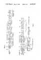
- FIG. 7shows a QAM modulator which may be used to practice the invention.
- FIG. 5shows a QAM demodulator which may be used to practice the invention.
- FIG. 1a normal 8 point contellation for a QAM signal mapped in the complex plane is shown.
- the originis unoccupied and the remaining data points are disposed on concentric rings.
- the maximum power requirement for such a constellationis a function of the distance from the origin 10 to the furthest mapped position 12.
- a secondary channelin introduced by virtue of a mapped data point 14 selecting one of two assigned positions, A or B.
- data point 14when data point 14 is located as shown in FIG. 1, only primary channel transmission occurs. However, shifting of the data point 14 to assume either of positions A or B results in secondary channel transmission.
- one of data point positions Ais assigned a binary "0" and the other of the positions is assigned a binary "1". If, for example, position A is assigned a binary "0" and position B a binary "1" then, data point 14 assuming the position A would result in the transmission of a "0" on the secondary channel and data point 14 assuming the position B would result in the transmission of a binary "1" on the secondary channel.
- the power requirement for the data point 14 assuming position A or Bwill be no greater than that already necessary for the furthest data point 12. This assumes that during secondary channel transmission the data point will be at position A half the time and at position B the other half of the time.
- the position of data point Bis conveniently chosen at the origin.
- the position of data point Amay assume any location up to 1.4 without exceeding the power requirements for data point 12.
- data point position Bis moved from the origin permitting data point position A to likewise be moved from the origin to a position in accordance with the above formula.
- transmission of the secondary channel in accordance with the present inventionis effected simply by shifting a single data point to one of two assigned positions. As a result, degradation of the primary signal is minimal.
- Modems for transmitting and receiving quadrature-amplitude modulated signalsare well known in the art.
- U.S. Pat. No. 3,955,141granted on May 4, 1976, to Lyon et al
- a modemis described for handling time-multiplexed signals.
- the transmitter and receiverare synchronized by changing the positions of a number preselected signal constellation points. These constellation points are shifted by the transmitter in response to an internally-generated frame signal.
- a modem similar to the one described by Lyon et al in the above mentioned U.S. Pat. No. 3,955,141may be used to transmit a modified QAM data point constellation for secondary channel signaling as follows.
- the transmitteras shown in FIG. 4, comprises a randomizer 20, an encoder 22 and a modulator 24.
- the input bits from a primary data line 18, i.e., the primary dataare fed into a randomizer which scrambles them in a pseudo-random fashion.
- the scrambled data bitsare then fed to encoder 22 through a serial-to-parallel converter 26.
- the encoderis provided to generate the real and imaginary signals X and Y which define the signal constellation points corresponding to a preselected number of data bits from randomizer 20.
- Encoder 22may include a differential encoder 28 for differentially encoding the bits in the normal manner. From encoder 28 the binary bits are then fed to a coordinate signal generator 30.
- the coordinate signal generatoris adapted to generate the X and Y signals in accordance with a preselected encoding scheme.
- the cordinate signal generator 30also receives a secondary data signal on line C which, when enabled forces the signal generator to change its signal constellation in accordance with binary signals from a second data line 32.
- the corresponding output signals X and Ymay be defined as shown in Table 1 to generate the signal constellation points of FIG. 2, X and Y corresponding to the in-phase and quadrature components of the QAM signals, respectively.
- each binary word A 0 , A 1 , A 2is shown in FIG. 2 in parenthesis. It can be seen from this Table, that except for primary input 111 the generator outputs are not affected by the secondary control signal and the binary data. For 111, if the secondary control signal is disabled, point (0,1) is selected. If the binary control signal is enabled, then generator 30 selects either point A (0,1.41) or point B (0,0) in response to primary input 111 depending in whether the secondary binary data signal is a "0" or a "1".
- the X and Y signals from encoder 22are fed to modulator 24 as shown.
- the modulatorcomprises low pass filters 34, 36, and multipliers 38 and 40.
- the two signalsare filtered and then multiplied by a sine and cosine signal at the carrier frequency fc.
- the multiplied signalsare added in summer 42.
- the output of modulator 24which comprises quadrature amplitude signals, are fed to a line interface circuit 44 which transfers the modulator output to a communication channel 46 via transformer 48.
- Quadrature amplitude signals from channel 46are transferred by transformer 50 to interface and signal conditioning circuits 52. From circuits 52 the incoming signals are fed to demodulator 54. In the demodulator the signals are multiplied by multipliers 56 and 58 by the sine and cosine of the carrier frequency and low pass filtered by filters 60 and 62. The filter outputs are fed to an analog-to-digital converter 64 and the output of the converter is fed to an equalizer 66. The output of the equalizer is fed to a decision circuit 68 which decides which ideal constellation point corresponds to a incoming QAM signal. The ideal constellation point is characterized by signals X and Y which are identical to the output of the modulator 24 in FIG. 4.
- the X and Y signalsare fed to a decoder 70.
- This decoderis a point decoder and is adapted to generate three primary binary signals on lines 74 and a secondary binary signal on line 76 for each received QAM signal. Of course if a received signal corresponds to point (0,1) then no secondary output is generated on line 76.
- the binary signals from lines 74are converted by a parallel-to-serial converter 78 so that its output is identical to the input of serial-to-parallel converter 26 of FIG. 4. This output is derandomized by derandomizer 80 to eliminate the effect of randomizer 20.
- the outputs of decoder 72are generated in conformance with Table 1 and the signal constellation of FIG. 2.
Landscapes
- Engineering & Computer Science (AREA)
- Computer Networks & Wireless Communication (AREA)
- Signal Processing (AREA)
- Digital Transmission Methods That Use Modulated Carrier Waves (AREA)
Abstract
Description
TABLE 1 ______________________________________ INPUTS OUTPUTS A.sub.0 A.sub.1 A.sub.2 C X Y ______________________________________ 0 0 0X 1 1 0 0 1 X 0 1 0 1 0 X -1 1 0 1 1 X -1 0 1 0 0 X -1 -1 1 0 1 X 0 -1 1 1 0 X -1 -1 1 1 0NONE 1 0 1 1 1 0 0 0 1 1 1 1 0 1.41 ______________________________________ X = DON'T CARE
Claims (5)
Priority Applications (1)
| Application Number | Priority Date | Filing Date | Title |
|---|---|---|---|
| US06/748,748US4630287A (en) | 1983-12-28 | 1985-06-25 | Secondary channel signalling in a QAM data point constellation |
Applications Claiming Priority (2)
| Application Number | Priority Date | Filing Date | Title |
|---|---|---|---|
| US56552383A | 1983-12-28 | 1983-12-28 | |
| US06/748,748US4630287A (en) | 1983-12-28 | 1985-06-25 | Secondary channel signalling in a QAM data point constellation |
Related Parent Applications (1)
| Application Number | Title | Priority Date | Filing Date |
|---|---|---|---|
| US56552383AContinuation-In-Part | 1983-12-28 | 1983-12-28 |
Publications (1)
| Publication Number | Publication Date |
|---|---|
| US4630287Atrue US4630287A (en) | 1986-12-16 |
Family
ID=27073887
Family Applications (1)
| Application Number | Title | Priority Date | Filing Date |
|---|---|---|---|
| US06/748,748Expired - LifetimeUS4630287A (en) | 1983-12-28 | 1985-06-25 | Secondary channel signalling in a QAM data point constellation |
Country Status (1)
| Country | Link |
|---|---|
| US (1) | US4630287A (en) |
Cited By (31)
| Publication number | Priority date | Publication date | Assignee | Title |
|---|---|---|---|---|
| US4860316A (en)* | 1987-02-19 | 1989-08-22 | Fujitsu Limited | Multilevel amplitude modulation and demodulation communication system |
| US4891806A (en)* | 1987-09-18 | 1990-01-02 | Racal Data Communications Inc. | Constellation multiplexed inband secondary channel for voiceband modem |
| US4894844A (en)* | 1987-06-12 | 1990-01-16 | Codex Corporation | Signal constellations |
| US4959842A (en)* | 1988-04-13 | 1990-09-25 | Codex Corporation | Signal constellations |
| US5036526A (en)* | 1987-08-10 | 1991-07-30 | Northern Telecom Limited | Method of communicating stuffing indications in a multi-level communications system |
| US5214641A (en)* | 1989-02-08 | 1993-05-25 | Silicon Systems, Inc. | Mixed analog digital secondary channel FSK modem |
| EP0506400A3 (en)* | 1991-03-27 | 1993-05-26 | Matsushita Electric Industrial Co., Ltd. | Signal transmission system |
| US5315617A (en)* | 1992-05-29 | 1994-05-24 | General Electric Company | QAM encoding for high-definition television system |
| WO1994021070A3 (en)* | 1993-03-02 | 1994-10-13 | Lukac Kuruc Eric | Method for increasing transmission rate |
| US5448555A (en)* | 1993-06-14 | 1995-09-05 | At&T Corp. | Simultaneous analog and digital communication |
| US5506866A (en)* | 1993-11-15 | 1996-04-09 | At&T Corp. | Side-channel communications in simultaneous voice and data transmission |
| EP0630128A3 (en)* | 1993-06-14 | 1997-05-02 | At & T Corp | Autorate method for simultaneous transmission of voice and data. |
| EP0630117A3 (en)* | 1993-06-14 | 1997-05-02 | At & T Corp | Trellis coding in a simultaneous voice and data system. |
| EP0630135A3 (en)* | 1993-06-14 | 1997-05-07 | At & T Corp | Simultaneous analog and digital communication using fractional rate encoding. |
| EP0630136A3 (en)* | 1993-06-14 | 1997-05-07 | At & T Corp | Simultaneous analog and digital communication with improved phase immunity. |
| US5710754A (en)* | 1992-01-14 | 1998-01-20 | Fujitsu Limited | Multiplex transmission system wherein analog signal is transformed to base band random-transformed and superimposed on dispersed signal points in vector signal space |
| US5710793A (en)* | 1995-12-21 | 1998-01-20 | National Semiconductor Corporation | Error signal quantization method and hardware for mixed blind and decision directed equalization |
| US6256357B1 (en) | 1992-03-26 | 2001-07-03 | Matsushita Electric Industrial Co., Ltd. | Communication system |
| US20030039348A1 (en)* | 1997-02-28 | 2003-02-27 | Gordon Bremer | Simultaneous transmission of an analog pots signal and a digital signal on a subscriber line |
| US6549716B1 (en) | 1992-03-26 | 2003-04-15 | Matsushita Electric Industrial Co., Ltd. | Communication system |
| USRE38483E1 (en) | 1992-03-26 | 2004-03-30 | Matsushita Electric Industrial Co., Ltd. | Communication system |
| US6724976B2 (en) | 1992-03-26 | 2004-04-20 | Matsushita Electric Industrial Co., Ltd. | Communication system |
| US6728467B2 (en) | 1992-03-26 | 2004-04-27 | Matsushita Electric Industrial Co., Ltd. | Communication system |
| US7158577B1 (en) | 1992-03-26 | 2007-01-02 | Matsushita Electric Industrial Co., Ltd. | Communication system |
| USRE39890E1 (en) | 1991-03-27 | 2007-10-23 | Matsushita Electric Industrial Co., Ltd. | Communication system |
| USRE39902E1 (en) | 1991-03-27 | 2007-10-30 | Matsushita Electric Industrial Co., Ltd. | Communication system |
| USRE39929E1 (en) | 1991-03-27 | 2007-11-27 | Matsushita Electric Industrial Co., Ltd. | Communication system |
| US7894541B2 (en) | 1992-03-26 | 2011-02-22 | Panasonic Corporation | Communication system |
| CN101547182B (en)* | 2009-04-17 | 2011-07-20 | 北京大学 | Method for mapping and demapping QAM constellation diagrams |
| USRE42643E1 (en) | 1991-03-27 | 2011-08-23 | Panasonic Corporation | Communication system |
| USRE43093E1 (en) | 1992-03-26 | 2012-01-10 | Panasonic Corporation | Communication system |
Citations (5)
| Publication number | Priority date | Publication date | Assignee | Title |
|---|---|---|---|---|
| US3060268A (en)* | 1958-05-19 | 1962-10-23 | Automatic Elect Lab | System for transmitting special signals for pulse type telecommunication systems |
| US4227152A (en)* | 1978-06-13 | 1980-10-07 | International Business Machines Corporation | Method and device for training an adaptive equalizer by means of an unknown data signal in a quadrature amplitude modulation transmission system |
| US4347616A (en)* | 1979-07-31 | 1982-08-31 | Nippon Electric Co., Ltd. | Digital multi-level multi-phase modulation communication system |
| US4389722A (en)* | 1979-09-13 | 1983-06-21 | Licentia Patent-Verwaltungs-Gmbh | Method for the simultaneous transmission of a plurality of data stream over one transmission channel |
| US4525846A (en)* | 1982-12-27 | 1985-06-25 | Paradyne Corporation | Modem in-band secondary channel via radial modulation |
- 1985
- 1985-06-25USUS06/748,748patent/US4630287A/ennot_activeExpired - Lifetime
Patent Citations (5)
| Publication number | Priority date | Publication date | Assignee | Title |
|---|---|---|---|---|
| US3060268A (en)* | 1958-05-19 | 1962-10-23 | Automatic Elect Lab | System for transmitting special signals for pulse type telecommunication systems |
| US4227152A (en)* | 1978-06-13 | 1980-10-07 | International Business Machines Corporation | Method and device for training an adaptive equalizer by means of an unknown data signal in a quadrature amplitude modulation transmission system |
| US4347616A (en)* | 1979-07-31 | 1982-08-31 | Nippon Electric Co., Ltd. | Digital multi-level multi-phase modulation communication system |
| US4389722A (en)* | 1979-09-13 | 1983-06-21 | Licentia Patent-Verwaltungs-Gmbh | Method for the simultaneous transmission of a plurality of data stream over one transmission channel |
| US4525846A (en)* | 1982-12-27 | 1985-06-25 | Paradyne Corporation | Modem in-band secondary channel via radial modulation |
Cited By (84)
| Publication number | Priority date | Publication date | Assignee | Title |
|---|---|---|---|---|
| US4860316A (en)* | 1987-02-19 | 1989-08-22 | Fujitsu Limited | Multilevel amplitude modulation and demodulation communication system |
| US4894844A (en)* | 1987-06-12 | 1990-01-16 | Codex Corporation | Signal constellations |
| US5036526A (en)* | 1987-08-10 | 1991-07-30 | Northern Telecom Limited | Method of communicating stuffing indications in a multi-level communications system |
| US4891806A (en)* | 1987-09-18 | 1990-01-02 | Racal Data Communications Inc. | Constellation multiplexed inband secondary channel for voiceband modem |
| US4959842A (en)* | 1988-04-13 | 1990-09-25 | Codex Corporation | Signal constellations |
| US5214641A (en)* | 1989-02-08 | 1993-05-25 | Silicon Systems, Inc. | Mixed analog digital secondary channel FSK modem |
| EP0975169A1 (en)* | 1991-03-27 | 2000-01-26 | Matsushita Electric Industrial Co., Ltd. | Signal transmission system |
| USRE40134E1 (en) | 1991-03-27 | 2008-03-04 | Matsushita Electric Industrial Co., Ltd. | Communication system |
| USRE41001E1 (en) | 1991-03-27 | 2009-11-24 | Panasonic Corporation | Communication system |
| USRE40978E1 (en) | 1991-03-27 | 2009-11-17 | Panasonic Corporation | Communication system |
| USRE40779E1 (en) | 1991-03-27 | 2009-06-23 | Panasonic Corporation | Communication system |
| USRE40701E1 (en) | 1991-03-27 | 2009-04-14 | Panasonic Corporation | Communication system |
| US5555275A (en)* | 1991-03-27 | 1996-09-10 | Matsushita Electric Industrial Co., Ltd. | Multi-threshold and hierarchical television signal transmission system |
| USRE40255E1 (en) | 1991-03-27 | 2008-04-22 | Matsushita Electric Industrial Co., Ltd. | Communication system |
| USRE40256E1 (en) | 1991-03-27 | 2008-04-22 | Matsushita Electrical Industrial Co., Ltd. | Communication system |
| USRE40241E1 (en) | 1991-03-27 | 2008-04-15 | Matsushita Electric Industrial Co., Ltd. | Communication system |
| USRE40242E1 (en) | 1991-03-27 | 2008-04-15 | Matsushita Electric Industrial Co., Ltd. | Communication system |
| USRE40206E1 (en) | 1991-03-27 | 2008-04-01 | Matsushita Electric Industrial Co., Ltd. | Communication system |
| EP1359761A3 (en)* | 1991-03-27 | 2006-01-18 | Matsushita Electric Industrial Co., Ltd. | Signal transmission system |
| USRE40175E1 (en) | 1991-03-27 | 2008-03-25 | Matsushita Electric Industrial Co., Ltd. | Communication system |
| USRE40174E1 (en) | 1991-03-27 | 2008-03-25 | Matsushita Electric Industrial Co., Ltd. | Communication system |
| USRE42643E1 (en) | 1991-03-27 | 2011-08-23 | Panasonic Corporation | Communication system |
| USRE39956E1 (en) | 1991-03-27 | 2007-12-25 | Matsushita Electric Industrial Co., Ltd. | Communication system |
| USRE39928E1 (en) | 1991-03-27 | 2007-11-27 | Matsushita Electric Industrial Co., Ltd. | Communication system |
| EP0973335A1 (en)* | 1991-03-27 | 2000-01-19 | Matsushita Electric Industrial Co., Ltd. | Signal transmission system |
| EP0766478A3 (en)* | 1991-03-27 | 2000-01-19 | Matsushita Electric Industrial Co., Ltd. | Signal transmission system |
| EP0975174A1 (en)* | 1991-03-27 | 2000-01-26 | Matsushita Electric Industrial Co., Ltd. | Signal transmission system |
| EP0506400A3 (en)* | 1991-03-27 | 1993-05-26 | Matsushita Electric Industrial Co., Ltd. | Signal transmission system |
| EP0975172A1 (en)* | 1991-03-27 | 2000-01-26 | Matsushita Electric Industrial Co., Ltd. | Signal transmission system |
| EP0975170A1 (en)* | 1991-03-27 | 2000-01-26 | Matsushita Electric Industrial Co., Ltd. | Signal transmission system |
| EP1049334A1 (en)* | 1991-03-27 | 2000-11-02 | Matsushita Electric Industrial Co., Ltd. | Signal transmission system |
| USRE39927E1 (en) | 1991-03-27 | 2007-11-27 | Matsushita Electric Industrial Co., Ltd. | Communication system |
| USRE39890E1 (en) | 1991-03-27 | 2007-10-23 | Matsushita Electric Industrial Co., Ltd. | Communication system |
| USRE39929E1 (en) | 1991-03-27 | 2007-11-27 | Matsushita Electric Industrial Co., Ltd. | Communication system |
| USRE39902E1 (en) | 1991-03-27 | 2007-10-30 | Matsushita Electric Industrial Co., Ltd. | Communication system |
| US6298036B1 (en) | 1992-01-14 | 2001-10-02 | Fujitsu Limited | Multiplex transmission system wherein analog signal is transformed to base band, random-transformed and superimposed on dispersed signal points in vector signal space |
| US5710754A (en)* | 1992-01-14 | 1998-01-20 | Fujitsu Limited | Multiplex transmission system wherein analog signal is transformed to base band random-transformed and superimposed on dispersed signal points in vector signal space |
| US7146092B2 (en) | 1992-03-19 | 2006-12-05 | Matsushita Electric Industrial Co., Ltd. | Communication system |
| US20050018785A1 (en)* | 1992-03-26 | 2005-01-27 | Mitsuaki Oshima | Communication system |
| USRE40936E1 (en) | 1992-03-26 | 2009-10-13 | Panasonic Corporation | Communication system |
| US20040126088A1 (en)* | 1992-03-26 | 2004-07-01 | Mitsuaki Oshima | Communication system |
| US20040127166A1 (en)* | 1992-03-26 | 2004-07-01 | Mitsuaki Oshima | Communication system |
| US6728467B2 (en) | 1992-03-26 | 2004-04-27 | Matsushita Electric Industrial Co., Ltd. | Communication system |
| US8160173B2 (en) | 1992-03-26 | 2012-04-17 | Panasonic Corporation | Communication system |
| US6724976B2 (en) | 1992-03-26 | 2004-04-20 | Matsushita Electric Industrial Co., Ltd. | Communication system |
| USRE43093E1 (en) | 1992-03-26 | 2012-01-10 | Panasonic Corporation | Communication system |
| USRE39111E1 (en) | 1992-03-26 | 2006-05-30 | Matsushita Electric Industrial Co., Ltd. | Communication system |
| USRE38483E1 (en) | 1992-03-26 | 2004-03-30 | Matsushita Electric Industrial Co., Ltd. | Communication system |
| US7158577B1 (en) | 1992-03-26 | 2007-01-02 | Matsushita Electric Industrial Co., Ltd. | Communication system |
| US7280806B2 (en) | 1992-03-26 | 2007-10-09 | Matsushita Electric Industrial Co., Ltd. | Communication system |
| US7894541B2 (en) | 1992-03-26 | 2011-02-22 | Panasonic Corporation | Communication system |
| US6549716B1 (en) | 1992-03-26 | 2003-04-15 | Matsushita Electric Industrial Co., Ltd. | Communication system |
| USRE41146E1 (en) | 1992-03-26 | 2010-02-23 | Panasonic Corporation | Communication system |
| US6256357B1 (en) | 1992-03-26 | 2001-07-03 | Matsushita Electric Industrial Co., Ltd. | Communication system |
| US7302007B1 (en) | 1992-03-26 | 2007-11-27 | Matsushita Electric Industrial Co., Ltd. | Communication system |
| USRE41004E1 (en) | 1992-03-26 | 2009-11-24 | Panasonic Corporation | Communication system |
| USRE41003E1 (en) | 1992-03-26 | 2009-11-24 | Panasonic Corporation | Communication system |
| US20040086056A1 (en)* | 1992-03-26 | 2004-05-06 | Mitsuaki Oshima | Communication system |
| US7542729B2 (en) | 1992-03-26 | 2009-06-02 | Panasonic Corporation | Communication system |
| US7496146B2 (en) | 1992-03-26 | 2009-02-24 | Panasonic Corporation | Communication system |
| US7362813B2 (en) | 1992-03-26 | 2008-04-22 | Matsushita Electric Industrial Co., Ltd. | Communication system |
| US7352822B2 (en) | 1992-03-26 | 2008-04-01 | Matsushita Electric Industrial Co., Ltd. | Telephone for transmitting an uplink signal to a base station and for receiving first and second downlink signals from the base station, and a base station for receiving an uplink signal from a telephone and transmitting first and second downlink signals to the telephone |
| US5315617A (en)* | 1992-05-29 | 1994-05-24 | General Electric Company | QAM encoding for high-definition television system |
| US5734682A (en)* | 1993-03-02 | 1998-03-31 | Lukac-Kuruc; Eric | Method for increasing transmission rate |
| WO1994021070A3 (en)* | 1993-03-02 | 1994-10-13 | Lukac Kuruc Eric | Method for increasing transmission rate |
| BE1006904A3 (en)* | 1993-03-02 | 1995-01-24 | Lukac Kuruc Eric | Method for the transmission of information on electrical support. |
| US5859877A (en)* | 1993-06-14 | 1999-01-12 | Paradyne Corporation | Simultaneous analog and digital communication using fractional rate encoding |
| EP0630136A3 (en)* | 1993-06-14 | 1997-05-07 | At & T Corp | Simultaneous analog and digital communication with improved phase immunity. |
| EP0630117A3 (en)* | 1993-06-14 | 1997-05-02 | At & T Corp | Trellis coding in a simultaneous voice and data system. |
| US5844944A (en)* | 1993-06-14 | 1998-12-01 | Paradyne Corporation | Simultaneous analog and digital communication using partitioning of bits into words |
| US5448555A (en)* | 1993-06-14 | 1995-09-05 | At&T Corp. | Simultaneous analog and digital communication |
| US5661718A (en)* | 1993-06-14 | 1997-08-26 | Lucent Technologies Inc. | Simultaneous analog and digital communication |
| EP0630135A3 (en)* | 1993-06-14 | 1997-05-07 | At & T Corp | Simultaneous analog and digital communication using fractional rate encoding. |
| EP0630128A3 (en)* | 1993-06-14 | 1997-05-02 | At & T Corp | Autorate method for simultaneous transmission of voice and data. |
| US5881047A (en)* | 1993-06-14 | 1999-03-09 | Paradyne Corporation | Simultaneous analog and digital communication with improved phase immunity |
| US5506866A (en)* | 1993-11-15 | 1996-04-09 | At&T Corp. | Side-channel communications in simultaneous voice and data transmission |
| US5710793A (en)* | 1995-12-21 | 1998-01-20 | National Semiconductor Corporation | Error signal quantization method and hardware for mixed blind and decision directed equalization |
| US20070286187A1 (en)* | 1997-02-28 | 2007-12-13 | Gordon Bremer | Apparatus and Method for Simultaneous Multiple Telephone Type Services on a Single Telephone Line |
| US6580785B2 (en) | 1997-02-28 | 2003-06-17 | Paradyne Corporation | Apparatus and method for simultaneous multiple telephone type services on a single telephone line |
| US7961850B2 (en) | 1997-02-28 | 2011-06-14 | Paradyne Corporation | Apparatus and method for simultaneous multiple telephone type services on a single telephone line |
| US20030039348A1 (en)* | 1997-02-28 | 2003-02-27 | Gordon Bremer | Simultaneous transmission of an analog pots signal and a digital signal on a subscriber line |
| US7020266B2 (en) | 1997-02-28 | 2006-03-28 | Paradyne Corporation | Simultaneous transmission of an analog pots signal and a digital signal on a subscriber line |
| US20050163303A1 (en)* | 1997-02-28 | 2005-07-28 | Gordon Bremer | Apparatus and method for simultaneous multiple telephone type services on a single telephone line |
| CN101547182B (en)* | 2009-04-17 | 2011-07-20 | 北京大学 | Method for mapping and demapping QAM constellation diagrams |
Similar Documents
| Publication | Publication Date | Title |
|---|---|---|
| US4630287A (en) | Secondary channel signalling in a QAM data point constellation | |
| US5105443A (en) | Inband coding of secondary data | |
| EP0134101B1 (en) | Differentially nonlinear convolutional channel coding with expanded set of signalling alphabets | |
| US4271527A (en) | Double side band-quadrature carrier modulation signal structures | |
| US4965641A (en) | Processor modem | |
| US4660214A (en) | QANI Trellis-coded signal structure | |
| US5142552A (en) | Method and apparatus for analog D.C. offset cancellation | |
| US4630286A (en) | Device for synchronization of multiple telephone circuits | |
| US4882726A (en) | Full duplex modem system for differing data bit rates | |
| US4525846A (en) | Modem in-band secondary channel via radial modulation | |
| US4627077A (en) | Modified QAM data point constellation for secondary channel signalling | |
| CA2085272A1 (en) | Partial-response-channel precoding | |
| US3906347A (en) | Transversal equalizer for use in double sideband quadrature amplitude modulated system | |
| US4734920A (en) | High speed modem for multiple communication circuits | |
| DK0562875T3 (en) | Multi-resolution QAM system. | |
| US3988539A (en) | Data transmission system using optimal eight-vector signaling scheme | |
| US4857858A (en) | Digital demodulation system having independently operating cross-polarization cancellers | |
| US4716385A (en) | Multilevel modulator comprising a compact error correcting code producing unit | |
| GB2207583A (en) | Method and apparatus for transmitting data over a channel | |
| US4644537A (en) | Inband coding of secondary data | |
| US5187711A (en) | Error correction method for multicarrier radio transmission system | |
| JPS61294952A (en) | Digital data decoder and digital data transmission | |
| EP0383349B1 (en) | A method of arranging signal points in a quadrature amplitude modulation/demodulation system | |
| US4646325A (en) | Index decoder for digital modems | |
| CA2022153C (en) | Modulator and demodulator for data transmission systems |
Legal Events
| Date | Code | Title | Description |
|---|---|---|---|
| STCF | Information on status: patent grant | Free format text:PATENTED CASE | |
| FEPP | Fee payment procedure | Free format text:PAYOR NUMBER ASSIGNED (ORIGINAL EVENT CODE: ASPN); ENTITY STATUS OF PATENT OWNER: LARGE ENTITY | |
| FPAY | Fee payment | Year of fee payment:4 | |
| FPAY | Fee payment | Year of fee payment:8 | |
| AS | Assignment | Owner name:PARADYNE CORPORATION (FORMERLY KNOWN AS AT&T PARAD Free format text:ASSIGNMENT OF ASSIGNORS INTEREST;ASSIGNOR:LUCENT TECHNOLOGIES, INC.;REEL/FRAME:008167/0408 Effective date:19960731 | |
| AS | Assignment | Owner name:BANKAMERICA BUSINESS CREDIT, INC., CALIFORNIA Free format text:SECURITY AGREEMENT;ASSIGNOR:PARADYNE CORPORATION;REEL/FRAME:008261/0384 Effective date:19960731 | |
| FPAY | Fee payment | Year of fee payment:12 | |
| SULP | Surcharge for late payment | ||
| AS | Assignment | Owner name:FOOTHILL CAPITAL CORPORATION, CALIFORNIA Free format text:SECURITY AGREEMENT;ASSIGNOR:PARADYNE CORPORATION;REEL/FRAME:012211/0350 Effective date:20010716 | |
| AS | Assignment | Owner name:PARADYNE CORPORATION, FLORIDA Free format text:RELEASE OF SECURITY INTEREST;ASSIGNOR:WELLS FARGO FOOTHILL, INC. F/K/A FOOTHILL CAPITAL CORPORATION;REEL/FRAME:015603/0205 Effective date:20041216 | |
| AS | Assignment | Owner name:PARADYNE CORPORATION, FLORIDA Free format text:ASSIGNMENT OF ASSIGNORS INTEREST;ASSIGNORS:BANK OF AMERICA, N.A.;BANKAMERICA BUSINESS CREDIT, INC.;REEL/FRAME:015797/0535 Effective date:20040722 | |
| AS | Assignment | Owner name:PIRIN POCKET DATA LLC, NEVADA Free format text:ASSIGNMENT OF ASSIGNORS INTEREST;ASSIGNOR:PARADYNE CORPORATION;REEL/FRAME:017297/0726 Effective date:20050202 | |
| AS | Assignment | Owner name:PARADYNE CORPORATION,FLORIDA Free format text:ASSIGNMENT OF ASSIGNORS INTEREST;ASSIGNOR:ARMSTRONG, THOMAS R.;REEL/FRAME:024129/0689 Effective date:19810824 |