US4628935A - Defibrillator adapted for use with accessory cassettes - Google Patents
Defibrillator adapted for use with accessory cassettesDownload PDFInfo
- Publication number
- US4628935A US4628935AUS06/689,746US68974685AUS4628935AUS 4628935 AUS4628935 AUS 4628935AUS 68974685 AUS68974685 AUS 68974685AUS 4628935 AUS4628935 AUS 4628935A
- Authority
- US
- United States
- Prior art keywords
- electrode
- defibrillator
- contact
- electrodes
- adapter
- Prior art date
- Legal status (The legal status is an assumption and is not a legal conclusion. Google has not performed a legal analysis and makes no representation as to the accuracy of the status listed.)
- Expired - Lifetime
Links
- 230000035939shockEffects0.000claimsdescription4
- 238000005192partitionMethods0.000description14
- 239000004020conductorSubstances0.000description11
- 238000004146energy storageMethods0.000description5
- 235000014676Phragmites communisNutrition0.000description4
- 238000000034methodMethods0.000description3
- 230000000747cardiac effectEffects0.000description2
- 210000000038chestAnatomy0.000description2
- 230000000881depressing effectEffects0.000description2
- 206010003658Atrial FibrillationDiseases0.000description1
- 208000003443UnconsciousnessDiseases0.000description1
- 239000000853adhesiveSubstances0.000description1
- 230000001070adhesive effectEffects0.000description1
- 210000003109clavicleAnatomy0.000description1
- 238000010586diagramMethods0.000description1
- 238000007599dischargingMethods0.000description1
- 239000011810insulating materialSubstances0.000description1
- 230000011664signalingEffects0.000description1
- 230000005236sound signalEffects0.000description1
- 210000001562sternumAnatomy0.000description1
- 238000001356surgical procedureMethods0.000description1
- 230000001225therapeutic effectEffects0.000description1
- 230000001960triggered effectEffects0.000description1
- 208000003663ventricular fibrillationDiseases0.000description1
Images


Classifications
- A—HUMAN NECESSITIES
- A61—MEDICAL OR VETERINARY SCIENCE; HYGIENE
- A61N—ELECTROTHERAPY; MAGNETOTHERAPY; RADIATION THERAPY; ULTRASOUND THERAPY
- A61N1/00—Electrotherapy; Circuits therefor
- A61N1/18—Applying electric currents by contact electrodes
- A61N1/32—Applying electric currents by contact electrodes alternating or intermittent currents
- A61N1/38—Applying electric currents by contact electrodes alternating or intermittent currents for producing shock effects
- A61N1/39—Heart defibrillators
- A61N1/3904—External heart defibrillators [EHD]
Definitions
- the present inventionrelates to defibrillators and, in particular, to a defibrillator that is adapted for use with accessory cassettes.
- a defibrillatoris a therapeutic instrument that is useful in curing certain cardiac irregularities, particular ventricular fibrillation and atrial fibrillation.
- the defibrillatortypically includes a pair of large paddle electrodes, and operates to apply a high energy DC pulse to a patient through the paddle electrodes when appropriately triggered by an operator.
- the paddle electrodesare held in the operator's hands when the defibrillation pulse is administered.
- one paddle electrodeis placed lateral to the upper sternum and below the right clavicle on the patient's right chest, and the second paddle electrode is placed on the patient's lower left chest, usually just below and lateral to the cardiac apex.
- anterior paddle electrodeIn a second known arrangement (anterior/posterior), the anterior paddle electrode is placed over the precordium, and the posterior paddle electrode is placed on the patient's back behind the heart. Since a patient will usually be unconscious and lying on his or her back, the size of a paddle electrode and the requirement that it be held by the operator generally make the anterior/posterior technique impractical when only paddle electrodes are available.
- defibrillator electrodesinclude internal electrodes and low-profile disposable electrodes.
- Internal electrodesare small electrodes that are used during surgery when the heat is exposed, and are applied directly to the heart.
- Disposable electrodesare flat, low-profile electrodes that include adhesive so that the electrode can be secured to a patient's skin. Unlike a paddle electrode, a disposable electrode can be applied to a patient's back, permitting the use of the somewhat more efficient anterior/posterior defibrillation technique.
- the use of disposable electrodesalso permits the electrodes to remain attached to a patient while the patient is moved, e.g., while the patient is moved from an ambulance into an emergency room, thereby permitting a faster response should defibrillation subsequently be needed.
- defibrillatorshave accommodated different types of electrodes by providing a set of external connectors to which the different electrodes could be electrically connected.
- the disadvantage of such an arrangementis that the paddle electrodes are not always available for use. Furthermore, such an arrangement gives rise to the possibility that the defibrillator will be left in a state in which no electrodes are attached or available.
- the present inventionprovides a defibrillator adapted for use with an accessory device such as an accessory cassette adapter for connecting an accessory electrode set to a defibrillator.
- the defibrillatorcomprises a body, a pair of electrodes, means for mounting the electrodes to the body, connector means for mounting an accessory device to the body, and contact means.
- Each electrodeincludes an electrode element adapted for application to a patient and through which a defibrillation shock may be delivered to the patient.
- the contact meanselectrically connects the electrode elements to the accessory device when the accessory device is mounted to the body.
- the defibrillatormay further comprise a test load, and the contact means may be adapted to electrically connect the test load to the electrode elements when the accessory device is not mounted to the body and to break the electrical connection between the test load and the electrodes when the accessory device is mounted to the body.
- the accessory devicemay comprise an adapter for connecting accessory electrodes to the defibrillator, or a pacemaker.
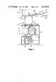
- FIG. 1is a front elevational view of a defibrillator, accessory cassette and electrode set
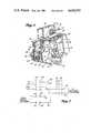
- FIG. 2is a cut away perspective view showing a portion of the defibrillator, accessory cassette and electrode set;
- FIG. 3is a side elevational view of one paddle electrode
- FIG. 4is a partially cut away perspective view showing the accessory cassette mounted to the defibrillator.
- FIG. 5is an electrical diagram of one embodiment of the accessory cassette.
- FIG. 1illustrates defibrillator 10 that is adapted to receive cassette 40.
- Defibrillator 10comprises body 12 and paddle electrodes 14 and 16.
- the upper, front portion of body 12is shaped to form recess 18, recess 18 being dimensioned to receive paddle electrodes 14 and 16 for stowing the paddle electrodes when they are not in use.
- Paddle electrodes 14 and 16are electrically connected to defibrillator 10 by means of cables 20 and 22 respectively.
- Paddle electrode 14includes discharge switch 24 and handle 26.
- Paddle electrode 16includes discharge switch 28, handle 30, charge switch 32 and charge indicator 34.
- the operatordepresses charge switch 32 to initiate charging of the defibrillator's energy storage means. While the energy storage means is charging, charge indicator 34 blinks on and off. When the energy storage means is fully charged, charge indicator 34 blinks steadily on.
- the operatormay then grip paddle electrodes 14 and 16 by means of handles 26 and 30 respectively, remove the paddle electrodes from recess 18, and then deliver a defibrillation shock by applying the paddle electrodes to a patient and simultaneously depressing discharge switches 24 and 28.
- the defibrillator of the present inventionis adapted to receive cassette 40 that may be used to connect additional electrodes to the defibrillator, or for other purposes as described below.
- Cassette 40comprises housing 42 depending tongue 44, and forwardly extending guard 46 (FIG. 2).
- cassette 40is adapted to receive a set of disposable electrodes illustrated schematically by electrode set 50.
- Electrode set 50comprises connector 52, cables 54 and 56, and disposable electrodes 58 and 60.
- Connector 52plugs into a matching connector 53 (FIG. 4) in the side of body 42 of cassette 40.
- Tongue 44is adapted to be received in a recess in housing 12 immediately behind recess 18.
- electric current for disposable electrodes 58 and 60is supplied through paddle electrodes 14 and 16. Thus the use of disposable electrodes does not require disconnection of the paddle electrodes, and the paddle electrodes are always available for use.
- paddle electrode 16comprises body 62, retainer plate 64 underlying the body, and electrode element 66 underlying the retainer plate. Electrode element 66 is the conductor through which electrical energy flows to the patient. The portion of body 62 immediately above retainer plate 64 is indented to form recess 68 that extends around the entire periphery of paddle electrode 16. At the lower end of the paddle electrode, magnet 70 is mounted in recess 68 by means of flange 72 that extends upward from the lower edge of retainer plate 64. The purpose of magnet 70 is described below. When electrode 16 is stowed in recess 18, the paddle electrode is secured against lateral motion by central guide 74 and edge guide 76.
- Central guide 74 and edge guide 76extend outward from partition 78 that forms the rear wall of recess 18.
- Central guide 74extends in a forward direction from partition 78, and includes lateral projections 80 and 82 that are parallel to but spaced from the forward surface of partition 78.
- Edge guide 76extends outwardly from partition 78, and includes projection 84 that is also parallel to but spaced from the outer surface of partition 78.
- Paddle electrode 16is stowed in recess 18 by sliding the paddle electrode downward, with electrode element 66 abutting partition 78, such that the lateral edges of retainer plate 64 slide under projections 82 and 84, and such that the projections are received within recess 68 of the paddle electrode.
- a second edge guide(not shown) is positioned to the left of central guide 74, and paddle electrode 14 is stowed between such other edge guide and central guide 74 in a manner similar to that described for paddle electrode 16.
- Defibrillator 10includes test load 90 that may be used to test the operation of the defibrillator. Such a test is performed by charging the defibrillator's energy storage means, and then discharging the energy storage means through the test load via paddle electrodes 14 and 16. As is well known to those skilled in the art, the results of such a test can be monitored by the defibrillator and can be used to confirm that the defibrillator is in good working order. Test load 90 is mounted to partition 92 that is positioned within the defibrillator a short distance behind partition 78.
- Paddle electrode 14may be electrically connected to test load 90 by means of conductors 94 and 96 positioned between partitions 78 and 92.
- Conductor 94is electrically connected to test load 90 by means of bolt 98 that passes through partition 92 and that also serves to support conductor 94 and test load 90.
- the forward part of conductor 94includes spring arm 100 that has electrical contact 102 mounted in a forward facing direction at its lower end.
- Conductor 96is mounted to the rear surface of partition 78, and includes rearwardly extending spring arm 104 that includes rearwardly facing contact 106 at its lower end.
- Conductor 96also includes contact 108 that extends through opening 110 in partition 78. The spring force of spring arms 100 and 104 are sufficient to maintain contacts 102 and 106 in electrical contact with one another.
- FIG. 2illustrates contact 112 that extends through opening 114 in partition 78 and that is adapted to make contact with electrode element 66 of paddle electrode 16 when the paddle electrode is stowed in recess 18.
- tongue 44 of cassette 40is a hollow member that comprises forward surface 120 and rear surface 124.
- Forward surface 120includes openings 126 and 128 behind which electrical contacts 130 and 132 respectively are positioned.
- Tongue 44further comprises edge connector socket 134 that faces downward into a channel formed in the lower portion of rear surface 124.
- Appropriate conductorsextend upward from electrical contacts 130 and 132 and from edge connector socket 134 to connector 53 in housing 42.
- Tongue 44is adapted to be inserted in cavity 136 that is formed between partitions 78 and 92.
- the top of cavity 136is closed by door 138 that is pivotally mounted by hinges 140 to rod 142.
- Door 138is biased by springs (not shown) into the closed position indicated in FIG. 2.
- the interior of cavity 136includes upwardly facing edge connector 144.
- FIG. 4illustrates the defibrillator and cassette of the present invention with tongue 44 of the cassette fully inserted into cavity 136.
- the lower portion of tongue 44is inserted between conductors 94 and 96, such that the electrical contact between contacts 102 and 106 is broken.
- Contact 106now makes electrical contact to contact 130 of tongue 44.
- Contact 102makes contact with lower rear surface 124 of tongue 44.
- the lower rear surfaceis fabricated from an insulating material, and as result test load 90 is now electrically isolated from the remainder of the defibrillator.
- edge connector 144is inserted into edge connector socket 134, thereby making appropriate electrical connections between cassette 40 and defibrillator 10.
- FIG. 4also illustrates reed switch 146 positioned immediately below lower wall 36 of recess 18.
- reed switch 146When paddle electrode 16 is stowed in recess 18, the presence of magnet 70 is sensed by reed switch 146, resulting in an electrical signal that may be used by the defibrillator, as described below, to determine that the paddle electrode has been stowed.
- a similar reed switch(not shown) is positioned beneath the left hand side of lower wall 36 and is used for sensing the presence of paddle electrode 14.
- FIG. 5illustrates the electrical connections made through cassette 40.
- Edge connector 144 of defibrillator 10includes four lines, sense lines S1, S2 and S3 and ground line GND.
- edge connector 144When cassette 40 is inserted into defibrillator 10, edge connector 144 is connected to edge connector socket 134 in the cassette.
- Edge connector socket 134grounds sense line S3, thereby signaling the defibrillator of the presence of cassette 40.
- Sense lines S1 and S2 and ground line GNDare conducted to connector 53 by lines 148-150 respectively.
- electrical contactis established between contact 106 of conductor 96 and contact 130 in the cassette.
- a similar electrical contactis made between contact 107 (not shown in FIGS. 1-4) and contact 132 of the cassette.
- Contacts 130 and 132are connected to connector 53 by lines 151 and 152.
- connector 52 of the electrode setis plugged into connector 53 of the cassette.
- Connector 52may ground either or both of sense lines S1 and S2, thereby providing information to the defibrillator concerning the nature of the electrode set attached to the cassette. In the embodiment illustrated in FIG. 5, connector 52 grounds sense line S2.
- Connector 52also establishes contact between lines 151 and 152 and cables 54 and 56 respectively, to thereby complete the connection between the paddle electrodes and the accessory electrode set.
- the information provided by the grounding of sense lines S1 and/or S2may be used by the defibrillator to limit the energy that may be selected by the operator.
- the defibrillatormay limit energy selection to 50 joules for internal electrodes and 360 joules for disposable electrodes.
- the defibrillatormay also include logic that will block all discharges when the paddle electrodes have been stowed and sense line S3 has been grounded, unless one of sense lines S1 and S2 has also been grounded, indicating the presence of an accessory electrode set. The stowing of the paddle electrodes is sensed through the magnetic reed switches described above.
- Defibrillation through accessory paddlesis always accomplished by means of discharge switches 24 and 28 in paddle electrodes 14 and 16 when the paddle electrodes are stowed in recess 18. Discharge into the test load is also accomplished by depressing discharge switches 24 and 28 with the paddle electrodes stowed. Guard 46 of cassette 40 is therefore provided to prevent accidental discharge of the defibrillator through accessory electrodes when a test load discharge is intended.
- guard 46When cassette 40 is inserted into defibrillator 10, guard 46 is positioned over discharge switches 24 and 28. With the guard so positioned, access to the discharge switches (with the paddle electrodes stowed) is partially blocked. More operator attention is therefore required in order to discharge the defibrillator under such conditions, and the possibility of accidental discharge through accessory electrodes is therefore minimized.
- the cassette feature of the defibrillatormay be used to connect other devices to the defibrillator.
- cassette 40could comprise a pacemaker that was electrically connected to the defibrillator via edge connector socket 134 and edge connector 144.
- contacts 130 and 132would not be present, and the tongue of the cassette would simply break the connection between the paddle electrodes and the test load.
- Electrode set 50would then comprise an appropriate pacing electrode set, and guard 46 would be unnecessary and could be eliminated.
- electronic displays and controls required for pacing logic and pacing current generationwould be principally contained within the cassette.
- the cassettewould be supported by power supplies and electrical interfaces provided by the defibrillator.
- edge connector socket 134 and edge connector 144could be adapted to provide the following typical output signals from the cassette to the defibrillator; demand mode selected; nondemand mode selected; audio signal; eyeclose signal; pacing activated; electrodes off; pace rate and pace current.
- Input signals from the defibrillator to the cassettecould include an ECG valid signal and a sync pulse for use in demand pacing.
Landscapes
- Health & Medical Sciences (AREA)
- Cardiology (AREA)
- Heart & Thoracic Surgery (AREA)
- Engineering & Computer Science (AREA)
- Biomedical Technology (AREA)
- Nuclear Medicine, Radiotherapy & Molecular Imaging (AREA)
- Radiology & Medical Imaging (AREA)
- Life Sciences & Earth Sciences (AREA)
- Animal Behavior & Ethology (AREA)
- General Health & Medical Sciences (AREA)
- Public Health (AREA)
- Veterinary Medicine (AREA)
- Electrotherapy Devices (AREA)
Abstract
Description
Claims (4)
Priority Applications (1)
| Application Number | Priority Date | Filing Date | Title |
|---|---|---|---|
| US06/689,746US4628935A (en) | 1985-01-08 | 1985-01-08 | Defibrillator adapted for use with accessory cassettes |
Applications Claiming Priority (1)
| Application Number | Priority Date | Filing Date | Title |
|---|---|---|---|
| US06/689,746US4628935A (en) | 1985-01-08 | 1985-01-08 | Defibrillator adapted for use with accessory cassettes |
Publications (1)
| Publication Number | Publication Date |
|---|---|
| US4628935Atrue US4628935A (en) | 1986-12-16 |
Family
ID=24769757
Family Applications (1)
| Application Number | Title | Priority Date | Filing Date |
|---|---|---|---|
| US06/689,746Expired - LifetimeUS4628935A (en) | 1985-01-08 | 1985-01-08 | Defibrillator adapted for use with accessory cassettes |
Country Status (1)
| Country | Link |
|---|---|
| US (1) | US4628935A (en) |
Cited By (31)
| Publication number | Priority date | Publication date | Assignee | Title |
|---|---|---|---|---|
| US4915109A (en)* | 1988-09-23 | 1990-04-10 | Physio-Control Corporation | Defibrillator electrode adaptor |
| US4974600A (en)* | 1989-07-18 | 1990-12-04 | Reyes Rey S | Interface cable for connecting bedside electrocardiograph monitor to portable defibrillator/electrocardiograph machine |
| US5105821A (en)* | 1989-07-18 | 1992-04-21 | Reyes Rey S | Interface cable for connecting bedside electrocardiograph monitor to portable defibrillator/electrocardiograph machine |
| WO1993016757A1 (en)* | 1992-02-21 | 1993-09-02 | Zmd Corporation | Connection between transcutaneous pacing and defibrillation circuitry |
| US5249573A (en)* | 1992-02-21 | 1993-10-05 | Zmd Corporation | Defibrillation discharge circuit test |
| US5549659A (en)* | 1994-11-04 | 1996-08-27 | Physio-Control Corporation | Communication interface for transmitting and receiving serial data between medical instruments |
| EP0740944A3 (en)* | 1995-05-02 | 1997-03-12 | Hewlett Packard Co | Pivot assisted defibrillator paddle retainer |
| EP0699092A4 (en)* | 1993-05-18 | 1997-10-01 | Heartstream Inc | Defibrillator with self-test features |
| US5674252A (en)* | 1994-09-28 | 1997-10-07 | Heartstream, Inc. | Quality assurance method for a care delivery system |
| US5713925A (en)* | 1996-01-11 | 1998-02-03 | Physio-Control Corporation | Adapter for isolating pacing and defibrillation signals |
| US5716380A (en)* | 1996-04-15 | 1998-02-10 | Physio-Control Corporation | Common therapy/data port for a portable defibrillator |
| FR2758090A1 (en)* | 1997-01-08 | 1998-07-10 | Prothia Sarl | Electro-therapy energy transfer device for improved defibrillation shock application |
| US5879374A (en)* | 1993-05-18 | 1999-03-09 | Heartstream, Inc. | External defibrillator with automatic self-testing prior to use |
| US5899925A (en)* | 1997-08-07 | 1999-05-04 | Heartstream, Inc. | Method and apparatus for aperiodic self-testing of a defibrillator |
| US6088616A (en)* | 1997-04-10 | 2000-07-11 | Survivalink Corporation | Field programmable automated external defibrillator |
| US6134468A (en)* | 1996-12-31 | 2000-10-17 | Agilent Technologies, Inc. | Method and apparatus for reducing defibrillation energy |
| US6148233A (en)* | 1997-03-07 | 2000-11-14 | Cardiac Science, Inc. | Defibrillation system having segmented electrodes |
| US6266562B1 (en)* | 1999-04-30 | 2001-07-24 | Agilent Technologies, Inc. | Defibrillator with automated test load |
| USD460556S1 (en) | 2001-03-22 | 2002-07-16 | Medtronic Physio-Control Manufacturing Corp. | Defibrillator paddle |
| US6539258B1 (en) | 2000-10-06 | 2003-03-25 | Medtronic Physio-Control Manufacturing Corp. | Energy adjusting circuit for producing an ultra-low energy defibrillation waveform with fixed pulse width and fixed tilt |
| US6714817B2 (en) | 2001-08-31 | 2004-03-30 | Medtronic Physio-Control Manufacturing Corp. | Hard paddle for an external defibrillator |
| US20050107831A1 (en)* | 2003-11-18 | 2005-05-19 | Encore Medical Asset Corporation | System for therapeutic application of energy |
| US7983751B2 (en) | 2005-08-12 | 2011-07-19 | Proteus Biomedical, Inc. | Measuring conduction velocity using one or more satellite devices |
| US8036743B2 (en) | 2005-03-31 | 2011-10-11 | Proteus Biomedical, Inc. | Automated optimization of multi-electrode pacing for cardiac resynchronization |
| US8355784B2 (en) | 2011-05-13 | 2013-01-15 | Medtronic, Inc. | Dynamic representation of multipolar leads in a programmer interface |
| US8412347B2 (en) | 2009-04-29 | 2013-04-02 | Proteus Digital Health, Inc. | Methods and apparatus for leads for implantable devices |
| US8473069B2 (en) | 2008-02-28 | 2013-06-25 | Proteus Digital Health, Inc. | Integrated circuit implementation and fault control system, device, and method |
| US8712549B2 (en) | 2002-12-11 | 2014-04-29 | Proteus Digital Health, Inc. | Method and system for monitoring and treating hemodynamic parameters |
| US8718770B2 (en) | 2010-10-21 | 2014-05-06 | Medtronic, Inc. | Capture threshold measurement for selection of pacing vector |
| US8786049B2 (en) | 2009-07-23 | 2014-07-22 | Proteus Digital Health, Inc. | Solid-state thin-film capacitor |
| JP2022189399A (en)* | 2021-06-11 | 2022-12-22 | フクダ電子株式会社 | external defibrillator |
Citations (5)
| Publication number | Priority date | Publication date | Assignee | Title |
|---|---|---|---|---|
| US3747605A (en)* | 1971-10-20 | 1973-07-24 | Beaumont Hospital William | Defibillator and method and apparatus for calibrating, testing, monitoring and/or controlling a defibrillator or the like |
| US3798542A (en)* | 1972-07-05 | 1974-03-19 | R Dempsey | Energy measuring device for pulse type defibrillators |
| US3865101A (en)* | 1974-05-01 | 1975-02-11 | Datascope Corp | Portable and separable heart monitor and heart defibrillator apparatus |
| US4097113A (en)* | 1976-09-03 | 1978-06-27 | Physio-Control Corporation | Electrical connectors for portable electronic physiological instruments having separable first and second components |
| US4419998A (en)* | 1980-08-08 | 1983-12-13 | R2 Corporation | Physiological electrode systems |
- 1985
- 1985-01-08USUS06/689,746patent/US4628935A/ennot_activeExpired - Lifetime
Patent Citations (5)
| Publication number | Priority date | Publication date | Assignee | Title |
|---|---|---|---|---|
| US3747605A (en)* | 1971-10-20 | 1973-07-24 | Beaumont Hospital William | Defibillator and method and apparatus for calibrating, testing, monitoring and/or controlling a defibrillator or the like |
| US3798542A (en)* | 1972-07-05 | 1974-03-19 | R Dempsey | Energy measuring device for pulse type defibrillators |
| US3865101A (en)* | 1974-05-01 | 1975-02-11 | Datascope Corp | Portable and separable heart monitor and heart defibrillator apparatus |
| US4097113A (en)* | 1976-09-03 | 1978-06-27 | Physio-Control Corporation | Electrical connectors for portable electronic physiological instruments having separable first and second components |
| US4419998A (en)* | 1980-08-08 | 1983-12-13 | R2 Corporation | Physiological electrode systems |
Cited By (41)
| Publication number | Priority date | Publication date | Assignee | Title |
|---|---|---|---|---|
| US4915109A (en)* | 1988-09-23 | 1990-04-10 | Physio-Control Corporation | Defibrillator electrode adaptor |
| US4974600A (en)* | 1989-07-18 | 1990-12-04 | Reyes Rey S | Interface cable for connecting bedside electrocardiograph monitor to portable defibrillator/electrocardiograph machine |
| US5105821A (en)* | 1989-07-18 | 1992-04-21 | Reyes Rey S | Interface cable for connecting bedside electrocardiograph monitor to portable defibrillator/electrocardiograph machine |
| WO1993016757A1 (en)* | 1992-02-21 | 1993-09-02 | Zmd Corporation | Connection between transcutaneous pacing and defibrillation circuitry |
| US5249573A (en)* | 1992-02-21 | 1993-10-05 | Zmd Corporation | Defibrillation discharge circuit test |
| US5284135A (en)* | 1992-02-21 | 1994-02-08 | Zmd Corporation | Electrical connection between transcutaneous pacing circuitry and defibrillation circuitry |
| EP1852144A3 (en)* | 1993-05-18 | 2007-11-28 | Koninklijke Philips Electronics N.V. | Defibrillator with a self-test system |
| US5879374A (en)* | 1993-05-18 | 1999-03-09 | Heartstream, Inc. | External defibrillator with automatic self-testing prior to use |
| EP0699092A4 (en)* | 1993-05-18 | 1997-10-01 | Heartstream Inc | Defibrillator with self-test features |
| EP1683544A1 (en)* | 1993-05-18 | 2006-07-26 | Koninklijke Philips Electronics N.V. | Defibrillator with a self-test system |
| US6075369A (en)* | 1993-05-18 | 2000-06-13 | Heartstream | Defibrillator system condition indicator with an electrode interface |
| US6016059A (en)* | 1993-05-18 | 2000-01-18 | Heartstream, Inc. | Defibrillator system condition indicator |
| US5674252A (en)* | 1994-09-28 | 1997-10-07 | Heartstream, Inc. | Quality assurance method for a care delivery system |
| US5549659A (en)* | 1994-11-04 | 1996-08-27 | Physio-Control Corporation | Communication interface for transmitting and receiving serial data between medical instruments |
| US5690684A (en)* | 1995-05-02 | 1997-11-25 | Hewlett-Packard Company | Pivot assisted defibrillator paddle retainer |
| EP0740944A3 (en)* | 1995-05-02 | 1997-03-12 | Hewlett Packard Co | Pivot assisted defibrillator paddle retainer |
| US5713925A (en)* | 1996-01-11 | 1998-02-03 | Physio-Control Corporation | Adapter for isolating pacing and defibrillation signals |
| US5716380A (en)* | 1996-04-15 | 1998-02-10 | Physio-Control Corporation | Common therapy/data port for a portable defibrillator |
| US6374137B1 (en) | 1996-12-31 | 2002-04-16 | Carlton B. Morgan | Method and apparatus for reducing defibrillation energy |
| US6134468A (en)* | 1996-12-31 | 2000-10-17 | Agilent Technologies, Inc. | Method and apparatus for reducing defibrillation energy |
| FR2758090A1 (en)* | 1997-01-08 | 1998-07-10 | Prothia Sarl | Electro-therapy energy transfer device for improved defibrillation shock application |
| US6148233A (en)* | 1997-03-07 | 2000-11-14 | Cardiac Science, Inc. | Defibrillation system having segmented electrodes |
| US9089718B2 (en) | 1997-03-07 | 2015-07-28 | Cardiac Science Corporation | Defibrillation system |
| US6088616A (en)* | 1997-04-10 | 2000-07-11 | Survivalink Corporation | Field programmable automated external defibrillator |
| US5899925A (en)* | 1997-08-07 | 1999-05-04 | Heartstream, Inc. | Method and apparatus for aperiodic self-testing of a defibrillator |
| US6266562B1 (en)* | 1999-04-30 | 2001-07-24 | Agilent Technologies, Inc. | Defibrillator with automated test load |
| US6539258B1 (en) | 2000-10-06 | 2003-03-25 | Medtronic Physio-Control Manufacturing Corp. | Energy adjusting circuit for producing an ultra-low energy defibrillation waveform with fixed pulse width and fixed tilt |
| USD460556S1 (en) | 2001-03-22 | 2002-07-16 | Medtronic Physio-Control Manufacturing Corp. | Defibrillator paddle |
| US6714817B2 (en) | 2001-08-31 | 2004-03-30 | Medtronic Physio-Control Manufacturing Corp. | Hard paddle for an external defibrillator |
| US8712549B2 (en) | 2002-12-11 | 2014-04-29 | Proteus Digital Health, Inc. | Method and system for monitoring and treating hemodynamic parameters |
| US20050107831A1 (en)* | 2003-11-18 | 2005-05-19 | Encore Medical Asset Corporation | System for therapeutic application of energy |
| WO2005050389A3 (en)* | 2003-11-18 | 2006-04-06 | Encore Medical Asset Corp | System for therapeutic application of energy |
| US8036743B2 (en) | 2005-03-31 | 2011-10-11 | Proteus Biomedical, Inc. | Automated optimization of multi-electrode pacing for cardiac resynchronization |
| US7983751B2 (en) | 2005-08-12 | 2011-07-19 | Proteus Biomedical, Inc. | Measuring conduction velocity using one or more satellite devices |
| US8473069B2 (en) | 2008-02-28 | 2013-06-25 | Proteus Digital Health, Inc. | Integrated circuit implementation and fault control system, device, and method |
| US8412347B2 (en) | 2009-04-29 | 2013-04-02 | Proteus Digital Health, Inc. | Methods and apparatus for leads for implantable devices |
| US8786049B2 (en) | 2009-07-23 | 2014-07-22 | Proteus Digital Health, Inc. | Solid-state thin-film capacitor |
| US8718770B2 (en) | 2010-10-21 | 2014-05-06 | Medtronic, Inc. | Capture threshold measurement for selection of pacing vector |
| US8483829B2 (en) | 2011-05-13 | 2013-07-09 | Medtronic, Inc. | Dynamic representation of multipolar leads in a programmer interface |
| US8355784B2 (en) | 2011-05-13 | 2013-01-15 | Medtronic, Inc. | Dynamic representation of multipolar leads in a programmer interface |
| JP2022189399A (en)* | 2021-06-11 | 2022-12-22 | フクダ電子株式会社 | external defibrillator |
Similar Documents
| Publication | Publication Date | Title |
|---|---|---|
| US4628935A (en) | Defibrillator adapted for use with accessory cassettes | |
| US5679022A (en) | Universal cable connector for temporarily connecting implantable stimulation leads and implantable stimulation devices with a non-implantable system analyzer | |
| US6134479A (en) | Electrode triad for external defibrillation | |
| US5334045A (en) | Universal cable connector for temporarily connecting implantable leads and implantable medical devices with a non-implantable system analyzer | |
| US5531766A (en) | Implantable cardioverter defibrillator pulse generator kite-tail electrode system | |
| US4494552A (en) | Physiological monitoring electrode system | |
| US4850356A (en) | Defibrillator electrode system | |
| US4834103A (en) | Disposable physiological electrode set | |
| EP0057213B1 (en) | Arrangement for connecting an electrode set to various instruments | |
| US4852585A (en) | Tin-stannous chloride electrode element | |
| US5314451A (en) | Replaceable battery for implantable medical device | |
| US7777140B2 (en) | IS-4 lead to PSA interface cable | |
| US4545381A (en) | Adapter for converting a metal encapsulated implantable cardiac pacer to an externally worn cardiac pacer | |
| US3865101A (en) | Portable and separable heart monitor and heart defibrillator apparatus | |
| EP1372784B1 (en) | Four contact identification defibrillator electrode system | |
| JPH1028679A (en) | Common therapy/data port for portable fine motion remover | |
| EP0756878A3 (en) | Automated external defribillator | |
| US6743055B1 (en) | Adapter integrated into a lead body | |
| US7010350B2 (en) | Temporary biventricular pacing of heart after heart surgery | |
| US4705042A (en) | Pacing system analyzer having provision for direct connection of pacer to pacing leads | |
| WO2007114967A2 (en) | Electrode system for a physiological stimulator | |
| US4848345A (en) | Connection circuit and method for using monitor/defibrillator | |
| US5713925A (en) | Adapter for isolating pacing and defibrillation signals | |
| US6360120B1 (en) | Method and apparatus for transferring patient data generated by an external defibrillator | |
| US4681112A (en) | Medical instrument including electrodes adapted for right and left-handed use |
Legal Events
| Date | Code | Title | Description |
|---|---|---|---|
| AS | Assignment | Owner name:PHYSIO-CONTROL CORPORATION 11811 WILLOWS ROAD REDM Free format text:ASSIGNMENT OF ASSIGNORS INTEREST.;ASSIGNORS:JONES, PAUL W.;MERRY, RODNEY J.;REEL/FRAME:004387/0785;SIGNING DATES FROM 19850211 TO 19850212 | |
| AS | Assignment | Owner name:PHYSIO-CONTROL CORPORATION, 11811 WILLOWS ROAD, RE Free format text:ASSIGNMENT OF ASSIGNORS INTEREST.;ASSIGNOR:HAKALA, DOUGLAS T.;REEL/FRAME:004391/0086 Effective date:19850416 | |
| STCF | Information on status: patent grant | Free format text:PATENTED CASE | |
| CC | Certificate of correction | ||
| FEPP | Fee payment procedure | Free format text:PAYOR NUMBER ASSIGNED (ORIGINAL EVENT CODE: ASPN); ENTITY STATUS OF PATENT OWNER: LARGE ENTITY | |
| FPAY | Fee payment | Year of fee payment:4 | |
| FPAY | Fee payment | Year of fee payment:8 | |
| AS | Assignment | Owner name:CREDITANSTALT BANKVEREIN, NEW YORK Free format text:CONDITIONAL ASSIGNMENT;ASSIGNOR:PHYSIO-CONTROL CORPORATION;REEL/FRAME:007118/0001 Effective date:19940729 | |
| FPAY | Fee payment | Year of fee payment:12 |