US4628283A - Hermetically sealed oscillator with dielectric resonator tuned through dielectric window by adjusting screw - Google Patents
Hermetically sealed oscillator with dielectric resonator tuned through dielectric window by adjusting screwDownload PDFInfo
- Publication number
- US4628283A US4628283AUS06/548,924US54892483AUS4628283AUS 4628283 AUS4628283 AUS 4628283AUS 54892483 AUS54892483 AUS 54892483AUS 4628283 AUS4628283 AUS 4628283A
- Authority
- US
- United States
- Prior art keywords
- microwave
- puck
- resonator
- chamber
- slug
- Prior art date
- Legal status (The legal status is an assumption and is not a legal conclusion. Google has not performed a legal analysis and makes no representation as to the accuracy of the status listed.)
- Expired - Fee Related
Links
Images


Classifications
- H—ELECTRICITY
- H03—ELECTRONIC CIRCUITRY
- H03B—GENERATION OF OSCILLATIONS, DIRECTLY OR BY FREQUENCY-CHANGING, BY CIRCUITS EMPLOYING ACTIVE ELEMENTS WHICH OPERATE IN A NON-SWITCHING MANNER; GENERATION OF NOISE BY SUCH CIRCUITS
- H03B5/00—Generation of oscillations using amplifier with regenerative feedback from output to input
- H03B5/18—Generation of oscillations using amplifier with regenerative feedback from output to input with frequency-determining element comprising distributed inductance and capacitance
- H03B5/1864—Generation of oscillations using amplifier with regenerative feedback from output to input with frequency-determining element comprising distributed inductance and capacitance the frequency-determining element being a dielectric resonator
- H—ELECTRICITY
- H01—ELECTRIC ELEMENTS
- H01P—WAVEGUIDES; RESONATORS, LINES, OR OTHER DEVICES OF THE WAVEGUIDE TYPE
- H01P7/00—Resonators of the waveguide type
- H01P7/10—Dielectric resonators
- H—ELECTRICITY
- H03—ELECTRONIC CIRCUITRY
- H03B—GENERATION OF OSCILLATIONS, DIRECTLY OR BY FREQUENCY-CHANGING, BY CIRCUITS EMPLOYING ACTIVE ELEMENTS WHICH OPERATE IN A NON-SWITCHING MANNER; GENERATION OF NOISE BY SUCH CIRCUITS
- H03B2201/00—Aspects of oscillators relating to varying the frequency of the oscillations
- H03B2201/01—Varying the frequency of the oscillations by manual means
- H03B2201/014—Varying the frequency of the oscillations by manual means the means being associated with an element comprising distributed inductances and capacitances
- H03B2201/017—Varying the frequency of the oscillations by manual means the means being associated with an element comprising distributed inductances and capacitances the element being a dielectric resonator
- H—ELECTRICITY
- H03—ELECTRONIC CIRCUITRY
- H03B—GENERATION OF OSCILLATIONS, DIRECTLY OR BY FREQUENCY-CHANGING, BY CIRCUITS EMPLOYING ACTIVE ELEMENTS WHICH OPERATE IN A NON-SWITCHING MANNER; GENERATION OF NOISE BY SUCH CIRCUITS
- H03B5/00—Generation of oscillations using amplifier with regenerative feedback from output to input
- H03B5/18—Generation of oscillations using amplifier with regenerative feedback from output to input with frequency-determining element comprising distributed inductance and capacitance
- H03B5/1864—Generation of oscillations using amplifier with regenerative feedback from output to input with frequency-determining element comprising distributed inductance and capacitance the frequency-determining element being a dielectric resonator
- H03B5/187—Generation of oscillations using amplifier with regenerative feedback from output to input with frequency-determining element comprising distributed inductance and capacitance the frequency-determining element being a dielectric resonator the active element in the amplifier being a semiconductor device
- H03B5/1876—Generation of oscillations using amplifier with regenerative feedback from output to input with frequency-determining element comprising distributed inductance and capacitance the frequency-determining element being a dielectric resonator the active element in the amplifier being a semiconductor device the semiconductor device being a field-effect device
Definitions
- This inventionrelates to microwave dielectric resonator apparatus and, more particularly, to such apparatus as oscillators that are stabilized in output frequency by a dielectric resonator.
- dielectrically stabilized microwave oscillatorshave been provided in which a dielectric resonator puck stores microwave energy coupled thereto by a driving circuit. This causes the puck to resonate at a microwave frequency to which the output frequency of the oscillator becomes stabilized.
- the dielectric resonatoris generally associated with a tuning slug movable into and out of positions at which it variously interferes with external field lines of the puck which correspond to a portion of the stored microwave energy in the puck, thereby to alter the microwave resonant frequency of the puck to which the oscillator output frequency becomes stabilized.
- the tuning slug, the dielectric resonator puck and the driving circuithave all been enclosed in a non-hermetic housing.
- the tuning slughas been disposed directly over the puck at one end of a shaft threaded into an overlying wall of the housing, the other end of the shaft lying outside the housing and being slotted to receive a screwdriver by which an operator mechanically positions the slug toward and away from the top of the puck.
- An object of the inventionis to provide improved means for rendering the dielectric resonator of a microwave dielectric resonator apparatus mechanically tunable about its resonant frequency from without a hermetic chamber in which the resonator is disposed.
- Another object of the inventionis to provide a microwave dielectric resonator apparatus with an improved arrangement for mechanically and selectively altering the resonant frequency of the resonator without penetrating a hermetic chamber enclosing the resonator.
- Another object of the inventionis to provide an improved microwave dielectric apparatus of the kind in which a dielectric resonator puck stores microwave energy coupled thereto by a driving circuit and in which both the puck and the driving circuit are disposed in a hermetically sealed enclosure.
- Another object of the inventionis to provide an improved dielectrically stabilized microwave oscillator of the kind in which the oscillator output frequency becomes stabilized to the microwave resonant frequency of a dielectric resonator enclosed in a hermetic chamber together with a driving circuit for the resonator.
- Another object of the inventionis to provide an improved mechanically tuned microwave oscillator stabilized in output frequency by a dielectric resonator.
- a dielectric resonator puck and a driving circuit for causing the puck to resonate at a microwave frequencyare housed in a hermetically sealed chamber, externally of which a movable tuning slug is mounted together with cooperating means for mechanically positioning the slug, the chamber being impervious to microwave fields except at a local wall area thereof which transmits out of the chamber at least a portion of the field lines developed around the puck when the puck is driven into resonance, the transmitted portion being in a path permitting this portion to be interfered with by the tuning slug for altering the microwave resonance frequency of the puck.
- the methodis carried out by forming the hermetically sealed chamber with a bounding structure which has the property of confining microwave fields within the chamber except at a window portion thereof transparent to such fields; positioning the dielectric microwave resonator relative to the window portion so that part of the field developed about the resonator by the fields circulating therein during its state of resonance passes through the window portion; movably disposing outside the hermetically sealed chamber proximate the window portion a slug of solid material capable of influencing the field part as a function of the positional relationship of the slug with the field part and of thereby altering the distribution and amount of the energy associated with the resonator current and stored in the field about the resonator, any such alternation being effective to alter the resonant frequency of the resonator; and adjusting the position of the slug relative to the field part so as to obtain the fine tuning adjustment of the resonant frequency of the resonator.
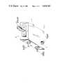
- FIG. 1is an isometric exterior view of a microwave dielectric resonator oscillator
- FIGS. 2 and 5are elevational views, partly in section, showing alternative interior structures for the oscillator exteriorly depicted in FIG. 1;
- FIGS. 3 and 4are elevational views, partly in section, illustrating modifications of the interior structures shown in FIGS. 2 and 5.
- FIGS. 1, 2 and 5the invention is illustrated as embodied in a microwave dielectric resonator oscillator 10 having a rectangular box-like housing 12 formed of a non-loss metal such as aluminum which confines the microwave fields.
- an adjusting screw 14 for use with a screwdriver in mechanically tuning oscillator 10is threaded within a small cylindrical sleeve 16 perpendicularly projecting from the bottom of housing 12.
- the back of housing 12carries an output jack connector 18 adapted for connection to a female fitting of a coaxial cable in order to couple the oscillator output from a hermetic feed-through terminal (not shown) to the coaxial cable in a conventional manner.
- a d.c. input terminal 20 and a ground terminal 22are mounted as hermetic feed-through terminals for respectively providing oscillator 10 with d.c. bias and reference potentials necessary for its operation.
- housing 12includes a hermetically sealed chamber 24 bounded at the top by a cover 26 which also serves as the top of housing 12.
- the bottom of hermetic chamber 24is provided by a substrate 28 of a suitable dielectric material transmissive to microwave fields and capable of forming a hermetic seal, such as alumina or quartz, parallel to cover 26.
- the bounds of hermetic chamber 24are completed by side portions of housing 12 to which the peripheries of cover 26 and substrate 28 are eventually soldered or brazed to provide chamber 24 with its hermetic integrity.
- Substrate 28supports on its upper surface a dielectric resonator puck 30 and microwave driving circuitry 32 along the puck and has on its opposite surface a metalizing film constituting a ground plane 34. A portion of the lower surface of substrate 28 underlies puck 30 and, being free of the metallizing film, provides substrates 28 with an r-f window 36 therethrough for microwave field lines developed around the resonating puck 30.
- a cup-shaped non-hermetic chamber 38is formed in housing 12 directly beneath window 36 for receiving the microwave field lines; and a circular metallic tuning slug 40 mounted at the inner end of adjusting screw 14 is disposed in non-hermetic chamber 38 to be selectively movable into different interfering relationships with the window transmitted field lines by mechanically turning the screw 14 in the internal threads of sleeve 16 and a continuation thereof in a housing hole extending the sleeve interior into non-hermetic chamber 38.
- Resonator puck 30is a precision ground cylinder of a suitable dielectric material, such as barium titanate, purified to an extremely high degree and having a dielectric constant in the range of said from 30 to 42.
- Microwave driving circuitry 32includes etched microstrip elements integrated with one or more negative resistance active elements, such as gallium arsenide field effect transistors (GaAsFETs), and is energized by applying a d.c. bias voltage thereto by way of hermetic feed-through terminal 20 (FIG. 1).
- GaAsFETsgallium arsenide field effect transistors
- the output of the driving circuitry 32feeding microwave energy to the puck to induce natural resonance which in turn feeds the input of the driving circuitry to stabilize the oscillator frequency.
- such fieldsrepresent the energy stored in the puck and the microwave field is a manifestation of that stored energy.
- part of that fieldpasses through window 36 to be influenced by the tuning slug 40 as a function of the positional relationship of the slug with the field part.
- the distribution and amount of the energy associated with the puck current and stored in the field about puck 30is altered, thereby effectively altering the resonant frequency of the puck without placing the mechanically movable tuning slug 40 in the hermetic chamber 24 enclosing the puck and its microwave driving circuitry 32.
- FIG. 5wherein like parts are identified by like reference numerals, the alternative interior structure for oscillator 10 (FIG. 1) is distinguished from the structure shown in FIG. 2 by the addition of a Kovar carrier 42 upon which electrical ground plane 34 uniformly rests and which has a cut-out coextensive with the window 36 of substrate 28.
- Kovar carrier 42facilitates the assembling of the apparatus, and lowers the thermally induced mechanical stress between the housing and the substrate.
- cup-shaped non-hermetic chamber 38is now formed in a cover assembly 44 of a modified housing 46; and a quartz or alumina window 48, transparent to microwave fields, hermetically seals the mouth of cup-shaped chamber 38 at its interface with hermetic chamber 24. Magnetic field lines about puck 30 accordingly pass upwardly through window 48 to be interfered with by tuning slug 40.
- puck-supporting substrate 28is now entirely metallized with a chrome-gold film to provide an uninterrupted electrical ground plane 50 for circuitry 32; and a Kovar carrier 52 sandwiched between the electrical ground plane and the bottom of housing 46 omits the circular cut-out required in carrier 42 of FIG. 5.
- a movable tuning slug 52is slid in a direction substantially parallel to the base of dielectric resonator puck 30 in order to achieve its different positional states of interference with the microwave field developed in and around puck 30.
- a modified housing 54has a base provided with a tapped horizontal hole 56 in which an adjusting screw 58 is threadedly engaged and which opens into a non-hermetic chamber 60 directly underlying window 36.
- a rod-shaped metallic tuning slug 62 of diameter less than that of hole 56is loosely connected to the inner end of adjusting screw 58 and rests on the floor of non-hermetic chamber 60 so that it will be slidably positioned into and out of non-hermetic chamber 60 in response to mechanical tuning of adjusting screw 58 by a screwdriver. Accordingly, the influence of tuning slug 62 on the part of the puck's surrounding microwave field transmitted out of hermetic chamber 24 through window 36 is a function of the positional relationship of the slug with that field part, as determined by the slug's sliding movements.
- 3)may be simplified by removing ceramic window (alumina, quartz, etc.) 48 and the fixed metal supporting portion thereof up to the supporting shoulder at the top of housing 46 and, by way of substitution, hermetically attaching the mouth of a ceramic cup to the underside of the remaining plate-like fixed metal portion so that the cup encloses tuning slug 40 with the bottom of the cup being disposed over the top of dielectric resonator puck 30.
- ceramic window (alumina, quartz, etc.) 48and the fixed metal supporting portion thereof up to the supporting shoulder at the top of housing 46 and, by way of substitution, hermetically attaching the mouth of a ceramic cup to the underside of the remaining plate-like fixed metal portion so that the cup encloses tuning slug 40 with the bottom of the cup being disposed over the top of dielectric resonator puck 30.
Landscapes
- Inductance-Capacitance Distribution Constants And Capacitance-Resistance Oscillators (AREA)
Abstract
Description
Claims (35)
Priority Applications (1)
| Application Number | Priority Date | Filing Date | Title |
|---|---|---|---|
| US06/548,924US4628283A (en) | 1983-11-07 | 1983-11-07 | Hermetically sealed oscillator with dielectric resonator tuned through dielectric window by adjusting screw |
Applications Claiming Priority (1)
| Application Number | Priority Date | Filing Date | Title |
|---|---|---|---|
| US06/548,924US4628283A (en) | 1983-11-07 | 1983-11-07 | Hermetically sealed oscillator with dielectric resonator tuned through dielectric window by adjusting screw |
Publications (1)
| Publication Number | Publication Date |
|---|---|
| US4628283Atrue US4628283A (en) | 1986-12-09 |
Family
ID=24190950
Family Applications (1)
| Application Number | Title | Priority Date | Filing Date |
|---|---|---|---|
| US06/548,924Expired - Fee RelatedUS4628283A (en) | 1983-11-07 | 1983-11-07 | Hermetically sealed oscillator with dielectric resonator tuned through dielectric window by adjusting screw |
Country Status (1)
| Country | Link |
|---|---|
| US (1) | US4628283A (en) |
Cited By (45)
| Publication number | Priority date | Publication date | Assignee | Title |
|---|---|---|---|---|
| US4733198A (en)* | 1986-10-06 | 1988-03-22 | Murata Erie North America, Inc. | Mechanically tunable sealed microwave oscillator |
| FR2614151A1 (en)* | 1987-04-15 | 1988-10-21 | Alcatel Thomson Faisceaux | HYPERFREQUENCY OSCILLATOR WITH DIELECTRIC RESONATOR, PARTICULARLY IN THE RANGE OF 22 GHZ |
| EP0306090A1 (en)* | 1987-09-04 | 1989-03-08 | Philips Composants | Microwave oscillator with a dielectric resonator stable against mechanical vibrations |
| EP0337371A3 (en)* | 1988-04-15 | 1990-03-14 | Siemens Aktiengesellschaft | Microwave oscillator |
| US5016072A (en)* | 1988-01-13 | 1991-05-14 | The Charles Stark Draper Laboratory, Inc. | Semiconductor chip gyroscopic transducer |
| US5105158A (en)* | 1990-02-13 | 1992-04-14 | Space Systems/Loral, Inc. | Dielectric microwave resonator probe |
| US5126812A (en)* | 1990-02-14 | 1992-06-30 | The Charles Stark Draper Laboratory, Inc. | Monolithic micromechanical accelerometer |
| US5129983A (en)* | 1991-02-25 | 1992-07-14 | The Charles Stark Draper Laboratory, Inc. | Method of fabrication of large area micromechanical devices |
| US5144184A (en)* | 1990-01-26 | 1992-09-01 | The Charles Stark Draper Laboratory, Inc. | Micromechanical device with a trimmable resonant frequency structure and method of trimming same |
| US5203208A (en)* | 1991-04-29 | 1993-04-20 | The Charles Stark Draper Laboratory | Symmetrical micromechanical gyroscope |
| US5216490A (en)* | 1988-01-13 | 1993-06-01 | Charles Stark Draper Laboratory, Inc. | Bridge electrodes for microelectromechanical devices |
| US5221913A (en)* | 1990-09-26 | 1993-06-22 | Matsushita Electric Industrial Co., Ltd. | Dielectric resonator device with thin plate type dielectric heat-radiator |
| US5262736A (en)* | 1991-03-23 | 1993-11-16 | Nec Corporation | Compact voltage controlled microwave oscillator with dielectric resonator |
| US5291153A (en)* | 1991-04-26 | 1994-03-01 | Sumitomo Electric Industries, Ltd. | Oscillating MMIC circuit with dielectric resonator |
| US5331852A (en)* | 1991-09-11 | 1994-07-26 | The Charles Stark Draper Laboratory, Inc. | Electromagnetic rebalanced micromechanical transducer |
| US5349855A (en)* | 1992-04-07 | 1994-09-27 | The Charles Stark Draper Laboratory, Inc. | Comb drive micromechanical tuning fork gyro |
| US5408877A (en)* | 1992-03-16 | 1995-04-25 | The Charles Stark Draper Laboratory, Inc. | Micromechanical gyroscopic transducer with improved drive and sense capabilities |
| US5507911A (en)* | 1990-10-17 | 1996-04-16 | The Charles Stark Draper Laboratory, Inc. | Monolithic micromechanical vibrating string accelerometer with trimmable resonant frequency |
| US5581035A (en)* | 1994-08-29 | 1996-12-03 | The Charles Stark Draper Laboratory, Inc. | Micromechanical sensor with a guard band electrode |
| US5605598A (en)* | 1990-10-17 | 1997-02-25 | The Charles Stark Draper Laboratory Inc. | Monolithic micromechanical vibrating beam accelerometer with trimmable resonant frequency |
| US5635639A (en)* | 1991-09-11 | 1997-06-03 | The Charles Stark Draper Laboratory, Inc. | Micromechanical tuning fork angular rate sensor |
| US5635739A (en)* | 1990-02-14 | 1997-06-03 | The Charles Stark Draper Laboratory, Inc. | Micromechanical angular accelerometer with auxiliary linear accelerometer |
| US5646348A (en)* | 1994-08-29 | 1997-07-08 | The Charles Stark Draper Laboratory, Inc. | Micromechanical sensor with a guard band electrode and fabrication technique therefor |
| US5650568A (en)* | 1993-02-10 | 1997-07-22 | The Charles Stark Draper Laboratory, Inc. | Gimballed vibrating wheel gyroscope having strain relief features |
| US5666093A (en)* | 1995-08-11 | 1997-09-09 | D'ostilio; James Phillip | Mechanically tunable ceramic bandpass filter having moveable tabs |
| US5725729A (en)* | 1994-09-26 | 1998-03-10 | The Charles Stark Draper Laboratory, Inc. | Process for micromechanical fabrication |
| US5767405A (en)* | 1992-04-07 | 1998-06-16 | The Charles Stark Draper Laboratory, Inc. | Comb-drive micromechanical tuning fork gyroscope with piezoelectric readout |
| US5783973A (en)* | 1997-02-24 | 1998-07-21 | The Charles Stark Draper Laboratory, Inc. | Temperature insensitive silicon oscillator and precision voltage reference formed therefrom |
| WO1998028813A3 (en)* | 1996-12-20 | 1998-09-11 | Ericsson Telefon Ab L M | Fixed tuneable loop |
| US5817942A (en)* | 1996-02-28 | 1998-10-06 | The Charles Stark Draper Laboratory, Inc. | Capacitive in-plane accelerometer |
| US5834993A (en)* | 1996-08-20 | 1998-11-10 | Hughes Electronics Corporation | Passive microwave structure and methods having reduced passive intermodulation |
| US5892153A (en)* | 1996-11-21 | 1999-04-06 | The Charles Stark Draper Laboratory, Inc. | Guard bands which control out-of-plane sensitivities in tuning fork gyroscopes and other sensors |
| US5911156A (en)* | 1997-02-24 | 1999-06-08 | The Charles Stark Draper Laboratory, Inc. | Split electrode to minimize charge transients, motor amplitude mismatch errors, and sensitivity to vertical translation in tuning fork gyros and other devices |
| US5952574A (en)* | 1997-04-29 | 1999-09-14 | The Charles Stark Draper Laboratory, Inc. | Trenches to reduce charging effects and to control out-of-plane sensitivities in tuning fork gyroscopes and other sensors |
| US5986208A (en)* | 1996-03-19 | 1999-11-16 | Pacific Coast Technologies, Inc. | Waveguide window assembly and microwave electronics package |
| EP0959565A1 (en)* | 1998-05-22 | 1999-11-24 | Murata Manufacturing Co., Ltd. | Oscillator and communications device |
| FR2785141A1 (en)* | 1998-10-27 | 2000-04-28 | Electrovac | Metal casing for electrical or electronic circuits includes aperture for HF communication to waveguide, with hermetic seal |
| US6384699B1 (en)* | 1999-04-14 | 2002-05-07 | Telefonaktiebolaget Lm Ericsson (Publ) | Tuning arrangement for a cavity filter |
| US7227434B2 (en)* | 2000-07-14 | 2007-06-05 | Allgon Ab | Tuning screw assembly |
| US20080285617A1 (en)* | 2007-05-08 | 2008-11-20 | Moldover Michael R | Dielectric resonator thermometer and a method of using the same |
| US8187902B2 (en) | 2008-07-09 | 2012-05-29 | The Charles Stark Draper Laboratory, Inc. | High performance sensors and methods for forming the same |
| CN101922493B (en)* | 2009-06-11 | 2012-10-17 | 深圳市大富科技股份有限公司 | Screw device and cavity filter using same |
| US20140262040A1 (en)* | 2013-03-15 | 2014-09-18 | Tokyo Electron Limited | Method and system using plasma tuning rods for plasma processing |
| US9212053B2 (en)* | 2013-01-09 | 2015-12-15 | Stmicroelectronics (Rousset) Sas | Process for producing a metal device housed in a closed housing within an integrated circuit, and corresponding integrated circuit |
| US20230215595A1 (en)* | 2020-05-12 | 2023-07-06 | Eaton Intelligent Power Limited | Grounding element and electrical installation component having a grounding element |
Citations (11)
| Publication number | Priority date | Publication date | Assignee | Title |
|---|---|---|---|---|
| US3158825A (en)* | 1962-05-10 | 1964-11-24 | Maurice J Vetter | Movable resonant cavity tuning probe in dielectric sleeve having nonuniform outer surface |
| US3390300A (en)* | 1965-10-22 | 1968-06-25 | Varian Associates | High frequency electron discharge devices of the klystron type incorporating below cut-off waveguide leaky wall h-field tuners |
| US3421122A (en)* | 1965-09-30 | 1969-01-07 | Fujitsu Ltd | Miniature adjustable high frequency resonant circuit unit |
| US3596204A (en)* | 1969-07-02 | 1971-07-27 | Varian Associates | Tunable coaxial cavity semiconductor negative resistance oscillator |
| US3701049A (en)* | 1969-10-25 | 1972-10-24 | Philips Corp | Microwave oscillator employing a cavity resonator having dielectric walls used as a quarter wave impedance transformer |
| SU409319A1 (en)* | 1972-07-18 | 1973-11-30 | RESONATOR SETTINGS ELEMENT12 | |
| DE2336810A1 (en)* | 1972-07-24 | 1974-02-14 | Siemens Ag Albis | CYLINDRICAL CAVITY RESONATOR |
| DE2538614A1 (en)* | 1974-09-06 | 1976-03-18 | Murata Manufacturing Co | DIELECTRIC RESONATOR |
| JPS5227293A (en)* | 1975-08-26 | 1977-03-01 | Seikosha Co Ltd | Air-tight sealing method of crystal oscillator |
| JPS5233450A (en)* | 1975-09-10 | 1977-03-14 | Hitachi Ltd | Microwave integrated circuit unit |
| JPS5412553A (en)* | 1977-06-29 | 1979-01-30 | Toshiba Corp | Microwave oscillation circuit |
- 1983
- 1983-11-07USUS06/548,924patent/US4628283A/ennot_activeExpired - Fee Related
Patent Citations (11)
| Publication number | Priority date | Publication date | Assignee | Title |
|---|---|---|---|---|
| US3158825A (en)* | 1962-05-10 | 1964-11-24 | Maurice J Vetter | Movable resonant cavity tuning probe in dielectric sleeve having nonuniform outer surface |
| US3421122A (en)* | 1965-09-30 | 1969-01-07 | Fujitsu Ltd | Miniature adjustable high frequency resonant circuit unit |
| US3390300A (en)* | 1965-10-22 | 1968-06-25 | Varian Associates | High frequency electron discharge devices of the klystron type incorporating below cut-off waveguide leaky wall h-field tuners |
| US3596204A (en)* | 1969-07-02 | 1971-07-27 | Varian Associates | Tunable coaxial cavity semiconductor negative resistance oscillator |
| US3701049A (en)* | 1969-10-25 | 1972-10-24 | Philips Corp | Microwave oscillator employing a cavity resonator having dielectric walls used as a quarter wave impedance transformer |
| SU409319A1 (en)* | 1972-07-18 | 1973-11-30 | RESONATOR SETTINGS ELEMENT12 | |
| DE2336810A1 (en)* | 1972-07-24 | 1974-02-14 | Siemens Ag Albis | CYLINDRICAL CAVITY RESONATOR |
| DE2538614A1 (en)* | 1974-09-06 | 1976-03-18 | Murata Manufacturing Co | DIELECTRIC RESONATOR |
| JPS5227293A (en)* | 1975-08-26 | 1977-03-01 | Seikosha Co Ltd | Air-tight sealing method of crystal oscillator |
| JPS5233450A (en)* | 1975-09-10 | 1977-03-14 | Hitachi Ltd | Microwave integrated circuit unit |
| JPS5412553A (en)* | 1977-06-29 | 1979-01-30 | Toshiba Corp | Microwave oscillation circuit |
Non-Patent Citations (6)
| Title |
|---|
| A. Jacob et al., "Broad Band Tunable GaAs-FET Oscillator With Hybrid Coupled Microstrip and Evanescent-Mode Resonators", Proceedings of the 10th European Microwave Conference Warsaw, Poland, Sep. 8-12, 1980, pp. 709-713. |
| A. Jacob et al., Broad Band Tunable GaAs FET Oscillator With Hybrid Coupled Microstrip and Evanescent Mode Resonators , Proceedings of the 10th European Microwave Conference Warsaw, Poland, Sep. 8 12, 1980, pp. 709 713.* |
| H. Nagao et al., "A Millimeter-Wave IMPATT Diode Hermetically Sealed in a Miniature Ceramic Package", NEC Research & Development No. 52, Jan. 79, pp. 33-38. |
| H. Nagao et al., A Millimeter Wave IMPATT Diode Hermetically Sealed in a Miniature Ceramic Package , NEC Research & Development No. 52, Jan. 79, pp. 33 38.* |
| R. Knochel et al., "Temperature Compensation of Cavity Stabilized Gunn Oscillators", Electronics Letters vol. 13, No. 24, Nov. 24, 1977, pp. 723-724. |
| R. Knochel et al., Temperature Compensation of Cavity Stabilized Gunn Oscillators , Electronics Letters vol. 13, No. 24, Nov. 24, 1977, pp. 723 724.* |
Cited By (60)
| Publication number | Priority date | Publication date | Assignee | Title |
|---|---|---|---|---|
| US4733198A (en)* | 1986-10-06 | 1988-03-22 | Murata Erie North America, Inc. | Mechanically tunable sealed microwave oscillator |
| US4862111A (en)* | 1987-04-15 | 1989-08-29 | Societe Anonyme Dite Alcatel Thomson Faisceaux Hertziens | Microwave oscillator having a dielectric resonator, in particular for the 22 GHz range |
| FR2614151A1 (en)* | 1987-04-15 | 1988-10-21 | Alcatel Thomson Faisceaux | HYPERFREQUENCY OSCILLATOR WITH DIELECTRIC RESONATOR, PARTICULARLY IN THE RANGE OF 22 GHZ |
| EP0290794A1 (en)* | 1987-04-15 | 1988-11-17 | Alcatel Telspace | Microwave oscillator with a dielectric resonator, especially for the 22 GHz range |
| US4873495A (en)* | 1987-09-04 | 1989-10-10 | U.S. Philips Corporation | Ultrahigh-frequency oscillator having a dielectric resonator stable with respect to mechanical vibrations |
| FR2620281A1 (en)* | 1987-09-04 | 1989-03-10 | Radiotechnique Compelec | HYPERFREQUENCE OSCILLATOR WITH DIELECTRIC RESONATOR, STABLE IN RELATION TO MECHANICAL VIBRATION |
| EP0306090A1 (en)* | 1987-09-04 | 1989-03-08 | Philips Composants | Microwave oscillator with a dielectric resonator stable against mechanical vibrations |
| US5016072A (en)* | 1988-01-13 | 1991-05-14 | The Charles Stark Draper Laboratory, Inc. | Semiconductor chip gyroscopic transducer |
| US5216490A (en)* | 1988-01-13 | 1993-06-01 | Charles Stark Draper Laboratory, Inc. | Bridge electrodes for microelectromechanical devices |
| EP0337371A3 (en)* | 1988-04-15 | 1990-03-14 | Siemens Aktiengesellschaft | Microwave oscillator |
| US4922211A (en)* | 1988-04-15 | 1990-05-01 | Siemens Aktiengesellschaft | Microwave oscillator in which the dielectric resonator is hermetically sealed |
| US5144184A (en)* | 1990-01-26 | 1992-09-01 | The Charles Stark Draper Laboratory, Inc. | Micromechanical device with a trimmable resonant frequency structure and method of trimming same |
| US5105158A (en)* | 1990-02-13 | 1992-04-14 | Space Systems/Loral, Inc. | Dielectric microwave resonator probe |
| US5126812A (en)* | 1990-02-14 | 1992-06-30 | The Charles Stark Draper Laboratory, Inc. | Monolithic micromechanical accelerometer |
| US5635739A (en)* | 1990-02-14 | 1997-06-03 | The Charles Stark Draper Laboratory, Inc. | Micromechanical angular accelerometer with auxiliary linear accelerometer |
| WO1991014285A1 (en)* | 1990-03-14 | 1991-09-19 | The Charles Stark Draper Laboratory, Inc. | Semiconductor chip gyroscopic transducer |
| US5221913A (en)* | 1990-09-26 | 1993-06-22 | Matsushita Electric Industrial Co., Ltd. | Dielectric resonator device with thin plate type dielectric heat-radiator |
| US5507911A (en)* | 1990-10-17 | 1996-04-16 | The Charles Stark Draper Laboratory, Inc. | Monolithic micromechanical vibrating string accelerometer with trimmable resonant frequency |
| US5969250A (en)* | 1990-10-17 | 1999-10-19 | The Charles Stark Draper Laboratory, Inc. | Micromechanical accelerometer having a peripherally suspended proof mass |
| US5760305A (en)* | 1990-10-17 | 1998-06-02 | The Charles Stark Draper Laboratory, Inc. | Monolithic micromechanical vibrating beam accelerometer with trimmable resonant frequency |
| US5605598A (en)* | 1990-10-17 | 1997-02-25 | The Charles Stark Draper Laboratory Inc. | Monolithic micromechanical vibrating beam accelerometer with trimmable resonant frequency |
| US5129983A (en)* | 1991-02-25 | 1992-07-14 | The Charles Stark Draper Laboratory, Inc. | Method of fabrication of large area micromechanical devices |
| US5262736A (en)* | 1991-03-23 | 1993-11-16 | Nec Corporation | Compact voltage controlled microwave oscillator with dielectric resonator |
| US5291153A (en)* | 1991-04-26 | 1994-03-01 | Sumitomo Electric Industries, Ltd. | Oscillating MMIC circuit with dielectric resonator |
| US5203208A (en)* | 1991-04-29 | 1993-04-20 | The Charles Stark Draper Laboratory | Symmetrical micromechanical gyroscope |
| US5635639A (en)* | 1991-09-11 | 1997-06-03 | The Charles Stark Draper Laboratory, Inc. | Micromechanical tuning fork angular rate sensor |
| US5505084A (en)* | 1991-09-11 | 1996-04-09 | The Charles Stark Draper Laboratory, Inc. | Micromechanical tuning fork angular rate sensor |
| US5331852A (en)* | 1991-09-11 | 1994-07-26 | The Charles Stark Draper Laboratory, Inc. | Electromagnetic rebalanced micromechanical transducer |
| US5408877A (en)* | 1992-03-16 | 1995-04-25 | The Charles Stark Draper Laboratory, Inc. | Micromechanical gyroscopic transducer with improved drive and sense capabilities |
| US5515724A (en)* | 1992-03-16 | 1996-05-14 | The Charles Stark Draper Laboratory, Inc. | Micromechanical gyroscopic transducer with improved drive and sense capabilities |
| US5767405A (en)* | 1992-04-07 | 1998-06-16 | The Charles Stark Draper Laboratory, Inc. | Comb-drive micromechanical tuning fork gyroscope with piezoelectric readout |
| US5496436A (en)* | 1992-04-07 | 1996-03-05 | The Charles Stark Draper Laboratory, Inc. | Comb drive micromechanical tuning fork gyro fabrication method |
| US5349855A (en)* | 1992-04-07 | 1994-09-27 | The Charles Stark Draper Laboratory, Inc. | Comb drive micromechanical tuning fork gyro |
| US5650568A (en)* | 1993-02-10 | 1997-07-22 | The Charles Stark Draper Laboratory, Inc. | Gimballed vibrating wheel gyroscope having strain relief features |
| US5581035A (en)* | 1994-08-29 | 1996-12-03 | The Charles Stark Draper Laboratory, Inc. | Micromechanical sensor with a guard band electrode |
| US5646348A (en)* | 1994-08-29 | 1997-07-08 | The Charles Stark Draper Laboratory, Inc. | Micromechanical sensor with a guard band electrode and fabrication technique therefor |
| US5725729A (en)* | 1994-09-26 | 1998-03-10 | The Charles Stark Draper Laboratory, Inc. | Process for micromechanical fabrication |
| US5666093A (en)* | 1995-08-11 | 1997-09-09 | D'ostilio; James Phillip | Mechanically tunable ceramic bandpass filter having moveable tabs |
| US5817942A (en)* | 1996-02-28 | 1998-10-06 | The Charles Stark Draper Laboratory, Inc. | Capacitive in-plane accelerometer |
| US5986208A (en)* | 1996-03-19 | 1999-11-16 | Pacific Coast Technologies, Inc. | Waveguide window assembly and microwave electronics package |
| US6044538A (en)* | 1996-08-20 | 2000-04-04 | Hughes Electronics Corporation | Passive microwave structures and methods having reduced passive intermodulation |
| US5834993A (en)* | 1996-08-20 | 1998-11-10 | Hughes Electronics Corporation | Passive microwave structure and methods having reduced passive intermodulation |
| US5892153A (en)* | 1996-11-21 | 1999-04-06 | The Charles Stark Draper Laboratory, Inc. | Guard bands which control out-of-plane sensitivities in tuning fork gyroscopes and other sensors |
| WO1998028813A3 (en)* | 1996-12-20 | 1998-09-11 | Ericsson Telefon Ab L M | Fixed tuneable loop |
| US6005452A (en)* | 1996-12-20 | 1999-12-21 | Telefonaktiebolget Lm Ericsson | Fixed tuneable loop |
| US5911156A (en)* | 1997-02-24 | 1999-06-08 | The Charles Stark Draper Laboratory, Inc. | Split electrode to minimize charge transients, motor amplitude mismatch errors, and sensitivity to vertical translation in tuning fork gyros and other devices |
| US5783973A (en)* | 1997-02-24 | 1998-07-21 | The Charles Stark Draper Laboratory, Inc. | Temperature insensitive silicon oscillator and precision voltage reference formed therefrom |
| US5952574A (en)* | 1997-04-29 | 1999-09-14 | The Charles Stark Draper Laboratory, Inc. | Trenches to reduce charging effects and to control out-of-plane sensitivities in tuning fork gyroscopes and other sensors |
| EP0959565A1 (en)* | 1998-05-22 | 1999-11-24 | Murata Manufacturing Co., Ltd. | Oscillator and communications device |
| US6236279B1 (en) | 1998-05-22 | 2001-05-22 | Murata Manufacturing Co., Ltd. | Oscillator and communications device |
| FR2785141A1 (en)* | 1998-10-27 | 2000-04-28 | Electrovac | Metal casing for electrical or electronic circuits includes aperture for HF communication to waveguide, with hermetic seal |
| US6384699B1 (en)* | 1999-04-14 | 2002-05-07 | Telefonaktiebolaget Lm Ericsson (Publ) | Tuning arrangement for a cavity filter |
| US7227434B2 (en)* | 2000-07-14 | 2007-06-05 | Allgon Ab | Tuning screw assembly |
| US20080285617A1 (en)* | 2007-05-08 | 2008-11-20 | Moldover Michael R | Dielectric resonator thermometer and a method of using the same |
| US8123399B2 (en)* | 2007-05-08 | 2012-02-28 | The United States of America as represented by the National Institute of Standards and Technology | Dielectric resonator thermometer and a method of using the same |
| US8187902B2 (en) | 2008-07-09 | 2012-05-29 | The Charles Stark Draper Laboratory, Inc. | High performance sensors and methods for forming the same |
| CN101922493B (en)* | 2009-06-11 | 2012-10-17 | 深圳市大富科技股份有限公司 | Screw device and cavity filter using same |
| US9212053B2 (en)* | 2013-01-09 | 2015-12-15 | Stmicroelectronics (Rousset) Sas | Process for producing a metal device housed in a closed housing within an integrated circuit, and corresponding integrated circuit |
| US20140262040A1 (en)* | 2013-03-15 | 2014-09-18 | Tokyo Electron Limited | Method and system using plasma tuning rods for plasma processing |
| US20230215595A1 (en)* | 2020-05-12 | 2023-07-06 | Eaton Intelligent Power Limited | Grounding element and electrical installation component having a grounding element |
Similar Documents
| Publication | Publication Date | Title |
|---|---|---|
| US4628283A (en) | Hermetically sealed oscillator with dielectric resonator tuned through dielectric window by adjusting screw | |
| US4639690A (en) | Tunable, dielectric-resonator-stabilized oscillator and method of tuning same | |
| US4609883A (en) | Microwave oscillator hermetically sealed and coupled to dielectric resonator | |
| US4521746A (en) | Microwave oscillator with TM01δ dielectric resonator | |
| US4477788A (en) | Dielectric resonator tuner and mechanical mounting system | |
| US4871983A (en) | Electronically tuned dielectric resonator stabilized oscillator | |
| EP0121824B1 (en) | Microwave oscillator | |
| US4588964A (en) | Hermetically sealed microwave solid-state oscillator with dielectric resonator tuned by electromagnetically coupled terminating admittance | |
| CA1115361A (en) | Microwave oscillator for microwave integrated circuit applications | |
| EP0959557B1 (en) | Oscillator and communications device | |
| US3996529A (en) | Varactor tuning apparatus for a strip transmission line device | |
| US3739298A (en) | Broad band tunable solid state microwave oscillator | |
| JPS6141441B2 (en) | ||
| US5428326A (en) | Fast turn-on, temperature stable dielectric resonator oscillator | |
| US4766398A (en) | Broadband temperature compensated microwave cavity oscillator | |
| US4847571A (en) | Microwave oscillator integrated in a waveguide | |
| JPH04294616A (en) | Voltage controlled oscillator | |
| US3693118A (en) | Variable tuning arrangement for a strip transmission line circuit | |
| US4873495A (en) | Ultrahigh-frequency oscillator having a dielectric resonator stable with respect to mechanical vibrations | |
| US6172577B1 (en) | Oscillator and oscillation apparatus using the oscillator | |
| SU1709493A1 (en) | Shf oscillator stabilized by dielectric resonator | |
| JPS61265906A (en) | Microwave oscillation circuit | |
| JPS59163840A (en) | Vessel for semiconductor element | |
| JPH05304386A (en) | Housing for high frequency circuit | |
| JP2000138495A (en) | Package of high-frequency integrated circuit |
Legal Events
| Date | Code | Title | Description |
|---|---|---|---|
| AS | Assignment | Owner name:NARDA MICROWAVE CORPORATION, THE 435 MORELAND ROAD Free format text:ASSIGNMENT OF ASSIGNORS INTEREST.;ASSIGNOR:REYNOLDS, ALLAN;REEL/FRAME:004199/0512 Effective date:19831207 Owner name:NARDA MICROWAVE CORPORATION, THE 435 MORELAND ROAD Free format text:ASSIGNMENT OF ASSIGNORS INTEREST;ASSIGNOR:REYNOLDS, ALLAN;REEL/FRAME:004199/0512 Effective date:19831207 | |
| FEPP | Fee payment procedure | Free format text:PAYOR NUMBER ASSIGNED (ORIGINAL EVENT CODE: ASPN); ENTITY STATUS OF PATENT OWNER: LARGE ENTITY | |
| FPAY | Fee payment | Year of fee payment:4 | |
| FPAY | Fee payment | Year of fee payment:8 | |
| AS | Assignment | Owner name:LOCKHEED MARTIN CORP., MARYLAND Free format text:ASSIGNMENT OF ASSIGNORS INTEREST;ASSIGNOR:NARDA MICROWAVE CORP.;REEL/FRAME:008800/0887 Effective date:19971113 | |
| REMI | Maintenance fee reminder mailed | ||
| LAPS | Lapse for failure to pay maintenance fees | ||
| FP | Lapsed due to failure to pay maintenance fee | Effective date:19981209 | |
| AS | Assignment | Owner name:L-3 COMMUNICATIONS CORPORATION, NEW YORK Free format text:ASSIGNMENT OF ASSIGNORS INTEREST;ASSIGNOR:LOCKHEED MARTIN CORPORATION, A CORP. OF MD;REEL/FRAME:010180/0073 Effective date:19970430 | |
| STCH | Information on status: patent discontinuation | Free format text:PATENT EXPIRED DUE TO NONPAYMENT OF MAINTENANCE FEES UNDER 37 CFR 1.362 |