US4626967A - Auxiliary lamp arrangement for automotive vehicle or the like - Google Patents
Auxiliary lamp arrangement for automotive vehicle or the likeDownload PDFInfo
- Publication number
- US4626967A US4626967AUS06/711,323US71132385AUS4626967AUS 4626967 AUS4626967 AUS 4626967AUS 71132385 AUS71132385 AUS 71132385AUS 4626967 AUS4626967 AUS 4626967A
- Authority
- US
- United States
- Prior art keywords
- opening
- upper section
- light source
- lamp arrangement
- windshield
- Prior art date
- Legal status (The legal status is an assumption and is not a legal conclusion. Google has not performed a legal analysis and makes no representation as to the accuracy of the status listed.)
- Expired - Lifetime
Links
Images


Classifications
- B—PERFORMING OPERATIONS; TRANSPORTING
- B60—VEHICLES IN GENERAL
- B60Q—ARRANGEMENT OF SIGNALLING OR LIGHTING DEVICES, THE MOUNTING OR SUPPORTING THEREOF OR CIRCUITS THEREFOR, FOR VEHICLES IN GENERAL
- B60Q1/00—Arrangement of optical signalling or lighting devices, the mounting or supporting thereof or circuits therefor
- B60Q1/26—Arrangement of optical signalling or lighting devices, the mounting or supporting thereof or circuits therefor the devices being primarily intended to indicate the vehicle, or parts thereof, or to give signals, to other traffic
- B60Q1/30—Arrangement of optical signalling or lighting devices, the mounting or supporting thereof or circuits therefor the devices being primarily intended to indicate the vehicle, or parts thereof, or to give signals, to other traffic for indicating rear of vehicle, e.g. by means of reflecting surfaces
- B60Q1/302—Arrangement of optical signalling or lighting devices, the mounting or supporting thereof or circuits therefor the devices being primarily intended to indicate the vehicle, or parts thereof, or to give signals, to other traffic for indicating rear of vehicle, e.g. by means of reflecting surfaces mounted in the vicinity, e.g. in the middle, of a rear window
Definitions
- the present inventionrelates generally to lamp arrangements for use in vehicles and more specifically to an improved lamp arrangement which can be disposed immediately adjacent the rear windshield or on the top of a trunk lid and which features a low profile which renders disposition of the lamp arrangement in the afore mentioned positions possible without imparing rear vision.
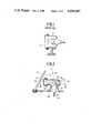
- FIG. 1shows a similar arrangement wherein an incandescent bulb 1 is disposed in a housing 2.
- the front of the housing 2is closed by a transparent or light transmissive cover 3.
- the sizeviz., the vertical dimensions
- the inner dimensions of the housing 2cannot be reduced beyond the diameter "D" of the bulb.
- some clearancemust be provided between the bulb and the inner walls of the housing 2 so as to prevent excessive localized heating thereof by the heat radiation given off by the bulb and further to allow for the bulb to be readily inserted and removed.
- a light bulbis arranged in an essentially vertically extending base section of a housing so that the filament thereof is located at a level just above that of the floor of an elongate capsule-like upper section provided on top of the base member.
- the filamentis arranged parallel with a lens or similar light transmissive member which is disposed in an opening formed in the upper section.
- the present inventiontakes the form of a vehicle lamp arrangement which comprises: a housing which is arranged to be mounted on a portion of the vehicle and which is formed with an opening, the opening having a shadow which is cast into the housing; and a light source disposed within the housing so that the light generating portion of the light source is located in said shadow proximate the lower periphery of the shadow.
- FIG. 1shows the second of the two prior art arrangements discussed in the introductory paragraphs of the present invention
- FIG. 2shows in sectional elevation a first embodiment of the present invention
- FIG. 3shows a sectional view taken along section line III--III of FIG. 2;
- FIG. 4is a perspective view of the arrangement shown in FIGS. 2 and 3;
- FIG. 5is a perspective view showing the arrangement shown in FIGS. 2-4 disposed on the parcel shelf of a sedan type automotive vehicle;
- FIG. 6is a sectional elevation similar to FIG. 2 showing the light reflection which occurs when the bulb disposed therein is energized;
- FIG. 7is a sectional elevation showing a second embodiment of the present invention.
- FIG. 8is a perspective view of a sedan vehicle wherein the second embodiment is mounted on the trunk lid thereof;
- FIGS. 9 and 10are sectional side and front elevations respectively of a third embodiment of the present invention.
- FIGS. 2 to 6 of the drawingsA first embodiment of the present invention is shown in FIGS. 2 to 6 of the drawings.
- the lamp arrangement 10is mounted on the rear parcel shelf 11 so as to be located immediately adjacent the rear windshield 12 of an automotive vehicle.
- the housing of the lamp devicecomprises a base portion or member 14 which is secured to the parcel shelf 11 and a capsule-like upper section 16 which is elongate in the horizontal direction.
- the upper section 16is formed with an opening 18 at one end. This opening 18 is closed by a light transmissive lens member 20.
- the lens member 20is secured to the upper section 20 by a grommet-like packing member or seal 21 which prevents the entry of the dust particles and the like into the interior of the housing.
- An incandescent bulb 22is supported in the base portion 14 of the housing by a socket 24.
- This socket 24can be detachably connected to the inner wall structure of the base member so as to facilitate ready assembly and/or repair.
- the base of the socket 24 and the lead wires 26which establish electrical connection between a brake pedal switch and source of EMF (not shown), extend down through an aperture 28 formed in the parcel shelf 11.
- the base member 14is secured to the shelf so as to conceal the aperture.
- the socket 24is arranged to support the incandescent bulb 22 in a manner that the filament 30 thereof is essentially flush with the lower inner wall or floor 32 of the capsule-like upper section 16. Viz., the filament 30 is arranged to project slightly into the shadow "S" which is defined by projection of the opening 18 back into the housing and thus be located in the shadow near the lower periphery thereof.
- the rear end wall 34 of the upper section 16, viz., the end opposite opening 18,is curved (see FIGS. 3 and 6) and preferably provided with a reflective surface 36 so that when the bulb 22 is energized in response to depression of the brake pedal (or alternatively operation of turn indicator control lever) the light rays produced by the bulb 22 are reflected from the rear end wall 34 essentially as illustrated in FIGS. 3 and 6.
- FIGS. 7 and 8show second embodiment of the present invention.
- This embodimentis designed to be mounted on top of the trunk lid of the vehicle.
- an air scoop-like cowl member 40is provided on the trunk lid 42.
- a lamp housing 44which is essentially similar in shape and construction to that used in the first embodiment, is disposed within the cavity 46 defined between the cowl member 40 and the upper surface of the trunk lid 42.
- the base portion 47 of the housingis arranged to project down through an aperture 48 formed in the trunk lid.
- the socket 49is detachably secured to the base portion of the housing so that simply by opening the trunk lid 42 the bulb 22 may be readily exchanged in the event of filament failure or the like.
- annular seal 50 or packingis disposed about the aperture 48 as shown, and arranged to seal the gap defined between the lower surface of capsule-like section of the housing and the top of the trunk lid.
- FIGS. 9 and 10show a third embodiment of the present invention.
- This embodimentresembles that shown in FIGS. 2 to 6, however further features inner and outer lenses 60, 62, a detachable cover 64 for facilitating easy bulb replacement, a reflector 66 secured to the roof of the capsule-like section and an arrangement which prevents light emitted by the bulb 22 from being reflected off the rear windshield 12 and causing undesirable view impairing images thereon.
- the latter mentioned arrangementtakes the form of an essentially rectangular member 68 which establishes contact with the inner surface of the rear windshield 12 and the outer periphery of the capsule-like upper member.
- the housingmay be suitably grooved as shown, to facilitate connecting the member 68 thereto.
- the provision of the reflector 66 in a spaced relationship with the inner surface of the upper sectionprovides an air space which thermally insulates the roof of the upper section preventing any localized heating thereof.
- the filament 30 of the bulb 22is arranged to be essentially parallel (see FIG. 3) with the lens or lenses of the lamp arrangement in which it is disposed.
Landscapes
- Engineering & Computer Science (AREA)
- Mechanical Engineering (AREA)
- Lighting Device Outwards From Vehicle And Optical Signal (AREA)
Abstract
Description
Claims (16)
Applications Claiming Priority (2)
| Application Number | Priority Date | Filing Date | Title |
|---|---|---|---|
| JP59-49777 | 1984-03-15 | ||
| JP59049777AJPS60193738A (en) | 1984-03-15 | 1984-03-15 | Lighting device for vehicle |
Publications (1)
| Publication Number | Publication Date |
|---|---|
| US4626967Atrue US4626967A (en) | 1986-12-02 |
Family
ID=12840598
Family Applications (1)
| Application Number | Title | Priority Date | Filing Date |
|---|---|---|---|
| US06/711,323Expired - LifetimeUS4626967A (en) | 1984-03-15 | 1985-03-13 | Auxiliary lamp arrangement for automotive vehicle or the like |
Country Status (2)
| Country | Link |
|---|---|
| US (1) | US4626967A (en) |
| JP (1) | JPS60193738A (en) |
Cited By (29)
| Publication number | Priority date | Publication date | Assignee | Title |
|---|---|---|---|---|
| US4724515A (en)* | 1985-04-26 | 1988-02-09 | Nissan Motor Co., Ltd. | Vehicle-use lamp fixture and braking indicator mechanism |
| US4736279A (en)* | 1985-03-14 | 1988-04-05 | Toyota Motor Corporation | Vehicle lamp device to be mounted on a spoiler |
| US4791534A (en)* | 1987-08-07 | 1988-12-13 | Lindberg Victor L | Vehicle including substantially transparent high mounted stop light |
| US4800471A (en)* | 1988-08-10 | 1989-01-24 | Lippert Raymond E | Brake light attachment |
| US4831501A (en)* | 1987-10-23 | 1989-05-16 | Koito Seisakusho Co., Ltd. | Reduced temperature lamp assembly suitable for use as a supplemental high mounted stop lamp on a motor vehicle |
| USD304504S (en) | 1986-05-28 | 1989-11-07 | Cheng Pin Chen | Auxiliary automotive vehicle brake light |
| US4893220A (en)* | 1987-12-28 | 1990-01-09 | Koito Manufacturing Co., Ltd. | High-mounted stoplight for motor vehicle |
| US4896251A (en)* | 1988-12-06 | 1990-01-23 | Fasel Albert J | Auxiliary turn signal attachment |
| US4916592A (en)* | 1989-08-17 | 1990-04-10 | General Motors Corporation | Center high mounted stoplight |
| US4945456A (en)* | 1987-12-28 | 1990-07-31 | Koito Manufacturing Co., Ltd. | High-mounted stoplight for motor vehicle |
| USD313661S (en) | 1987-04-03 | 1991-01-08 | Kang Weui Y | Combined auxiliary vehicle brake signal light and turn signal |
| USD334820S (en) | 1988-04-15 | 1993-04-13 | Lee Kyung C | Auxilary vehicle emergency light |
| US5207492A (en)* | 1990-02-20 | 1993-05-04 | K. W. Muth Company, Inc. | Mirror assembly |
| USD336145S (en) | 1991-03-14 | 1993-06-01 | Reifslager Michael D | Auxiliary flashing tail light for towed equipment |
| US5355284A (en)* | 1990-02-20 | 1994-10-11 | K. W. Muth Company, Inc. | Mirror assembly |
| US5361190A (en)* | 1990-02-20 | 1994-11-01 | K. W. Muth Co. Inc. | Mirror assembly |
| US5481409A (en)* | 1990-02-20 | 1996-01-02 | K. W. Muth Company, Inc. | Mirror assembly |
| US5671996A (en)* | 1994-12-30 | 1997-09-30 | Donnelly Corporation | Vehicle instrumentation/console lighting |
| US5788357A (en)* | 1996-08-28 | 1998-08-04 | K. W. Muth Company, Inc. | Mirror assembly |
| US6005724A (en)* | 1998-10-05 | 1999-12-21 | K. W. Muth Company, Inc. | Mirror coating, mirror utilizing same, and a mirror assembly |
| US6045243A (en)* | 1996-08-28 | 2000-04-04 | K.W. Muth Company, Inc. | Mirror assembly |
| US6257746B1 (en) | 1998-11-03 | 2001-07-10 | K. W. Muth Company, Inc. | Signalling assembly |
| US6447128B1 (en) | 2000-07-28 | 2002-09-10 | Lang-Mekra North America Llc | Rearview mirror assembly for a vehicle with monitor |
| US6642840B2 (en) | 2000-07-28 | 2003-11-04 | Lang-Mekra North Amicica, Llc | Rearview mirror assembly with monitor |
| US7009498B2 (en) | 2001-04-03 | 2006-03-07 | Lang-Mekra North America, Llc | Mirror arrangement for motor vehicles |
| US7008091B2 (en) | 2003-12-18 | 2006-03-07 | K.W. Muth Company, Inc. | Electromagnetic radiation assembly |
| US7079017B2 (en) | 2001-04-23 | 2006-07-18 | Lang-Mekra North America, Llc | Warning device in motor vehicles |
| US7241037B2 (en) | 2005-03-23 | 2007-07-10 | K.W. Muth Company | Signaling assembly |
| US7327321B2 (en) | 2005-06-27 | 2008-02-05 | K.W. Muth Company, Inc. | Electromagnetic radiation assembly |
Families Citing this family (1)
| Publication number | Priority date | Publication date | Assignee | Title |
|---|---|---|---|---|
| FR2742393B1 (en)* | 1995-12-15 | 1998-03-06 | Valeo Vision | SIGNALING LIGHT WITH REDUCED AXIAL OVERALL DIMENSION, ESPECIALLY HIGH LIGHTS |
Citations (8)
| Publication number | Priority date | Publication date | Assignee | Title |
|---|---|---|---|---|
| US2675534A (en)* | 1952-11-06 | 1954-04-13 | Sylvan M Edison | Rear window signals for automobiles |
| US3665392A (en)* | 1970-08-24 | 1972-05-23 | John T Annas | Vehicle driver-actuated safety signal light assembly |
| US3800430A (en)* | 1970-06-04 | 1974-04-02 | Samra Herb | Multiple purpose vehicle signal device |
| DE2630215A1 (en)* | 1976-07-05 | 1978-01-19 | Egon Moehlmann | Illuminated sign for rear window of car - operated by brake pedal to warn traffic to keep at distance |
| US4367519A (en)* | 1980-05-15 | 1983-01-04 | Science Applications, Inc. | Vessel navigation lights |
| US4373153A (en)* | 1980-08-12 | 1983-02-08 | Nissan Motor Co., Ltd. | Stop indicator arrangement for an automotive vehicle |
| US4464649A (en)* | 1982-02-22 | 1984-08-07 | Winn Shin Her | Electronic braking alarm indicator for automobiles |
| US4488141A (en)* | 1980-08-27 | 1984-12-11 | Hans Ohlenforst | Glass pane for an automobile rear view window |
- 1984
- 1984-03-15JPJP59049777Apatent/JPS60193738A/enactiveGranted
- 1985
- 1985-03-13USUS06/711,323patent/US4626967A/ennot_activeExpired - Lifetime
Patent Citations (8)
| Publication number | Priority date | Publication date | Assignee | Title |
|---|---|---|---|---|
| US2675534A (en)* | 1952-11-06 | 1954-04-13 | Sylvan M Edison | Rear window signals for automobiles |
| US3800430A (en)* | 1970-06-04 | 1974-04-02 | Samra Herb | Multiple purpose vehicle signal device |
| US3665392A (en)* | 1970-08-24 | 1972-05-23 | John T Annas | Vehicle driver-actuated safety signal light assembly |
| DE2630215A1 (en)* | 1976-07-05 | 1978-01-19 | Egon Moehlmann | Illuminated sign for rear window of car - operated by brake pedal to warn traffic to keep at distance |
| US4367519A (en)* | 1980-05-15 | 1983-01-04 | Science Applications, Inc. | Vessel navigation lights |
| US4373153A (en)* | 1980-08-12 | 1983-02-08 | Nissan Motor Co., Ltd. | Stop indicator arrangement for an automotive vehicle |
| US4488141A (en)* | 1980-08-27 | 1984-12-11 | Hans Ohlenforst | Glass pane for an automobile rear view window |
| US4464649A (en)* | 1982-02-22 | 1984-08-07 | Winn Shin Her | Electronic braking alarm indicator for automobiles |
Non-Patent Citations (2)
| Title |
|---|
| J. C. Whitney & Co., 1974, p. 40 Stop & Turn Signal Light.* |
| J. C. Whitney & Co., 1974, p. 40-Stop & Turn Signal Light. |
Cited By (33)
| Publication number | Priority date | Publication date | Assignee | Title |
|---|---|---|---|---|
| US4736279A (en)* | 1985-03-14 | 1988-04-05 | Toyota Motor Corporation | Vehicle lamp device to be mounted on a spoiler |
| US4724515A (en)* | 1985-04-26 | 1988-02-09 | Nissan Motor Co., Ltd. | Vehicle-use lamp fixture and braking indicator mechanism |
| USD304504S (en) | 1986-05-28 | 1989-11-07 | Cheng Pin Chen | Auxiliary automotive vehicle brake light |
| USD313661S (en) | 1987-04-03 | 1991-01-08 | Kang Weui Y | Combined auxiliary vehicle brake signal light and turn signal |
| US4791534A (en)* | 1987-08-07 | 1988-12-13 | Lindberg Victor L | Vehicle including substantially transparent high mounted stop light |
| US4831501A (en)* | 1987-10-23 | 1989-05-16 | Koito Seisakusho Co., Ltd. | Reduced temperature lamp assembly suitable for use as a supplemental high mounted stop lamp on a motor vehicle |
| US4893220A (en)* | 1987-12-28 | 1990-01-09 | Koito Manufacturing Co., Ltd. | High-mounted stoplight for motor vehicle |
| US4945456A (en)* | 1987-12-28 | 1990-07-31 | Koito Manufacturing Co., Ltd. | High-mounted stoplight for motor vehicle |
| USD334820S (en) | 1988-04-15 | 1993-04-13 | Lee Kyung C | Auxilary vehicle emergency light |
| US4800471A (en)* | 1988-08-10 | 1989-01-24 | Lippert Raymond E | Brake light attachment |
| US4896251A (en)* | 1988-12-06 | 1990-01-23 | Fasel Albert J | Auxiliary turn signal attachment |
| US4916592A (en)* | 1989-08-17 | 1990-04-10 | General Motors Corporation | Center high mounted stoplight |
| US5481409A (en)* | 1990-02-20 | 1996-01-02 | K. W. Muth Company, Inc. | Mirror assembly |
| US5355284A (en)* | 1990-02-20 | 1994-10-11 | K. W. Muth Company, Inc. | Mirror assembly |
| US5361190A (en)* | 1990-02-20 | 1994-11-01 | K. W. Muth Co. Inc. | Mirror assembly |
| US5207492A (en)* | 1990-02-20 | 1993-05-04 | K. W. Muth Company, Inc. | Mirror assembly |
| USD336145S (en) | 1991-03-14 | 1993-06-01 | Reifslager Michael D | Auxiliary flashing tail light for towed equipment |
| US6848817B2 (en) | 1994-12-30 | 2005-02-01 | Brent J. Bos | Interior mirror assembly for a vehicle incorporating a solid-state light source |
| US5671996A (en)* | 1994-12-30 | 1997-09-30 | Donnelly Corporation | Vehicle instrumentation/console lighting |
| US5938321A (en)* | 1994-12-30 | 1999-08-17 | Donnelly Corporation | Vehicle instrumentation/console lighting |
| US6139172A (en)* | 1994-12-30 | 2000-10-31 | Donnelly Corporation | Interior mirror assembly for a vehicle incorporating a solid-state light source |
| US6412973B1 (en) | 1994-12-30 | 2002-07-02 | Donnelly Corporation | Interior mirror assembly for a vehicle incorporating a solid-state light source |
| US5788357A (en)* | 1996-08-28 | 1998-08-04 | K. W. Muth Company, Inc. | Mirror assembly |
| US6045243A (en)* | 1996-08-28 | 2000-04-04 | K.W. Muth Company, Inc. | Mirror assembly |
| US6005724A (en)* | 1998-10-05 | 1999-12-21 | K. W. Muth Company, Inc. | Mirror coating, mirror utilizing same, and a mirror assembly |
| US6257746B1 (en) | 1998-11-03 | 2001-07-10 | K. W. Muth Company, Inc. | Signalling assembly |
| US6642840B2 (en) | 2000-07-28 | 2003-11-04 | Lang-Mekra North Amicica, Llc | Rearview mirror assembly with monitor |
| US6447128B1 (en) | 2000-07-28 | 2002-09-10 | Lang-Mekra North America Llc | Rearview mirror assembly for a vehicle with monitor |
| US7009498B2 (en) | 2001-04-03 | 2006-03-07 | Lang-Mekra North America, Llc | Mirror arrangement for motor vehicles |
| US7079017B2 (en) | 2001-04-23 | 2006-07-18 | Lang-Mekra North America, Llc | Warning device in motor vehicles |
| US7008091B2 (en) | 2003-12-18 | 2006-03-07 | K.W. Muth Company, Inc. | Electromagnetic radiation assembly |
| US7241037B2 (en) | 2005-03-23 | 2007-07-10 | K.W. Muth Company | Signaling assembly |
| US7327321B2 (en) | 2005-06-27 | 2008-02-05 | K.W. Muth Company, Inc. | Electromagnetic radiation assembly |
Also Published As
| Publication number | Publication date |
|---|---|
| JPH0314660B2 (en) | 1991-02-27 |
| JPS60193738A (en) | 1985-10-02 |
Similar Documents
| Publication | Publication Date | Title |
|---|---|---|
| US4626967A (en) | Auxiliary lamp arrangement for automotive vehicle or the like | |
| US6543923B2 (en) | Vehicle lamp | |
| JPH0523215B2 (en) | ||
| CN1975243B (en) | Illumination device | |
| JPH0685281B2 (en) | Lamp integrated front grill | |
| US4945456A (en) | High-mounted stoplight for motor vehicle | |
| US7273303B2 (en) | Headlamp for two-wheel vehicle | |
| JP2000173314A (en) | Lamp for vehicle | |
| JPH01109142A (en) | Signal lamp for rear of vehicle | |
| JPH0343868Y2 (en) | ||
| GB2242014A (en) | Vehicular signal lamp | |
| JP2601633Y2 (en) | High mount stop lamp | |
| JPH0353372Y2 (en) | ||
| US4648014A (en) | Headlight or lamp for vehicles | |
| JPS60226336A (en) | Lighting device for automobile | |
| JPS5939739Y2 (en) | display device | |
| JP2564604Y2 (en) | High mount stop lamp | |
| JPH0216483Y2 (en) | ||
| JPS6220084Y2 (en) | ||
| JPH0318285Y2 (en) | ||
| JP2000285722A (en) | Vehicle lamp structure | |
| JP3894611B2 (en) | High mount stop lamp for automobile | |
| JPH0752708A (en) | High mount stop lamp | |
| JPH081523Y2 (en) | Vehicle lighting | |
| JP2946824B2 (en) | High-mount stop lamp mounting structure for vehicles |
Legal Events
| Date | Code | Title | Description |
|---|---|---|---|
| AS | Assignment | Owner name:NISSAN MOTOR CO., LTD., NO. 2, TAKARA-CHO, KANAGAW Free format text:ASSIGNMENT OF ASSIGNORS INTEREST.;ASSIGNOR:SEGOSHI, TOURU;REEL/FRAME:004398/0118 Effective date:19850404 Owner name:NISSAN MOTOR CO., LTD., JAPAN Free format text:ASSIGNMENT OF ASSIGNORS INTEREST;ASSIGNOR:SEGOSHI, TOURU;REEL/FRAME:004398/0118 Effective date:19850404 | |
| STCF | Information on status: patent grant | Free format text:PATENTED CASE | |
| FEPP | Fee payment procedure | Free format text:PAYOR NUMBER ASSIGNED (ORIGINAL EVENT CODE: ASPN); ENTITY STATUS OF PATENT OWNER: LARGE ENTITY | |
| FPAY | Fee payment | Year of fee payment:4 | |
| FEPP | Fee payment procedure | Free format text:PAYER NUMBER DE-ASSIGNED (ORIGINAL EVENT CODE: RMPN); ENTITY STATUS OF PATENT OWNER: LARGE ENTITY Free format text:PAYOR NUMBER ASSIGNED (ORIGINAL EVENT CODE: ASPN); ENTITY STATUS OF PATENT OWNER: LARGE ENTITY | |
| FPAY | Fee payment | Year of fee payment:8 | |
| FPAY | Fee payment | Year of fee payment:12 |