US4626083A - Electrically foldable door mirror - Google Patents
Electrically foldable door mirrorDownload PDFInfo
- Publication number
- US4626083A US4626083AUS06/745,663US74566385AUS4626083AUS 4626083 AUS4626083 AUS 4626083AUS 74566385 AUS74566385 AUS 74566385AUS 4626083 AUS4626083 AUS 4626083A
- Authority
- US
- United States
- Prior art keywords
- mirror body
- shaft
- electric driving
- driving means
- mirror
- Prior art date
- Legal status (The legal status is an assumption and is not a legal conclusion. Google has not performed a legal analysis and makes no representation as to the accuracy of the status listed.)
- Expired - Fee Related
Links
- 230000007935neutral effectEffects0.000abstractdescription27
- 244000182067Fraxinus ornusSpecies0.000description1
- 238000004519manufacturing processMethods0.000description1
- 230000002441reversible effectEffects0.000description1
- 230000035939shockEffects0.000description1
Images


Classifications
- B—PERFORMING OPERATIONS; TRANSPORTING
- B60—VEHICLES IN GENERAL
- B60R—VEHICLES, VEHICLE FITTINGS, OR VEHICLE PARTS, NOT OTHERWISE PROVIDED FOR
- B60R1/00—Optical viewing arrangements; Real-time viewing arrangements for drivers or passengers using optical image capturing systems, e.g. cameras or video systems specially adapted for use in or on vehicles
- B60R1/02—Rear-view mirror arrangements
- B60R1/06—Rear-view mirror arrangements mounted on vehicle exterior
- B60R1/062—Rear-view mirror arrangements mounted on vehicle exterior with remote control for adjusting position
- B60R1/07—Rear-view mirror arrangements mounted on vehicle exterior with remote control for adjusting position by electrically powered actuators
- B60R1/074—Rear-view mirror arrangements mounted on vehicle exterior with remote control for adjusting position by electrically powered actuators for retracting the mirror arrangements to a non-use position alongside the vehicle
Definitions
- the present inventionrelates to an electrically foldable door mirror for a motor vehicle. More particularly, the invention relates to an electrically foldable door mirror, whose mirror body is adapted to stop automatically at a normal position or a folded position.
- door mirrors of a motor vehicleprotrude sideways from the vehicle body more than fender mirrors. Therefore, when a motor vehicle equipped with door mirrors enters a garage or a three-dimensional car park, the door mirrors may hinder its smooth entering or damage the side wall of the garage or the equipment of the car park. To avoid such problems, some door mirrors are folded forward or backward within the outermost line of the vehicle body.
- an electrically foldable door mirrorin which a pinion of electric driving means is engaged with a clutch gear attached to the upper portion of a shaft, and means for automatically stopping said electric driving means is provided between one surface of a fixed clutch fixed to the upper end of said shaft and a surface of a mirror body opposing said one surface of the fixed clutch, said stopping means comprising a printed circuit and contact pieces slidable thereon.
- a switch provided inside the vehicleis manipulated to actuate the electric driving means through a sequence circuit.
- the mirror bodyis in a movable range, all the contact pieces are in contact with the printed circuit, and therefore the mirror body is turned backward.
- a contact piece for detecting the position of the rear turning limit of the mirror bodyis disconnected from the printed circuit, and the electric driving means is automatically stopped, thus the mirror body being maintained in the position of the rear turning limit. If the electric driving means is reversed, the mirror body is turned from said position of the rear turning limit to the erected neutral position.
- a contact piece for detecting the neutral position of the mirror bodyis disconnected from the printed circuit, and the electric driving means is automatically stopped.
- FIG. 1is a partially cutaway front view of an electrically foldable door mirror according to the present invention.
- FIG. 2is an enlarged sectional view showing a portion thereof.
- FIG. 3is a front view of means for automatically stopping electric driving menas.
- FIG. 4is a sectional view taken on line IV--IV of FIG. 3.
- FIG. 5is a perspective view showing the relation between a contact piece and printed circuit.
- FIG. 6is a perspective view of said contact piece.
- FIG. 7Ais a bottom view showing said contact piece disposed in one direction.
- FIG. 7Bis a bottom view showing said contact piece disposed in the opposite direction.
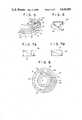
- FIGS. 8 to 10are enlarged plan views showing the positions of contact between contact pieces and said printed circuit when the mirror body is in the neutral position, the position of the rear turning limit, and the position of the front turning limit.
- an electrically foldable door mirror of the inventioncomprises a base 1 fixed to a door of a motor vehicle, a shaft 6 erected on said base 1, a mirror body 3 rotatably attached to said shaft 6, a pinion 18 of electric driving means 10 being engaged with a clutch gear 20 attached to the upper portion of said shaft 6, means for automatically stopping said electric driving means 10 being provided between one surface of a fixed clutch 21 fixed to the upper end of said shaft 6 and a surface of a mirror body 3 opposing said one surface of the fixed clutch 21, said stopping means comprising a printed circuit and contact pieces slidable thereon.
- the door mirror of the inventioncan be folded not only by automatic operation but also by manual operation.
- a switch provided inside the vehicleis manipulated to actuate the electric driving means 10 through a sequence circuit (not shown).
- the sequence circuitis controlled by the positions of the contact pieces relative to the printed circuit so as to stop the electric driving means 10 automatically when the mirror body 3 has come to the neutral position (erected position) or the position of the turning limit.
- the mirror body 3is forcibly turned by hand with the pinion 18 of the electric driving means 10 engaged with the clutch gear 20 attached to the shaft 6. Then, the lower clutch 25b is disengaged first, and the upper clutch 25a is disengaged next.
- both of the upper clutch 25a and the lower clutch 25bare disengaged at the same time so that the mirror body 3 is turned by the external force.
- the clutches 25a, 25bare adapted to operate effectively according to the force exerted on the mirror body 3.
- numeral 1represents a base fastened, for example, to the triangular corner of a door window of a motor vehicle by means of screws.
- Numeral 2represents a bracket extending approximately horizontally from the lower portion of the base 1.
- Numeral 3represents a mirror body.
- Numeral 4represents a mirror.
- Numeral 5represents a pivot of the mirror 4.
- Numeral 6represents a shaft erected on the bracket 2.
- the shaft 6Since the mirror body 3 illustrated in FIG. 1 contains an actuator 28 for changing the angle of reflection of the mirror 4, the shaft 6 has a central hole through which a harness 7 for the actuator 28 passes. When the mirror body 3 does not contain such an actuator, the shaft 6 is not required to be hollow.
- a frame 8is secured within the mirror body 3, and said actuator 28 is disposed approximately in the center of the frame 8.
- the frame 8supports, near the base 1, electric driving means 10 and a shaft bearing 12 into which the shaft 6 is inserted.
- the electric driving means 10comprises a reversible DC electric motor 15 and a gear box 16 containing reduction gears.
- a pinion 18is secured to the output shaft 17 of the gear box 16.
- the shaft bearing 12 of the frame 8is slightly tapered, and the shaft 6 has a taper portion corresponding thereto.
- the shaft bearing 12 of the frame 8is put on the taper portion of the shaft 6, the whole frame 8 is rotatable and axially slidable with relation to the shaft 6.
- the shaft 6has a cylindrical portion above said taper portion, and a clutch gear 20 engaged with said pinion 18 is attached to the cylindrical portion.
- the shaft 6has a narrow portion above said cylindrical portion, and a fixed clutch 21 is fixed to the narrow portion.
- the opposing surfaces of the clutch gear 20 and the fixed clutch 21form an upper clutch 25a.
- the upper clutch 25amay be, as shown in FIG. 2, a ball clutch comprising a plurality of (three, for example) holes respectively provided in the upper surface of the clutch gear 20 and the lower surface of the fixed clutch 21, and balls 22 fitted in said holes.
- the upper clutch 25amay comprise sidge-shaped catches or tooth-shaped catches (not shown).
- a coiled spring 24is disposed around the shaft bearing 12 so as to give a force of engagement to both of said upper clutch 25a and a lower clutch 25b described below.
- the lower clutch 25bis a ball clutch comprising holes provided in a stopper 26 around the root portion of the shaft 6 and balls 27 fitted in said holes.
- the engagement of the lower clutch 25bis made weaker than that of the upper clutch 25a by, for example, fitting the balls 27 of the lower clutch 25b more shallowly in the holes or making the balls 27 larger, as compared with the balls 22 of the upper clutch 25a.
- the lower clutch 25bis disengaged slightly earlier than the upper clutch 25a so that the mirror body 3 can be turned smoothly.
- the stopping meanscomprises the fixed clutch 21 fixed to the upper portion of the shaft 6, a printed circuit 33 provided on the upper surface of the fixed clutch 21, a holder 30 attached above the fixed clutch 21 to the pivotal center of the mirror body 3, and four contact pieces 36 provided on the periphery of the holder 30.
- the holder 30has a cap 38 on for the protection of said contact pieces 36.
- the central cylinder of the holder 30 passing through the central hole of the cap 38has an undercut 39, which is engaged with a recess 40 formed under said gear box 16.
- the printed circuit 33has two arc-shaped conductive plates 31, 32 having different radii, one being disposed on the inside of the other.
- the conductive plate 31contacts the contact pieces 36 having contacts B 1 , B 2 of a switch for detecting the position of the rear turning limit.
- the conductive plate 31is disposed on the outside of the other conductive plate 32, and has the shape of an arc with an angle of 340°.
- the conductive plate 32contacts the contact pieces 36 having contacts N 1 , N 2 of a switch for detecting the neutral position.
- the conductive plate 32has the shape of an arc with a shorter length (about 200°, phase being shifted) and a smaller radius as compared with said conductive plate 31.
- the printed circuit 33is provided on its periphery with three semicircular notches 41, in which projections 42 of said fixed clutch 21 are fitted to prevent rotation (FIGS. 4 and 5).
- Each contact piece 36comprises a substantially rectangular main portion and a leg portion 37 extending obliquely downward therefrom (FIG. 6).
- the main portionis supported on a supporting member 34 provided on the periphery of said holder 30.
- a terminal 35is soldered to the upper surface of said main body. See FIGS. 3 and 5.
- Said leg portion 37 of the contact piece 36has a shape similar to a right-angled triangle when seen from above, a portion near the vertex thereof being bent so as to serve as a contact.
- the contactis not in the central position of the contact piece 36.
- the contactcontacts the printed circuit 33 at different positions with respect to the radius thereof according as the contact piece 36 is attached to the supporting member 34 in the direction shown in FIG. 7A or in the opposite direction shown in FIG. 7B. That is, the contact of the contact piece 36 is in the opposite positions with respect to the circumferential direction and the radial direction according to the direction in which the contact piece 36 is attached. For example, if the contact pieces 36 having the contacts N 1 , N 2 for detecting the neutral position are attached in the direction shown in FIG.
- FIGS. 1 and 2show the state that the mirror body 3 is erected, that is, the mirror body 3 stays in the normal (neutral) position.
- the upper clutch 25a and the lower clutch 25bare respectively engaged by the force of the coiled spring 24.
- the contact pieces 36are in contact with the printed circuit 33 as shown in FIG. 4, and the DC electric motor 15 is stopped.
- the rotation of the DC electric motor 15is slowed down by the gear box 16 and transmitted through the pinion 18 to the clutch gear 20 so as to cause relative rotation to the shaft bearing 12 into which the shaft 6 is inserted.
- the upper clutch 25a between the clutch gear 20 and the fixed clutch 21is not disengaged. Therefore, the clutch gear 20 is not rotated and the pinion 18 rotates both round the clutch 20 and on its axis so as to turn the mirror body 3.
- FIGS. 8 to 10show the positions of contact between the contact pieces 36 and the printed circuit 33 when the mirror body 3 is in the neutral position, the position of the rear turning limit and the position of the front turning limit.
- the central point of each mark ⁇ in FIGS. 8 to 10shows the position of contact.
- both the contacts B 1 and B 2are in contact with the outer conductive plate 31 and said switch for detecting the position of the rear turning limit is closed.
- the contact N 1is not in contact with the inner conductive plate 32 and said switch for detecting the neutral position is open. Therefore, the DC electric motor 15 is stopped and the mirror body 3 is kept in the neutral (erected) position. In this state, if the operation switch (not shown) is turned on, the DC electric motor 15 is actuated and the mirror body 3 is turned backward because said switch for detecting the rear turning limit is closed. At this time, the contact pieces 36 turn clockwise.
- the contacts N 1 , N 2are in contact with the conductive plate 32 and the switch for detecting the neutral position is closed. Also, the contact B 1 is in contact with the conductive plate 31, but the contact B 2 is not in contact with the conductive plate 31, thus the switch for detecting the rear turning limit being open. Therefore, the DC electric motor 15 is stopped and the mirror body 3 is kept in the position of the rear turning limit. In this state, if the operation switch is turned on again, the DC electric motor 15 is reversed. Thus, the contact pieces 36 are turned counterclockwise and the mirror body 3 is returned to the neutral position.
- FIG. 10shows the positional relation between the contacts N 1 , N 2 , B 1 , B 2 and the conductive plates 31, 32 when the mirror body 3 is in the position of the front turning limit.
- the mirror body 3cannot be turned forward by automatic operation.
- the contacts N 1 , N 2are not in contact with the conductive plate 32 and the switch for detecting the neutral position is open, while the contacts B 1 , B 2 are in contact with the conductive plate 31 and the switch for detecting the position of the rear turning limit is closed.
- the mirror bodycan be turned by remotely controlling the electric driving means contained in the mirror body.
- the door mirrorhas means for automatically stopping the electric driving means, said stopping means being disposed between one surface of a fixed clutch fixed to the upper end of said shaft and a surface of a mirror body opposing said one surface of the fixed clutch, said stopping means comprising a printed circuit and contact pieces slidable thereon. Therefore, in the position of the turning limit, the switch for detecting the position of the turning limit is open, and the mirror body is automatically stopped and kept in this position. If the electric driving means is reversed by means of the operation switch, the mirror body is turned from the position of the turning limit to the neutral (erected) position and kept in the neutral position. Furthermore, since the pinion fixed to the output shaft of the electric driving means is engaged with the clutch gear attached to the upper portion of the shaft, the mirror body is given relative rotation on the shaft and is surely turned.
Landscapes
- Engineering & Computer Science (AREA)
- Multimedia (AREA)
- Mechanical Engineering (AREA)
- Rear-View Mirror Devices That Are Mounted On The Exterior Of The Vehicle (AREA)
- Optical Elements Other Than Lenses (AREA)
Abstract
Description
Claims (4)
Applications Claiming Priority (2)
| Application Number | Priority Date | Filing Date | Title |
|---|---|---|---|
| JP60-29472 | 1985-02-19 | ||
| JP60029472AJPS61191447A (en) | 1985-02-19 | 1985-02-19 | Electrically-operated retractable door mirror |
Publications (1)
| Publication Number | Publication Date |
|---|---|
| US4626083Atrue US4626083A (en) | 1986-12-02 |
Family
ID=12277037
Family Applications (1)
| Application Number | Title | Priority Date | Filing Date |
|---|---|---|---|
| US06/745,663Expired - Fee RelatedUS4626083A (en) | 1985-02-19 | 1985-06-17 | Electrically foldable door mirror |
Country Status (2)
| Country | Link |
|---|---|
| US (1) | US4626083A (en) |
| JP (1) | JPS61191447A (en) |
Cited By (32)
| Publication number | Priority date | Publication date | Assignee | Title |
|---|---|---|---|---|
| US4786157A (en)* | 1986-03-01 | 1988-11-22 | Aisin Seiki Kabushiki Kaisha | Electrically operated automobile mirror assembly |
| US4786156A (en)* | 1984-01-12 | 1988-11-22 | Ichikoh Industries Limited | Remote control side mirror device for vehicle |
| US4798967A (en)* | 1988-03-24 | 1989-01-17 | Murakami Kaimeido Co | Control system for foldable outside rearview mirror |
| US4815837A (en)* | 1986-11-26 | 1989-03-28 | Murakami Kaimeido Co., Ltd. | Actuator unit housing for rearview mirror |
| US4828215A (en)* | 1987-06-02 | 1989-05-09 | Mittelhaeuser Bernhard | External rearview mirror for vehicles |
| US4832477A (en)* | 1986-09-30 | 1989-05-23 | Aisin Seiki Kabushiki Kaisha | Door mirror assembly for automotive vehicles |
| US4893916A (en)* | 1987-02-10 | 1990-01-16 | Koito Seisakusho Co., Ltd. | Automatically stored vehicle mirror |
| US4975547A (en)* | 1986-10-13 | 1990-12-04 | Murakami Kameido Co., Ltd. | Multi-position electrical switch |
| US4981349A (en)* | 1989-09-01 | 1991-01-01 | Kabushiki Kaisha Matsuyama Seisakusho | Rearview mirror assembly for automobiles including positioning means with a recess surface extending uniformly horizontally |
| US4982926A (en)* | 1988-09-30 | 1991-01-08 | Aisin Seiki Kabushiki Kaisha | Retractable mirror apparatus |
| US5005797A (en)* | 1987-07-16 | 1991-04-09 | Ichikoh Industries, Ltd. | Door mirror for vehicles |
| DE4031032A1 (en)* | 1989-10-02 | 1991-04-25 | Aisin Seiki | TORQUE LIMITER ARRANGEMENT FOR A TURNING DEVICE |
| US5315442A (en)* | 1991-12-26 | 1994-05-24 | Murakami Kaimeido Co., Ltd. | Electrically foldable rearview mirrors |
| US5369530A (en)* | 1990-10-24 | 1994-11-29 | Ichikoh Industries Ltd. | Stay housable type motor driven mirror |
| US5432640A (en)* | 1990-06-04 | 1995-07-11 | Britax Rainsfords Pty Ltd. | Spigot type break-away mirror |
| US5432641A (en)* | 1992-09-16 | 1995-07-11 | Murakami Kaimeido Co., Ltd. | Electrically powered foldable outer rearview mirrors for motor vehicles |
| US5477392A (en)* | 1993-03-24 | 1995-12-19 | Murakami Kaimeido Co. Ltd. | Electrically powered foldable outer rearview mirror for a motor vehicle |
| US5557476A (en)* | 1991-06-17 | 1996-09-17 | Eiji Murakami | Foldable outside rearview mirror |
| US5579178A (en)* | 1994-04-19 | 1996-11-26 | Murakami Kaimeido Co., Ltd. | Electrically powered foldable rearview mirror for automobiles including a sealing structure for a driving unit |
| US5684646A (en)* | 1995-01-17 | 1997-11-04 | Lowell Engineering Corporation | Exterior mirror with single pivot power fold |
| US5703731A (en)* | 1995-01-17 | 1997-12-30 | Lowell Engineering Corporation | Exterior mirror with indexing and control pivoting |
| US5703732A (en)* | 1995-01-17 | 1997-12-30 | Lowell Engineering Corporation | Exterior mirror with indexing and control pivoting |
| US5828504A (en)* | 1994-11-26 | 1998-10-27 | Britax (Geco) S.A. | Exterior rearview mirror for a vehicle |
| US6059415A (en)* | 1998-01-29 | 2000-05-09 | Metagal Industria E Comercio Ltda | External rearview mirror with a retention device for holding the mirror in a predetermined position |
| US20020001148A1 (en)* | 2000-07-03 | 2002-01-03 | Hans-Joachim Fuchs | Pivoting outside mirror for a motor vehicle |
| EP1129907A3 (en)* | 2000-02-29 | 2003-09-03 | Bühler Motor GmbH | Exterior rear view mirror for vehicles |
| US6880940B1 (en)* | 2003-11-10 | 2005-04-19 | Honda Motor Co., Ltd. | Magnesium mirror base with countermeasures for galvanic corrosion |
| US20060023326A1 (en)* | 2003-05-27 | 2006-02-02 | Hiroyasu Onuki | Mirror device for vehicle |
| US20070211357A1 (en)* | 2003-11-10 | 2007-09-13 | Urick Kirk B | System for automatically positioning vehicle mirrors |
| US20070211354A1 (en)* | 2004-10-01 | 2007-09-13 | Murakami Corporation | Retractable door mirror |
| US20110141591A1 (en)* | 2009-12-11 | 2011-06-16 | Murakami Corporation | Common base for manually retractable and electrically retractable vehicle door mirrors, manually retractable vehicle door mirror, electrically retractable vehicle door mirror, and method for selectively manufacturing manually retractable/electrically retractable vehicle door mirror |
| US11135976B2 (en)* | 2019-09-20 | 2021-10-05 | Honda Motor Co., Ltd. | Vehicle door mirror assembly |
Families Citing this family (4)
| Publication number | Priority date | Publication date | Assignee | Title |
|---|---|---|---|---|
| JPS6237544U (en)* | 1985-08-26 | 1987-03-05 | ||
| JPS6237545U (en)* | 1985-08-26 | 1987-03-05 | ||
| JPS61150238U (en)* | 1985-03-11 | 1986-09-17 | ||
| JPS62134348A (en)* | 1985-12-07 | 1987-06-17 | Tokai Rika Co Ltd | Motor driven door mirror for vehicle |
Citations (6)
| Publication number | Priority date | Publication date | Assignee | Title |
|---|---|---|---|---|
| US3937563A (en)* | 1974-03-21 | 1976-02-10 | Frabe Donald A | Remote controlled mirror assembly for vehicle |
| US4158483A (en)* | 1975-07-09 | 1979-06-19 | Harman International Industries, Inc. | Remote controlled rearview mirror |
| US4380370A (en)* | 1980-05-06 | 1983-04-19 | Mittelhaeuser Bernhard | Outside rear view mirror for motor vehicles |
| US4464017A (en)* | 1981-08-31 | 1984-08-07 | Ichikoh Industries Limited | Remotely controlled mirror apparatus for motor vehicles |
| US4504116A (en)* | 1981-06-21 | 1985-03-12 | Parker-Hannifin Corporation | Rearview mirror positionable by remote control |
| US4558930A (en)* | 1984-04-04 | 1985-12-17 | Deedrick Harold | Truck mirror adjustable in the horizontal direction |
Family Cites Families (2)
| Publication number | Priority date | Publication date | Assignee | Title |
|---|---|---|---|---|
| JPS60179352A (en)* | 1984-02-27 | 1985-09-13 | Tokai Rika Co Ltd | Electromotive device for retractable mirror visor |
| JPH0417388Y2 (en)* | 1984-10-16 | 1992-04-17 |
- 1985
- 1985-02-19JPJP60029472Apatent/JPS61191447A/enactiveGranted
- 1985-06-17USUS06/745,663patent/US4626083A/ennot_activeExpired - Fee Related
Patent Citations (6)
| Publication number | Priority date | Publication date | Assignee | Title |
|---|---|---|---|---|
| US3937563A (en)* | 1974-03-21 | 1976-02-10 | Frabe Donald A | Remote controlled mirror assembly for vehicle |
| US4158483A (en)* | 1975-07-09 | 1979-06-19 | Harman International Industries, Inc. | Remote controlled rearview mirror |
| US4380370A (en)* | 1980-05-06 | 1983-04-19 | Mittelhaeuser Bernhard | Outside rear view mirror for motor vehicles |
| US4504116A (en)* | 1981-06-21 | 1985-03-12 | Parker-Hannifin Corporation | Rearview mirror positionable by remote control |
| US4464017A (en)* | 1981-08-31 | 1984-08-07 | Ichikoh Industries Limited | Remotely controlled mirror apparatus for motor vehicles |
| US4558930A (en)* | 1984-04-04 | 1985-12-17 | Deedrick Harold | Truck mirror adjustable in the horizontal direction |
Cited By (37)
| Publication number | Priority date | Publication date | Assignee | Title |
|---|---|---|---|---|
| US4786156A (en)* | 1984-01-12 | 1988-11-22 | Ichikoh Industries Limited | Remote control side mirror device for vehicle |
| US4786157A (en)* | 1986-03-01 | 1988-11-22 | Aisin Seiki Kabushiki Kaisha | Electrically operated automobile mirror assembly |
| US4832477A (en)* | 1986-09-30 | 1989-05-23 | Aisin Seiki Kabushiki Kaisha | Door mirror assembly for automotive vehicles |
| US4975547A (en)* | 1986-10-13 | 1990-12-04 | Murakami Kameido Co., Ltd. | Multi-position electrical switch |
| US4815837A (en)* | 1986-11-26 | 1989-03-28 | Murakami Kaimeido Co., Ltd. | Actuator unit housing for rearview mirror |
| US4893916A (en)* | 1987-02-10 | 1990-01-16 | Koito Seisakusho Co., Ltd. | Automatically stored vehicle mirror |
| US4828215A (en)* | 1987-06-02 | 1989-05-09 | Mittelhaeuser Bernhard | External rearview mirror for vehicles |
| US5005797A (en)* | 1987-07-16 | 1991-04-09 | Ichikoh Industries, Ltd. | Door mirror for vehicles |
| US4798967A (en)* | 1988-03-24 | 1989-01-17 | Murakami Kaimeido Co | Control system for foldable outside rearview mirror |
| US4982926A (en)* | 1988-09-30 | 1991-01-08 | Aisin Seiki Kabushiki Kaisha | Retractable mirror apparatus |
| US4981349A (en)* | 1989-09-01 | 1991-01-01 | Kabushiki Kaisha Matsuyama Seisakusho | Rearview mirror assembly for automobiles including positioning means with a recess surface extending uniformly horizontally |
| DE4031032A1 (en)* | 1989-10-02 | 1991-04-25 | Aisin Seiki | TORQUE LIMITER ARRANGEMENT FOR A TURNING DEVICE |
| US5190499A (en)* | 1989-10-02 | 1993-03-02 | Aisin Seiki K.K. | Torque limiter arrangement for rotating device |
| US5432640A (en)* | 1990-06-04 | 1995-07-11 | Britax Rainsfords Pty Ltd. | Spigot type break-away mirror |
| US5369530A (en)* | 1990-10-24 | 1994-11-29 | Ichikoh Industries Ltd. | Stay housable type motor driven mirror |
| US5557476A (en)* | 1991-06-17 | 1996-09-17 | Eiji Murakami | Foldable outside rearview mirror |
| US5315442A (en)* | 1991-12-26 | 1994-05-24 | Murakami Kaimeido Co., Ltd. | Electrically foldable rearview mirrors |
| US5432641A (en)* | 1992-09-16 | 1995-07-11 | Murakami Kaimeido Co., Ltd. | Electrically powered foldable outer rearview mirrors for motor vehicles |
| US5477392A (en)* | 1993-03-24 | 1995-12-19 | Murakami Kaimeido Co. Ltd. | Electrically powered foldable outer rearview mirror for a motor vehicle |
| US5579178A (en)* | 1994-04-19 | 1996-11-26 | Murakami Kaimeido Co., Ltd. | Electrically powered foldable rearview mirror for automobiles including a sealing structure for a driving unit |
| US5828504A (en)* | 1994-11-26 | 1998-10-27 | Britax (Geco) S.A. | Exterior rearview mirror for a vehicle |
| US5684646A (en)* | 1995-01-17 | 1997-11-04 | Lowell Engineering Corporation | Exterior mirror with single pivot power fold |
| US5703731A (en)* | 1995-01-17 | 1997-12-30 | Lowell Engineering Corporation | Exterior mirror with indexing and control pivoting |
| US5703732A (en)* | 1995-01-17 | 1997-12-30 | Lowell Engineering Corporation | Exterior mirror with indexing and control pivoting |
| US6059415A (en)* | 1998-01-29 | 2000-05-09 | Metagal Industria E Comercio Ltda | External rearview mirror with a retention device for holding the mirror in a predetermined position |
| EP1129907A3 (en)* | 2000-02-29 | 2003-09-03 | Bühler Motor GmbH | Exterior rear view mirror for vehicles |
| US20020001148A1 (en)* | 2000-07-03 | 2002-01-03 | Hans-Joachim Fuchs | Pivoting outside mirror for a motor vehicle |
| US7393111B2 (en)* | 2000-07-03 | 2008-07-01 | Donnelly Hohe Gmbh & Co. Kg | Pivoting outside mirror for a motor vehicle |
| US20060023326A1 (en)* | 2003-05-27 | 2006-02-02 | Hiroyasu Onuki | Mirror device for vehicle |
| US6880940B1 (en)* | 2003-11-10 | 2005-04-19 | Honda Motor Co., Ltd. | Magnesium mirror base with countermeasures for galvanic corrosion |
| US20050099711A1 (en)* | 2003-11-10 | 2005-05-12 | Honda Motor Co., Ltd. | Magnesium mirror base with countermeasures for galvanic corrosion |
| US20070211357A1 (en)* | 2003-11-10 | 2007-09-13 | Urick Kirk B | System for automatically positioning vehicle mirrors |
| US7474203B2 (en) | 2003-11-10 | 2009-01-06 | Urick Kirk B | System for automatically positioning vehicle mirrors |
| US20070211354A1 (en)* | 2004-10-01 | 2007-09-13 | Murakami Corporation | Retractable door mirror |
| US20110141591A1 (en)* | 2009-12-11 | 2011-06-16 | Murakami Corporation | Common base for manually retractable and electrically retractable vehicle door mirrors, manually retractable vehicle door mirror, electrically retractable vehicle door mirror, and method for selectively manufacturing manually retractable/electrically retractable vehicle door mirror |
| US8894223B2 (en)* | 2009-12-11 | 2014-11-25 | Murakami Corporation | Common base for manually retractable and electrically retractable vehicle door mirrors, manually retractable vehicle door mirror, electrically retractable vehicle door mirror, and method for selectively manufacturing manually retractable/electrically retractable vehicle door mirror |
| US11135976B2 (en)* | 2019-09-20 | 2021-10-05 | Honda Motor Co., Ltd. | Vehicle door mirror assembly |
Also Published As
| Publication number | Publication date |
|---|---|
| JPH0428572B2 (en) | 1992-05-14 |
| JPS61191447A (en) | 1986-08-26 |
Similar Documents
| Publication | Publication Date | Title |
|---|---|---|
| US4626083A (en) | Electrically foldable door mirror | |
| US4626084A (en) | Electrically foldable door mirror | |
| EP0305590B1 (en) | Electrically foldable door mirror | |
| US7883224B2 (en) | Vehicle outside mirror device | |
| US5384660A (en) | Foldable outside rearview mirror | |
| US5594590A (en) | Mirror-housing positioning device for car rearview mirror | |
| US5432641A (en) | Electrically powered foldable outer rearview mirrors for motor vehicles | |
| EP1369301B1 (en) | Outer mirror for vehicle | |
| EP0528418B1 (en) | Electrically remote-controlled mirror assembly | |
| EP0616923A1 (en) | Electrically foldable outer rearview mirror for a motor vehicle | |
| US5150637A (en) | Transfer case shifting apparatus for four wheel drive vehicle | |
| JPH0567458B2 (en) | ||
| US5640281A (en) | Outside foldable rearview mirror for vehicle | |
| US5148325A (en) | Vehicular external mirror assembly | |
| CN2910685Y (en) | Vehicle turn-indicator system | |
| JPH0418574B2 (en) | ||
| JP3309708B2 (en) | Outer mirror device for vehicles | |
| JPH0431145A (en) | Automobile rear view mirror device | |
| JPH0512112Y2 (en) | ||
| JPS5848194Y2 (en) | Rear mirror device | |
| JPH0244590Y2 (en) | ||
| JPH0425902B2 (en) | ||
| KR940000043B1 (en) | Side mirror with power rotating device | |
| JPH0659780B2 (en) | Drive system for vehicle roof | |
| KR920005583Y1 (en) | Automotive rearview mirror with auto-expanding range |
Legal Events
| Date | Code | Title | Description |
|---|---|---|---|
| AS | Assignment | Owner name:MURAKAMI KAIMEIDO CO., LTD., 12-25, MIYAMOTO-CHO, Free format text:ASSIGNMENT OF ASSIGNORS INTEREST.;ASSIGNORS:NAKAYAMA, KIYOSHI;ITO, YASUTOSHI;KUMAI, TOSHIYUKI;REEL/FRAME:004418/0353 Effective date:19850606 Owner name:MURAKAMI KAIMEIDO CO., LTD.,JAPAN Free format text:ASSIGNMENT OF ASSIGNORS INTEREST;ASSIGNORS:NAKAYAMA, KIYOSHI;ITO, YASUTOSHI;KUMAI, TOSHIYUKI;REEL/FRAME:004418/0353 Effective date:19850606 | |
| FEPP | Fee payment procedure | Free format text:PAYOR NUMBER ASSIGNED (ORIGINAL EVENT CODE: ASPN); ENTITY STATUS OF PATENT OWNER: LARGE ENTITY | |
| FPAY | Fee payment | Year of fee payment:4 | |
| FPAY | Fee payment | Year of fee payment:8 | |
| REMI | Maintenance fee reminder mailed | ||
| LAPS | Lapse for failure to pay maintenance fees | ||
| FP | Lapsed due to failure to pay maintenance fee | Effective date:19981202 | |
| FEPP | Fee payment procedure | Free format text:PAYER NUMBER DE-ASSIGNED (ORIGINAL EVENT CODE: RMPN); ENTITY STATUS OF PATENT OWNER: LARGE ENTITY Free format text:PAYOR NUMBER ASSIGNED (ORIGINAL EVENT CODE: ASPN); ENTITY STATUS OF PATENT OWNER: LARGE ENTITY | |
| STCH | Information on status: patent discontinuation | Free format text:PATENT EXPIRED DUE TO NONPAYMENT OF MAINTENANCE FEES UNDER 37 CFR 1.362 |