US4625477A - Display wall formed of readily attachable and detachable panels - Google Patents
Display wall formed of readily attachable and detachable panelsDownload PDFInfo
- Publication number
- US4625477A US4625477AUS06/808,765US80876585AUS4625477AUS 4625477 AUS4625477 AUS 4625477AUS 80876585 AUS80876585 AUS 80876585AUS 4625477 AUS4625477 AUS 4625477A
- Authority
- US
- United States
- Prior art keywords
- standard
- structural members
- edge
- wall panel
- slots
- Prior art date
- Legal status (The legal status is an assumption and is not a legal conclusion. Google has not performed a legal analysis and makes no representation as to the accuracy of the status listed.)
- Expired - Fee Related
Links
- 238000010276constructionMethods0.000claimsabstractdescription22
- 229910052751metalInorganic materials0.000claimsdescription17
- 239000002184metalSubstances0.000claimsdescription17
- 239000000463materialSubstances0.000description5
- 230000000295complement effectEffects0.000description3
- 229910052782aluminiumInorganic materials0.000description2
- XAGFODPZIPBFFR-UHFFFAOYSA-NaluminiumChemical compound[Al]XAGFODPZIPBFFR-UHFFFAOYSA-N0.000description2
- 229910000831SteelInorganic materials0.000description1
- 230000013011matingEffects0.000description1
- 230000004048modificationEffects0.000description1
- 238000012986modificationMethods0.000description1
- 230000002787reinforcementEffects0.000description1
- 230000000717retained effectEffects0.000description1
- 239000010959steelSubstances0.000description1
Images


Classifications
- G—PHYSICS
- G09—EDUCATION; CRYPTOGRAPHY; DISPLAY; ADVERTISING; SEALS
- G09F—DISPLAYING; ADVERTISING; SIGNS; LABELS OR NAME-PLATES; SEALS
- G09F15/00—Boards, hoardings, pillars, or like structures for notices, placards, posters, or the like
- G09F15/0006—Boards, hoardings, pillars, or like structures for notices, placards, posters, or the like planar structures comprising one or more panels
- E—FIXED CONSTRUCTIONS
- E04—BUILDING
- E04B—GENERAL BUILDING CONSTRUCTIONS; WALLS, e.g. PARTITIONS; ROOFS; FLOORS; CEILINGS; INSULATION OR OTHER PROTECTION OF BUILDINGS
- E04B1/00—Constructions in general; Structures which are not restricted either to walls, e.g. partitions, or floors or ceilings or roofs
- E04B1/38—Connections for building structures in general
- E04B1/61—Connections for building structures in general of slab-shaped building elements with each other
- E04B1/6108—Connections for building structures in general of slab-shaped building elements with each other the frontal surfaces of the slabs connected together
- E04B1/612—Connections for building structures in general of slab-shaped building elements with each other the frontal surfaces of the slabs connected together by means between frontal surfaces
- E04B1/6183—Connections for building structures in general of slab-shaped building elements with each other the frontal surfaces of the slabs connected together by means between frontal surfaces with rotatable locking means co-operating with a recess
- E—FIXED CONSTRUCTIONS
- E04—BUILDING
- E04B—GENERAL BUILDING CONSTRUCTIONS; WALLS, e.g. PARTITIONS; ROOFS; FLOORS; CEILINGS; INSULATION OR OTHER PROTECTION OF BUILDINGS
- E04B2/00—Walls, e.g. partitions, for buildings; Wall construction with regard to insulation; Connections specially adapted to walls
- E04B2/74—Removable non-load-bearing partitions; Partitions with a free upper edge
- E04B2/7407—Removable non-load-bearing partitions; Partitions with a free upper edge assembled using frames with infill panels or coverings only; made-up of panels and a support structure incorporating posts
- E04B2/7448—Removable non-load-bearing partitions; Partitions with a free upper edge assembled using frames with infill panels or coverings only; made-up of panels and a support structure incorporating posts with separate framed panels without intermediary posts, extending from floor to ceiling
Definitions
- the present inventionrelates to a display wall structure which may be free-standing or anchored to a wall, and more particularly refers to a wall structure formed of individual panels which are readily attached and detached.
- Vertical display wallsare widely used in commercial establishments for the display of a wide variety of items.
- the display apparatusis universal and may be assembled to take a wide variety of shape and form configurations to accommodate a particular size and motif in a display area or showroom.
- the wallsare generally formed of a plurality of panels which are adapted to be readily assembled and disassembled, and yet still provide a function and aesthetic appealing means for displaying a wide variety of articles.
- a wall of the type describedis disclosed and claimed in U.S. Pat. No. 4,434,900.
- the edges of the individual panelsare assembled to each other edge-wise by means of keyholes provided in the edge of one panel which engage screwheads provided in a post or another panel.
- a wall structurecomprised of a plurality of wall panels and metal standards or posts which are easily connected to each other by means of rotary latches retained in mortises provided in the edges of the panel members adapted to engage slots provided in metal standards or post structures or other panel edges.
- the structuresare engaged by sliding them together without necessarily lifting any of them, inserting a key in an aperture of the latch mechanism, and rotating the key until an arcuate latch member engages slots provided in the standard of an adjacent member and latches the two members together.
- the latching structurehas the advantage that it is recessed within the edges of the panels and therefore does not detract from the aesthetic appearance of the panels.
- the latchesmay be readily engaged and disengaged by a simple rotation of the key inserted in the key aperture provided in the latch and in the panel.
- FIG. 1is a perspective view of a modular wall structure according to the invention, assembled from a plurality of wall panels, pilasters and standards.
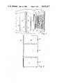
- FIG. 2is an elevational view of a single wall panel.
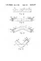
- FIG. 3is a perspective fragmentary view of a vertical standard according to the invention.
- FIG. 4is a fragmentary front view of the standard shown in FIG. 3.
- FIG. 5is a left-edge view of the standard.
- FIG. 6is an end view of a standard as shown in FIGS. 3-5.
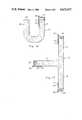
- FIG. 7is a perspective view of a lock assembly according to the invention.
- FIG. 8is an elevational view of the locking mechanism shown in FIG. 7.
- FIG. 9is an elevational view, partly broken away, of a joint between two wall panels with the bolt in unlocked position.
- FIG. 10is an elevational view, partly broken away, of the structure shown in FIG. 9 with the bolt in locked position.
- FIG. 11is a cross-sectional view of a joint between two wall panels.
- FIG. 12is a cross-sectional view of a wall panel being mortised at both edges to receive a bolt lock.
- FIG. 13is a fragmentary cross-sectional view of a wall panel having a standard at both edges.
- FIG. 14is a pilaster in the form of an obtuse angle having a standard at both edges.
- FIG. 15is a cross-sectional view of a pilaster in the form of a right angle having a mortise at one edge and a standard at the other edge.
- FIG. 16is a pilaster of U-shaped cross-section having a mortise at one edge and a standard at the other, and
- FIG. 17is a cross-sectional view of a pilaster having a T-shaped cross-section with a standard mounted at each edge.
- a modular wall panel construction 10comprising a plurality of smooth wall panels 11, 12, 13 and 14, and display panels 15, 16 and 17 having horizontal grooves for mounting display brackets.
- the corners of the modular constructionare formed by angular pilasters 18 and 19.
- Each jointis formed by a standard 20 co-operating with bolt locks mounted in mortised recesses at the edges of the complementary mating structure.
- the standards 20are preferably formed of a metal such as steel or aluminum, but may be formed of other suitable strong materials such as various plastic materials.
- a standard 20comprising a tubular portion 26 formed of a rear plate 31 terminating in an attachment flange 27 on one side, and a guide flange 28 which is smaller than the attachment flange.
- the remainder of the tubular body portion 26is formed of a front wall 21 and sidewalls 22 and 23.
- the structuredefines a central channel 24.
- the sidewall 22is provided with pairs of slots 29 at each position complementary with the position on the adjoining structural member containing bolt locks 25 mortised therein.
- the front wall 21may be provided with slots 30 for receiving mounting brackets for supporting shelving or display articles. As shown in FIG.
- FIG. 6illustrates the presence of a fillet 34 in the sidewall 22 where the slots 29 are placed in order to provide reinforcement for engaging the latch of the bolt lock 25.
- a bolt lock 25 assemblyis shown, the bolt lock 25 generally being known in the trade as a GIRO-bolt lock marketed by the Hafele America Company, High Point, N.C.
- the structureincludes a housing 40 having a mounting bracket 41 affixed thereto.
- a rotatable hub 42is mounted in the housing and is provided with a hexagonal aperture 43.
- a radial arm 44shown in FIG. 8, is connected to the hub 42 at one end and at the other having an arcuate bolt 45 extending through an aperture 48, and adapted, upon rotation of the hub 42, to enter a second aperture 49 provided in the mounting plate 41.
- the assemblyadditionally includes an Allen crank wrench 47 having a hexagonal cross-section adapted to be inserted into the hexagonal aperture 43 of the hub 42.
- FIGS. 9, 10 and 11a pair of wall panels 11 and 12 are shown.
- the wall panel 12has a metal standard 20 affixed thereto by means of screws 33 inserted through apertures 32.
- the wall panel 11has a plurality of mortised recesses 35 provided therein in which are mounted rotary bolt locks 25 affixed to the wall panel 11 by screws 50.
- the hub 42has been rotated by inserting the crankshaped Allen wrench 47 into the hexagonal aperture 43 and turning the crank until the arcuate bolt 45 has just entered the first slot 29 of the metal standard 20.
- FIG. 10shows the assembly after the crank has been further rotated and the arcuate bolt 45 has penetrated and emerged from the second slot 29a of the pair of slots of the metal standard 20. In this condition the two walls are firmly locked together and cannot be pulled apart. The locked condition is further shown in FIG. 11.
- the modular wall panel construction of the present inventionis extremely versatile. Joints may be formed between two doors, between two wall panels of many different styles such as decorative wall panels and display-type wall panels which have grooves provided therein for mounting brackets to sustain displays and shelves.
- one structural memberhas a standard according to the invention affixed thereto by means of screws or other suitable fastening means, and the other structural member must have mortises provided in a plurality of positions in which rotary bolt locks are inserted and affixed.
- each panelmay be provided with one metal standard at one edge and a plurality of rotary bolt locks at the other edge, as shown and described in FIGS. 9-11.
- a wall panel 51may be provided having mortises 52 and 53 in which rotary bolt locks 25 according to the invention may be provided at both edges. The panel may then be connected at both ends to structural members having standards.
- FIG. 13shows a wall panel 58 having standards 20 mounted one at each edge. Each edge may be then mounted to another structural member which has a plurality of rotary bolt locks 25 mounted therein.
- the modular wall panel construction of the present inventionmay be affixed by means of suitable brackets to a permanent wall structure, or, alternatively, may be free-standing. In order for the structure to be free-standing, some of the wall panels must be oriented at an angle with respect to the others.
- the present inventionincludes structural members in the form of pilasters or posts.
- the pilastersmay be provided with any desired angular shape, and may have either standards or rotary bolt locks at its edges.
- FIG. 14is shown a pilaster 60 whose legs are at an obtuse angle with respect to each other. Affixed to the ends of the pilaster are a pair of standards 20. Alternatively, a plurality of rotary bolt locks 25 may be substituted at one or both edges.
- FIG. 15is shown a pilaster 61 in the form of a right angle.
- a plurality of mortises 62are provided at one edge adapted to receive a plurality of rotary bolt locks 25.
- a standard 20is affixed to the other edge.
- Wall panelsmay then be affixed to the edges of the pilaster by means of complementary locking means. Since the walls affixed to the pilaster 61 will be at right angles, the structure will be free-standing.
- a pilaster 65having a U-shaped cross-section.
- the structurecomprises legs 66 and 67, one having a mortise 68 provided to receive a bolt lock 25 and the other being provided with a metal standard 20 adapted to be attached to wall panels having bolt locks 25.
- a pilaster 70having a T-shaped cross-section comprised of legs 71, 72 and 73.
- Metal standards 20are provided at the end of each leg for being connected to wall panels having bolt locks.
- the modular wall panel instruction of the present inventionhas a number of advantages over the structures of the prior art.
- Wall panelsmay be connected to wall panels and wall panels may be connected to pilasters. It is only necessary that the engaging edge of one structural member be provided with a metal standard having appropriately placed pairs of engagement slots, notches that and the edge of the other structural member be provided with a plurality of bolt locks at positions where they may engage the slots of the metal standard. A simple rotation of the Allen wrench crank will then firmly lock the members together.
- the bolt locksare commercially made and may be readily obtained in the market.
- the metal standardmay be readily extruded from a material such as aluminum or even a strong plastic material, and then machined to provide the proper engagement slots. Modular structures may then be sssembled such as the one shown in FIG. 1.
Landscapes
- Engineering & Computer Science (AREA)
- Architecture (AREA)
- Physics & Mathematics (AREA)
- Electromagnetism (AREA)
- Civil Engineering (AREA)
- Structural Engineering (AREA)
- General Physics & Mathematics (AREA)
- Theoretical Computer Science (AREA)
- Connection Of Plates (AREA)
- Joining Of Building Structures In Genera (AREA)
Abstract
Description
Claims (18)
Priority Applications (2)
| Application Number | Priority Date | Filing Date | Title |
|---|---|---|---|
| US06/808,765US4625477A (en) | 1985-12-13 | 1985-12-13 | Display wall formed of readily attachable and detachable panels |
| CA000517506ACA1281160C (en) | 1985-12-13 | 1986-09-04 | Display wall formed of readily attachable and detachable panels |
Applications Claiming Priority (1)
| Application Number | Priority Date | Filing Date | Title |
|---|---|---|---|
| US06/808,765US4625477A (en) | 1985-12-13 | 1985-12-13 | Display wall formed of readily attachable and detachable panels |
Publications (1)
| Publication Number | Publication Date |
|---|---|
| US4625477Atrue US4625477A (en) | 1986-12-02 |
Family
ID=25199665
Family Applications (1)
| Application Number | Title | Priority Date | Filing Date |
|---|---|---|---|
| US06/808,765Expired - Fee RelatedUS4625477A (en) | 1985-12-13 | 1985-12-13 | Display wall formed of readily attachable and detachable panels |
Country Status (2)
| Country | Link |
|---|---|
| US (1) | US4625477A (en) |
| CA (1) | CA1281160C (en) |
Cited By (27)
| Publication number | Priority date | Publication date | Assignee | Title |
|---|---|---|---|---|
| US4865111A (en)* | 1988-07-26 | 1989-09-12 | Nimlok Company | Display system |
| US4876835A (en)* | 1984-09-10 | 1989-10-31 | Herman Miller, Inc. | Work space management system |
| US4918879A (en)* | 1987-05-29 | 1990-04-24 | Commercial And Architectural Products, Inc. | Merchandising wall structure including readily attachable and detachable panels and having plastic reveals |
| USD323715S (en) | 1987-06-01 | 1992-02-04 | Commercial and Architectural Products Company, Inc. | Merchandising display wall standard |
| US5638653A (en)* | 1994-06-10 | 1997-06-17 | Societe De Fabrication Et De Diffusion | System for fitting panels without visible fixing means |
| WO1997039200A1 (en)* | 1996-04-12 | 1997-10-23 | Max Girbinger | Partition wall system for commercial premises |
| US5687859A (en)* | 1995-03-06 | 1997-11-18 | Channel-Kor Systems, Inc. | Non-racking panel display device |
| US5694729A (en)* | 1994-09-16 | 1997-12-09 | Panel Concepts, Inc. | Wall partition connector |
| WO1998027289A1 (en)* | 1996-12-16 | 1998-06-25 | Amisk Technologies Inc. | Building system |
| US5899035A (en)* | 1997-05-15 | 1999-05-04 | Steelcase, Inc. | Knock-down portable partition system |
| US6029831A (en)* | 1995-03-06 | 2000-02-29 | Miller; Melvin M. | Non-racking panel display device |
| US6079754A (en)* | 1998-02-20 | 2000-06-27 | Alexy; Fred H. | Latching assembly for insulation panels |
| US6126358A (en)* | 1998-07-22 | 2000-10-03 | Shaw Industries, Inc. | Furniture panel stabilizer |
| US6442909B2 (en) | 1996-12-24 | 2002-09-03 | Steelcase Development Corporation | Knock-down portable partition system |
| US20030056413A1 (en)* | 2001-08-24 | 2003-03-27 | Wiemer James A. | Display system |
| US6546684B2 (en) | 1998-04-15 | 2003-04-15 | Steelcase Development Corporation | Partition panel |
| US6626017B2 (en)* | 2001-07-13 | 2003-09-30 | Carrier Corporation | Locking mechanism for air handler (AHU) cabinet |
| US6848589B2 (en) | 2002-07-19 | 2005-02-01 | Opto International, Inc. | Dimple perforated wall panel system |
| US6910306B2 (en) | 1996-12-24 | 2005-06-28 | Steelcase Development Corporation | Knock-down portable partition system |
| US20060123722A1 (en)* | 2002-07-29 | 2006-06-15 | Bo Stenvall | Insulating glass fastener |
| US20060137260A1 (en)* | 2004-09-02 | 2006-06-29 | Jo Shernaman | Modular wall, inventory display and product and service marketing systems |
| US7310918B1 (en)* | 1997-05-28 | 2007-12-25 | Knoll, Inc. | Hybrid office panel construction for a modular office furniture system |
| US20080054241A1 (en)* | 2006-09-05 | 2008-03-06 | Jan Christian Mangelsen | Safety fence for robotics |
| US20080302027A1 (en)* | 2006-01-04 | 2008-12-11 | David Eric Appleford | Building Panel |
| US20110232850A1 (en)* | 2010-03-24 | 2011-09-29 | Bellcomb Technologies Incorporated | Modular panel assembly |
| US20110296660A1 (en)* | 2010-06-07 | 2011-12-08 | Orbus | Display Support Structure And Method |
| USD693483S1 (en) | 2012-06-06 | 2013-11-12 | Marlite, Inc. | Edge trim for a wall panel system |
Citations (10)
| Publication number | Priority date | Publication date | Assignee | Title |
|---|---|---|---|---|
| US2081368A (en)* | 1935-07-11 | 1937-05-25 | Johns Manville | Wall assembly and stud |
| CA650810A (en)* | 1962-10-23 | Sunshine Waterloo Co. Limited | Office partition structure | |
| US3280522A (en)* | 1963-09-16 | 1966-10-25 | Dow Chemical Co | Building panels and fastener means therefor |
| US3332182A (en)* | 1964-12-03 | 1967-07-25 | Interstate Ind Inc | Partition stud and spring assembly |
| US4020613A (en)* | 1975-07-02 | 1977-05-03 | Reynolds Frank L | Fastener |
| US4223500A (en)* | 1978-05-10 | 1980-09-23 | Clark Howard K | Insulation molded, load bearing, prefabricated panels |
| US4334374A (en)* | 1981-03-26 | 1982-06-15 | The Mead Corporation | Means for attaching a panel to an upright |
| US4370838A (en)* | 1980-08-14 | 1983-02-01 | The Columbus Show Case Company | Curtain wall |
| US4434900A (en)* | 1983-01-25 | 1984-03-06 | Masonite Corporation | Free standing article display apparatus |
| US4493174A (en)* | 1982-06-07 | 1985-01-15 | Artafax Systems Limited, Inc. | Dismountable room partition |
- 1985
- 1985-12-13USUS06/808,765patent/US4625477A/ennot_activeExpired - Fee Related
- 1986
- 1986-09-04CACA000517506Apatent/CA1281160C/ennot_activeExpired - Lifetime
Patent Citations (10)
| Publication number | Priority date | Publication date | Assignee | Title |
|---|---|---|---|---|
| CA650810A (en)* | 1962-10-23 | Sunshine Waterloo Co. Limited | Office partition structure | |
| US2081368A (en)* | 1935-07-11 | 1937-05-25 | Johns Manville | Wall assembly and stud |
| US3280522A (en)* | 1963-09-16 | 1966-10-25 | Dow Chemical Co | Building panels and fastener means therefor |
| US3332182A (en)* | 1964-12-03 | 1967-07-25 | Interstate Ind Inc | Partition stud and spring assembly |
| US4020613A (en)* | 1975-07-02 | 1977-05-03 | Reynolds Frank L | Fastener |
| US4223500A (en)* | 1978-05-10 | 1980-09-23 | Clark Howard K | Insulation molded, load bearing, prefabricated panels |
| US4370838A (en)* | 1980-08-14 | 1983-02-01 | The Columbus Show Case Company | Curtain wall |
| US4334374A (en)* | 1981-03-26 | 1982-06-15 | The Mead Corporation | Means for attaching a panel to an upright |
| US4493174A (en)* | 1982-06-07 | 1985-01-15 | Artafax Systems Limited, Inc. | Dismountable room partition |
| US4434900A (en)* | 1983-01-25 | 1984-03-06 | Masonite Corporation | Free standing article display apparatus |
Non-Patent Citations (2)
| Title |
|---|
| Brochure (2 Pages) Hafele America (Giro Bolt Lock) 1/84.* |
| Brochure (2 Pages)-Hafele America (Giro-Bolt Lock) 1/84. |
Cited By (47)
| Publication number | Priority date | Publication date | Assignee | Title |
|---|---|---|---|---|
| US4876835A (en)* | 1984-09-10 | 1989-10-31 | Herman Miller, Inc. | Work space management system |
| US5038539A (en)* | 1984-09-10 | 1991-08-13 | Herman Miller, Inc. | Work space management system |
| US4918879A (en)* | 1987-05-29 | 1990-04-24 | Commercial And Architectural Products, Inc. | Merchandising wall structure including readily attachable and detachable panels and having plastic reveals |
| USD323715S (en) | 1987-06-01 | 1992-02-04 | Commercial and Architectural Products Company, Inc. | Merchandising display wall standard |
| US4865111A (en)* | 1988-07-26 | 1989-09-12 | Nimlok Company | Display system |
| US5638653A (en)* | 1994-06-10 | 1997-06-17 | Societe De Fabrication Et De Diffusion | System for fitting panels without visible fixing means |
| US5694729A (en)* | 1994-09-16 | 1997-12-09 | Panel Concepts, Inc. | Wall partition connector |
| US6029831A (en)* | 1995-03-06 | 2000-02-29 | Miller; Melvin M. | Non-racking panel display device |
| US5687859A (en)* | 1995-03-06 | 1997-11-18 | Channel-Kor Systems, Inc. | Non-racking panel display device |
| WO1997039200A1 (en)* | 1996-04-12 | 1997-10-23 | Max Girbinger | Partition wall system for commercial premises |
| WO1998027289A1 (en)* | 1996-12-16 | 1998-06-25 | Amisk Technologies Inc. | Building system |
| US7448168B2 (en) | 1996-12-24 | 2008-11-11 | Steelcase Inc. | Knock-down portable partition system |
| US7565772B2 (en) | 1996-12-24 | 2009-07-28 | Steelcase, Inc. | Knock-down portable partition system |
| US6442909B2 (en) | 1996-12-24 | 2002-09-03 | Steelcase Development Corporation | Knock-down portable partition system |
| US6910306B2 (en) | 1996-12-24 | 2005-06-28 | Steelcase Development Corporation | Knock-down portable partition system |
| US6079173A (en)* | 1997-05-15 | 2000-06-27 | Steelcase Development Inc. | Knock-down portable partition system |
| US6098358A (en)* | 1997-05-15 | 2000-08-08 | Steelcase Development Inc. | Knock-down portable partition system |
| US5899035A (en)* | 1997-05-15 | 1999-05-04 | Steelcase, Inc. | Knock-down portable partition system |
| US7310918B1 (en)* | 1997-05-28 | 2007-12-25 | Knoll, Inc. | Hybrid office panel construction for a modular office furniture system |
| US6079754A (en)* | 1998-02-20 | 2000-06-27 | Alexy; Fred H. | Latching assembly for insulation panels |
| US6546684B2 (en) | 1998-04-15 | 2003-04-15 | Steelcase Development Corporation | Partition panel |
| US6126358A (en)* | 1998-07-22 | 2000-10-03 | Shaw Industries, Inc. | Furniture panel stabilizer |
| US7373747B1 (en) | 2000-10-19 | 2008-05-20 | Dci Marketing, Inc. | Display system |
| US6626017B2 (en)* | 2001-07-13 | 2003-09-30 | Carrier Corporation | Locking mechanism for air handler (AHU) cabinet |
| US20030056413A1 (en)* | 2001-08-24 | 2003-03-27 | Wiemer James A. | Display system |
| US6848589B2 (en) | 2002-07-19 | 2005-02-01 | Opto International, Inc. | Dimple perforated wall panel system |
| US20060123722A1 (en)* | 2002-07-29 | 2006-06-15 | Bo Stenvall | Insulating glass fastener |
| US7661233B2 (en)* | 2002-07-29 | 2010-02-16 | Vida International Ab | Insulating glass fastener |
| US20060137260A1 (en)* | 2004-09-02 | 2006-06-29 | Jo Shernaman | Modular wall, inventory display and product and service marketing systems |
| US20080302027A1 (en)* | 2006-01-04 | 2008-12-11 | David Eric Appleford | Building Panel |
| US7954294B2 (en)* | 2006-01-04 | 2011-06-07 | Acermetric Limited | Building panel |
| US20080054241A1 (en)* | 2006-09-05 | 2008-03-06 | Jan Christian Mangelsen | Safety fence for robotics |
| US20110232850A1 (en)* | 2010-03-24 | 2011-09-29 | Bellcomb Technologies Incorporated | Modular panel assembly |
| US8196639B2 (en) | 2010-03-24 | 2012-06-12 | Bellcomb Technologies Incorporated | Modular panel assembly |
| US20110296660A1 (en)* | 2010-06-07 | 2011-12-08 | Orbus | Display Support Structure And Method |
| US8434963B2 (en)* | 2010-06-07 | 2013-05-07 | Orbus/P3 | Display support structure and method |
| USD693485S1 (en) | 2012-06-06 | 2013-11-12 | Marlite, Inc. | Cross spline for a wall panel system |
| USD693483S1 (en) | 2012-06-06 | 2013-11-12 | Marlite, Inc. | Edge trim for a wall panel system |
| USD693484S1 (en) | 2012-06-06 | 2013-11-12 | Marlite, Inc. | Main rail for a wall panel system |
| US8584417B1 (en) | 2012-06-06 | 2013-11-19 | Marlite, Inc. | Wall panel system |
| USD693944S1 (en) | 2012-06-06 | 2013-11-19 | Marlite, Inc. | Cross spline for a wall panel system |
| USD694432S1 (en) | 2012-06-06 | 2013-11-26 | Marlite, Inc. | Main rail for a wall panel system |
| USD694915S1 (en) | 2012-06-06 | 2013-12-03 | Marlite, Inc. | Main rail for a wall panel system |
| USD695422S1 (en) | 2012-06-06 | 2013-12-10 | Marlite, Inc. | Cross spline for a wall panel system |
| USD695423S1 (en) | 2012-06-06 | 2013-12-10 | Marlite, Inc. | Outside corner trim for a wall panel system |
| USD695421S1 (en) | 2012-06-06 | 2013-12-10 | Marlite, Inc. | Main rail for a wall panel system |
| USD696426S1 (en) | 2012-06-06 | 2013-12-24 | Marlite, Inc. | Cross spline for a wall panel system |
Also Published As
| Publication number | Publication date |
|---|---|
| CA1281160C (en) | 1991-03-12 |
Similar Documents
| Publication | Publication Date | Title |
|---|---|---|
| US4625477A (en) | Display wall formed of readily attachable and detachable panels | |
| US4918879A (en) | Merchandising wall structure including readily attachable and detachable panels and having plastic reveals | |
| US3634983A (en) | Booth construction | |
| US5718493A (en) | Cabinet construction system | |
| US2971805A (en) | Modular cabinet structure and components used therein | |
| US3023068A (en) | Storage cabinet | |
| US6681705B2 (en) | Support structure and method of assembly thereof | |
| US4434900A (en) | Free standing article display apparatus | |
| US7882676B2 (en) | Construction blocking bracket | |
| US5222611A (en) | Wall-unit hanging system | |
| US4160506A (en) | Shelf-supporting standards | |
| US5285602A (en) | Modular wall system with "slideby" mounting feature | |
| US3425171A (en) | Space divider system | |
| US6079803A (en) | Closet organization system and method for installing same | |
| US4439971A (en) | Panel connector | |
| US3694975A (en) | Partition structure | |
| US5351929A (en) | Mounting device | |
| US3794281A (en) | Wall panel lateral support assembly and locking mechanism therefor | |
| US6899404B1 (en) | Cabinet system | |
| US6363663B1 (en) | Post engaging brackets for partitions | |
| WO2000011285A1 (en) | Modular partition systems and methods for assembling such systems | |
| US4980998A (en) | Wall system | |
| JP4213342B2 (en) | Storage box | |
| NO762702L (en) | ||
| US4240764A (en) | Display structure |
Legal Events
| Date | Code | Title | Description |
|---|---|---|---|
| AS | Assignment | Owner name:MASONITE CORPORATION, 101 SOUTH WACKER DRIVE, CHIC Free format text:ASSIGNMENT OF ASSIGNORS INTEREST.;ASSIGNOR:JOHNSTONBAUGH, GEORGE S.;REEL/FRAME:004583/0511 Effective date:19851209 Owner name:MASONITE CORPORATION,ILLINOIS Free format text:ASSIGNMENT OF ASSIGNORS INTEREST;ASSIGNOR:JOHNSTONBAUGH, GEORGE S.;REEL/FRAME:004583/0511 Effective date:19851209 | |
| AS | Assignment | Owner name:COMMERCIAL AND ARCHITECTURAL PRODUCTS, INC., OHIO Free format text:LICENSE;ASSIGNOR:AMERITRUST COMPANY NATIONAL ASSOCIATION;REEL/FRAME:005027/0547 Effective date:19890127 Owner name:AMERITRUST COMPANY NATIONAL ASSOCIATION, ILLINOIS Free format text:SECURITY INTEREST;ASSIGNOR:COMMERCIAL AND ARCHITECTURAL PRODUCTS, INC., AN IL. CORP.;REEL/FRAME:005027/0537 Effective date:19890127 | |
| AS | Assignment | Owner name:USG COMMERCIAL AND ARCHITECTURAL PRODUCTS, INC., I Free format text:ASSIGNMENT OF ASSIGNORS INTEREST.;ASSIGNOR:MASONITE CORPORATION, A CORP OF DE;REEL/FRAME:005029/0216 Effective date:19870626 Owner name:USG INTERIORS, INC., A CORP OF DE Free format text:MERGER;ASSIGNORS:INTERATED CEILINGS, INC., A CORP OF CA;USG COMMERCIAL AND ARCHITECTURAL PRODUCTS, INC., A CORP OF DE;DONN INCORPORATED, A CORP OF OH;REEL/FRAME:005029/0219 Effective date:19871201 Owner name:COMMERCIAL AND ARCHITECTURAL PRODUCTS, INC., ILLIN Free format text:ASSIGNMENT OF ASSIGNORS INTEREST.;ASSIGNOR:USG INTERIORS, INC., A DE CORP;REEL/FRAME:005029/0226 Effective date:19890331 | |
| FEPP | Fee payment procedure | Free format text:PAYOR NUMBER ASSIGNED (ORIGINAL EVENT CODE: ASPN); ENTITY STATUS OF PATENT OWNER: SMALL ENTITY Free format text:PAT HOLDER CLAIMS SMALL ENTITY STATUS - SMALL BUSINESS (ORIGINAL EVENT CODE: SM02); ENTITY STATUS OF PATENT OWNER: SMALL ENTITY | |
| FPAY | Fee payment | Year of fee payment:4 | |
| REMI | Maintenance fee reminder mailed | ||
| LAPS | Lapse for failure to pay maintenance fees | ||
| FP | Lapsed due to failure to pay maintenance fee | Effective date:19941207 | |
| AS | Assignment | Owner name:CITIZENS BANK OF PENNSYLVANIA, PENNSYLVANIA Free format text:SECURITY INTEREST;ASSIGNOR:COMMERCIAL AND ARCHITECTURAL PRODUCTS, INC.;REEL/FRAME:015074/0412 Effective date:20040304 | |
| AS | Assignment | Owner name:MARLITE, INC., OHIO Free format text:MERGER;ASSIGNOR:COMMERCIAL AND ARCHITECTURAL PRODUCTS, INC.;REEL/FRAME:014926/0426 Effective date:20040601 | |
| AS | Assignment | Owner name:NATIONAL CITY BANK, OHIO Free format text:SECURITY AGREEMENT;ASSIGNOR:MARLITE, INC.;REEL/FRAME:016004/0593 Effective date:20050429 | |
| AS | Assignment | Owner name:CITIZENS BANK OF PENNSYLVANIA, PENNSYLVANIA Free format text:SECURITY AGREEMENT;ASSIGNOR:MARLITE, INC.;REEL/FRAME:017422/0196 Effective date:20060320 Owner name:MARLITE, INC., OHIO Free format text:RELEASE BY SECURED PARTY;ASSIGNOR:NATIONAL CITY BANK;REEL/FRAME:017422/0231 Effective date:20060321 | |
| AS | Assignment | Owner name:MARLITE, INC.,OHIO Free format text:RELEASE BY SECURED PARTY;ASSIGNOR:CITIZENS BANK OF PENNSYLVANIA;REEL/FRAME:024128/0066 Effective date:20100317 Owner name:COMMERCIAL AND ARCHITECTURAL PRODUCTS, INC.,OHIO Free format text:RELEASE BY SECURED PARTY;ASSIGNOR:CITIZENS BANK OF PENNSYLVANIA;REEL/FRAME:024128/0448 Effective date:20100317 | |
| STCH | Information on status: patent discontinuation | Free format text:PATENT EXPIRED DUE TO NONPAYMENT OF MAINTENANCE FEES UNDER 37 CFR 1.362 |