US4624784A - Apparatus including a flow path formed by membrane compression - Google Patents
Apparatus including a flow path formed by membrane compressionDownload PDFInfo
- Publication number
- US4624784A US4624784AUS06/679,613US67961384AUS4624784AUS 4624784 AUS4624784 AUS 4624784AUS 67961384 AUS67961384 AUS 67961384AUS 4624784 AUS4624784 AUS 4624784A
- Authority
- US
- United States
- Prior art keywords
- membranes
- membrane
- projections
- feedstock
- flow path
- Prior art date
- Legal status (The legal status is an assumption and is not a legal conclusion. Google has not performed a legal analysis and makes no representation as to the accuracy of the status listed.)
- Expired - Fee Related
Links
Images


Classifications
- B—PERFORMING OPERATIONS; TRANSPORTING
- B01—PHYSICAL OR CHEMICAL PROCESSES OR APPARATUS IN GENERAL
- B01D—SEPARATION
- B01D65/00—Accessories or auxiliary operations, in general, for separation processes or apparatus using semi-permeable membranes
- B01D65/08—Prevention of membrane fouling or of concentration polarisation
- B—PERFORMING OPERATIONS; TRANSPORTING
- B01—PHYSICAL OR CHEMICAL PROCESSES OR APPARATUS IN GENERAL
- B01D—SEPARATION
- B01D61/00—Processes of separation using semi-permeable membranes, e.g. dialysis, osmosis or ultrafiltration; Apparatus, accessories or auxiliary operations specially adapted therefor
- B01D61/14—Ultrafiltration; Microfiltration
- B01D61/18—Apparatus therefor
- B—PERFORMING OPERATIONS; TRANSPORTING
- B01—PHYSICAL OR CHEMICAL PROCESSES OR APPARATUS IN GENERAL
- B01D—SEPARATION
- B01D63/00—Apparatus in general for separation processes using semi-permeable membranes
- B01D63/08—Flat membrane modules
- B01D63/082—Flat membrane modules comprising a stack of flat membranes
- B01D63/084—Flat membrane modules comprising a stack of flat membranes at least one flow duct intersecting the membranes
- B—PERFORMING OPERATIONS; TRANSPORTING
- B01—PHYSICAL OR CHEMICAL PROCESSES OR APPARATUS IN GENERAL
- B01D—SEPARATION
- B01D2313/00—Details relating to membrane modules or apparatus
- B01D2313/02—Specific tightening or locking mechanisms
- B—PERFORMING OPERATIONS; TRANSPORTING
- B01—PHYSICAL OR CHEMICAL PROCESSES OR APPARATUS IN GENERAL
- B01D—SEPARATION
- B01D2321/00—Details relating to membrane cleaning, regeneration, sterilization or to the prevention of fouling
- B01D2321/02—Forward flushing
- B—PERFORMING OPERATIONS; TRANSPORTING
- B01—PHYSICAL OR CHEMICAL PROCESSES OR APPARATUS IN GENERAL
- B01D—SEPARATION
- B01D2321/00—Details relating to membrane cleaning, regeneration, sterilization or to the prevention of fouling
- B01D2321/10—Use of feed
Definitions
- the present inventionrelates to apparatus for altering the concentration of a pre-selected component of a feedstock.
- the inventionis applicable to the removal of micron and submicron species from a fluid phase but it is to be understood that it is not limited thereto
- the inventionwill be described in relation to cross-flow retention or filtration in which the pre-selected component or specie is removed from the feedstock by transfer through a barrier adapted to pass the component or specie and to retain the remainder of the feedstock.
- a barrieradapted to pass the component or specie and to retain the remainder of the feedstock.
- the inventionis not limited thereto as it may equally be applied to the reverse situation in which the preselected specie is introduced through the barrier to the feedstock.
- Micron and submicron speciesfor example, molecules, colloids, particles and droplets
- a fluid phasefor example, an aqueous phase
- a fluid phasefor example, an aqueous phase
- a surface filterfor example the Nucleopore membrane; this membrane effects removal of particulates by a surface sieving mechanism.
- Other types of surface membranesare available; these rely on an active surface skin which is backed up by a porous support layer. In particulate filtration operations such membranes behave similarly to Nucleopore membranes.
- cross-flow retentionIn cross-flow retention a surface membrane is used and the build-up of a layer of retained species is minimised by applying a fluid shear field to the upstream fluid adjacent to the barrier surface. This can be done either by stirring or by pumping the fluid across the barrier surface.
- the systemcan be operated in a batch mode, and in this case the feed solution gradually increases in concentration, and although this leads to a drop in throughput, the drop is far less than would occur in the dead-end mode where all of the species collect on or in the barrier.
- the permeability of the membrane systemis generally limited by the layer of retained species (i.e. the concentration layer or, eventually the gel layer) which is present.
- laminar flowbe employed to remove the gel or cake from the surface of the membrane.
- h cis the height or thickness of the filter flowpath
- Lis the length of the filter flow path
- ⁇is the shear rate
- the shear rateis an expression of the ratio of ⁇ the tangential velocity of fluid between adjacent membranes and the height of the filter flowpath or channel, that is:
- the fluxis linked to the shear rate through this ratio. This means that the effect of reducing the channel height or thickness is to increase significantly both the shear rate and the flux.
- the energy involved for recirculation of the feedis the highest direct cost factor of the operation.
- energy consumptionis of the order of 1 kW/square meter of membrane installed.
- tubular systemswith tubes of diameter of the order of 1 cm., the cost of energy required is even greater.
- apparatus for altering the concentration of a pre-selected component(s) of a feedstockincluding:
- the boundaries of the or each flowpathare at least partially defined by said one or more barriers and is adapted to be at least partially elastically enlarged by the passage of feedstock therethrough, and said apparatus further includes limiting means adapted to restrict the extent of elastic enlargement of said one or more flowpaths so as to maintain a laminar flow of said feedstook therein when feedstock is flowing through said one or more flow paths at a predetermined operating pressure.
- the flowpath thicknessis such that the apparatus operates under pre-gel polarised conditions so that increased pressure does not increase flux.
- Dialysisis a four vector system for two fluids with apparatus comprising two inlets and two outlets--an inlet and an outlet for the material to be dialysed and a separate inlet and outlet for the dialysing liquid which flows as a counter current to the material to be dialysed.
- Cross flow filtrationis a three vector system for one fluid--therebeing with only one inlet for the feedstock to be treated and two separate outlets one for the concentrate or retentate and one for the filtrate or permeate
- Dialysisresults in a dilution of the material being dialysed whereas cross-flow filtration results in concentration of the retained species in the material being treated.
- Dialysisoperates at pressures of less than 10 KPa whereas cross-flow filtration is performed at pressures of the order of 100 KPa.
- Dialysisuses low water flux membranes at low flow rates (e.g. 2 liters/day) with a minimum transmembrane pressure gradient.
- Cross-flow filtrationuses high water flux, highly permeable membranes (flow rates e.g. 50 liters/hour) with a large transmembrane pressure gradient.
- Dialysisuses a pair of membranes each of about 40 microns thickness with a channel height or thickness of about 150 microns at normal atmospheric pressure.
- Comparable cross-flow filtration apparatususes a pair of membranes each of about 120-200 microns thickness with a zero channel height (i.e. the membranes are in contact) at normal atmospheric pressure, and a channel height or thickness of about 50 microns under an operative transmembrane pressure gradient of 100 KPa.
- carrierincludes high flux semi-permeable membranes, biofilters and filters which are both compressible and resilient and/or can be mounted on a compressible and resilient backing or support.
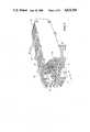
- FIG.1is a perspective view (partly broken away) of a fluid treatment apparatus or filter according to a first embodiment of the invention
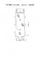
- FIG. 2is a side elevational view of the filter shown in FIG. 1,
- FIG. 3is a plan view of a backing plate of the filter shown in FIG. 1,
- FIG. 4is an exploded view of a filter unit of the filter shown in FIG. 1,
- FIG. 5is a diagrmmatic view of a cross flow filter apparatus constructed in accordance with the principles of the present invention with the filter in a pre-use condition;
- FIG. 6is a schematic view similar to FIG. 7 with the filter in the steady state of feedstock flow
- FIG. 7is an enlarged fragmentry cross-sectional view of a pair of spacer support plates with a pair of compressible membranes disposed therebetween.
- FIG. 8is a partial cross-sectional schematic view of a filter unit showing the gasket seal at the edge of the two membranes with the filter in a pre-use condition
- FIG. 9is a view similar to FIG. 8 with the filter in the steady state of feedstock flow
- FIG. 10is a schematic view showing a blockage forming in the flowpath
- FIG. 11is a schematic view similar to FIG. 10 showing movement of the blockage
- FIG. 12is a cross-sectional side view of a cross-flow filter according to a second embodiment of the invention.
- FIG. 13a partially cutaway perspective view of the filter shown in FIG. 12,
- FIG. 14is a cross-sectional view of a membrane envelope of the filter shown in FIGS. 12 and 13,
- FIG. 15is a cross-sectional schematic view of a further embodiment of the invention.
- FIG. 16is a cross-sectional schematic view of yet another embodiment of the invention.
- the preferred apparatus 10 for altering the concentration of a pre-selected component(s) 11 of a feedstock 12comprises a plurality of barriers 13 adapted to pass said component(s) 11.
- Inlet and manifold means 17 at the right handside of FIG. 1are adapted to direct the feedstock into contact with a first surface of each barrier 13.
- Transfer means 14are adapted to communicate with the opposite surface of each filter membrane 13 to receive the passed component(s) 11, for removal of said passed component(s) 11 from the apparatus 10.
- Outlet and manifold means 15are adapted to remove the treated feedstock 12 from the apparatus 10.
- the boundaries of the flowpaths for the feedstock 12which, in this instance, are as defined by the barriers 13 are adapted to be at least partially enlarged elastically by the passage of feedstock therethrough.
- Limiting means in the form of plates 16are adapted to restrict the extent of elastic enlargement of the flowpaths so as to maintain a laminar flow of said feedstock when the feedstock 12 is flowing through the flowpath at a predetermined operating pressure.
- each filter unitconsists of a first backing plate 16, a first barrier or membrane 13, a gasket 18, a second barrier or membrane 13a and a second backing plate 16a.
- the backing plates 16 and 16ahave a peripheral sealing shoulder 19 which is operative when the filter is assembled together to seal the periphery of the filter bag formed by membranes 13 and 13a.
- only one plate 16could be provided with a shoulder 19 enlarged to engage the other plate 16a in a sealing manner.
- spacer support or backing plates 16, 16a, 16b and 16bare arrange in a stack in spaced relationship to one another with pairs of compressible barriers or membranes 13, 13a; 13b, 13c and 13d, 13e disposed between adjacent plates.
- Each barrieris supported by and spaced from each plate by a plurality of coinical studs 29 formed on each surface of each plate with open volumes 20 formed therebetween.
- Feedstock solution 12is pumped between each pair of barriers which are compressed under the effects of the high transbarrier or transmembrane pressure which is created by the feedstock to form thin channels 22, 23, and 24 splitting the feedstock solution 12 into a concentrate or retentate 25 and a filtrate of permeate 11.
- each pair of opposed spacer support plates 27 and 28is provided with a plurality of conical studs 29 on the surface thereof which serve to support a pair of membranes 30 and 31 disposed between the support plates.
- the barriers employed in this embodimentare compressible and resilient, and, in this instance are multilayered anistropic unltrafiltration membranes. Biofilters, filters or membranes provided with a compressible and resilient backing may also be used.
- each of the membranes 30 and 31is compressed elastically onto the conical studs 29 creating a thin channel or flowpath 34 of variable channel height "h" between the opposed surfaces of the compressible membranes or barriers 30 and 31.
- the feedstock solutionis split into a filtrate or permeate 33 which passes through the membrane and a concentrate or retentate 36.
- each flowpath channel 34As there will be a pressure drop along each flowpath channel 34 from the higher pressure inlet side (left hand side of FIG. 7) to the lower pressure outlet side (righthand side of FIG. 7), the thickness of the flowpaths will not be constant through the length from inlet to outlet. A slight tapering will occur because the higher inlet pressure will compress the inlet zone of the membranes more than the lower outlet pressure will compress the outlet zone of the membranes.
- HThe distance between opposed spacer plates (typically about 250 microns)
- ethe thickness of the membranes or filters
- Hthe distance between opposed spacer plates
- Hthe thickness of the membranes or filters
- the preferred thickness of the flowpaths under steady state flowis that which ensures that the elastic enlargement maintains laminar flow under non-gel polarised conditions for prolong periods of time at high flux.
- itis the channel height or flow path thickness whichf has alters the shear rate for a given velocity of fluid.
- shear rateis inversely proportional to flow path thickness
- a reduction in flow path thicknesswill increase shear rate which will in turn increase flux.
- the flow path thicknessis not a universally chosen parameter, it is preferred that the thickness does not exceed 80 microns or, in some cases 100 microns. In some instances the thickness range extends preferentially from 50 to 100, microns, from 40 to 60 microns and from 10 to 25 microns.
- the preferred compressible, high flux membranes used according to the present inventionare the membranes disclosed in Australian Patent specification No. 505,494. That specification discloses highly-permeable anistropic membranes with graduated porosity, comprising a mixture of depolymerised and polymeric material, and a plurality of adjacent layers with each layer active as a molecular screen and having a precise molecular weight cut-off, wherein the variation of molecular weight cut-off of the adjacent layers from the top to the bottom of the membrane is a continuous function.
- the barrierscould be constituted by a composite of a first portion which is compressible across its transverse dimension and a second portion which is substantially less compressible across its transverse, dimension, and wherein said limiting means is adapted to contact said first portion of said barrier when it restricts the extent of enlargement of the flowpath.
- the gasket means 18is preferably a compressible cellular or closed-cell foam material, such as polyethylene or polypropylene, which under pressure is compressed from about 1 mm to about 15 microns. Under compression, the cells in the foam material rupture forming a plurality of open cell spaces in contact with the surface to be sealed. Each open cell structure acts, in effect, as a small decompression chamber, with a large number of such chambers being present within a relatively small space, acting as an effective seal against loss of pressure in a filtration or ultrafiltration system operating under pressures (i.e.
- transmembrane pressure differentialsof about 100 KPa (or about 15 p.s.i )--as opposed to pressure differentials of less than 10 KPa (or less than 1 p.s.i.) which exist in dialysis apparatus.
- One means of providing for the supply of fluid to be treated under pressure to form a channel between a pair of filtration or ultrafiltration media 13 with the latter adapted to provide a fluid-tight seal with the adjacent plate 16 in the region surrounding the inlet and the outlet openings as described aboveis to ultilise radial fluid distribution discs or buttons 40 (See FIG. 1.) of the type described in the Hagstrom et al U.S. Pat. Nos. 3,837,496 and 3,841,491 between the pair of filtration or ultrafiltration media, coincidental with the inlet and outlet openings.
- buttons 40are detrimental to the compactness of the system, and gives unnecessary flow restriction to the feedstock and there is - under the high operative pressures which exist in apparatus according to the present invention, the necessity to provide an annular compressible sealing gasket (e.g. of polypropylene foam material) on each side of, and concentric with, the button to form a seal under compression between the spacer support plate 16 and the filtration or ultrafiltration media 13.
- annular compressible sealing gaskete.g. of polypropylene foam material
- the active surface 42 of the spacer support plates 16, i.e. wherein passageways are provided for the distribution and collection of the filtrate or permeat 11,may be formed in many various ways according to prior art technique applicable to dialyzing apparatus technology, for example using embossing and stamping techniques.
- 4,051,041can be utilised, especially for the collection of filtrate or permeate from the active surface of the spacer support plate 16 into the permeate outlet part 11 of the apparatus. See also the disclosure of the Alwall et al U.S. Pat. No. 3,411,630 relating to the surface configuration of the spacing members designed to provide a support for the adjacent membrane and to provide a passageway for the dialysing of purifying liquid.
- the present inventionprovides the basis for filtration apparatus having an energy input requirement as small as about 50 and no more than 150 watts/square meter of membrane installed (c.f. an energy requirement of about 1 kW/square meter of membrane installed for classical prior art systems) which means that the present invention provides the basis for a significant saving in energy requirements when compared to known prior art systems.
- Another consequence of use of a preferred form of treatment system according to the present inventionis that the shear rate tends to be extremely high. As a result, the specific flux for a given effluent is increased and it is thus possible to operate the filtration apparatus under non-gel polarized conditions at high flux. This is of importance when it is desirable to maximise molecular selectivity and leads to an easy cleaning of the barriers or membranes.
- An advantage of a treatment system according to a preferred form of the present inventionis that a very high surface area of membrane of filter can be contained within a relatively small volume. Generally speaking, about 10 times more membrane or filter per unit of volume can be contained within a given area than is possible with classical prior art ultrafiltration or cross-flow filtration equipment.
- the apparatusWith membranes incorporated into the apparatus, the apparatus is adapted for cross-flow ultrafiltration.
- the membraneWhen the membrane is replaced by a biofilter or filter the equipment is suitable for cross-flow filtration with two separative effects:
- any given solution where the liquid medium and the particulate matter contained therin are of different densitythen it is possible to obtain a separation in two ways. If the particulate matter is heavier than the liquid, and if the feedstock solution (concentrate) is caused to flow upwards, i.e. in a substantially vertical direction, in the channel, then the particulate matter tends to concentrate in the centre of the channel, with the result that it is possible to remove the permeate without plugging of the filter caused by the particulate matter.
- the tap water feedstockwas recirculated through the cartridge over a 12 hour period while the flux decline was monitored. Initially, the back-pressure was set at 88 kpa. After four hours, the pressure was increased to 100 kpa, the recommended minimum pressure for this application. The cross-flow rate was 186 L/HR. and the temperature was approximately 30 degrees centrigrade. At an inlet pressure of 88 kpa, the stabilized flux was 64 L/SP.M.HR. The pressure drop across the cartridge was 20 kpa. The stabilized flux at 100 kpa was 74.3 L/SQ.M.HR., and showed no decline over the last 8 hours of the experiment.
- the flux versus pressure relationship for the cartridgeindicated that the experiment was carried out in a pre-gel polarized condition.
- the total dry solids content of 0.19 G/L for the feedstock and 0.08 G/L for the permeategave a total solids rejection of 0.19 G/L for the feedstock and 0.08 G/L for the permeate gave a total solids rejection of 60 O/O for this experiment.
- the above datashows the low power consumption per unit of purified water, as well as the low power consumption per unit area of membrane.
- a further aspect of the inventionrelates to the adaption of the apparatus for electrodialysis.
- the particular configuration of the filtration modules of a preferred form of the present inventionallows for the incorporation into the two end plate manifolds of a stacked assembly of plates of two metallic plates as electrodes to establish an electric field.
- the filtration modulewould be adapted to operate as an electrodialysis unit.
- the unitwould be adapted to operate as a reverse electrodialysis or transport depletion unit.
- FIGS. 12 to 14A second embodiment of the invention is shown in FIGS. 12 to 14.
- the apparatusincludes a main body portion 60 having an inlet thereto 61 and an outlet therefrom 62.
- a plurality of membrane envelopes 63Within the main body portion 60 is a plurality of membrane envelopes 63.
- Each envelope 63includes a first membrane or barrier 64 and an overlying second membrane or barrier 65 which are held in spaced relation by grid 66.
- the periphery of the overlying barriers 64 65is sealed together as shown in FIG. 14 except for one side thereof which projects into manifold 67 as shown in FIG. 13.
- Manifold 67constitutes the transfer means for the apparatus and the space between each of the envelopes 63 is closed by a sealing material such as aryldite as identified by numeral 68 in FIG. 13.
- FIG. 15A further embodiment of the invention is shown in FIG. 15 wherein the membranes or barriers 70 and 71 have aligned and co-operating projections 74 and 75 which define flowpaths 76.
- the flowpath between the barriers 70 and 71is divided into a plurality of parallel flowpaths each of which is restricted in its elastic enlargement by the backing plate 72 and 73.
- FIG. 16Yet another embodiment of the invention is shown in FIG. 16 wherein envelopes 80 and 81 are spirally wound within each other.
- Each envelope 80 and 81is substantially similar to the envelope 63 shown in FIGS. 12 to 14.
- Each envelope 80 and 81has outlet means 82 and the assembly of envelopes is adapted to be positioned within a housing having an inlet thereto and an outlet therefrom.
- the inventionis not limited to cross flow filtration or retention.
- the preferred form of the invention described in relation to FIGS. 1 to 7could be used to introduce a preferred species into the feedstock by entry through the transfer port and the barrier(s) in the reverse direction to that described above.
- One such applicationconcerns the introduction of oxygen (the preferred specie) into blood (the feedstock).
- the barriersare so chosen that the oxygen may readily flow thereacross but all components of the blood are retained in the flowpaths.
Landscapes
- Chemical & Material Sciences (AREA)
- Chemical Kinetics & Catalysis (AREA)
- Engineering & Computer Science (AREA)
- Water Supply & Treatment (AREA)
- Separation Using Semi-Permeable Membranes (AREA)
- Physical Or Chemical Processes And Apparatus (AREA)
Abstract
Description
Jα(γ/L).sup.0.33 α(U.sub.B).sup.0.33 (h.sub.c).sup.-0.33 (L).sup.-0.33
γα(ν/hc)
Claims (8)
Applications Claiming Priority (2)
| Application Number | Priority Date | Filing Date | Title |
|---|---|---|---|
| AUPE5372 | 1980-09-03 | ||
| AUPE537280 | 1980-09-03 |
Related Parent Applications (1)
| Application Number | Title | Priority Date | Filing Date |
|---|---|---|---|
| US06375139Continuation | 1982-04-28 |
Publications (1)
| Publication Number | Publication Date |
|---|---|
| US4624784Atrue US4624784A (en) | 1986-11-25 |
Family
ID=3768674
Family Applications (1)
| Application Number | Title | Priority Date | Filing Date |
|---|---|---|---|
| US06/679,613Expired - Fee RelatedUS4624784A (en) | 1980-09-03 | 1981-09-03 | Apparatus including a flow path formed by membrane compression |
Country Status (9)
| Country | Link |
|---|---|
| US (1) | US4624784A (en) |
| EP (2) | EP0059205B1 (en) |
| JP (1) | JPH0361483B2 (en) |
| AU (1) | AU540018B2 (en) |
| CA (1) | CA1182761A (en) |
| DK (1) | DK162074C (en) |
| GB (1) | GB2093369B (en) |
| NZ (1) | NZ198268A (en) |
| WO (1) | WO1982000775A1 (en) |
Cited By (49)
| Publication number | Priority date | Publication date | Assignee | Title |
|---|---|---|---|---|
| US4867876A (en)* | 1987-10-02 | 1989-09-19 | Kopf Henry B | Filter plate, filter plate element, and filter comprising same |
| WO1990001981A1 (en)* | 1988-08-22 | 1990-03-08 | Kopf Henry B | Filter plate, filter plate element and filter comprising same |
| US4956085A (en)* | 1987-10-02 | 1990-09-11 | Kopf Henry B | Filter plate, filter plate element and filter comprising same |
| US5037562A (en)* | 1984-08-22 | 1991-08-06 | Tarves Robert J Jun | Oil/liquid dynamic separation rotating disk filter system with barrier layer formation |
| US5049268A (en)* | 1987-10-02 | 1991-09-17 | Kopf Henry B | Filter plate, filter plate element, and filter comprising same |
| US5096582A (en)* | 1990-09-25 | 1992-03-17 | Millipore Corporation | Tangential flow filtration apparatus |
| USD324720S (en) | 1989-06-09 | 1992-03-17 | Kopf Henry B | Filter plate |
| USD325070S (en) | 1989-06-09 | 1992-03-31 | Kopf Henry B | Filter sheet |
| USD327313S (en) | 1989-09-01 | 1992-06-23 | Kopf Henry B | Filter plate |
| USD328789S (en) | 1990-03-01 | 1992-08-18 | Kopf Henry B | Filter sheet support element |
| US5160433A (en)* | 1986-06-16 | 1992-11-03 | Niesen Lawrence J | Laboratory scale ultrafiltration apparatus |
| US5232589A (en)* | 1987-10-02 | 1993-08-03 | Kopf Henry B | Filter element and support |
| US5282101A (en)* | 1990-05-03 | 1994-01-25 | Seagate Technology, Inc. | Disc drive gasket and method of forming same |
| US5342517A (en)* | 1987-10-02 | 1994-08-30 | Kopf Henry B | Filtration cassette article, and filter comprising same |
| USD357059S (en) | 1994-03-01 | 1995-04-04 | Kopf Henry B | Flat sheet membrane mass transfer module |
| US5575910A (en)* | 1994-09-14 | 1996-11-19 | Sartorius Ag | Membrane adsorber filter module |
| US5593580A (en)* | 1986-11-26 | 1997-01-14 | Kopf; Henry B. | Filtration cassette article, and filter comprising same |
| US5755962A (en)* | 1996-11-26 | 1998-05-26 | Isp Investments Inc. | Filter bag and process of manufacture |
| US5868930A (en)* | 1986-11-26 | 1999-02-09 | Kopf; Henry B. | Filtration cassette article and filter comprising same |
| USD406882S (en)* | 1996-07-11 | 1999-03-16 | Glegg Water Conditioning, Inc. | Spacer-gasket |
| US20050092666A1 (en)* | 2003-11-04 | 2005-05-05 | Wilson John R. | Dialysis cartridge |
| US20050150768A1 (en)* | 2002-02-21 | 2005-07-14 | Eet Corporation | Multi-path split cell spacer and electrodialysis stack design |
| US20060070456A1 (en)* | 2004-09-08 | 2006-04-06 | Douglas Stephen L | Bed having a patient position monitoring system |
| US20070056894A1 (en)* | 2005-09-09 | 2007-03-15 | Tangenx Technology Corporation | Laminated cassette device and methods for making same |
| US20070125722A1 (en)* | 2003-05-21 | 2007-06-07 | Olivier De Biran | Device for the separation of a fluid into at least two fractions, using a plurality of membrane filters, and use thereof |
| US7316780B1 (en) | 1999-01-29 | 2008-01-08 | Pall Corporation | Range separation devices and processes |
| US20080029451A1 (en)* | 2006-07-28 | 2008-02-07 | Millipore Corporation | Manifold adaptor plate for filtration apparatus |
| US20080093298A1 (en)* | 2004-10-06 | 2008-04-24 | Browning David M | Mecs Diayzer |
| US20080257819A1 (en)* | 2007-04-18 | 2008-10-23 | Tarves Robert J | Dual walled dynamic phase separator |
| US20090008235A1 (en)* | 2007-07-02 | 2009-01-08 | I3 Nanotec Llc. | Membrane-based hybrid process for separation of mixtures of organics, solids, and water |
| US20090056020A1 (en)* | 2007-08-30 | 2009-03-05 | Jean-Luc Caminade | Pressure detection and measurement sensor incorporating at least one resistive force-detector cell |
| US20090255877A1 (en)* | 2008-04-11 | 2009-10-15 | Pall Corporation | Fluid treatment arrangements and methods |
| US20100018924A1 (en)* | 2008-07-28 | 2010-01-28 | Pall Corporation | Fluid treatment arrangements and methods |
| US20100282663A1 (en)* | 2007-10-03 | 2010-11-11 | Hunt Stephen G | Filtration cartridge formed of stacked plates |
| US20100288690A1 (en)* | 2007-10-03 | 2010-11-18 | Millipore Corporation | Stacked plates filtration cartridge |
| US20100308846A1 (en)* | 2009-06-05 | 2010-12-09 | Gilles Camus | Pressure sensor comprising a capacitive cell and support device comprising said sensor |
| US8137554B2 (en) | 2004-10-06 | 2012-03-20 | State Of Oregon Acting By And Through The State Board Of Higher Education On Behalf Of Oregon State University | Microfluidic devices, particularly filtration devices comprising polymeric membranes, and method for their manufacture and use |
| WO2012044810A3 (en)* | 2010-09-30 | 2012-07-05 | Baker Hughes Incorporated | Anisotropic filtration media and method of making |
| US8524086B2 (en) | 2010-06-07 | 2013-09-03 | State Of Oregon Acting By And Through The State Board Of Higher Education On Behalf Of Oregon State University | Fluid purification system |
| US8580161B2 (en) | 2010-05-04 | 2013-11-12 | State Of Oregon Acting By And Through The State Board Of Higher Education On Behalf Of Oregon State University | Fluidic devices comprising photocontrollable units |
| US9328969B2 (en) | 2011-10-07 | 2016-05-03 | Outset Medical, Inc. | Heat exchange fluid purification for dialysis system |
| US9402945B2 (en) | 2014-04-29 | 2016-08-02 | Outset Medical, Inc. | Dialysis system and methods |
| US9545469B2 (en) | 2009-12-05 | 2017-01-17 | Outset Medical, Inc. | Dialysis system with ultrafiltration control |
| US10029280B2 (en)* | 2016-12-14 | 2018-07-24 | Metal Industries Research & Development Centre | Sieve for microparticles |
| US10987631B2 (en) | 2018-04-17 | 2021-04-27 | Smartflow Technologies, Inc. | Filter cassette article, and filter comprising same |
| EP3837035A4 (en)* | 2018-08-16 | 2022-05-18 | EMD Millipore Corporation | Closed bioprocessing device |
| US11534537B2 (en) | 2016-08-19 | 2022-12-27 | Outset Medical, Inc. | Peritoneal dialysis system and methods |
| US12201762B2 (en) | 2018-08-23 | 2025-01-21 | Outset Medical, Inc. | Dialysis system and methods |
| US12390565B2 (en) | 2019-04-30 | 2025-08-19 | Outset Medical, Inc. | Dialysis systems and methods |
Families Citing this family (8)
| Publication number | Priority date | Publication date | Assignee | Title |
|---|---|---|---|---|
| NL8202703A (en)* | 1981-10-01 | 1983-05-02 | Cobe Lab | METHOD AND APPARATUS FOR SEPARATING LIQUID FILTRATES FREE FROM PARTICLES LARGER THAN A PRE-DEFINED SIZE, FROM LIQUID MIXTURES OF THE PARTICLES |
| FR2576805B1 (en)* | 1985-02-01 | 1989-08-25 | Lyonnaise Eaux | TANGENTIAL FILTRATION APPARATUS |
| ATE100935T1 (en)* | 1986-01-27 | 1994-02-15 | Univ Utah | PROCESS FOR SEPARATION OF A FLOW USING FINE CHANNELS AND PLANT FOR FRACTIONATION OF SOLID PARTICLES. |
| US4997565A (en)* | 1986-06-16 | 1991-03-05 | Niesen Lawrence J | Laboratory scale ultrafiltration apparatus |
| US4801381A (en)* | 1986-06-16 | 1989-01-31 | Niesen Lawrence J | Ultrafiltration apparatus |
| FR2662114B1 (en)* | 1990-05-15 | 1994-04-29 | Eurodia Sa | METHOD FOR MANUFACTURING A SEPARATOR FRAME FOR STACKING IN AN EXCHANGE DEVICE. |
| DE102004007848A1 (en)* | 2004-02-17 | 2005-09-01 | Bayer Technology Services Gmbh | Apparatus and method for membrane electrophoresis and electrofiltration |
| AT504206B8 (en) | 2006-12-19 | 2008-09-15 | Gruene Bioraffinerie At Gmbh | METHOD FOR TREATING A STAFF CURRENT |
Citations (16)
| Publication number | Priority date | Publication date | Assignee | Title |
|---|---|---|---|---|
| DE918810C (en)* | 1937-12-08 | 1954-10-04 | Gerrit Willem Van Barneveld Ko | Method and device for continuous dialysis of liquids containing colloidal substances |
| US3501010A (en)* | 1967-01-12 | 1970-03-17 | Eastman Kodak Co | Dialyzing apparatus and method of making the same |
| US3556302A (en)* | 1969-01-06 | 1971-01-19 | Amicon Corp | Filtration apparatus having flow distributor |
| US3612281A (en)* | 1968-03-11 | 1971-10-12 | Baxter Laboratories Inc | Parallel membranous layer type fluid diffusion cell |
| US3730350A (en)* | 1968-12-07 | 1973-05-01 | Baxter Laboratories Inc | Plate dialyzer |
| US3788482A (en)* | 1972-03-10 | 1974-01-29 | Atomic Energy Commission | Folded membrane dialyzer |
| GB1355671A (en)* | 1970-07-02 | 1974-06-05 | Gen Electric | Blood component exchange device |
| DE2430488A1 (en)* | 1973-06-28 | 1975-01-16 | Osmomed Dialysegeraete Gmbh & | Artificial kidney with cylindrical container - has expanded synthetic material container wall, impermeable inner sheet |
| US3864248A (en)* | 1971-04-13 | 1975-02-04 | Rhone Poulenc Sa | Pressure modulator for an artificial blood circuit |
| US3907687A (en)* | 1968-12-07 | 1975-09-23 | Baxter Laboratories Inc | Plate dialyzer |
| US3910841A (en)* | 1974-04-02 | 1975-10-07 | William G Esmond | Stacked exchange device |
| GB1417564A (en)* | 1972-11-14 | 1975-12-10 | Frings Gmbh | Process and apparatus for filtration of liquids that contain microorganisms macromolecules or finely divided solid matter |
| US3943057A (en)* | 1973-07-11 | 1976-03-09 | Rhone-Poulenc, S.A. | Membrane support-plates and fluid separating apparatus in which they are present |
| US4024059A (en)* | 1974-04-23 | 1977-05-17 | Rhone-Poulenc Industries | Artificial kidney |
| US4160791A (en)* | 1974-03-26 | 1979-07-10 | The United States Of America As Represented By The Secretary Of The Department Of Health, Education And Welfare | Polycarbonate membranes and production thereof |
| US4234428A (en)* | 1978-10-12 | 1980-11-18 | Baxter Travenol Laboratories, Inc. | Dual membrane mass transfer device |
Family Cites Families (3)
| Publication number | Priority date | Publication date | Assignee | Title |
|---|---|---|---|---|
| SE378358B (en)* | 1973-12-10 | 1975-09-01 | Johansson P J | |
| SE407900B (en)* | 1976-06-11 | 1979-04-30 | Gambro Ab | DEVICE FOR DIFFUSION OF THE SUBJECT BETWEEN TWO FLUIDES VIA SEMIPERMEABLE MEMBRANE |
| FR2400380B1 (en)* | 1978-12-21 | 1982-04-09 | Rhone Poulenc Ind |
- 1981
- 1981-09-03CACA000385112Apatent/CA1182761A/ennot_activeExpired
- 1981-09-03NZNZ198268Apatent/NZ198268A/enunknown
- 1981-09-03WOPCT/AU1981/000126patent/WO1982000775A1/enactiveIP Right Grant
- 1981-09-03EPEP81902464Apatent/EP0059205B1/ennot_activeExpired
- 1981-09-03JPJP56502910Apatent/JPH0361483B2/janot_activeExpired
- 1981-09-03USUS06/679,613patent/US4624784A/ennot_activeExpired - Fee Related
- 1981-09-03GBGB8210097Apatent/GB2093369B/ennot_activeExpired
- 1981-09-03AUAU75377/81Apatent/AU540018B2/ennot_activeCeased
- 1981-09-03EPEP81304032Apatent/EP0049055B1/ennot_activeExpired
- 1982
- 1982-04-30DKDK195482Apatent/DK162074C/ennot_activeIP Right Cessation
Patent Citations (16)
| Publication number | Priority date | Publication date | Assignee | Title |
|---|---|---|---|---|
| DE918810C (en)* | 1937-12-08 | 1954-10-04 | Gerrit Willem Van Barneveld Ko | Method and device for continuous dialysis of liquids containing colloidal substances |
| US3501010A (en)* | 1967-01-12 | 1970-03-17 | Eastman Kodak Co | Dialyzing apparatus and method of making the same |
| US3612281A (en)* | 1968-03-11 | 1971-10-12 | Baxter Laboratories Inc | Parallel membranous layer type fluid diffusion cell |
| US3730350A (en)* | 1968-12-07 | 1973-05-01 | Baxter Laboratories Inc | Plate dialyzer |
| US3907687A (en)* | 1968-12-07 | 1975-09-23 | Baxter Laboratories Inc | Plate dialyzer |
| US3556302A (en)* | 1969-01-06 | 1971-01-19 | Amicon Corp | Filtration apparatus having flow distributor |
| GB1355671A (en)* | 1970-07-02 | 1974-06-05 | Gen Electric | Blood component exchange device |
| US3864248A (en)* | 1971-04-13 | 1975-02-04 | Rhone Poulenc Sa | Pressure modulator for an artificial blood circuit |
| US3788482A (en)* | 1972-03-10 | 1974-01-29 | Atomic Energy Commission | Folded membrane dialyzer |
| GB1417564A (en)* | 1972-11-14 | 1975-12-10 | Frings Gmbh | Process and apparatus for filtration of liquids that contain microorganisms macromolecules or finely divided solid matter |
| DE2430488A1 (en)* | 1973-06-28 | 1975-01-16 | Osmomed Dialysegeraete Gmbh & | Artificial kidney with cylindrical container - has expanded synthetic material container wall, impermeable inner sheet |
| US3943057A (en)* | 1973-07-11 | 1976-03-09 | Rhone-Poulenc, S.A. | Membrane support-plates and fluid separating apparatus in which they are present |
| US4160791A (en)* | 1974-03-26 | 1979-07-10 | The United States Of America As Represented By The Secretary Of The Department Of Health, Education And Welfare | Polycarbonate membranes and production thereof |
| US3910841A (en)* | 1974-04-02 | 1975-10-07 | William G Esmond | Stacked exchange device |
| US4024059A (en)* | 1974-04-23 | 1977-05-17 | Rhone-Poulenc Industries | Artificial kidney |
| US4234428A (en)* | 1978-10-12 | 1980-11-18 | Baxter Travenol Laboratories, Inc. | Dual membrane mass transfer device |
Non-Patent Citations (4)
| Title |
|---|
| Lacey, R. E. et al, Industrial Processing with Membranes, Wiley Interscience, N.Y., 1972, p. 211.* |
| Lacey, R. E. et al, Industrial Processing with Membranes, Wiley-Interscience, N.Y., 1972, p. 211. |
| Nose, Y., "Critical Review of Renal Prostheses", CRC, Critical Reviews in Bioengineering, Oct. 1972, pp. 255-271. |
| Nose, Y., Critical Review of Renal Prostheses , CRC, Critical Reviews in Bioengineering, Oct. 1972, pp. 255 271.* |
Cited By (80)
| Publication number | Priority date | Publication date | Assignee | Title |
|---|---|---|---|---|
| US5037562A (en)* | 1984-08-22 | 1991-08-06 | Tarves Robert J Jun | Oil/liquid dynamic separation rotating disk filter system with barrier layer formation |
| US5160433A (en)* | 1986-06-16 | 1992-11-03 | Niesen Lawrence J | Laboratory scale ultrafiltration apparatus |
| US5868930A (en)* | 1986-11-26 | 1999-02-09 | Kopf; Henry B. | Filtration cassette article and filter comprising same |
| US5593580A (en)* | 1986-11-26 | 1997-01-14 | Kopf; Henry B. | Filtration cassette article, and filter comprising same |
| US4956085A (en)* | 1987-10-02 | 1990-09-11 | Kopf Henry B | Filter plate, filter plate element and filter comprising same |
| US5342517A (en)* | 1987-10-02 | 1994-08-30 | Kopf Henry B | Filtration cassette article, and filter comprising same |
| US5049268A (en)* | 1987-10-02 | 1991-09-17 | Kopf Henry B | Filter plate, filter plate element, and filter comprising same |
| US4867876A (en)* | 1987-10-02 | 1989-09-19 | Kopf Henry B | Filter plate, filter plate element, and filter comprising same |
| US5232589A (en)* | 1987-10-02 | 1993-08-03 | Kopf Henry B | Filter element and support |
| US5034124A (en)* | 1988-08-22 | 1991-07-23 | Kopf Henry B | Filter plate, filter plate element, and filter comprising same |
| WO1990001981A1 (en)* | 1988-08-22 | 1990-03-08 | Kopf Henry B | Filter plate, filter plate element and filter comprising same |
| USD325070S (en) | 1989-06-09 | 1992-03-31 | Kopf Henry B | Filter sheet |
| USD324720S (en) | 1989-06-09 | 1992-03-17 | Kopf Henry B | Filter plate |
| USD327313S (en) | 1989-09-01 | 1992-06-23 | Kopf Henry B | Filter plate |
| USD328789S (en) | 1990-03-01 | 1992-08-18 | Kopf Henry B | Filter sheet support element |
| US5282101A (en)* | 1990-05-03 | 1994-01-25 | Seagate Technology, Inc. | Disc drive gasket and method of forming same |
| US5096582A (en)* | 1990-09-25 | 1992-03-17 | Millipore Corporation | Tangential flow filtration apparatus |
| USD357059S (en) | 1994-03-01 | 1995-04-04 | Kopf Henry B | Flat sheet membrane mass transfer module |
| US5575910A (en)* | 1994-09-14 | 1996-11-19 | Sartorius Ag | Membrane adsorber filter module |
| USD406882S (en)* | 1996-07-11 | 1999-03-16 | Glegg Water Conditioning, Inc. | Spacer-gasket |
| US5755962A (en)* | 1996-11-26 | 1998-05-26 | Isp Investments Inc. | Filter bag and process of manufacture |
| US7316780B1 (en) | 1999-01-29 | 2008-01-08 | Pall Corporation | Range separation devices and processes |
| US20050150768A1 (en)* | 2002-02-21 | 2005-07-14 | Eet Corporation | Multi-path split cell spacer and electrodialysis stack design |
| US7138045B2 (en) | 2002-02-21 | 2006-11-21 | Alois Sferrazza | Multi-path split cell spacer and electrodialysis stack design |
| US7569144B2 (en)* | 2003-05-21 | 2009-08-04 | Applexion | Device for the separation of a fluid into at least two fractions, using a plurality of membrane filters, and use thereof |
| US20070125722A1 (en)* | 2003-05-21 | 2007-06-07 | Olivier De Biran | Device for the separation of a fluid into at least two fractions, using a plurality of membrane filters, and use thereof |
| US20050092666A1 (en)* | 2003-11-04 | 2005-05-05 | Wilson John R. | Dialysis cartridge |
| US7464605B2 (en)* | 2004-09-08 | 2008-12-16 | Hill-Rom Services, Inc. | Bed having a patient position monitoring system |
| US20060070456A1 (en)* | 2004-09-08 | 2006-04-06 | Douglas Stephen L | Bed having a patient position monitoring system |
| US20080093298A1 (en)* | 2004-10-06 | 2008-04-24 | Browning David M | Mecs Diayzer |
| US8419945B2 (en) | 2004-10-06 | 2013-04-16 | State Of Oregon Acting By And Through The State Board Of Higher Education On Behalf Of Oregon State University | MECS dialyzer method |
| US8137554B2 (en) | 2004-10-06 | 2012-03-20 | State Of Oregon Acting By And Through The State Board Of Higher Education On Behalf Of Oregon State University | Microfluidic devices, particularly filtration devices comprising polymeric membranes, and method for their manufacture and use |
| US8128822B2 (en) | 2004-10-06 | 2012-03-06 | State Of Oregon Acting By And Through The State Board Of Higher Education On Behalf Of Oregon State University | MECS dialyzer |
| US8273245B2 (en) | 2004-10-06 | 2012-09-25 | State Of Oregon Acting By And Through The State Board Of Higher Education On Behalf Of Oregon State University | Microfluidic devices, particularly filtration devices comprising polymeric membranes, and methods for their manufacture and use |
| US8007670B2 (en)* | 2005-09-09 | 2011-08-30 | Tangenx Technology Corporation | Laminated cassette device and methods for making same |
| US20070056894A1 (en)* | 2005-09-09 | 2007-03-15 | Tangenx Technology Corporation | Laminated cassette device and methods for making same |
| US20080029451A1 (en)* | 2006-07-28 | 2008-02-07 | Millipore Corporation | Manifold adaptor plate for filtration apparatus |
| US7959805B2 (en)* | 2006-07-28 | 2011-06-14 | Millipore Corporation | Manifold adaptor plate for filtration apparatus |
| US20080257819A1 (en)* | 2007-04-18 | 2008-10-23 | Tarves Robert J | Dual walled dynamic phase separator |
| US8070965B2 (en) | 2007-04-18 | 2011-12-06 | Tarves Robert J Jun | Dual walled dynamic phase separator |
| US8425734B2 (en)* | 2007-07-02 | 2013-04-23 | I3 Nanotec Llc | Membrane-based hybrid process for separation of mixtures of organics, solids, and water |
| US20090008235A1 (en)* | 2007-07-02 | 2009-01-08 | I3 Nanotec Llc. | Membrane-based hybrid process for separation of mixtures of organics, solids, and water |
| US7752926B2 (en) | 2007-08-30 | 2010-07-13 | Hill-Rom Industries, SA | Pressure detection and measurement sensor incorporating at least one resistive force-detector cell |
| US20090056020A1 (en)* | 2007-08-30 | 2009-03-05 | Jean-Luc Caminade | Pressure detection and measurement sensor incorporating at least one resistive force-detector cell |
| US20100288690A1 (en)* | 2007-10-03 | 2010-11-18 | Millipore Corporation | Stacked plates filtration cartridge |
| US8936724B2 (en)* | 2007-10-03 | 2015-01-20 | Emd Millipore Corporation | Filtration cartridge formed of stacked plates |
| US20100282663A1 (en)* | 2007-10-03 | 2010-11-11 | Hunt Stephen G | Filtration cartridge formed of stacked plates |
| US8911624B2 (en)* | 2007-10-03 | 2014-12-16 | Emd Millipore Corporation | Stacked plates filtration cartridge |
| US8043512B2 (en) | 2008-04-11 | 2011-10-25 | Pall Corporation | Fluid treatment arrangements and methods |
| US20090255877A1 (en)* | 2008-04-11 | 2009-10-15 | Pall Corporation | Fluid treatment arrangements and methods |
| US20100018924A1 (en)* | 2008-07-28 | 2010-01-28 | Pall Corporation | Fluid treatment arrangements and methods |
| US8048315B2 (en) | 2008-07-28 | 2011-11-01 | Pall Corporation | Fluid treatment arrangements and methods |
| US8598893B2 (en) | 2009-06-05 | 2013-12-03 | Hill-Rom Industries Sa | Pressure sensor comprising a capacitive cell and support device comprising said sensor |
| US20100308846A1 (en)* | 2009-06-05 | 2010-12-09 | Gilles Camus | Pressure sensor comprising a capacitive cell and support device comprising said sensor |
| US9545469B2 (en) | 2009-12-05 | 2017-01-17 | Outset Medical, Inc. | Dialysis system with ultrafiltration control |
| US8580161B2 (en) | 2010-05-04 | 2013-11-12 | State Of Oregon Acting By And Through The State Board Of Higher Education On Behalf Of Oregon State University | Fluidic devices comprising photocontrollable units |
| US8524086B2 (en) | 2010-06-07 | 2013-09-03 | State Of Oregon Acting By And Through The State Board Of Higher Education On Behalf Of Oregon State University | Fluid purification system |
| US9138687B2 (en) | 2010-06-07 | 2015-09-22 | Oregon State University | Fluid purification system |
| US10105476B2 (en) | 2010-06-07 | 2018-10-23 | Oregon State University | Fluid purification system |
| US11724013B2 (en) | 2010-06-07 | 2023-08-15 | Outset Medical, Inc. | Fluid purification system |
| GB2497214A (en)* | 2010-09-30 | 2013-06-05 | Baker Hughes Inc | Anisotropic filtration media and method of making |
| CN103096993A (en)* | 2010-09-30 | 2013-05-08 | 贝克休斯公司 | Anisotropic filtration media and method of making |
| WO2012044810A3 (en)* | 2010-09-30 | 2012-07-05 | Baker Hughes Incorporated | Anisotropic filtration media and method of making |
| US9238316B2 (en) | 2010-09-30 | 2016-01-19 | Baker Hughes Incorporated | Method of making an anisotropic filtration media |
| GB2497214B (en)* | 2010-09-30 | 2018-03-21 | Baker Hughes Inc | Anisotropic filtration media and method of making |
| US8517184B2 (en) | 2010-09-30 | 2013-08-27 | Baker Hughes Incorporated | Anisotropic filtration media |
| US9328969B2 (en) | 2011-10-07 | 2016-05-03 | Outset Medical, Inc. | Heat exchange fluid purification for dialysis system |
| US9402945B2 (en) | 2014-04-29 | 2016-08-02 | Outset Medical, Inc. | Dialysis system and methods |
| US9579440B2 (en) | 2014-04-29 | 2017-02-28 | Outset Medical, Inc. | Dialysis system and methods |
| US11305040B2 (en) | 2014-04-29 | 2022-04-19 | Outset Medical, Inc. | Dialysis system and methods |
| US9504777B2 (en) | 2014-04-29 | 2016-11-29 | Outset Medical, Inc. | Dialysis system and methods |
| US11534537B2 (en) | 2016-08-19 | 2022-12-27 | Outset Medical, Inc. | Peritoneal dialysis system and methods |
| US11951241B2 (en) | 2016-08-19 | 2024-04-09 | Outset Medical, Inc. | Peritoneal dialysis system and methods |
| US10029280B2 (en)* | 2016-12-14 | 2018-07-24 | Metal Industries Research & Development Centre | Sieve for microparticles |
| US10987631B2 (en) | 2018-04-17 | 2021-04-27 | Smartflow Technologies, Inc. | Filter cassette article, and filter comprising same |
| US11654397B2 (en) | 2018-04-17 | 2023-05-23 | Smartflow Technologies, Inc. | Filter cassette article, and filter comprising same |
| EP3837035A4 (en)* | 2018-08-16 | 2022-05-18 | EMD Millipore Corporation | Closed bioprocessing device |
| US12172108B2 (en) | 2018-08-16 | 2024-12-24 | Emd Millipore Corporation | Closed bioprocessing device |
| US12201762B2 (en) | 2018-08-23 | 2025-01-21 | Outset Medical, Inc. | Dialysis system and methods |
| US12390565B2 (en) | 2019-04-30 | 2025-08-19 | Outset Medical, Inc. | Dialysis systems and methods |
Also Published As
| Publication number | Publication date |
|---|---|
| EP0049055B1 (en) | 1986-06-18 |
| EP0059205B1 (en) | 1986-12-30 |
| NZ198268A (en) | 1984-03-30 |
| EP0059205A4 (en) | 1982-11-16 |
| DK162074C (en) | 1992-02-17 |
| AU7537781A (en) | 1982-03-31 |
| JPH0361483B2 (en) | 1991-09-20 |
| GB2093369A (en) | 1982-09-02 |
| GB2093369B (en) | 1984-07-18 |
| EP0049055A1 (en) | 1982-04-07 |
| WO1982000775A1 (en) | 1982-03-18 |
| DK162074B (en) | 1991-09-16 |
| AU540018B2 (en) | 1984-10-25 |
| EP0059205A1 (en) | 1982-09-08 |
| JPS57501364A (en) | 1982-08-05 |
| DK195482A (en) | 1982-04-30 |
| CA1182761A (en) | 1985-02-19 |
Similar Documents
| Publication | Publication Date | Title |
|---|---|---|
| US4624784A (en) | Apparatus including a flow path formed by membrane compression | |
| EP0137877B1 (en) | Series ultrafiltration with pressurized permeate and apparatus therefor | |
| US3872014A (en) | Membrane separation apparatus | |
| CA1321148C (en) | Spirally wrapped reverse osmosis membrane cell | |
| US11565215B2 (en) | Permeate channel alterations for counter current filtration for use in cross-flow filtration modules useful in osmotic systems | |
| US5096582A (en) | Tangential flow filtration apparatus | |
| US4867876A (en) | Filter plate, filter plate element, and filter comprising same | |
| US3556302A (en) | Filtration apparatus having flow distributor | |
| US4735718A (en) | Multilayer membrane separator | |
| US5458774A (en) | Corrugated spiral membrane module | |
| US4244820A (en) | Fluid purification system | |
| CA2161055A1 (en) | Device for Filtering and Separating Particularly of Biologically Organic Flow Media with Filter Elements of the Type of Membrane Cushions | |
| US3367505A (en) | Semipermeable membrane backing and support medium | |
| US5258122A (en) | Cross-flow filter device with pressure-balancing feature | |
| US4340475A (en) | Membrane separation cell | |
| JP2002292249A (en) | Filtration separation apparatus for filtering and separating fluid medium based on ultrafiltration | |
| KR880000173B1 (en) | Fluid treatment apparatus | |
| JP2004524140A5 (en) | ||
| RU2033188C1 (en) | Multichamber membrane filter | |
| NO157485B (en) | DEVICE TO CHANGE THE CONCENTRATION OF ONE OR MORE PRESELECTED COMPONENTS IN A SUPPLY MATERIAL. | |
| JPH04190834A (en) | Cross-flow type filter | |
| Agrawal et al. | Application of membrane‐based preferential transport to whole broth processing | |
| Piskin | Synthetic polymeric membranes: separation via membranes | |
| JPH04118032A (en) | Jet flow type filter | |
| JPS63158101A (en) | Filter plate for flat membrane type separator |
Legal Events
| Date | Code | Title | Description |
|---|---|---|---|
| AS | Assignment | Owner name:TRAVENOL LABORATORIES PTY. LIMITED, OAKES ROAD, OL Free format text:ASSIGNMENT OF ASSIGNORS INTEREST.;ASSIGNOR:MEMTEC LABORATORIES PTY LIMITED ( IN LIQUIDATION );REEL/FRAME:004592/0099 Effective date:19860724 | |
| AS | Assignment | Owner name:MEMTEC LIMITED, 60 MACQUARIE STREET, PARRAMATTA, N Free format text:ASSIGNMENT OF ASSIGNORS INTEREST.;ASSIGNOR:TRAVENOL LABORATORIES PTY. LIMITED;REEL/FRAME:004601/0993 Effective date:19860805 Owner name:MEMTEC LIMITED, A CORP. OF AUSTRALIA, AUSTRIA Free format text:ASSIGNMENT OF ASSIGNORS INTEREST;ASSIGNOR:TRAVENOL LABORATORIES PTY. LIMITED;REEL/FRAME:004601/0993 Effective date:19860805 | |
| FEPP | Fee payment procedure | Free format text:PAT HLDR NO LONGER CLAIMS SMALL ENT STAT AS INDIV INVENTOR (ORIGINAL EVENT CODE: LSM1); ENTITY STATUS OF PATENT OWNER: LARGE ENTITY | |
| FPAY | Fee payment | Year of fee payment:4 | |
| FEPP | Fee payment procedure | Free format text:PAYOR NUMBER ASSIGNED (ORIGINAL EVENT CODE: ASPN); ENTITY STATUS OF PATENT OWNER: LARGE ENTITY | |
| FPAY | Fee payment | Year of fee payment:8 | |
| REMI | Maintenance fee reminder mailed | ||
| SULP | Surcharge for late payment | ||
| REMI | Maintenance fee reminder mailed | ||
| LAPS | Lapse for failure to pay maintenance fees | ||
| FP | Lapsed due to failure to pay maintenance fee | Effective date:19981125 | |
| STCH | Information on status: patent discontinuation | Free format text:PATENT EXPIRED DUE TO NONPAYMENT OF MAINTENANCE FEES UNDER 37 CFR 1.362 |