US4624771A - Fluid catalytic cracking of vacuum residuum oil - Google Patents
Fluid catalytic cracking of vacuum residuum oilDownload PDFInfo
- Publication number
- US4624771A US4624771AUS06/777,146US77714685AUS4624771AUS 4624771 AUS4624771 AUS 4624771AUS 77714685 AUS77714685 AUS 77714685AUS 4624771 AUS4624771 AUS 4624771A
- Authority
- US
- United States
- Prior art keywords
- vacuum
- catalyst
- vacuum residuum
- gas oil
- riser
- Prior art date
- Legal status (The legal status is an assumption and is not a legal conclusion. Google has not performed a legal analysis and makes no representation as to the accuracy of the status listed.)
- Expired - Lifetime
Links
- 238000004231fluid catalytic crackingMethods0.000titleclaimsdescription6
- 239000003054catalystSubstances0.000claimsabstractdescription83
- 238000006243chemical reactionMethods0.000claimsabstractdescription42
- 238000005336crackingMethods0.000claimsabstractdescription42
- 229930195733hydrocarbonNatural products0.000claimsabstractdescription33
- 150000002430hydrocarbonsChemical class0.000claimsabstractdescription33
- 239000004215Carbon black (E152)Substances0.000claimsabstractdescription24
- OKTJSMMVPCPJKN-UHFFFAOYSA-NCarbonChemical compound[C]OKTJSMMVPCPJKN-UHFFFAOYSA-N0.000claimsabstractdescription22
- 238000009835boilingMethods0.000claimsabstractdescription18
- 229910052799carbonInorganic materials0.000claimsabstractdescription17
- 238000000034methodMethods0.000claimsdescription23
- 239000000047productSubstances0.000claimsdescription17
- 230000008569processEffects0.000claimsdescription14
- 239000000356contaminantSubstances0.000claimsdescription12
- 239000000725suspensionSubstances0.000claimsdescription8
- 230000008929regenerationEffects0.000claimsdescription4
- 238000011069regeneration methodMethods0.000claimsdescription4
- 239000012084conversion productSubstances0.000claimsdescription3
- 230000006872improvementEffects0.000claimsdescription2
- 238000000926separation methodMethods0.000claims2
- 230000001172regenerating effectEffects0.000claims1
- 238000002347injectionMethods0.000abstractdescription28
- 239000007924injectionSubstances0.000abstractdescription28
- 239000010457zeoliteSubstances0.000abstractdescription12
- HNPSIPDUKPIQMN-UHFFFAOYSA-Ndioxosilane;oxo(oxoalumanyloxy)alumaneChemical compoundO=[Si]=O.O=[Al]O[Al]=OHNPSIPDUKPIQMN-UHFFFAOYSA-N0.000abstractdescription11
- 229910021536ZeoliteInorganic materials0.000abstractdescription10
- 239000007788liquidSubstances0.000abstractdescription9
- 239000012530fluidSubstances0.000abstractdescription7
- 239000000463materialSubstances0.000abstractdescription6
- 239000000203mixtureSubstances0.000abstractdescription4
- 238000010791quenchingMethods0.000abstractdescription3
- 239000003921oilSubstances0.000description63
- 239000007789gasSubstances0.000description38
- IJGRMHOSHXDMSA-UHFFFAOYSA-NAtomic nitrogenChemical compoundN#NIJGRMHOSHXDMSA-UHFFFAOYSA-N0.000description18
- 239000000571cokeSubstances0.000description13
- 239000002585baseSubstances0.000description10
- UGFAIRIUMAVXCW-UHFFFAOYSA-NCarbon monoxideChemical compound[O+]#[C-]UGFAIRIUMAVXCW-UHFFFAOYSA-N0.000description9
- PXHVJJICTQNCMI-UHFFFAOYSA-NNickelChemical compound[Ni]PXHVJJICTQNCMI-UHFFFAOYSA-N0.000description9
- 229910052757nitrogenInorganic materials0.000description9
- 230000000694effectsEffects0.000description7
- 239000003546flue gasSubstances0.000description7
- 238000005243fluidizationMethods0.000description7
- 238000002485combustion reactionMethods0.000description6
- 229910052751metalInorganic materials0.000description6
- 239000002184metalSubstances0.000description6
- TVMXDCGIABBOFY-UHFFFAOYSA-NoctaneChemical compoundCCCCCCCCTVMXDCGIABBOFY-UHFFFAOYSA-N0.000description6
- 150000002739metalsChemical class0.000description5
- 239000011148porous materialSubstances0.000description5
- 239000011734sodiumSubstances0.000description5
- CURLTUGMZLYLDI-UHFFFAOYSA-NCarbon dioxideChemical compoundO=C=OCURLTUGMZLYLDI-UHFFFAOYSA-N0.000description4
- 229910052759nickelInorganic materials0.000description4
- JTJMJGYZQZDUJJ-UHFFFAOYSA-NphencyclidineChemical classC1CCCCN1C1(C=2C=CC=CC=2)CCCCC1JTJMJGYZQZDUJJ-UHFFFAOYSA-N0.000description4
- 229910052720vanadiumInorganic materials0.000description4
- DGAQECJNVWCQMB-PUAWFVPOSA-MIlexoside XXIXChemical compoundC[C@@H]1CC[C@@]2(CC[C@@]3(C(=CC[C@H]4[C@]3(CC[C@@H]5[C@@]4(CC[C@@H](C5(C)C)OS(=O)(=O)[O-])C)C)[C@@H]2[C@]1(C)O)C)C(=O)O[C@H]6[C@@H]([C@H]([C@@H]([C@H](O6)CO)O)O)O.[Na+]DGAQECJNVWCQMB-PUAWFVPOSA-M0.000description3
- 230000008901benefitEffects0.000description3
- 229910002092carbon dioxideInorganic materials0.000description3
- 238000004519manufacturing processMethods0.000description3
- 239000002574poisonSubstances0.000description3
- 231100000614poisonToxicity0.000description3
- 229910052708sodiumInorganic materials0.000description3
- GPPXJZIENCGNKB-UHFFFAOYSA-NvanadiumChemical compound[V]#[V]GPPXJZIENCGNKB-UHFFFAOYSA-N0.000description3
- XLYOFNOQVPJJNP-UHFFFAOYSA-NwaterSubstancesOXLYOFNOQVPJJNP-UHFFFAOYSA-N0.000description3
- PAYRUJLWNCNPSJ-UHFFFAOYSA-NAnilineChemical compoundNC1=CC=CC=C1PAYRUJLWNCNPSJ-UHFFFAOYSA-N0.000description2
- VYPSYNLAJGMNEJ-UHFFFAOYSA-NSilicium dioxideChemical compoundO=[Si]=OVYPSYNLAJGMNEJ-UHFFFAOYSA-N0.000description2
- 239000008186active pharmaceutical agentSubstances0.000description2
- PNEYBMLMFCGWSK-UHFFFAOYSA-Naluminium oxideInorganic materials[O-2].[O-2].[O-2].[Al+3].[Al+3]PNEYBMLMFCGWSK-UHFFFAOYSA-N0.000description2
- 125000003118aryl groupChemical group0.000description2
- QVGXLLKOCUKJST-UHFFFAOYSA-Natomic oxygenChemical compound[O]QVGXLLKOCUKJST-UHFFFAOYSA-N0.000description2
- 229910002091carbon monoxideInorganic materials0.000description2
- 238000004523catalytic crackingMethods0.000description2
- 238000011109contaminationMethods0.000description2
- 230000003247decreasing effectEffects0.000description2
- 239000003085diluting agentSubstances0.000description2
- 238000005194fractionationMethods0.000description2
- 238000007689inspectionMethods0.000description2
- VNWKTOKETHGBQD-UHFFFAOYSA-NmethaneChemical compoundCVNWKTOKETHGBQD-UHFFFAOYSA-N0.000description2
- 238000012986modificationMethods0.000description2
- 230000004048modificationEffects0.000description2
- 230000003647oxidationEffects0.000description2
- 238000007254oxidation reactionMethods0.000description2
- 229910052760oxygenInorganic materials0.000description2
- 239000001301oxygenSubstances0.000description2
- BASFCYQUMIYNBI-UHFFFAOYSA-NplatinumChemical compound[Pt]BASFCYQUMIYNBI-UHFFFAOYSA-N0.000description2
- 230000000171quenching effectEffects0.000description2
- 239000002002slurrySubstances0.000description2
- OYPRJOBELJOOCE-UHFFFAOYSA-NCalciumChemical compound[Ca]OYPRJOBELJOOCE-UHFFFAOYSA-N0.000description1
- 102100023877E3 ubiquitin-protein ligase RBX1Human genes0.000description1
- OTMSDBZUPAUEDD-UHFFFAOYSA-NEthaneChemical compoundCCOTMSDBZUPAUEDD-UHFFFAOYSA-N0.000description1
- VGGSQFUCUMXWEO-UHFFFAOYSA-NEtheneChemical compoundC=CVGGSQFUCUMXWEO-UHFFFAOYSA-N0.000description1
- 239000005977EthyleneSubstances0.000description1
- 101001111722Homo sapiens E3 ubiquitin-protein ligase RBX1Proteins0.000description1
- 101000574654Homo sapiens GTP-binding protein Rit1Proteins0.000description1
- UFHFLCQGNIYNRP-UHFFFAOYSA-NHydrogenChemical compound[H][H]UFHFLCQGNIYNRP-UHFFFAOYSA-N0.000description1
- FYYHWMGAXLPEAU-UHFFFAOYSA-NMagnesiumChemical compound[Mg]FYYHWMGAXLPEAU-UHFFFAOYSA-N0.000description1
- PWHULOQIROXLJO-UHFFFAOYSA-NManganeseChemical compound[Mn]PWHULOQIROXLJO-UHFFFAOYSA-N0.000description1
- NINIDFKCEFEMDL-UHFFFAOYSA-NSulfurChemical compound[S]NINIDFKCEFEMDL-UHFFFAOYSA-N0.000description1
- 239000003570airSubstances0.000description1
- 229910001413alkali metal ionInorganic materials0.000description1
- 229910000323aluminium silicateInorganic materials0.000description1
- 229910052788bariumInorganic materials0.000description1
- DSAJWYNOEDNPEQ-UHFFFAOYSA-Nbarium atomChemical compound[Ba]DSAJWYNOEDNPEQ-UHFFFAOYSA-N0.000description1
- 238000011021bench scale processMethods0.000description1
- 230000000903blocking effectEffects0.000description1
- GDTBXPJZTBHREO-UHFFFAOYSA-NbromineSubstancesBrBrGDTBXPJZTBHREO-UHFFFAOYSA-N0.000description1
- 229910052794bromiumInorganic materials0.000description1
- 229910052791calciumInorganic materials0.000description1
- 239000011575calciumSubstances0.000description1
- 150000001721carbonChemical class0.000description1
- 239000001569carbon dioxideSubstances0.000description1
- 150000001768cationsChemical class0.000description1
- 239000004927claySubstances0.000description1
- 238000004939cokingMethods0.000description1
- 150000001875compoundsChemical class0.000description1
- 238000001816coolingMethods0.000description1
- 229910052802copperInorganic materials0.000description1
- 230000003111delayed effectEffects0.000description1
- 230000008021depositionEffects0.000description1
- 238000007865dilutingMethods0.000description1
- 239000006185dispersionSubstances0.000description1
- 238000004821distillationMethods0.000description1
- 238000009826distributionMethods0.000description1
- 238000005516engineering processMethods0.000description1
- 230000005484gravityEffects0.000description1
- 239000001257hydrogenSubstances0.000description1
- 229910052739hydrogenInorganic materials0.000description1
- 229910052742ironInorganic materials0.000description1
- 229910052749magnesiumInorganic materials0.000description1
- 239000011777magnesiumSubstances0.000description1
- 229910052748manganeseInorganic materials0.000description1
- 239000011572manganeseSubstances0.000description1
- 229910044991metal oxideInorganic materials0.000description1
- 150000004706metal oxidesChemical class0.000description1
- 238000005272metallurgyMethods0.000description1
- 239000002245particleSubstances0.000description1
- 238000002161passivationMethods0.000description1
- 229910052697platinumInorganic materials0.000description1
- 238000002360preparation methodMethods0.000description1
- 238000000746purificationMethods0.000description1
- 229910052761rare earth metalInorganic materials0.000description1
- 150000002910rare earth metalsChemical class0.000description1
- 238000004064recyclingMethods0.000description1
- 230000009467reductionEffects0.000description1
- 238000010517secondary reactionMethods0.000description1
- 239000000377silicon dioxideSubstances0.000description1
- 239000010454slateSubstances0.000description1
- -1steamSubstances0.000description1
- 229910052717sulfurInorganic materials0.000description1
- 239000011593sulfurSubstances0.000description1
- 238000009834vaporizationMethods0.000description1
- 230000008016vaporizationEffects0.000description1
Images


Classifications
- C—CHEMISTRY; METALLURGY
- C10—PETROLEUM, GAS OR COKE INDUSTRIES; TECHNICAL GASES CONTAINING CARBON MONOXIDE; FUELS; LUBRICANTS; PEAT
- C10G—CRACKING HYDROCARBON OILS; PRODUCTION OF LIQUID HYDROCARBON MIXTURES, e.g. BY DESTRUCTIVE HYDROGENATION, OLIGOMERISATION, POLYMERISATION; RECOVERY OF HYDROCARBON OILS FROM OIL-SHALE, OIL-SAND, OR GASES; REFINING MIXTURES MAINLY CONSISTING OF HYDROCARBONS; REFORMING OF NAPHTHA; MINERAL WAXES
- C10G11/00—Catalytic cracking, in the absence of hydrogen, of hydrocarbon oils
- C10G11/14—Catalytic cracking, in the absence of hydrogen, of hydrocarbon oils with preheated moving solid catalysts
- C10G11/18—Catalytic cracking, in the absence of hydrogen, of hydrocarbon oils with preheated moving solid catalysts according to the "fluidised-bed" technique
Definitions
- the inventionrelates to the fluidized catalytic cracking of vacuum residuum oil. More particularly, the invention relates to cracking vacuum residuum for a short contact time to produce a gasoline and lighter boiling fraction. This is accomplished by diluting the vacuum residuum with a cracked gas oil fraction.
- U.S. Pat. Nos. 3,617,496 and 3,617,497discusses cracking a gas oil by injecting a low molecular weight portion of the gas oil to the bottom of a riser and a separate higher molecular weight portion of the gas oil to the upper portion of a riser.
- Two articlesdescribe a downstream injection system: Bryson, M. C. and Huling, G. P., Gulf Explores Riser Cracking, Hydrocarbon Processing, May, 1972, and Campagna, R. J. and Krishna, A.
- the present inventionis an improvement in a fluidized catalytic cracking process for converting a vacuum residuum fraction to a gasoline and lighter boiling fraction.
- a vacuum gas oilis contacted with regenerated cracking catalyst to form a first suspension in an initial portion of a riser conversion zone for a total contacting time of 0.5 to 1.5 seconds at hydrocarbon conversion conditions.
- the first suspensionis contacted with a vacuum residuum fraction to form a second suspension for a contacting time of 0.2 to 0.6 seconds at hydrocarbon conversion conditions.
- the vacuum residuum fraction and vacuum gas oilare cracked to hydrocarbon conversion products in the gasoline boiling range and lighter and carbonaceous contaminants are deposited on the catalyst.
- These hydrocarbon conversion productsare separated from the catalyst which is passed to a catalyst regeneration zone.
- catalyst temperatureis raised to about 1200° F. to 1400° F. by oxidation of the deposited carbonaceous contaminants.
- Contaminants on catalystare reduced to 0.1 wt % or less based on carbon.
- Regenerated catalystis passed to the riser conversion zone.
- FIG. 1is a diagramatic arrangement of a fluid catalytic cracking process comprising a riser reactor, catalyst separator and regenerator.
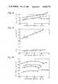
- FIG. 2is a graphical presentation of the relationship between riser outlet temperature and conversion.
- FIG. 3is a graphical presentation of conversion related to average riser temperature.
- FIG. 4is a graphical presentation of the temperature profile along the riser for different vacuum residuum injection points.
- FIGS. 5 and 6are graphical representations of the naphtha and dry gas yields from cracked vacuum residuum.
- FIGS. 7-9are a graphical representation of the C 3 -C 4 yields from cracked vacuum residuum.
- FIGS. 10 and 11are graphical representation of the C 3 plus liquids and naphtha plus light cycle gas oil yields from cracked vacuum residuum.
- FIGS. 12 and 13are a graphical representation of the quality of naphtha produced from cracked vacuum residuum.
- FIG. 14is a graphical representation of octane barrel production from vacuum residuum cracking.
- FIG. 1An illustration of the process of this invention is shown in FIG. 1.
- a clean, freshly regenerated catalystis delivered by regenerated catalyst standpipe 220 into the initial or lower portion of riser reactor 240.
- the regenerated catalysthas a carbon content less than about 0.1 wt % and an ASTM microactivity of 60-70.
- As the catalyst enters the riserits temperature is decreased from 1300°-1400° F. by the addition of a fluidization medium delivered by line 231.
- the fluidization mediummay be steam, nitrogen or low molecular weight hydrocarbons such as methane, ethane or ethylene.
- the amount of fluidization mediummust be sufficient to fluidize the fluid zeolite catalyst in the base of riser 240 above the minimum fluidization velocity to move the catalyst toward lower injection point 238 for the hydrocarbon oil.
- Vacuum gas oil (VGO)having a boiling range of about 400°-1000° F. is heated and delivered to the injection point through conduit 40.
- the VGOenters the riser by way of a first injection nozzle (not shown) which may be a single nozzle or an arrangement of more than one nozzle which mixes oil and catalyst quickly and completely after injection.
- the amount of catalyst circulatedmust be enough to completely vaporize the oil and be sufficient to crack the oil to a slate of products containing gases, low boiling liquids and the desirable liquids of gasoline and light cycle gas oil.
- Residual oilhaving an initial boiling point of about 1000° F. and containing therein contaminants such as carbon residue, nitrogen, nickel, vanadium and sodium is delivered to injection point 242 by way of conduit 44 and second injection nozzle (not shown).
- the contaminants in the vacuum residare typically 1-20 wt % carbon residue; 1-50 ppm Ni; 1-100 ppm V; 1-10 ppm Na and 100-5000 ppm nitrogen.
- the vacuum residuumis heated before delivery to the injection nozzle by preheating or by taking hot material directly from fractionation.
- the vacuum residis quickly and thoroughly mixed with the catalyst and oil vapors already present in the reaction zone.
- Injection of the vacuum residuum at the upper injection point 242cools the reaction zone reducing further cracking of the VGO. Quenching reduces the undesirable overreaction of the primary products from VGO cracking; gasoline and light cycle gas oil. By reducing overreaction, high yields of the primary products are preserved.
- the vacuum residuumalso undergoes some reaction to products boiling below about 1000° F. The contaminants from the vacuum resid deposit on the catalyst as both temporary and permanent poisons.
- the nickel, vanadium and sodiumdeposit as permanent poisons and some nitrogen deposits as a temporary poison.
- the delayed injection of these contaminants with the vacuum residallows selective cracking of the VGO on freshly regenerated catalyst. It is thought that the vacuum residuum undergoes a minimum of cracking but cracking is increased by recycling some of the product material boiling above about 670° F.
- the mixture of catalyst and oil vaporsproceed along riser 240 to separator 120.
- the riser conversion zonecomprises the internal volume of the riser from the lower injection point 238 to the separator 120.
- the oil vaporsare removed from the separator 120 through cyclones 110 and plenum 121 and are delivered through a conduit 125 to fractionation and purification means. Entrained catalyst is separated in cyclone 110 and falls to a lower portion of the separator 120 through diplegs 111.
- the diplegsare sealed by, for example, J-valves, trickle valves, flapper valves, etc.
- the catalystflows into the stripping zone 130 containing baffles 270 or other means to contact the catalyst and stripping medium.
- the stripping mediummay be nitrogen, steam or other suitable material delivered by conduit 260 to distributor 261.
- Distributor 261uniformly disperses the stripping medium into the stripping zone 130 and removes entrained hydrocarbons.
- the hydrocarbons stripped from the catalyst and stripping mediumexit with the product vapors through cyclones 110.
- the stripped catalystleaves stripping zone 130 and is delivered to the regenerator 150 by way of standpipe 140.
- the catalystis uniformly distributed into the regenerator to facilitate the removal of coke deposited on the catalyst in the reaction zone.
- the regenerator 150contains a dense phase bed of catalyst and a dilute phase of catalyst. Most of the coke is removed in the dense phase bed.
- a combustion medium of air or oxygen and nitrogenis delivered by conduit 161 to a distribution device 160 to mix combustion medium and coked catalyst.
- Cokeis burned from the catalyst to give a flue gas containing amounts of CO 2 , SO 2 , SO 3 and NO X .
- the combustion of the coke to CO 2is preferably carried out at a regenerator temperature at least about 1200° F. but less than about 1400° F. in the presence of a combustion promoter such as platinum so that 0.1 wt % or less residual carbon is left on the catalyst.
- the flue gaspasses through the regenerator dilute phase, cyclones 25, plenum 26 and flue gas line 27 for further processing.
- catalystis separated and returned to the dense bed by way of diplegs 28.
- the regenerated catalystflows from the dense bed to standpipe 220.
- Slide valve 30regulates the flow of regenerated catalyst from standpipe 220 to riser 240.
- FIGS. 2-14are discussed in the Example.
- This inventionconcerns the cracking of a vacuum residuum fraction to gasoline and lighter products in the presence of a fluid cracking catalyst at temperatures in the range of 900° F. to 1100° F.
- Residual oil mixed with VGO and charged to the base of the reaction zonecauses large amounts of carbon to deposit on the catalyst which blocks catalyst pores. This carbon deposition prevents VGO from reaching active sites of the fluid zeolite catalyst. The result is a decrease in conversion and gasoline yield from the VGO.
- charging the residual oil to not more than the final 20 vol % of the reaction zoneallows the VGO portion of the feed to crack on regenerated catalyst which contains less than 0.1 wt % carbon.
- the regenerated catalyst temperatureis maintained at 1300° to 1400° F. such that the catalyst circulation rate needed to reach riser outlet temperatures of 900° F. and higher is less than would be needed if the regenerator were maintained at less than 1300° F.
- the VGO and catalysttravel through at least 80 vol % and preferably 80 to 90 vol % of the reaction zone to a point where the residual oil is injected.
- the residual oilquenches the reaction of the VGO and prevents secondary cracking of the primary product to lighter compounds by quickly lowering the reaction temperature. Carbon contained in the residual oil quickly deposits on the catalyst, blocking the pores and decreasing the rate of the cracking reactions. The more easily cracked molecules in the residual oil crack in this short contact time without undergoing secondary cracking to light hydrocarbons. Data show that coke make is not reduced by this downstream injection of the residual oil; however, dry gas make is reduced.
- the increase in coke makeis less than the increase in the carbon residue content of the feed resulting from the addition of high carbon residue content residual oil.
- the increase in coke makeis also independent of the residence time of the residual oil.
- the regeneratorIn order to take full advantage of the downstream injection of the residual oil, the regenerator must be operated in a complete combustion mode. The flue gas exiting the regenerator should contain less than 0.5 vol % carbon monoxide and the regenerated catalyst must contain less than 0.1 wt % carbon. In order that more residual oil may be processed in those cases where the regenerator metallurgy is limiting, water may be added to the feed to remove additional heat from the regenerator by vaporization of the water.
- the catalyst employed in the present inventioncomprises a large pore crystalline aluminosilicate customarily referred to as zeolite and an active metal oxide, as exemplified by silica-alumina gel or clay.
- the zeolites employed as cracking catalysts hereinpossess ordered rigid three-dimensional structures having uniform pore diameters within the range of from about 5 to about 15 Angstroms.
- the crystalline zeolitic catalysts employed hereincomprise about 1 to 25 wt % zeolite, about 10 to 50 wt % alumina and the remainder silica.
- zeolitesare those known as X type zeolite and Y type zeolite wherein at least a substantial portion of the alkali metal ions from the original preparation have been replaced with such cations as hydrogen and/or metal or combinations of metals such as barium, calcium, magnesium, manganese or rare earth metals.
- equilibrium or fresh cracking catalystshould be flushed through the unit daily to maintain the desired activity and reduce the dry gas make. Dry gas production and activity loss is minimized by passivation of the metals using passivators available in the industry or by the use of higher than normal dispersion or fluidization steam rates.
- the inventionis distinguished from the prior art by the injection of the vacuum residuum fraction in the last 10 to 20 vol % of the riser.
- This processrequires complete combustion of the coke to carbon dioxide with excess oxygen and less than 0.5 vol % carbon monoxide in the regenerator flue gas such that the regenerated catalyst carries less than 0.1 wt % carbon.
- Regenerator temperatureshould be maintained above 1300° F. such that catalyst circulation and catalyst-to-oil ratio can be kept low.
- the riser outlet temperatureshould be maintained above 900° F. preferably 900° F. to 975° F. such that the VGO, in the reaction zone before the residual oil is injected, will react at temperatures between 1000° F. and 1200° F. Contrary to the teaching of the prior art, injection of a diluent vapor to reduce partial pressure of the hydrocarbons was found to be unnecessary unless water injection is used to reduce regenerator temperature.
- a 1000+° F. residual oilis cracked with vacuum gas oil to produce a gasoline and lighter boiling fraction.
- the residual oilshould be injected at a point in the riser such that the residence time is maintained between 0.25 and 0.6 seconds, preferably between 0.4 and 0.5 seconds.
- the relative amounts of vacuum resid to the total hydrocarbon feedwas not found to be critical.
- the characteristics of the individual vacuum resid feedstockdefines the amount that can be charged.
- About 5 to 20 wt % of the total hydrocarbon feedstockcan be vacuum resid with 10 to 15 wt % being the preferred range as shown in runs 8-10 of the data.
- Paraffinic residsyield less desirable products. They also run hotter which results in overcracking to gaseous products. Highly paraffinic resids are limited to 5 wt % of the total hydrocarbon feedstock with the exact amount determined by demand and downstream capacity. Aromatic resids produce a larger amount of the more desirable liquid hydrocarbon products. Aromatic resids may be employed in an amount of up to 20 wt %.
- Carbon content of the vacuum residis also a controlling variable. Resids with larger amounts of carbon contaminants coke catalyst to a greater degree and are best injected further down stream, to 10 vol % or less of the riser. Cleaner vacuum resids can be injected in 10 vol % up to 20 vol % of the riser. The injection of carbon containing resids changes the heat balance of the process. High carbon contamination coking catalyst may dictate the backing out of resid to the lower 5 wt % limit to keep regenerator temperature within the upper 1400° F. limit. Less carbon contaminated resids are injected to the full 20 vol % of the riser to take full advantage of the quenching of the gas oil cracking.
- Runs 1-3provided base data in which VGO alone was cracked to give a high yield of debutanized (DB) naphtha.
- Runs 4 and 5were the results of adding 1000+F. vacuum resid to the base of the riser.
- Runs 6 to 10were the result of adding 1000+° F. vacuum resid to points down the riser from the base so that the resid contacted about 90% of the riser volume in runs 6 and 7 and 10% of the riser volume in runs 8, 9 and 10.
- FIGS. 2 to 14report the results from this series of test runs.
- FIG. 2is the normal relationship of riser outlet temperature to conversion.
- FIG. 3shows conversion related to average riser temperature.
- the average riser temperature usedwas the arithmetic average of four temperatures measured at points approximately 33, 50 and 67% along the riser length and at the riser outlet. The riser was of constant diameter along its length. Of particular note is that the relation between average riser temperature and conversion is not affected by the point where the resid is injected.
- FIG. 4reports the temperature profiles through the riser which were observed from the 950° F. riser outlet temperature run from each of the resid injection points.
- the temperature profilesindicate that injecting the resid at the point which allowed only 10% of the riser to be contacted by the resid allowed the vacuum gas oil to react at a very high riser temperature.
- the curve in FIG. 5 for 100% VGO feedshows that these temperatures resulted in a low yield of DB naphtha because of secondary reaction of the naphtha to undesired products.
- FIGS. 5 and 6show that the normal injection of resid with the fresh feed at the riser base reduced the naphtha yield with a corresponding, though not equivalent, increase in dry gas. Reducing the riser length used to react the resid increased the DB naphtha yield while reducing the dry gas.
- FIGS. 7 to 9show that of the C.sub.
- FIG. 10shows that injecting the resid downstream from the VGO resulted in a higher volume yield of C 3 plus liquid than when the resid was added to the VGO feed at the base of the riser.
- FIG. 11shows that the portion of the C 3 plus material which is naphtha and light cycle gas oil-LCGO (650° F. ASTM end point) also increased when the resid was injected downstream from the VGO.
- the quality of the DB naphthais shown in FIGS. 12 and 13.
- the resultsshow that resid injected near the riser outlet produces a naphtha having higher RON and MON than when the resid was injected with the VGO feed or slightly downstream of the VGO feed.
- the RON and MONwere even higher with resid added than when VGO was cracked alone.
- the most significant result of injecting the resid near the riser outletis shown in FIG. 14. Allowing the VGO to react through 90 vol % of the riser before injecting resid allowed the same amount of octane barrel production per barrel of hydrocarbon feed as obtained with VGO cracking alone. This means that octane barrels were produced as efficiently from the resid as from the VGO.
Landscapes
- Chemical & Material Sciences (AREA)
- Oil, Petroleum & Natural Gas (AREA)
- Engineering & Computer Science (AREA)
- Chemical Kinetics & Catalysis (AREA)
- General Chemical & Material Sciences (AREA)
- Organic Chemistry (AREA)
- Production Of Liquid Hydrocarbon Mixture For Refining Petroleum (AREA)
Abstract
Description
______________________________________ Reactor Pressure 25 psig Regenerator Flue Gas O.sub.2 3 vol % Carbon on Regenerated Catalyst 0.1 wt % Fluidization Steam 0.16 lb moles/bbl fresh feed Fluidization Nitrogen 0.58 lb moles/bbl fresh feed ______________________________________
TABLE I ______________________________________ INSPECTION TESTS ON CATALYST* EQUILIBRIUM FRESH ______________________________________ METALS ON CATALYST Cu WPPM 77 13 Ni 4577 11 Fe 6300 3400 Cr 657 667 V 965 63 Na (WT %) 0.78 0.68 ACTIVITY (D + L)** 57 65 SURFACE AREA (M.sup.2 /gm) 104 288 DENSITY (lb/ft.sup.3) Compacted 58.9 53.6 PARTICLE SIZE (micron) 0-10 2 4 20-40 22 20 40-80 55 53 80+ 21 23 AVERAGE 62 63 PORE VOLUME, cc/gram 0.36 0.48 ______________________________________ *Filtrol ® ROC1 **Catalyst activity for cracking VGO, Distillate and Losses Bench Scale Method For Determining Activity of Cracking Catalyst In Powdered Form, H. McReynolds, Paper at API 25th Annual Meeting, Nov. 10, 1947
TABLE II ______________________________________ INSPECTION TESTS ON CHARGESTOCKS VACUUM DESCRIPTION VGO-1 RESID ______________________________________ GRAVITY, API 24.8 9.8 DISTILLATION, °F. IBP/5 593/672 1000+ 10/20 685/708 30/40 721/735 50 749 60/70 760+/ 80/90 35/EP VISCOSITY, cSt AT 76.7° C. 16.54 4728 AT 100° C. 8.49 273 POUR, °F.,ASTM UPPER 90 120 SULFUR, WT % 0.42 1.41 TOTAL NITROGEN, WPPM 800 4800 ANILINE PT, °F. 204 -- BROMINE NUMBER 1.6 -- AROMATICS, WT % 37.4 -- nC.sub.5 INSOLUBLES, WT % 0.0 8.42 CARBON RESIDUE, WT % 0.75 14.4 ASH,WT % 0 0.02 METALS, X-RAY, WPPM Ni, V <1,<1 28,71 Fe,1,0 32,8 Cu Cr 0 2 SODIUM, WPPM <1 30 ______________________________________
TABLE III __________________________________________________________________________ALTERNATE INJECTION POINTS FOR VACUUM RESID RUN NO. 1 2 3 4 5 6 7 8 9 10 __________________________________________________________________________Test Period 2808 2808 2808 2808 2808 2809 2809 2808 2808 2809 A/B C/D/G/H E/F/J/K L/M P C/D/E F/G V/W Y/Z A VGO Feed Rate, 1/hr. 23.4 23.7 23.9 20.9 20.6 21.0 21.3 20.9 20.5 20.8 Resid Feed Rate, 1/hr. -- -- -- 3.0.sup.1 2.9.sup.1 3.0.sup.2 3.0.sup.2 2.9.sup.3 3.2.sup.3 2.9.sup.3 Riser Outlet Temperature, °F. 925 950 975 975 949 977 952 973 950 924 Regenerator Temperature, °F. 1248 1258 1278 1367 1365 1355 1373 1364 1372 1376 Cooling Air, SCFH -- -- -- (468) (657) (48) (148) (0) (190) (82) VGO Preheat Temperature, °F. 551 551 551 552 549 555 553 558 552 550 Resid Preheat Temperature, °F. -- -- -- 552 549 337 313 475 482 479 Riser Temperature, 1st Section 949 974 999 1003 976 999 975 1028 1008 985 2nd Section 938 964 988 992 966 996 970 1022 1003 979 3rd Section 926 950 975 976 952 978 954 1006 986 962 Hydrocarbon Yields Wt % of Fresh Feed H.sub.2 S 0.35 0.36 0.36 0.42 0.47 0.37 0.34 0.36 0.34 0.35 H.sub.2 --C.sub.2 Dry Gas 3.00 4.32 5.78 7.34 5.97 5.77 4.57 5.31 4.20 3.30 C.sub.3 = 3.67 4.80 5.66 4.63 3.74 4.82 3.81 5.08 4.03 3.36 C.sub.3 0.97 1.31 1.56 1.63 1.51 1.27 1.11 1.32 1.06 0.89 iC.sub.4 2.17 2.72 3.00 1.49 1.15 1.70 1.45 2.24 1.72 1.52 nC.sub.4 0.98 1.04 1.16 0.93 0.73 0.70 0.66 0.82 0.72 0.63 C.sub.4 = 5.40 6.79 7.80 6.43 5.28 7.09 5.71 7.24 6.07 5.17 Total DB Naptha 430° F. EP 47.90 48.96 48.42 43.54 41.55 46.51 43.80 48.27 47.56 47.92 LOGO (430-650° F.) 18.34 15.76 13.64 15.72 16.96 14.89 17.39 13.45 15.15 14.94 HCGO (650° F.+) 13.06 9.37 7.66 12.26 16.87 11.19 15.58 9.91 13.42 16.27 Coke 4.17 4.57 4.97 5.62 5.77 5.69 5.57 5.99 5.73 5.65 C.sub.3 + Liquid, vol % 109.8 110.4 109.1 103.6 103.4 106.8 106.3 107.9 107.4 108.2 Conversion, vol % 70.09 76.50 80.64 74.18 67.67 75.60 68.28 78.66 73.22 69.31 DB Naphtha RON(o)/MON(o) 90.4/ 91.8/ 93.0/ 92.4/ 91.2/ 93.5/ 91.4/ 93.3/ 92.6/ 91.4/ 78.5 79.5 81.0 79.6 78.5 79.8 78.7 81.0 79.7 79.0 Total DB Naphtha, Vol % of 58.62 60.03 58.78 53.02 50.73 56.93 53.74 59.28 58.42 58.67 Fresh Feed LCGO, Vol % of Fresh Feed 18.17 15.32 13.01 15.32 17.02 14.63 17.39 12.94 14.91 15.15 HCGO, Vol % of Fresh Feed 11.74 8.19 6.34 10.49 15.31 9.77 14.34 8.40 11.88 15.54 __________________________________________________________________________ .sup.1 Base of riser; .sup.2 vacuum resid to riser at 10% downstream; .sup.3 vacuum resid to riser at 90% downstream
Claims (10)
Priority Applications (1)
| Application Number | Priority Date | Filing Date | Title |
|---|---|---|---|
| US06/777,146US4624771A (en) | 1985-09-18 | 1985-09-18 | Fluid catalytic cracking of vacuum residuum oil |
Applications Claiming Priority (1)
| Application Number | Priority Date | Filing Date | Title |
|---|---|---|---|
| US06/777,146US4624771A (en) | 1985-09-18 | 1985-09-18 | Fluid catalytic cracking of vacuum residuum oil |
Publications (1)
| Publication Number | Publication Date |
|---|---|
| US4624771Atrue US4624771A (en) | 1986-11-25 |
Family
ID=25109418
Family Applications (1)
| Application Number | Title | Priority Date | Filing Date |
|---|---|---|---|
| US06/777,146Expired - LifetimeUS4624771A (en) | 1985-09-18 | 1985-09-18 | Fluid catalytic cracking of vacuum residuum oil |
Country Status (1)
| Country | Link |
|---|---|
| US (1) | US4624771A (en) |
Cited By (37)
| Publication number | Priority date | Publication date | Assignee | Title |
|---|---|---|---|---|
| US4764268A (en)* | 1987-04-27 | 1988-08-16 | Texaco Inc. | Fluid catalytic cracking of vacuum gas oil with a refractory fluid quench |
| US4892643A (en)* | 1986-09-03 | 1990-01-09 | Mobil Oil Corporation | Upgrading naphtha in a single riser fluidized catalytic cracking operation employing a catalyst mixture |
| US4957617A (en)* | 1986-09-03 | 1990-09-18 | Mobil Oil Corporation | Fluid catalytic cracking |
| US4978440A (en)* | 1984-10-30 | 1990-12-18 | Mobil Oil Corporation | Quenched catalytic cracking process |
| US4988430A (en)* | 1989-12-27 | 1991-01-29 | Uop | Supplying FCC lift gas directly from product vapors |
| US5087349A (en)* | 1988-11-18 | 1992-02-11 | Stone & Webster Engineering Corporation | Process for selectively maximizing product production in fluidized catalytic cracking of hydrocarbons |
| US5104517A (en)* | 1990-05-17 | 1992-04-14 | Uop | Vented riser apparatus and method |
| US5141625A (en)* | 1989-12-27 | 1992-08-25 | Uop | Second stage stripping and lift gas supply |
| US5143875A (en)* | 1991-02-06 | 1992-09-01 | Mobil Oil Corporation | Bubbling dense bed catalyst regenerator with higher efficiency base region |
| US5154818A (en)* | 1990-05-24 | 1992-10-13 | Mobil Oil Corporation | Multiple zone catalytic cracking of hydrocarbons |
| US5167795A (en)* | 1988-01-28 | 1992-12-01 | Stone & Webster Engineering Corp. | Process for the production of olefins and aromatics |
| US5176815A (en)* | 1990-12-17 | 1993-01-05 | Uop | FCC process with secondary conversion zone |
| US5234578A (en)* | 1988-08-26 | 1993-08-10 | Uop | Fluidized catalytic cracking process utilizing a high temperature reactor |
| US5310477A (en)* | 1990-12-17 | 1994-05-10 | Uop | FCC process with secondary dealkylation zone |
| US5314610A (en)* | 1992-05-29 | 1994-05-24 | Abb Lummus Crest Inc. | Staged catalytic cracking process |
| US5328592A (en)* | 1992-12-24 | 1994-07-12 | Uop | FCC reactor with tube sheet separation |
| US6113776A (en)* | 1998-06-08 | 2000-09-05 | Uop Llc | FCC process with high temperature cracking zone |
| US6123832A (en)* | 1998-04-28 | 2000-09-26 | Exxon Research And Engineering Co. | Fluid catalytic cracking process for converting hydrocarbon mixtures |
| CN1100118C (en)* | 2000-02-22 | 2003-01-29 | 中国石油化工集团公司 | Petroleum hydrocarbon catalytic cracking process of producing diesel oil and high-octane number gasoline |
| US20090299119A1 (en)* | 2008-05-29 | 2009-12-03 | Kellogg Brown & Root Llc | Heat Balanced FCC For Light Hydrocarbon Feeds |
| US20160281002A1 (en)* | 2013-11-18 | 2016-09-29 | Indian Oil Corporation Limited | Process and a system for enhancing liquid yield of heavy hydrocarbon feedstock |
| US10435339B2 (en)* | 2017-05-12 | 2019-10-08 | Marathon Petroleum Company Lp | FCC feed additive for propylene/butylene maximization |
| US11802257B2 (en) | 2022-01-31 | 2023-10-31 | Marathon Petroleum Company Lp | Systems and methods for reducing rendered fats pour point |
| US11860069B2 (en) | 2021-02-25 | 2024-01-02 | Marathon Petroleum Company Lp | Methods and assemblies for determining and using standardized spectral responses for calibration of spectroscopic analyzers |
| US11891581B2 (en) | 2017-09-29 | 2024-02-06 | Marathon Petroleum Company Lp | Tower bottoms coke catching device |
| US11898109B2 (en) | 2021-02-25 | 2024-02-13 | Marathon Petroleum Company Lp | Assemblies and methods for enhancing control of hydrotreating and fluid catalytic cracking (FCC) processes using spectroscopic analyzers |
| US11905479B2 (en) | 2020-02-19 | 2024-02-20 | Marathon Petroleum Company Lp | Low sulfur fuel oil blends for stability enhancement and associated methods |
| US11905468B2 (en) | 2021-02-25 | 2024-02-20 | Marathon Petroleum Company Lp | Assemblies and methods for enhancing control of fluid catalytic cracking (FCC) processes using spectroscopic analyzers |
| US11970664B2 (en) | 2021-10-10 | 2024-04-30 | Marathon Petroleum Company Lp | Methods and systems for enhancing processing of hydrocarbons in a fluid catalytic cracking unit using a renewable additive |
| US11975316B2 (en) | 2019-05-09 | 2024-05-07 | Marathon Petroleum Company Lp | Methods and reforming systems for re-dispersing platinum on reforming catalyst |
| US12000720B2 (en) | 2018-09-10 | 2024-06-04 | Marathon Petroleum Company Lp | Product inventory monitoring |
| US12031094B2 (en) | 2021-02-25 | 2024-07-09 | Marathon Petroleum Company Lp | Assemblies and methods for enhancing fluid catalytic cracking (FCC) processes during the FCC process using spectroscopic analyzers |
| US12031676B2 (en) | 2019-03-25 | 2024-07-09 | Marathon Petroleum Company Lp | Insulation securement system and associated methods |
| US12306076B2 (en) | 2023-05-12 | 2025-05-20 | Marathon Petroleum Company Lp | Systems, apparatuses, and methods for sample cylinder inspection, pressurization, and sample disposal |
| US12311305B2 (en) | 2022-12-08 | 2025-05-27 | Marathon Petroleum Company Lp | Removable flue gas strainer and associated methods |
| US12345416B2 (en) | 2019-05-30 | 2025-07-01 | Marathon Petroleum Company Lp | Methods and systems for minimizing NOx and CO emissions in natural draft heaters |
| US12415962B2 (en) | 2023-11-10 | 2025-09-16 | Marathon Petroleum Company Lp | Systems and methods for producing aviation fuel |
Citations (5)
| Publication number | Priority date | Publication date | Assignee | Title |
|---|---|---|---|---|
| US3847793A (en)* | 1972-12-19 | 1974-11-12 | Mobil Oil | Conversion of hydrocarbons with a dual cracking component catalyst comprising zsm-5 type material |
| US4147617A (en)* | 1978-04-06 | 1979-04-03 | Mobil Oil Corporation | Processing hydrocarbon feed of high carbon residue and high metals content |
| US4218306A (en)* | 1979-01-15 | 1980-08-19 | Mobil Oil Corporation | Method for catalytic cracking heavy oils |
| US4419221A (en)* | 1981-10-27 | 1983-12-06 | Texaco Inc. | Cracking with short contact time and high temperatures |
| US4422925A (en)* | 1981-12-28 | 1983-12-27 | Texaco Inc. | Catalytic cracking |
- 1985
- 1985-09-18USUS06/777,146patent/US4624771A/ennot_activeExpired - Lifetime
Patent Citations (5)
| Publication number | Priority date | Publication date | Assignee | Title |
|---|---|---|---|---|
| US3847793A (en)* | 1972-12-19 | 1974-11-12 | Mobil Oil | Conversion of hydrocarbons with a dual cracking component catalyst comprising zsm-5 type material |
| US4147617A (en)* | 1978-04-06 | 1979-04-03 | Mobil Oil Corporation | Processing hydrocarbon feed of high carbon residue and high metals content |
| US4218306A (en)* | 1979-01-15 | 1980-08-19 | Mobil Oil Corporation | Method for catalytic cracking heavy oils |
| US4419221A (en)* | 1981-10-27 | 1983-12-06 | Texaco Inc. | Cracking with short contact time and high temperatures |
| US4422925A (en)* | 1981-12-28 | 1983-12-27 | Texaco Inc. | Catalytic cracking |
Cited By (51)
| Publication number | Priority date | Publication date | Assignee | Title |
|---|---|---|---|---|
| US4978440A (en)* | 1984-10-30 | 1990-12-18 | Mobil Oil Corporation | Quenched catalytic cracking process |
| US4892643A (en)* | 1986-09-03 | 1990-01-09 | Mobil Oil Corporation | Upgrading naphtha in a single riser fluidized catalytic cracking operation employing a catalyst mixture |
| US4957617A (en)* | 1986-09-03 | 1990-09-18 | Mobil Oil Corporation | Fluid catalytic cracking |
| US4764268A (en)* | 1987-04-27 | 1988-08-16 | Texaco Inc. | Fluid catalytic cracking of vacuum gas oil with a refractory fluid quench |
| US5167795A (en)* | 1988-01-28 | 1992-12-01 | Stone & Webster Engineering Corp. | Process for the production of olefins and aromatics |
| US5234578A (en)* | 1988-08-26 | 1993-08-10 | Uop | Fluidized catalytic cracking process utilizing a high temperature reactor |
| US5087349A (en)* | 1988-11-18 | 1992-02-11 | Stone & Webster Engineering Corporation | Process for selectively maximizing product production in fluidized catalytic cracking of hydrocarbons |
| US4988430A (en)* | 1989-12-27 | 1991-01-29 | Uop | Supplying FCC lift gas directly from product vapors |
| US5141625A (en)* | 1989-12-27 | 1992-08-25 | Uop | Second stage stripping and lift gas supply |
| US5104517A (en)* | 1990-05-17 | 1992-04-14 | Uop | Vented riser apparatus and method |
| US5364515A (en)* | 1990-05-17 | 1994-11-15 | Uop | Fluidized catalytic cracking of hydrocarbons utilizing a vented riser |
| US5294331A (en)* | 1990-05-17 | 1994-03-15 | Uop | FCC process utilizing a vented riser |
| US5302280A (en)* | 1990-05-17 | 1994-04-12 | Uop | Fluidized catalytic cracking utilizing a vented riser |
| US5154818A (en)* | 1990-05-24 | 1992-10-13 | Mobil Oil Corporation | Multiple zone catalytic cracking of hydrocarbons |
| US5176815A (en)* | 1990-12-17 | 1993-01-05 | Uop | FCC process with secondary conversion zone |
| US5310477A (en)* | 1990-12-17 | 1994-05-10 | Uop | FCC process with secondary dealkylation zone |
| US5143875A (en)* | 1991-02-06 | 1992-09-01 | Mobil Oil Corporation | Bubbling dense bed catalyst regenerator with higher efficiency base region |
| US5314610A (en)* | 1992-05-29 | 1994-05-24 | Abb Lummus Crest Inc. | Staged catalytic cracking process |
| US5328592A (en)* | 1992-12-24 | 1994-07-12 | Uop | FCC reactor with tube sheet separation |
| US6123832A (en)* | 1998-04-28 | 2000-09-26 | Exxon Research And Engineering Co. | Fluid catalytic cracking process for converting hydrocarbon mixtures |
| US6113776A (en)* | 1998-06-08 | 2000-09-05 | Uop Llc | FCC process with high temperature cracking zone |
| US6616899B1 (en) | 1998-06-08 | 2003-09-09 | Uop Llc | FCC process with temperature cracking zone |
| CN1100118C (en)* | 2000-02-22 | 2003-01-29 | 中国石油化工集团公司 | Petroleum hydrocarbon catalytic cracking process of producing diesel oil and high-octane number gasoline |
| US20090299119A1 (en)* | 2008-05-29 | 2009-12-03 | Kellogg Brown & Root Llc | Heat Balanced FCC For Light Hydrocarbon Feeds |
| US20160281002A1 (en)* | 2013-11-18 | 2016-09-29 | Indian Oil Corporation Limited | Process and a system for enhancing liquid yield of heavy hydrocarbon feedstock |
| US9944862B2 (en)* | 2013-11-18 | 2018-04-17 | Indian Oil Corporation Limited | Process and a system for enhancing liquid yield of heavy hydrocarbon feedstock |
| US10435339B2 (en)* | 2017-05-12 | 2019-10-08 | Marathon Petroleum Company Lp | FCC feed additive for propylene/butylene maximization |
| US11891581B2 (en) | 2017-09-29 | 2024-02-06 | Marathon Petroleum Company Lp | Tower bottoms coke catching device |
| US12000720B2 (en) | 2018-09-10 | 2024-06-04 | Marathon Petroleum Company Lp | Product inventory monitoring |
| US12031676B2 (en) | 2019-03-25 | 2024-07-09 | Marathon Petroleum Company Lp | Insulation securement system and associated methods |
| US11975316B2 (en) | 2019-05-09 | 2024-05-07 | Marathon Petroleum Company Lp | Methods and reforming systems for re-dispersing platinum on reforming catalyst |
| US12345416B2 (en) | 2019-05-30 | 2025-07-01 | Marathon Petroleum Company Lp | Methods and systems for minimizing NOx and CO emissions in natural draft heaters |
| US11920096B2 (en) | 2020-02-19 | 2024-03-05 | Marathon Petroleum Company Lp | Low sulfur fuel oil blends for paraffinic resid stability and associated methods |
| US12421467B2 (en) | 2020-02-19 | 2025-09-23 | Marathon Petroleum Company Lp | Low sulfur fuel oil blends for stability enhancement and associated methods |
| US11905479B2 (en) | 2020-02-19 | 2024-02-20 | Marathon Petroleum Company Lp | Low sulfur fuel oil blends for stability enhancement and associated methods |
| US12221583B2 (en) | 2021-02-25 | 2025-02-11 | Marathon Petroleum Company Lp | Assemblies and methods for enhancing control of hydrotreating and fluid catalytic cracking (FCC) processes using spectroscopic analyzers |
| US12163878B2 (en) | 2021-02-25 | 2024-12-10 | Marathon Petroleum Company Lp | Methods and assemblies for determining and using standardized spectral responses for calibration of spectroscopic analyzers |
| US11860069B2 (en) | 2021-02-25 | 2024-01-02 | Marathon Petroleum Company Lp | Methods and assemblies for determining and using standardized spectral responses for calibration of spectroscopic analyzers |
| US11905468B2 (en) | 2021-02-25 | 2024-02-20 | Marathon Petroleum Company Lp | Assemblies and methods for enhancing control of fluid catalytic cracking (FCC) processes using spectroscopic analyzers |
| US11906423B2 (en) | 2021-02-25 | 2024-02-20 | Marathon Petroleum Company Lp | Methods, assemblies, and controllers for determining and using standardized spectral responses for calibration of spectroscopic analyzers |
| US12031094B2 (en) | 2021-02-25 | 2024-07-09 | Marathon Petroleum Company Lp | Assemblies and methods for enhancing fluid catalytic cracking (FCC) processes during the FCC process using spectroscopic analyzers |
| US11898109B2 (en) | 2021-02-25 | 2024-02-13 | Marathon Petroleum Company Lp | Assemblies and methods for enhancing control of hydrotreating and fluid catalytic cracking (FCC) processes using spectroscopic analyzers |
| US11921035B2 (en) | 2021-02-25 | 2024-03-05 | Marathon Petroleum Company Lp | Methods and assemblies for determining and using standardized spectral responses for calibration of spectroscopic analyzers |
| US11885739B2 (en) | 2021-02-25 | 2024-01-30 | Marathon Petroleum Company Lp | Methods and assemblies for determining and using standardized spectral responses for calibration of spectroscopic analyzers |
| US12338396B2 (en) | 2021-10-10 | 2025-06-24 | Marathon Petroleum Company Lp | Methods and systems for enhancing processing of hydrocarbons in a fluid catalytic cracking unit using a renewable additive |
| US11970664B2 (en) | 2021-10-10 | 2024-04-30 | Marathon Petroleum Company Lp | Methods and systems for enhancing processing of hydrocarbons in a fluid catalytic cracking unit using a renewable additive |
| US12297403B2 (en) | 2022-01-31 | 2025-05-13 | Marathon Petroleum Company Lp | Systems and methods for reducing rendered fats pour point |
| US11802257B2 (en) | 2022-01-31 | 2023-10-31 | Marathon Petroleum Company Lp | Systems and methods for reducing rendered fats pour point |
| US12311305B2 (en) | 2022-12-08 | 2025-05-27 | Marathon Petroleum Company Lp | Removable flue gas strainer and associated methods |
| US12306076B2 (en) | 2023-05-12 | 2025-05-20 | Marathon Petroleum Company Lp | Systems, apparatuses, and methods for sample cylinder inspection, pressurization, and sample disposal |
| US12415962B2 (en) | 2023-11-10 | 2025-09-16 | Marathon Petroleum Company Lp | Systems and methods for producing aviation fuel |
Similar Documents
| Publication | Publication Date | Title |
|---|---|---|
| US4624771A (en) | Fluid catalytic cracking of vacuum residuum oil | |
| US4764268A (en) | Fluid catalytic cracking of vacuum gas oil with a refractory fluid quench | |
| US5846402A (en) | Process for catalytic cracking of petroleum based feed stocks | |
| US5154818A (en) | Multiple zone catalytic cracking of hydrocarbons | |
| US3944482A (en) | Process for the cracking of high metals content feedstocks | |
| AU766848B2 (en) | Fluid cat cracking with high olefins production | |
| CA1205407A (en) | Method and apparatus for converting oil feeds | |
| EP0171460B1 (en) | Residual oil cracking process using dry gas as lift gas initially in riser reactor | |
| US4465588A (en) | Process for cracking high metals content feedstock | |
| CN108350367B (en) | Method and system for fluid catalytic cracking | |
| US6495028B1 (en) | Catalytic conversion process for producing isobutane and isoparaffin-enriched gasoline | |
| JP2020015912A (en) | Integrated solvent-deasphalting and fluid catalytic cracking method for light olefin production | |
| EP0154676A2 (en) | Use of dual-function lift gas in a FCC reactor riser | |
| JPH06322377A (en) | Method and apparatus for catalytically cracking paraffin-rich feedstock containing high and low con-carbon components | |
| US4853105A (en) | Multiple riser fluidized catalytic cracking process utilizing hydrogen and carbon-hydrogen contributing fragments | |
| US5318695A (en) | Fluid cracking process for producing low emissions fuels | |
| US3801493A (en) | Slack wax cracking in an fccu with a satellite reactor | |
| EP0600686B1 (en) | Fluid catalytic cracking process for producing light olefins | |
| EP0593823B1 (en) | FCC Riser discharge separation and quench | |
| JP3444884B2 (en) | Fluid catalytic cracking | |
| US5318692A (en) | FCC for producing low emission fuels from high hydrogen and low nitrogen and aromatic feeds | |
| GB1570682A (en) | Hydrocarbon catalytic cracking process | |
| US5314612A (en) | Fluid catalytic cracking process for producing low emissions fuels | |
| US20040140246A1 (en) | Process for upgrading fcc product with additional reactor | |
| US5217602A (en) | FCC riser discharge separation and quench |
Legal Events
| Date | Code | Title | Description |
|---|---|---|---|
| AS | Assignment | Owner name:TEXACO INC., 2000 WESTCHESTER AVE., WHITE PLAINS, Free format text:ASSIGNMENT OF ASSIGNORS INTEREST.;ASSIGNORS:LANE, PHILIP A.;SCHRADER, CHARLES H.;CLAUSEN, GLENN A.;AND OTHERS;REEL/FRAME:004648/0447 Effective date:19850912 Owner name:TEXACO INC., A CORP OF DE,NEW YORK Free format text:ASSIGNMENT OF ASSIGNORS INTEREST;ASSIGNORS:LANE, PHILIP A.;SCHRADER, CHARLES H.;CLAUSEN, GLENN A.;AND OTHERS;REEL/FRAME:004648/0447 Effective date:19850912 | |
| STCF | Information on status: patent grant | Free format text:PATENTED CASE | |
| FEPP | Fee payment procedure | Free format text:PAYOR NUMBER ASSIGNED (ORIGINAL EVENT CODE: ASPN); ENTITY STATUS OF PATENT OWNER: LARGE ENTITY | |
| FPAY | Fee payment | Year of fee payment:4 | |
| FPAY | Fee payment | Year of fee payment:8 | |
| FEPP | Fee payment procedure | Free format text:PAYER NUMBER DE-ASSIGNED (ORIGINAL EVENT CODE: RMPN); ENTITY STATUS OF PATENT OWNER: LARGE ENTITY Free format text:PAYOR NUMBER ASSIGNED (ORIGINAL EVENT CODE: ASPN); ENTITY STATUS OF PATENT OWNER: LARGE ENTITY | |
| FPAY | Fee payment | Year of fee payment:12 |