US4623761A - Telephone operator voice storage and retrieval system - Google Patents
Telephone operator voice storage and retrieval systemDownload PDFInfo
- Publication number
- US4623761A US4623761AUS06/601,711US60171184AUS4623761AUS 4623761 AUS4623761 AUS 4623761AUS 60171184 AUS60171184 AUS 60171184AUS 4623761 AUS4623761 AUS 4623761A
- Authority
- US
- United States
- Prior art keywords
- operator
- voice
- response message
- message
- played back
- Prior art date
- Legal status (The legal status is an assumption and is not a legal conclusion. Google has not performed a legal analysis and makes no representation as to the accuracy of the status listed.)
- Expired - Lifetime
Links
- 230000004044responseEffects0.000claimsabstractdescription130
- 230000015654memoryEffects0.000claimsabstractdescription31
- 238000004891communicationMethods0.000claimsdescription17
- 230000008878couplingEffects0.000claimsdescription15
- 238000010168coupling processMethods0.000claimsdescription15
- 238000005859coupling reactionMethods0.000claimsdescription15
- 230000000977initiatory effectEffects0.000claimsdescription3
- 238000000034methodMethods0.000claims16
- 230000000694effectsEffects0.000claims2
- 230000008859changeEffects0.000abstractdescription3
- 239000000872bufferSubstances0.000description25
- 238000010586diagramMethods0.000description8
- 230000009977dual effectEffects0.000description5
- 230000005236sound signalEffects0.000description5
- 238000012545processingMethods0.000description4
- 239000004020conductorSubstances0.000description3
- 238000012544monitoring processMethods0.000description3
- 230000008901benefitEffects0.000description2
- 238000001514detection methodMethods0.000description2
- 230000007246mechanismEffects0.000description2
- 238000012986modificationMethods0.000description2
- 230000004048modificationEffects0.000description2
- 230000005693optoelectronicsEffects0.000description2
- 239000004065semiconductorSubstances0.000description2
- 230000003321amplificationEffects0.000description1
- 230000009118appropriate responseEffects0.000description1
- 230000005540biological transmissionEffects0.000description1
- 238000006243chemical reactionMethods0.000description1
- 230000006872improvementEffects0.000description1
- 238000004377microelectronicMethods0.000description1
- 238000003199nucleic acid amplification methodMethods0.000description1
- 230000003287optical effectEffects0.000description1
- 230000000284resting effectEffects0.000description1
- 238000005070samplingMethods0.000description1
- 230000003068static effectEffects0.000description1
- 238000012546transferMethods0.000description1
Images


Classifications
- H—ELECTRICITY
- H04—ELECTRIC COMMUNICATION TECHNIQUE
- H04M—TELEPHONIC COMMUNICATION
- H04M3/00—Automatic or semi-automatic exchanges
- H04M3/42—Systems providing special services or facilities to subscribers
- H04M3/50—Centralised arrangements for answering calls; Centralised arrangements for recording messages for absent or busy subscribers ; Centralised arrangements for recording messages
- H04M3/51—Centralised call answering arrangements requiring operator intervention, e.g. call or contact centers for telemarketing
- H04M3/5166—Centralised call answering arrangements requiring operator intervention, e.g. call or contact centers for telemarketing in combination with interactive voice response systems or voice portals, e.g. as front-ends
- H—ELECTRICITY
- H04—ELECTRIC COMMUNICATION TECHNIQUE
- H04M—TELEPHONIC COMMUNICATION
- H04M3/00—Automatic or semi-automatic exchanges
- H04M3/42—Systems providing special services or facilities to subscribers
- H04M3/50—Centralised arrangements for answering calls; Centralised arrangements for recording messages for absent or busy subscribers ; Centralised arrangements for recording messages
- H04M3/53—Centralised arrangements for recording incoming messages, i.e. mailbox systems
- H—ELECTRICITY
- H04—ELECTRIC COMMUNICATION TECHNIQUE
- H04M—TELEPHONIC COMMUNICATION
- H04M2242/00—Special services or facilities
- H04M2242/22—Automatic class or number identification arrangements
- H—ELECTRICITY
- H04—ELECTRIC COMMUNICATION TECHNIQUE
- H04M—TELEPHONIC COMMUNICATION
- H04M3/00—Automatic or semi-automatic exchanges
- H04M3/42—Systems providing special services or facilities to subscribers
- H04M3/42025—Calling or Called party identification service
- H04M3/42034—Calling party identification service
- H04M3/42059—Making use of the calling party identifier
Definitions
- the present inventionrelates, in general, to telephone systems and is particularly directed to a call answering scheme through which a prerecorded response message is returned to the calling party, either through operator control, or automatically, while permitting the operator to remain on-line and have the ability to inject his/her voice into the communication link to the calling party without any detectable change in quality of the voice being received by the calling party.
- Operator-assisted telephone service facilitiessuch as directory assistance, PBX and Toll Service
- PBX and Toll Servicerequire that the service operator handle a large number of similar calls over the operator's work period, with the number of daily incoming requests for assistance typically varying from 800 to 1,300, depending upon the time of day and year.
- Previous attempts to reduce the operator's work timeemployed automatic response systems which contain prerecorded messages usually stored on electromechanical storage and retrieval devices (e.g. magnetic tape cassette or disk devices). Unfortunately, such systems do not alleviate the operator's burden of performing what is effectively a monotonous routine. Also, differences in voice characteristics (e.g. tonal quality, accent, gender) tend to create a negative customer reaction.
- the need to provide the operator with a mechanism for reducing the monotonous routine of answering similar types of calls while avoiding drawbacks of conventional automatic response systems, such as those mentioned above,is satisfied by a telephone operator voice storage and retrieval system that is capable of presenting to the customer (caller) a response message (selected from a library of approved answering phrases that have been determined to be the most effective for the inquiries received) in the actual voice of the operator that is on duty at the time.
- the present inventionpermits the operator to follow-up the played-back message with a conversation with the caller, without the caller detecting a difference in the characteristics of the played-back voice and the "live" operator's voice, so that operator voice response message storage and retrieval system of the invention is effectively transparent to the caller.
- the present inventionemploys a voice analyzer/synthesizer coupled between a response message memory and an audio interface to the operator's audio equipment (headset).
- the memoryis preferably a high speed/high density semiconductor RAM (such as one contained in the form of a modular cartridge) into which response messages read aloud by the operator are stored after being digitized by the voice analyzer, during the record mode of the system. After a series of approved response messages, as prepared by the on-duty operator, have been stored, the system is ready for use in responding to incoming calls. In this (playback) mode, incoming calls are answered, either by the operator or automatically and, in accordance with the type of call received, the appropriate operator's voice-enunciated response message that had been previously entered into memory is accessed.
- the audio interfacecontains automatic level control circuitry which ensures that there is effectively no difference in the audio level of the recorded voice played back to the caller and the "live" voice spoken by the operator.
- This listener transparencyis an especially attractive feature of the present invention, as it prevents the operator's "live” voice from confusing the caller, as, for example, would be the case if the response message was given in a female voice abruptly followed by the voice of a male operator handling the remainder of the live call, or releasing a portion of the call to another voice generated by a conventional automatic response system.
- the audio interface portion of the systemprovides full duplex voice transmission (and level control) capability, allowing the operator to hear the caller's voice regardless of line or equipment variations or caller's idiosyncrasies in telephone usage.
- the systemmakes use of microelectronics signal processing and storage components, making it adaptable with a variety of telephone systems and readily intercoupled with an existing operator's console.
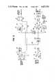
- FIG. 1is a simplified block diagram showing of the telephone operator voice message storage and retrieval scheme of the present invention
- FIG. 2is a schematic block diagram of the digitized voice storage and retrieval unit of the scheme shown in FIG. 1;
- FIG. 3is a schematic diagram of the audio interface unit of the scheme shown in FIG. 1.
- FIG. 1 of the drawingsthere is shown a generalized block diagram of the telephone operator voice storage and retrieval system of the invention which is to be associated with an operator-assisted telephone service facility.
- a link 50which includes both voice and call identification lines for handling and responding to requests from a caller or customer 70.
- the tip and sleeve portions of the telephone linkare coupled to an audio interface unit 30 (to be described in detail below with reference to FIG. 3), while those links indicating the type of incoming call are coupled to a detector 40.
- both the voice and type of call informationhave been shown as a single link 50 in FIG. 1 for purposes of simplifying the illustration and description.
- the actual signal conveying conductors and detection circuitry for establishing the type of callare conventional and need not be described here for an understanding of the invention.
- Call-type detector 40may be of conventional configuration employing a bank of indicators monitored by an operator 10 who, via a switch panel interface, selects an appropriate code for identifying the type of response message to be returned to the caller 70. This would normally involve the operator monitoring an optical read-out panel of call-type detector 40 and then, via a switch panel interface, causing the playback of a stored response message, such as from a magnetic tape cassette. Rather than have the operator perform this task, however, it is possible to employ a bank of associated detectors, such as opto-electronic detectors, coupled with the indicator unit of the call-type detector 40 of the telephone service facility of interest, which supplies a set of codes over a link 42 to a message storage and retrieval system 20, to be described below with reference to FIG. 2. In other words, the type of call being detected may be monitored manually by the operator and the information identifying the type of call coupled to the message storage and retrieval system 20 by an operator switch panel interface, or it may be handled automatically without operator intervention.
- a bank of associated detectors
- the operator 10is also coupled to the audio interface unit 30 by way of his/her headset, so that an on-line, "live" voice communication may be established between the operator 10 and the caller 70.
- the initial conversation/response voice interface between the telephone service facility and the caller 70is provided from the message storage and retrieval unit 20 without the need for the operator 10 to speak directly to the caller 70.
- thisnot only provides the intended relief for the operator 10, but ensures that the caller is supplied with the correct response message voice reply (i.e. a preestablished customer-oriented and optimized response that has been previously recorded by the operator in his/her own voice so that the message is pleasing and informative to the listener).
- Audio interface unit 30in addition to providing on-line communication capability between the operator 10 and the caller 70, serves to provide automatic voice level adjustment for all audio that is coupled to the caller 70, whether that audio be generated from the operator's headset or from the message storage and retrieval unit 20. Audio signal coupling between the audio interface unit 30 and the message storage and retrieval unit 20 is effected over input/output links 11/21.
- FIG. 2a schematic block diagram of the message storage and retrieval unit 20 is illustrated as being comprised of a voice input/output unit 12, a call type unit 13 and a control unit 14.
- Voice input/output unit 12is coupled to audio interface unit 30 by way of audio input link 11 and audio output link 21.
- Audio input signals input over link 11represent voice signals generated by the operator 10 during the response message "record" mode of operation of the system for storing response messages to be later played back to reply to incoming calls.
- These audio signalsare digitized and analyzed within the voice input/output unit 12 and stored in digital form in memory in the control unit 14.
- such stored digital encoded voice messagesare read out from memory in the control unit 14, synthesized and coupled over link 21 to the audio interface unit 30 for playback to a caller 70.
- Call type unit 13effectively comprises a buffer for storing an indication of the type of call for which a reply message is to be generated.
- Call type unit 13is coupled to the detector 40, either by way of a switch panel that is operator-controlled or through an automatic detector, such as an opto-electronic detector, which monitors the operator/attendant's telephone facility terminal.
- the data that is stored in buffer 41is accessed by a control unit 14 for selecting the appropriate response message that has been stored in memory to be read-out and generated as a reply message to be delivered to the caller 70.
- the control unit 14contains processor, memory and communication bus components for controlling the operation of message storage and retrieval unit 20 as operator-generated response messages are stored and later accessed and delivered to a caller, depending upon the type of call buffered by call type unit 13.
- audio input link 11which receives analog input signals corresponding to the audio voice supplied by the audio interface unit 30, is coupled to an analog-to-digital converter (ADC) 24.
- ADC 24samples and digitizes the audio input signal and couples the quantized-encoded sample values to a shift register 31. Shift register 31 serializes out the digitized voice signal samples supplied by ADC 24 over link 33 to a voice analyzer/synthesizer 32.
- the voice analyzer/synthesizer unit 32may be a commercially available unit from OKI Semiconductor.
- a clock sourceis coupled over link 23 to each of ADC 24, shift register 31 and analyzer/synthesizer 32. It is also coupled to a divider 25 to reduce the frequency for accessing and controlling a load or shift select circuit 26 which is coupled to ADC 24 over link 27 and to shift register 31 over link 28. Shift select logic unit 26 provides the appropriate digitized transfer coupling between ADC 24 and shift register 31, in a customary fashion.
- a separate clockis coupled over link 34 to analyzer/synthesizer 32 for providing the control of the read-out analyzer/synthesizer 32.
- the analog voice that is supplied from synthesizer portion of unit 32is coupled over link 21 to the audio interface unit 30 in FIG. 3, to be described below.
- the digitized voice components supplied from the analyzer portion of unit 32are coupled as digitized voice data over interface 35 to a buffer 36.
- the synthesizer portionreceives digitized voice data from an output buffer 37 to which voice message words read out of memory stored in the control unit 14 are coupled, as will be described below.
- Each of buffers 36, 37, 41 and a buffer 53is coupled to data bus 45 within the control unit 14.
- Buffer 53is coupled over link 43 to audio-interface unit 30 (FIG. 3) and stores a voice detection signal coupled thereto from unit 30.
- Data bus 45includes communication highway conductors for conveying both data and a portion of the address signals to be employed within the control unit 14 for accessing the various components thereof.
- data bus 45may be a commercially available Z-80 type bus structure.
- Control unit 14is an intelligent-based unit under control of microprocessor 61, which is coupled to data bus 45, to an address bus 52 and to a control bus 62 in a conventional manner.
- the clock source for microprocessor 61is coupled over link 65.
- control unit 14includes a response message memory 51, such as a static RAM in the form of a pluggable modular cartridge, and a program store unit 46.
- response message memory 51such as a static RAM in the form of a pluggable modular cartridge
- program store unit 46stores the instruction set for controlling the operation of the storage and retrieval unit and the manner in which it interfaces with the remainder of the system. As that instruction set may take on a number of forms depending upon the desires of the programmer, it will not be described in detail here. Instead, the operational scenario carried out by the program stored in memory 46 will be described, in order to provide a more efficient description of the invention.
- Control unit 14also includes a memory select logic unit 54 (consisting of combinational logic) through which microprocessor 61 selectively accesses response message storage RAM 51 or program store memory 46 via links 56 and 55, respectively.
- a memory select logic unit 54(consisting of combinational logic) through which microprocessor 61 selectively accesses response message storage RAM 51 or program store memory 46 via links 56 and 55, respectively.
- an input/output select unit logic unit 44is employed for selectively accessing the contents of buffers 36, 37 and 41 during the operation of the system.
- Each of select logic units 54 and 44is accessed by control signals on control bus 62 and address bus 52 from microprocessor 61.
- call type unit 13which comprises buffer 41
- call type unit 13may be coupled to the control terminal of a telephone service facility either through the operator's control switch panel for manually controlling the response message to be generated to the caller, or through an interface unit which automatically generates control codes to be stored in buffer 41 for accessing the response messages stored in memory 51. In either case, these codes are coupled over a link 42 and stored in buffer 41.
- an additional buffer 53is coupled over link 43. Buffer 53 is monitored by processor 61 for initiating the operation of the storage and retrieval unit of FIG. 2.
- link 43is coupled to a voice detector within the audio interface unit 30 (FIG. 3) which prevents control unit 14 from allocating memory for incoming voice signals until there is actually a voice signal being coupled over link 11.
- Line 43is monitored by the processor and it is not until the operator actually begins to speak during this record mode that the processor allocates memory for storing the digitized voice, as opposed to simply beginning successively accessing memory addresses for storing the contents of buffer 36 to which digitized voice data is coupled over link 35 from analyzer 32, without regard to whether ADC 24 is actually receiving voice signals or is waiting for those voice signals from the operator and would thereby be supplying useless data to memory.
- the record modeis employed by the operator at the telephone service facility to record response messages that will be used during the operator's work period. This task may be advantageously carried out at a redundant storage and retrieval system located in a room or area separate from the operator's work station.
- the memory 51in which response messages are stored, may be contained in the form of a removable cartridge module as part of the hardware of control unit 14, whereby the operator is able to employ a portable and compact mechanism for generating a library of response messages.
- predetermined response phrasesare recorded by the operator as the operator supplies control signals, as through a switch panel coupled to detector 40, for generating response message designation codes to be stored by buffer 41.
- the messagesthemselves are coupled via the audio interface unit 30 over audio input link 11, as described above.
- the particular response message codes and associated response messagesare generated and recorded by the operator in order that the processor 61 will know where to store the response messages in RAM 51.
- each response messagewill be identified by a binary code coupled from the operator switch panel over link 42 and stored in buffer 41.
- the corresponding switch on the operator's panelwould couple an associated code over link 42 to buffer 41.
- the operatorwould then proceed to record the message to be stored in memory.
- the voice detector unit within the audio interface unit 30couples a signal over line 43 to buffer 53.
- processor 61cycles through the monitoring of buffers 36, 37, 41 and 53 via data bus 45, address bus 52 and control bus 62, in a conventional fashion.
- processor 61When a first voice bit in buffer 53 is detected, processor 61 begins reading out the contents of buffer 36, which receives the digitized voice from analyzer unit 32, as the voice is digitized by ADC 24, coupled to shift register 31 and serialized over link 33 to voice analyzer 32. These digital codes, representative of the voice message to be stored, are coupled over bus 45 and stored in sequential addresses in RAM 51. When the message is complete, as indicated by lack of a voice detect signal on link 43, the processor terminates the generation of address signals for the storage of the message in RAM 51.
- Each additional messageis handled in the same way until the operator has completed his/her recording of all the response phrases that are to be used during the operator's work period.
- the response phrase file contained in RAM 51may then be removed from the unit employed for message recording for subsequent use in the storage and retrieval system at the operator's work station. Again, because the operator is able to record his/her voice in a time frame approximate that during which the operator will be on-line with incoming calls, characteristics of the voice as stored in memory will be substantially identical to that of the operator when the operator is on-line.
- an access code(corresponding to that originally entered by the operator during the recording of the messages) is coupled over link 42 to buffer 41.
- processor 61reads the access code stored in buffer 41 and generates the appropriate address signals for accessing the corresponding response message that had been previously stored in memory 51 during the RECORD mode.
- the response messageis coupled from memory 51 over bus 45 and latched in output latch 37.
- output buffer 37is coupled over link 35 to the synthesizer portion of voice analyzer/sythesizer 32, so that analog audio signals are supplied over line 21 corresponding to the message of interest as it is accessed from memory 51. These analog audio signals are coupled over link 21 to audio interface unit 30 in FIG. 3.
- FIG. 3there is shown a schematic block diagram of the audio interface unit 30. As explained previously, this unit is coupled to the telephone voice lines for both the operator's position and the caller 70, and to the storage and retrieval unit 20 in FIG. 2.
- a dual microphone inputis provided from the operator's headset at dual input jack 88.
- One output of dual input jack 88is coupled over link 71 to an amplifier 101.
- the other side of the jackis coupled over link 81 to the sleeve lead of the telephone line at the operator position.
- the other half of dual input jack 88has one line 83 grounded while the other line 82 is coupled to the sleeve portion of the telephone link to the caller 70.
- Amplifier 101amplifies the operator's input voice signal from the operator's microphone to the appropriate level for the circuitry of the audio interface unit and couples that signal over line 102 to an automatic level control amplifier 103.
- Line 102is also coupled to the output of a low pass filter 96 the input of which is coupled to a switch 91 through link 95.
- Switch 91is coupled to the audio output link 21 from the storage and retrieval unit 20 in FIG. 2.
- link 21supplies the read-out or synthesized voice that had been previously stored in memory.
- this voice signalis coupled over link 21 to terminal 93 and over switch link 94 to low pass filter 96.
- the output of automatic level control amplifier 103is coupled via link 105 to a current-voltage converter 104, terminal 106 of switch 115 and amplifier 116.
- Current-voltage converter 104may comprise a transistor amplifier, the collector of which is coupled over link 73 to one input of a diode bridge circuit 74. The other input is coupled to ground.
- Output 75 of bridge circuit 74is coupled to the tip lead of the telephone link to the operator position 10 while output 76 is coupled to the tip lead of the telephone link to the caller 70.
- both the caller and the operator's headsetare coupled in parallel to receive the voice from both the operator's microphone input and the voice from the audio output from the synthesizer.
- output link 105 from automatic level control amplifier 103is coupled to terminal 106 of switch 115.
- switch 115has PLAYBACK and RECORD mode positions.
- switch arm 111 of switch 115is coupled to terminal 107 (floating), so that there is no output coupled over link 112 from terminal 108 to a low pass filter 113.
- the output of filter 113is coupled via amplifier 114 to audio input link 11 to the voice analyzer portion of the storage and retrieval unit 20 shown in FIG. 2.
- switch arm 111is coupled to terminal 106, so that the operator's voice is coupled over link 11 to the storage and retrieval unit.
- a further component of the audio interface unitis a first voice detector which comprises an amplifier 116 coupled to link 105 and a monostable multi-vibrator (or one-shot) 117 coupled to the output of amplifier 116.
- the output of one-shot 117is coupled to link 43 to provide a first voice indication.
- amplifier 116 and one-shot 117monitor line 105 for a voice signal and then supply a trigger signal over line 43 to be stored in buffer 41, as mentioned previously.
- the audio interface unitoperates in either RECORD mode or a PLAYBACK mode.
- each of switches 91 and 115is switched to the RECORD mode position by the operator.
- the operatorthen speaks the messages into the microphone of his/her headset.
- the analog audio signalsare coupled over link 71, amplified by amplifier 101 and then level-controlled by amplifier 103.
- the output of amplifier 103is coupled via switch 115 to low pass filter 113 and finally to amplifier 114 for application to the audio input link 11 which is coupled to the digital storage and retrieval portion of the system.
- the operatoris able to listen to his/her voice by the coupling of tip leads 75 and 76 and sleeve leads 81 and 82 to the operator's position, as shown in FIG. 3.
- switch 91couples any audio output from the storage and retrieval unit to automatic level control amplifier 103 for application over link 73 to both output tip lead 75 and output tip lead 76.
- the voice signalis not coupled to the audio input link 11, since switch 115 is effectively open. Any voice signal spoken by the operator into the operator's microphone in his/her headset is coupled via amplifier 101 and link 102 to amplifier 103 and fed downstream to both the operator and caller positions in exactly the same manner as the audio output from the voice synthesizer in the storage and retrieval unit as coupled over link 21.
- the operatoris able to listen to both the voice message that is being played back from the storage and retrieval portion of the system and his/her own voice when he/she speaks during further conversation with the caller.
- This monitoring capability and the fact that the operator is listening to his/her own previously recorded voiceoffers a significant improvement over conventional automatic response systems.
- the voice that is heard by the caller 70appears to be the same voice, in terms of quality and amplitude.
- the qualityis the same because the voice message is a message in the voice of the operator who is actually providing the service at the telephone facility handling the caller's incoming call.
- both the operator's voice signal supplied from his/her microphone and the synthesized voice signal supplied from the digital storage equipmentare coupled to the same amplification and level adjustment circuitry, there is no sharp inflection or level change between the two voice signals.
- the storage and retrieval and audio processing circuitryis effectively listener transparent.
- An additional advantage of the present inventionis the fact that when a response message is initially played back to the caller, the operator, while resting, is listening to that voice response message.
- the operatorhad previously read that message from a carefully prepared and supervised text during the record mode of the system, the operator did so in a clear and courteous manner and pleasant tone while fresh and interested. Because the operator now hears his/her tone of voice being played back in such a manner, the operator is being effectively psychologically stimulated to follow his/her own voice and not create a discontinuity to the listener.
- the present inventionprevent the above-mentioned confusion problem from arising, but it effectively provides guidance for the operator in the manner in which the operator should speak to the caller, thus acting as a voice refresher.
Landscapes
- Engineering & Computer Science (AREA)
- Signal Processing (AREA)
- Business, Economics & Management (AREA)
- Marketing (AREA)
- Telephonic Communication Services (AREA)
Abstract
Description
Claims (38)
Priority Applications (9)
| Application Number | Priority Date | Filing Date | Title |
|---|---|---|---|
| US06/601,711US4623761A (en) | 1984-04-18 | 1984-04-18 | Telephone operator voice storage and retrieval system |
| CA000479105ACA1237838A (en) | 1984-04-18 | 1985-04-15 | Telephone operator voice storage and retrieval system |
| DE19853590157DE3590157T (en) | 1984-04-18 | 1985-04-17 | System for storing and retrieving the voice of a telephone operator |
| EP85902303AEP0185029B1 (en) | 1984-04-18 | 1985-04-17 | Telephone operator voice storage and retrieval system |
| PCT/US1985/000689WO1985005000A1 (en) | 1984-04-18 | 1985-04-17 | Telephone operator voice storage and retrieval system |
| GB08530653AGB2178625B (en) | 1984-04-18 | 1985-04-17 | Telephone operator voice storage and retrieval system |
| DE3590157ADE3590157C3 (en) | 1984-04-18 | 1985-04-17 | System for the storage and retrieval of the voice of an operator |
| JP60501915AJPS62501462A (en) | 1984-04-18 | 1985-04-17 | Device for providing operator response messages via telephone system |
| US06/876,394US4697282A (en) | 1984-04-18 | 1986-06-20 | Telephone operator voice storage and retrieval system |
Applications Claiming Priority (1)
| Application Number | Priority Date | Filing Date | Title |
|---|---|---|---|
| US06/601,711US4623761A (en) | 1984-04-18 | 1984-04-18 | Telephone operator voice storage and retrieval system |
Related Child Applications (1)
| Application Number | Title | Priority Date | Filing Date |
|---|---|---|---|
| US06/876,394ContinuationUS4697282A (en) | 1984-04-18 | 1986-06-20 | Telephone operator voice storage and retrieval system |
Publications (1)
| Publication Number | Publication Date |
|---|---|
| US4623761Atrue US4623761A (en) | 1986-11-18 |
Family
ID=24408489
Family Applications (1)
| Application Number | Title | Priority Date | Filing Date |
|---|---|---|---|
| US06/601,711Expired - LifetimeUS4623761A (en) | 1984-04-18 | 1984-04-18 | Telephone operator voice storage and retrieval system |
Country Status (7)
| Country | Link |
|---|---|
| US (1) | US4623761A (en) |
| EP (1) | EP0185029B1 (en) |
| JP (1) | JPS62501462A (en) |
| CA (1) | CA1237838A (en) |
| DE (2) | DE3590157C3 (en) |
| GB (1) | GB2178625B (en) |
| WO (1) | WO1985005000A1 (en) |
Cited By (24)
| Publication number | Priority date | Publication date | Assignee | Title |
|---|---|---|---|---|
| US4734930A (en)* | 1986-11-06 | 1988-03-29 | Alvaro Quiros | Voice recording apparatus |
| US4797910A (en)* | 1986-05-07 | 1989-01-10 | American Telphone And Telegraph Company, At&T Bell Laboratories | Automated operator assistance calls with voice processing |
| US4829514A (en)* | 1987-03-18 | 1989-05-09 | International Telesystems Corporation | Digital voice recording and reproduction and telephone network signalling using direct storage in RAM of PCM encoded data |
| US4899375A (en)* | 1988-09-23 | 1990-02-06 | American Telephone & Telegraph Company, At&T Bell Laboratories | More efficient call handling for operator assistance calls |
| US4922519A (en)* | 1986-05-07 | 1990-05-01 | American Telephone And Telegraph Company | Automated operator assistance calls with voice processing |
| US5029198A (en)* | 1990-01-17 | 1991-07-02 | Geary A. Walpole | Telephone call responding system and control method and device therefor |
| GB2273853A (en)* | 1992-11-17 | 1994-06-29 | Rockwell International Corp | Call distributor with automatic preannouncement system and method |
| US5422937A (en)* | 1993-08-03 | 1995-06-06 | Ferrara; George | Remotely controlled telephone operator simulator |
| US5487102A (en)* | 1992-12-10 | 1996-01-23 | Volt Information Sciences, Inc. | Voice interface board for use in an operator system |
| US5541981A (en)* | 1993-12-21 | 1996-07-30 | Microlog Corporation | Automated announcement system |
| US5729602A (en)* | 1995-04-11 | 1998-03-17 | Comex Systems, Inc. | Programmable multi-tone voice message starting system |
| USRE35758E (en)* | 1988-10-06 | 1998-03-31 | Golden Enterprises, Inc. | Voice/data-formatted telephone information storage and retrieval system |
| US5812638A (en)* | 1996-03-08 | 1998-09-22 | U S West, Inc. | Telephone operator mid-call queuing interval system and associated method |
| US5852785A (en)* | 1993-03-22 | 1998-12-22 | Bartholomew; David B. | Secure access telephone extension system and method in a cordless telephone system |
| US20030007612A1 (en)* | 2000-03-29 | 2003-01-09 | Garcia Gustavo Manuel Marin Damil | Method and apparatus for recording and automated playback of personal agent greetings in a communication-center environment |
| US20030046101A1 (en)* | 2001-09-04 | 2003-03-06 | Kombia, L.L.C. | Systems and methods for deploying and utilizing a network of conversation control systems |
| US20030046102A1 (en)* | 2001-09-04 | 2003-03-06 | Kombia, L.L.C. | Systems and methods for maintaining consistency in interpersonal communications related to marketing operations |
| US20030046181A1 (en)* | 2001-09-04 | 2003-03-06 | Komsource, L.L.C. | Systems and methods for using a conversation control system in relation to a plurality of entities |
| US20030202649A1 (en)* | 2002-12-18 | 2003-10-30 | Castel, Inc. | Call center management systems |
| EP1077564A3 (en)* | 1999-07-30 | 2003-12-10 | Lucent Technologies Inc. | Modification of voice prompting based on prior communication in a call center |
| US20050286706A1 (en)* | 2004-06-22 | 2005-12-29 | David Fuller | Recorded call playback |
| US7039585B2 (en) | 2001-04-10 | 2006-05-02 | International Business Machines Corporation | Method and system for searching recorded speech and retrieving relevant segments |
| US20060232123A1 (en)* | 2005-04-13 | 2006-10-19 | Amara Ross | Wheel and bearing assembly |
| US7684383B1 (en)* | 2002-01-30 | 2010-03-23 | 3Com Corporation | Method and system for dynamic call type detection for circuit and packet switched networks |
Families Citing this family (11)
| Publication number | Priority date | Publication date | Assignee | Title |
|---|---|---|---|---|
| DE3750768T2 (en)* | 1986-04-16 | 1995-05-11 | Call It Co | Computer controlled communication system. |
| US4926462A (en)* | 1988-02-24 | 1990-05-15 | Vmx/Opcom | Interface to and operation of a voice messaging system |
| FR2647613A1 (en)* | 1989-05-26 | 1990-11-30 | Sandillon Jacques | Assisted telephone reception |
| US5309505A (en)* | 1991-05-20 | 1994-05-03 | Inventions, Inc. | Automated voice system for improving agent efficiency and improving service to parties on hold |
| DE4223334C2 (en)* | 1992-07-16 | 1998-06-18 | Beyer Kg Wolfgang | Device for importing music and speech |
| IL117454A0 (en)* | 1996-03-12 | 1996-07-23 | Gma Comm Mfg | Automatic announcement system |
| FR2757727A1 (en)* | 1996-12-23 | 1998-06-26 | Le Noan Jean Francois | Automatic presentation response mechanism for telephone users |
| NL1006923C2 (en)* | 1997-09-03 | 1999-03-04 | Koninkl Kpn Nv | Automatic messaging system for telephone network |
| DE19841683A1 (en)* | 1998-09-11 | 2000-05-11 | Hans Kull | Device and method for digital speech processing |
| DE102004004588A1 (en)* | 2004-01-29 | 2005-09-08 | Infineon Technologies Ag | Flexible call handling using user-defined response voice messages involves starting transmission back to caller of response voice message stored in voice message library by user interaction on part of called party |
| CN112967735B (en)* | 2021-02-23 | 2024-09-20 | 北京达佳互联信息技术有限公司 | Training method of voice quality detection model and voice quality detection method |
Citations (10)
| Publication number | Priority date | Publication date | Assignee | Title |
|---|---|---|---|---|
| US3920908A (en) | 1974-06-25 | 1975-11-18 | Constantine R Kraus | Buyer credit service for a telephone system |
| US4032712A (en) | 1972-11-24 | 1977-06-28 | Data Time, Inc. | Telephone answering device with separate announcement erase and playback control timing periods |
| US4066847A (en) | 1976-09-29 | 1978-01-03 | Automation Electronics Corporation | Automatic call answering and sequencing system |
| US4255618A (en) | 1979-04-18 | 1981-03-10 | Gte Automatic Electric Laboratories, Incorporated | Digital intercept recorder/announcer system |
| US4277649A (en) | 1980-01-18 | 1981-07-07 | Bell Telephone Laboratories, Incorporated | Method and apparatus for screening telephone calls |
| US4313035A (en) | 1980-01-18 | 1982-01-26 | Bell Telephone Laboratories, Incorporated | Method of providing person locator service |
| US4328396A (en) | 1975-08-13 | 1982-05-04 | Theis Peter F | Total service telephone answering system |
| US4355207A (en) | 1980-05-30 | 1982-10-19 | Amtel Communications, Inc. | Telephone answering system |
| US4359607A (en) | 1978-12-16 | 1982-11-16 | Deutsche Fernsprecher Gesellschaft Mbh Marburg | Telephone answering apparatus with solid state and dynamic tape storage |
| US4420656A (en) | 1979-11-27 | 1983-12-13 | Michael Freeman | Interactive telephone answering system |
Family Cites Families (3)
| Publication number | Priority date | Publication date | Assignee | Title |
|---|---|---|---|---|
| US4150255A (en)* | 1977-12-29 | 1979-04-17 | Morgan Industries, Inc. | Conversational telephone call distributor |
| JPS5690664A (en)* | 1979-12-25 | 1981-07-22 | Hitachi Ltd | Acceptance system for extension connection information |
| DE3104564C2 (en)* | 1981-02-10 | 1987-11-12 | Neumann Elektronik GmbH, 4330 Mülheim | Automatic answering machine |
- 1984
- 1984-04-18USUS06/601,711patent/US4623761A/ennot_activeExpired - Lifetime
- 1985
- 1985-04-15CACA000479105Apatent/CA1237838A/ennot_activeExpired
- 1985-04-17DEDE3590157Apatent/DE3590157C3/ennot_activeExpired - Lifetime
- 1985-04-17WOPCT/US1985/000689patent/WO1985005000A1/enactiveIP Right Grant
- 1985-04-17DEDE19853590157patent/DE3590157T/enactivePending
- 1985-04-17JPJP60501915Apatent/JPS62501462A/enactivePending
- 1985-04-17EPEP85902303Apatent/EP0185029B1/ennot_activeExpired - Lifetime
- 1985-04-17GBGB08530653Apatent/GB2178625B/ennot_activeExpired
Patent Citations (10)
| Publication number | Priority date | Publication date | Assignee | Title |
|---|---|---|---|---|
| US4032712A (en) | 1972-11-24 | 1977-06-28 | Data Time, Inc. | Telephone answering device with separate announcement erase and playback control timing periods |
| US3920908A (en) | 1974-06-25 | 1975-11-18 | Constantine R Kraus | Buyer credit service for a telephone system |
| US4328396A (en) | 1975-08-13 | 1982-05-04 | Theis Peter F | Total service telephone answering system |
| US4066847A (en) | 1976-09-29 | 1978-01-03 | Automation Electronics Corporation | Automatic call answering and sequencing system |
| US4359607A (en) | 1978-12-16 | 1982-11-16 | Deutsche Fernsprecher Gesellschaft Mbh Marburg | Telephone answering apparatus with solid state and dynamic tape storage |
| US4255618A (en) | 1979-04-18 | 1981-03-10 | Gte Automatic Electric Laboratories, Incorporated | Digital intercept recorder/announcer system |
| US4420656A (en) | 1979-11-27 | 1983-12-13 | Michael Freeman | Interactive telephone answering system |
| US4277649A (en) | 1980-01-18 | 1981-07-07 | Bell Telephone Laboratories, Incorporated | Method and apparatus for screening telephone calls |
| US4313035A (en) | 1980-01-18 | 1982-01-26 | Bell Telephone Laboratories, Incorporated | Method of providing person locator service |
| US4355207A (en) | 1980-05-30 | 1982-10-19 | Amtel Communications, Inc. | Telephone answering system |
Cited By (33)
| Publication number | Priority date | Publication date | Assignee | Title |
|---|---|---|---|---|
| US4797910A (en)* | 1986-05-07 | 1989-01-10 | American Telphone And Telegraph Company, At&T Bell Laboratories | Automated operator assistance calls with voice processing |
| US4922519A (en)* | 1986-05-07 | 1990-05-01 | American Telephone And Telegraph Company | Automated operator assistance calls with voice processing |
| US4734930A (en)* | 1986-11-06 | 1988-03-29 | Alvaro Quiros | Voice recording apparatus |
| US4829514A (en)* | 1987-03-18 | 1989-05-09 | International Telesystems Corporation | Digital voice recording and reproduction and telephone network signalling using direct storage in RAM of PCM encoded data |
| US4899375A (en)* | 1988-09-23 | 1990-02-06 | American Telephone & Telegraph Company, At&T Bell Laboratories | More efficient call handling for operator assistance calls |
| USRE35758E (en)* | 1988-10-06 | 1998-03-31 | Golden Enterprises, Inc. | Voice/data-formatted telephone information storage and retrieval system |
| US5029198A (en)* | 1990-01-17 | 1991-07-02 | Geary A. Walpole | Telephone call responding system and control method and device therefor |
| US5544232A (en)* | 1992-11-17 | 1996-08-06 | Rockwell International Corporation | Call distributor with automatic preannouncement system and method |
| GB2273853A (en)* | 1992-11-17 | 1994-06-29 | Rockwell International Corp | Call distributor with automatic preannouncement system and method |
| GB2273853B (en)* | 1992-11-17 | 1996-07-24 | Rockwell International Corp | Call distributor with automatic preannouncement system and method |
| US5487102A (en)* | 1992-12-10 | 1996-01-23 | Volt Information Sciences, Inc. | Voice interface board for use in an operator system |
| US5852785A (en)* | 1993-03-22 | 1998-12-22 | Bartholomew; David B. | Secure access telephone extension system and method in a cordless telephone system |
| US5422937A (en)* | 1993-08-03 | 1995-06-06 | Ferrara; George | Remotely controlled telephone operator simulator |
| US5541981A (en)* | 1993-12-21 | 1996-07-30 | Microlog Corporation | Automated announcement system |
| US5729602A (en)* | 1995-04-11 | 1998-03-17 | Comex Systems, Inc. | Programmable multi-tone voice message starting system |
| US5812638A (en)* | 1996-03-08 | 1998-09-22 | U S West, Inc. | Telephone operator mid-call queuing interval system and associated method |
| EP1077564A3 (en)* | 1999-07-30 | 2003-12-10 | Lucent Technologies Inc. | Modification of voice prompting based on prior communication in a call center |
| US6760428B2 (en) | 1999-07-30 | 2004-07-06 | Avaya Technology Corp. | Modification of voice prompting based on prior communication in a call center |
| US20030007612A1 (en)* | 2000-03-29 | 2003-01-09 | Garcia Gustavo Manuel Marin Damil | Method and apparatus for recording and automated playback of personal agent greetings in a communication-center environment |
| EP1275237A4 (en)* | 2000-03-29 | 2004-06-30 | Genesys Telecomm Lab Inc | METHOD AND APPARATUS FOR AUTOMATIC RECORDING AND READING OF PERSONAL Greetings MESSAGES BY AGENTS IN A COMMUNICATION CENTER ENVIRONMENT |
| US7006607B2 (en) | 2000-03-29 | 2006-02-28 | Genesys Telecommunications Laboratories, Inc. | Method and apparatus for recording and automated playback of personal agent greetings in a communication-center environment |
| US7039585B2 (en) | 2001-04-10 | 2006-05-02 | International Business Machines Corporation | Method and system for searching recorded speech and retrieving relevant segments |
| US20030046102A1 (en)* | 2001-09-04 | 2003-03-06 | Kombia, L.L.C. | Systems and methods for maintaining consistency in interpersonal communications related to marketing operations |
| US20030046101A1 (en)* | 2001-09-04 | 2003-03-06 | Kombia, L.L.C. | Systems and methods for deploying and utilizing a network of conversation control systems |
| US20030046181A1 (en)* | 2001-09-04 | 2003-03-06 | Komsource, L.L.C. | Systems and methods for using a conversation control system in relation to a plurality of entities |
| US8468027B2 (en) | 2001-09-04 | 2013-06-18 | Kombea Corporation | Systems and methods for deploying and utilizing a network of conversation control systems |
| US7684383B1 (en)* | 2002-01-30 | 2010-03-23 | 3Com Corporation | Method and system for dynamic call type detection for circuit and packet switched networks |
| US7925003B2 (en) | 2002-12-18 | 2011-04-12 | Castel, Inc. | Call center management systems |
| US20030202649A1 (en)* | 2002-12-18 | 2003-10-30 | Castel, Inc. | Call center management systems |
| US20050190908A1 (en)* | 2002-12-18 | 2005-09-01 | Castel, Inc. | Call center management systems |
| US7376228B2 (en) | 2002-12-18 | 2008-05-20 | Castel, Inc. | Call center management systems |
| US20050286706A1 (en)* | 2004-06-22 | 2005-12-29 | David Fuller | Recorded call playback |
| US20060232123A1 (en)* | 2005-04-13 | 2006-10-19 | Amara Ross | Wheel and bearing assembly |
Also Published As
| Publication number | Publication date |
|---|---|
| JPS62501462A (en) | 1987-06-11 |
| DE3590157T (en) | 1986-05-15 |
| GB8530653D0 (en) | 1986-01-22 |
| EP0185029B1 (en) | 1993-01-27 |
| DE3590157C3 (en) | 1994-12-15 |
| EP0185029A4 (en) | 1988-10-24 |
| EP0185029A1 (en) | 1986-06-25 |
| DE3590157C2 (en) | 1991-12-19 |
| GB2178625A (en) | 1987-02-11 |
| CA1237838A (en) | 1988-06-07 |
| WO1985005000A1 (en) | 1985-11-07 |
| GB2178625B (en) | 1988-03-02 |
Similar Documents
| Publication | Publication Date | Title |
|---|---|---|
| US4697282A (en) | Telephone operator voice storage and retrieval system | |
| US4623761A (en) | Telephone operator voice storage and retrieval system | |
| US5651055A (en) | Digital secretary | |
| US4918322A (en) | Voice/data-formatted telephone information storage and retrieval system | |
| US5309504A (en) | Automated identification of attendant positions in a telecommunication system | |
| CA1294080C (en) | Multiple language telephone answering machine | |
| JP3527401B2 (en) | How to Improve Voice Message Clarity | |
| JPH06350712A (en) | Message acquisition device | |
| US6526128B1 (en) | Partial voice message deletion | |
| USRE35758E (en) | Voice/data-formatted telephone information storage and retrieval system | |
| US4500753A (en) | Telephone answering apparatus with recorded time of day and date | |
| US5125023A (en) | Software switch for digitized audio signals | |
| US6151386A (en) | Technique for efficiently accessing telephone messages | |
| US6975707B2 (en) | Personal caller ID | |
| EP1084563A1 (en) | Auto attendant with library of recognisable names | |
| WO2001069895A1 (en) | Telephonic device for deaf-mutes | |
| HK1003770A (en) | Telephone answering machine with speech recognition | |
| US20010016033A1 (en) | Audio storage apparatus | |
| Holdsworth | Voice processing | |
| JPS6416157A (en) | Confirmation system for uttered voice | |
| JPH03186046A (en) | Automatic answering telephone system | |
| JPH031642A (en) | Automatic answering telephone system | |
| MXPA97010468A (en) | System and method for enhanced intelligibility of voice messages | |
| JPH09162967A (en) | Telephone set with automatic answering function | |
| JPH0385951A (en) | Voice information system |
Legal Events
| Date | Code | Title | Description |
|---|---|---|---|
| AS | Assignment | Owner name:GOLDEN ENTERPRISES INC., MELBOURNE, FLA. Free format text:ASSIGNMENT OF ASSIGNORS INTEREST.;ASSIGNORS:WINTER, WALTER W.;GOTHARD, STEVEN E.;DREW, JOHN H.;REEL/FRAME:004251/0651 Effective date:19840417 | |
| STCF | Information on status: patent grant | Free format text:PATENTED CASE | |
| FEPP | Fee payment procedure | Free format text:PAYOR NUMBER ASSIGNED (ORIGINAL EVENT CODE: ASPN); ENTITY STATUS OF PATENT OWNER: SMALL ENTITY | |
| FPAY | Fee payment | Year of fee payment:4 | |
| FEPP | Fee payment procedure | Free format text:PAYER NUMBER DE-ASSIGNED (ORIGINAL EVENT CODE: RMPN); ENTITY STATUS OF PATENT OWNER: SMALL ENTITY | |
| FPAY | Fee payment | Year of fee payment:8 | |
| FPAY | Fee payment | Year of fee payment:12 | |
| AS | Assignment | Owner name:GOLDEN VOICE TECHNOLOGY AND TRAINING L.L.C., ILLIN Free format text:ASSIGNMENT OF ASSIGNORS INTEREST;ASSIGNOR:GOLDEN ENTERPRISES, INC.;REEL/FRAME:010579/0490 Effective date:19991220 | |
| AS | Assignment | Owner name:LASALLE BANK NATIONAL ASSOCIATION, ILLINOIS Free format text:SECURITY INTEREST;ASSIGNOR:GOLDEN VOICE TECHNOLOGY & TRAINING, L.L.C.;REEL/FRAME:010822/0038 Effective date:20000308 |