US4622007A - Variable heat generating method and apparatus - Google Patents
Variable heat generating method and apparatusDownload PDFInfo
- Publication number
- US4622007A US4622007AUS06/642,141US64214184AUS4622007AUS 4622007 AUS4622007 AUS 4622007AUS 64214184 AUS64214184 AUS 64214184AUS 4622007 AUS4622007 AUS 4622007A
- Authority
- US
- United States
- Prior art keywords
- fuel
- combustion
- hydrocarbon
- combustion chamber
- controlling
- Prior art date
- Legal status (The legal status is an assumption and is not a legal conclusion. Google has not performed a legal analysis and makes no representation as to the accuracy of the status listed.)
- Expired - Lifetime
Links
- 238000000034methodMethods0.000titleclaimsabstractdescription48
- 238000002485combustion reactionMethods0.000claimsabstractdescription150
- 239000000446fuelSubstances0.000claimsabstractdescription108
- 239000007789gasSubstances0.000claimsabstractdescription81
- 230000001590oxidative effectEffects0.000claimsabstractdescription74
- 239000004215Carbon black (E152)Substances0.000claimsabstractdescription69
- 229930195733hydrocarbonNatural products0.000claimsabstractdescription69
- 150000002430hydrocarbonsChemical class0.000claimsabstractdescription69
- 239000012530fluidSubstances0.000claimsabstractdescription37
- 239000000463materialSubstances0.000claimsabstractdescription25
- 238000010438heat treatmentMethods0.000claimsabstractdescription21
- 238000002844meltingMethods0.000claimsabstractdescription12
- 230000008018meltingEffects0.000claimsabstractdescription12
- 238000007670refiningMethods0.000claimsabstractdescription12
- 239000007788liquidSubstances0.000claimsabstract3
- 239000001301oxygenSubstances0.000claimsdescription108
- 229910052760oxygenInorganic materials0.000claimsdescription108
- QVGXLLKOCUKJST-UHFFFAOYSA-Natomic oxygenChemical compound[O]QVGXLLKOCUKJST-UHFFFAOYSA-N0.000claimsdescription99
- 239000003570airSubstances0.000claimsdescription47
- MYMOFIZGZYHOMD-UHFFFAOYSA-NDioxygenChemical compoundO=OMYMOFIZGZYHOMD-UHFFFAOYSA-N0.000claimsdescription14
- 230000008569processEffects0.000claimsdescription13
- 238000007254oxidation reactionMethods0.000claimsdescription11
- 238000001816coolingMethods0.000claimsdescription10
- 239000000203mixtureSubstances0.000claimsdescription9
- 230000003647oxidationEffects0.000claimsdescription7
- 238000006243chemical reactionMethods0.000claimsdescription5
- 239000012768molten materialSubstances0.000claimsdescription4
- RYGMFSIKBFXOCR-UHFFFAOYSA-NCopperChemical compound[Cu]RYGMFSIKBFXOCR-UHFFFAOYSA-N0.000claimsdescription2
- 229910052802copperInorganic materials0.000claimsdescription2
- 239000010949copperSubstances0.000claimsdescription2
- 238000012544monitoring processMethods0.000claims1
- 230000000149penetrating effectEffects0.000claims1
- 239000002184metalSubstances0.000abstractdescription9
- 229910052751metalInorganic materials0.000abstractdescription9
- 229910000831SteelInorganic materials0.000abstractdescription2
- 239000000919ceramicSubstances0.000abstractdescription2
- 239000011521glassSubstances0.000abstractdescription2
- 150000002739metalsChemical class0.000abstractdescription2
- 239000010959steelSubstances0.000abstractdescription2
- 239000000110cooling liquidSubstances0.000abstract1
- XLYOFNOQVPJJNP-UHFFFAOYSA-NwaterSubstancesOXLYOFNOQVPJJNP-UHFFFAOYSA-N0.000description9
- 239000003546flue gasSubstances0.000description5
- 230000008901benefitEffects0.000description4
- VNWKTOKETHGBQD-UHFFFAOYSA-NmethaneChemical compoundCVNWKTOKETHGBQD-UHFFFAOYSA-N0.000description4
- 239000007800oxidant agentSubstances0.000description3
- 239000000498cooling waterSubstances0.000description2
- 238000010586diagramMethods0.000description2
- 238000005516engineering processMethods0.000description2
- 230000004907fluxEffects0.000description2
- 238000002156mixingMethods0.000description2
- 239000003345natural gasSubstances0.000description2
- OKTJSMMVPCPJKN-UHFFFAOYSA-NCarbonChemical compound[C]OKTJSMMVPCPJKN-UHFFFAOYSA-N0.000description1
- UGFAIRIUMAVXCW-UHFFFAOYSA-NCarbon monoxideChemical compound[O+]#[C-]UGFAIRIUMAVXCW-UHFFFAOYSA-N0.000description1
- 229910021398atomic carbonInorganic materials0.000description1
- 229910052799carbonInorganic materials0.000description1
- 239000000571cokeSubstances0.000description1
- 230000006866deteriorationEffects0.000description1
- 238000010790dilutionMethods0.000description1
- 239000012895dilutionSubstances0.000description1
- 238000010891electric arcMethods0.000description1
- 230000008030eliminationEffects0.000description1
- 238000003379elimination reactionMethods0.000description1
- 238000005265energy consumptionMethods0.000description1
- 239000003344environmental pollutantSubstances0.000description1
- 230000020169heat generationEffects0.000description1
- 238000012986modificationMethods0.000description1
- 230000004048modificationEffects0.000description1
- 239000003921oilSubstances0.000description1
- 231100000719pollutantToxicity0.000description1
- 238000011084recoveryMethods0.000description1
- 230000009467reductionEffects0.000description1
- 239000000126substanceSubstances0.000description1
- 239000002918waste heatSubstances0.000description1
- 239000002699waste materialSubstances0.000description1
Images


Classifications
- F—MECHANICAL ENGINEERING; LIGHTING; HEATING; WEAPONS; BLASTING
- F23—COMBUSTION APPARATUS; COMBUSTION PROCESSES
- F23N—REGULATING OR CONTROLLING COMBUSTION
- F23N1/00—Regulating fuel supply
- F23N1/02—Regulating fuel supply conjointly with air supply
- F23N1/022—Regulating fuel supply conjointly with air supply using electronic means
- B—PERFORMING OPERATIONS; TRANSPORTING
- B05—SPRAYING OR ATOMISING IN GENERAL; APPLYING FLUENT MATERIALS TO SURFACES, IN GENERAL
- B05B—SPRAYING APPARATUS; ATOMISING APPARATUS; NOZZLES
- B05B7/00—Spraying apparatus for discharge of liquids or other fluent materials from two or more sources, e.g. of liquid and air, of powder and gas
- B05B7/02—Spray pistols; Apparatus for discharge
- B05B7/08—Spray pistols; Apparatus for discharge with separate outlet orifices, e.g. to form parallel jets, i.e. the axis of the jets being parallel, to form intersecting jets, i.e. the axis of the jets converging but not necessarily intersecting at a point
- B05B7/0807—Spray pistols; Apparatus for discharge with separate outlet orifices, e.g. to form parallel jets, i.e. the axis of the jets being parallel, to form intersecting jets, i.e. the axis of the jets converging but not necessarily intersecting at a point to form intersecting jets
- B05B7/0861—Spray pistols; Apparatus for discharge with separate outlet orifices, e.g. to form parallel jets, i.e. the axis of the jets being parallel, to form intersecting jets, i.e. the axis of the jets converging but not necessarily intersecting at a point to form intersecting jets with one single jet constituted by a liquid or a mixture containing a liquid and several gas jets
- B—PERFORMING OPERATIONS; TRANSPORTING
- B05—SPRAYING OR ATOMISING IN GENERAL; APPLYING FLUENT MATERIALS TO SURFACES, IN GENERAL
- B05B—SPRAYING APPARATUS; ATOMISING APPARATUS; NOZZLES
- B05B7/00—Spraying apparatus for discharge of liquids or other fluent materials from two or more sources, e.g. of liquid and air, of powder and gas
- B05B7/16—Spraying apparatus for discharge of liquids or other fluent materials from two or more sources, e.g. of liquid and air, of powder and gas incorporating means for heating or cooling the material to be sprayed
- B05B7/20—Spraying apparatus for discharge of liquids or other fluent materials from two or more sources, e.g. of liquid and air, of powder and gas incorporating means for heating or cooling the material to be sprayed by flame or combustion
- B05B7/201—Spraying apparatus for discharge of liquids or other fluent materials from two or more sources, e.g. of liquid and air, of powder and gas incorporating means for heating or cooling the material to be sprayed by flame or combustion downstream of the nozzle
- B05B7/205—Spraying apparatus for discharge of liquids or other fluent materials from two or more sources, e.g. of liquid and air, of powder and gas incorporating means for heating or cooling the material to be sprayed by flame or combustion downstream of the nozzle the material to be sprayed being originally a particulate material
- C—CHEMISTRY; METALLURGY
- C03—GLASS; MINERAL OR SLAG WOOL
- C03B—MANUFACTURE, SHAPING, OR SUPPLEMENTARY PROCESSES
- C03B5/00—Melting in furnaces; Furnaces so far as specially adapted for glass manufacture
- C03B5/16—Special features of the melting process; Auxiliary means specially adapted for glass-melting furnaces
- C03B5/235—Heating the glass
- C03B5/2353—Heating the glass by combustion with pure oxygen or oxygen-enriched air, e.g. using oxy-fuel burners or oxygen lances
- F—MECHANICAL ENGINEERING; LIGHTING; HEATING; WEAPONS; BLASTING
- F23—COMBUSTION APPARATUS; COMBUSTION PROCESSES
- F23G—CREMATION FURNACES; CONSUMING WASTE PRODUCTS BY COMBUSTION
- F23G5/00—Incineration of waste; Incinerator constructions; Details, accessories or control therefor
- F23G5/08—Incineration of waste; Incinerator constructions; Details, accessories or control therefor having supplementary heating
- F23G5/14—Incineration of waste; Incinerator constructions; Details, accessories or control therefor having supplementary heating including secondary combustion
- F23G5/16—Incineration of waste; Incinerator constructions; Details, accessories or control therefor having supplementary heating including secondary combustion in a separate combustion chamber
- F—MECHANICAL ENGINEERING; LIGHTING; HEATING; WEAPONS; BLASTING
- F23—COMBUSTION APPARATUS; COMBUSTION PROCESSES
- F23G—CREMATION FURNACES; CONSUMING WASTE PRODUCTS BY COMBUSTION
- F23G5/00—Incineration of waste; Incinerator constructions; Details, accessories or control therefor
- F23G5/32—Incineration of waste; Incinerator constructions; Details, accessories or control therefor the waste being subjected to a whirling movement, e.g. cyclonic incinerators
- F—MECHANICAL ENGINEERING; LIGHTING; HEATING; WEAPONS; BLASTING
- F23—COMBUSTION APPARATUS; COMBUSTION PROCESSES
- F23G—CREMATION FURNACES; CONSUMING WASTE PRODUCTS BY COMBUSTION
- F23G5/00—Incineration of waste; Incinerator constructions; Details, accessories or control therefor
- F23G5/50—Control or safety arrangements
- F—MECHANICAL ENGINEERING; LIGHTING; HEATING; WEAPONS; BLASTING
- F23—COMBUSTION APPARATUS; COMBUSTION PROCESSES
- F23G—CREMATION FURNACES; CONSUMING WASTE PRODUCTS BY COMBUSTION
- F23G7/00—Incinerators or other apparatus for consuming industrial waste, e.g. chemicals
- F23G7/06—Incinerators or other apparatus for consuming industrial waste, e.g. chemicals of waste gases or noxious gases, e.g. exhaust gases
- F23G7/061—Incinerators or other apparatus for consuming industrial waste, e.g. chemicals of waste gases or noxious gases, e.g. exhaust gases with supplementary heating
- F23G7/065—Incinerators or other apparatus for consuming industrial waste, e.g. chemicals of waste gases or noxious gases, e.g. exhaust gases with supplementary heating using gaseous or liquid fuel
- F—MECHANICAL ENGINEERING; LIGHTING; HEATING; WEAPONS; BLASTING
- F23—COMBUSTION APPARATUS; COMBUSTION PROCESSES
- F23L—SUPPLYING AIR OR NON-COMBUSTIBLE LIQUIDS OR GASES TO COMBUSTION APPARATUS IN GENERAL ; VALVES OR DAMPERS SPECIALLY ADAPTED FOR CONTROLLING AIR SUPPLY OR DRAUGHT IN COMBUSTION APPARATUS; INDUCING DRAUGHT IN COMBUSTION APPARATUS; TOPS FOR CHIMNEYS OR VENTILATING SHAFTS; TERMINALS FOR FLUES
- F23L7/00—Supplying non-combustible liquids or gases, other than air, to the fire, e.g. oxygen, steam
- F—MECHANICAL ENGINEERING; LIGHTING; HEATING; WEAPONS; BLASTING
- F23—COMBUSTION APPARATUS; COMBUSTION PROCESSES
- F23M—CASINGS, LININGS, WALLS OR DOORS SPECIALLY ADAPTED FOR COMBUSTION CHAMBERS, e.g. FIREBRIDGES; DEVICES FOR DEFLECTING AIR, FLAMES OR COMBUSTION PRODUCTS IN COMBUSTION CHAMBERS; SAFETY ARRANGEMENTS SPECIALLY ADAPTED FOR COMBUSTION APPARATUS; DETAILS OF COMBUSTION CHAMBERS, NOT OTHERWISE PROVIDED FOR
- F23M5/00—Casings; Linings; Walls
- F23M5/08—Cooling thereof; Tube walls
- F—MECHANICAL ENGINEERING; LIGHTING; HEATING; WEAPONS; BLASTING
- F23—COMBUSTION APPARATUS; COMBUSTION PROCESSES
- F23G—CREMATION FURNACES; CONSUMING WASTE PRODUCTS BY COMBUSTION
- F23G2207/00—Control
- F23G2207/10—Arrangement of sensing devices
- F23G2207/101—Arrangement of sensing devices for temperature
- F—MECHANICAL ENGINEERING; LIGHTING; HEATING; WEAPONS; BLASTING
- F23—COMBUSTION APPARATUS; COMBUSTION PROCESSES
- F23G—CREMATION FURNACES; CONSUMING WASTE PRODUCTS BY COMBUSTION
- F23G2207/00—Control
- F23G2207/10—Arrangement of sensing devices
- F23G2207/102—Arrangement of sensing devices for pressure
- F—MECHANICAL ENGINEERING; LIGHTING; HEATING; WEAPONS; BLASTING
- F23—COMBUSTION APPARATUS; COMBUSTION PROCESSES
- F23G—CREMATION FURNACES; CONSUMING WASTE PRODUCTS BY COMBUSTION
- F23G2207/00—Control
- F23G2207/20—Waste supply
- F—MECHANICAL ENGINEERING; LIGHTING; HEATING; WEAPONS; BLASTING
- F23—COMBUSTION APPARATUS; COMBUSTION PROCESSES
- F23G—CREMATION FURNACES; CONSUMING WASTE PRODUCTS BY COMBUSTION
- F23G2207/00—Control
- F23G2207/30—Oxidant supply
- F—MECHANICAL ENGINEERING; LIGHTING; HEATING; WEAPONS; BLASTING
- F23—COMBUSTION APPARATUS; COMBUSTION PROCESSES
- F23G—CREMATION FURNACES; CONSUMING WASTE PRODUCTS BY COMBUSTION
- F23G2207/00—Control
- F23G2207/40—Supplementary heat supply
- F—MECHANICAL ENGINEERING; LIGHTING; HEATING; WEAPONS; BLASTING
- F23—COMBUSTION APPARATUS; COMBUSTION PROCESSES
- F23G—CREMATION FURNACES; CONSUMING WASTE PRODUCTS BY COMBUSTION
- F23G2900/00—Special features of, or arrangements for incinerators
- F23G2900/50007—Co-combustion of two or more kinds of waste, separately fed into the furnace
- F—MECHANICAL ENGINEERING; LIGHTING; HEATING; WEAPONS; BLASTING
- F23—COMBUSTION APPARATUS; COMBUSTION PROCESSES
- F23G—CREMATION FURNACES; CONSUMING WASTE PRODUCTS BY COMBUSTION
- F23G2900/00—Special features of, or arrangements for incinerators
- F23G2900/55—Controlling; Monitoring or measuring
- F23G2900/55002—Sensing exhaust gas opacity
- F—MECHANICAL ENGINEERING; LIGHTING; HEATING; WEAPONS; BLASTING
- F23—COMBUSTION APPARATUS; COMBUSTION PROCESSES
- F23G—CREMATION FURNACES; CONSUMING WASTE PRODUCTS BY COMBUSTION
- F23G2900/00—Special features of, or arrangements for incinerators
- F23G2900/55—Controlling; Monitoring or measuring
- F23G2900/55006—Measuring material flow rates
- F—MECHANICAL ENGINEERING; LIGHTING; HEATING; WEAPONS; BLASTING
- F23—COMBUSTION APPARATUS; COMBUSTION PROCESSES
- F23G—CREMATION FURNACES; CONSUMING WASTE PRODUCTS BY COMBUSTION
- F23G2900/00—Special features of, or arrangements for incinerators
- F23G2900/55—Controlling; Monitoring or measuring
- F23G2900/55007—Sensors arranged in waste loading zone, e.g. feed hopper level
- F—MECHANICAL ENGINEERING; LIGHTING; HEATING; WEAPONS; BLASTING
- F23—COMBUSTION APPARATUS; COMBUSTION PROCESSES
- F23L—SUPPLYING AIR OR NON-COMBUSTIBLE LIQUIDS OR GASES TO COMBUSTION APPARATUS IN GENERAL ; VALVES OR DAMPERS SPECIALLY ADAPTED FOR CONTROLLING AIR SUPPLY OR DRAUGHT IN COMBUSTION APPARATUS; INDUCING DRAUGHT IN COMBUSTION APPARATUS; TOPS FOR CHIMNEYS OR VENTILATING SHAFTS; TERMINALS FOR FLUES
- F23L2900/00—Special arrangements for supplying or treating air or oxidant for combustion; Injecting inert gas, water or steam into the combustion chamber
- F23L2900/07005—Injecting pure oxygen or oxygen enriched air
- F—MECHANICAL ENGINEERING; LIGHTING; HEATING; WEAPONS; BLASTING
- F23—COMBUSTION APPARATUS; COMBUSTION PROCESSES
- F23N—REGULATING OR CONTROLLING COMBUSTION
- F23N5/00—Systems for controlling combustion
- F23N5/18—Systems for controlling combustion using detectors sensitive to rate of flow of air or fuel
- F23N2005/181—Systems for controlling combustion using detectors sensitive to rate of flow of air or fuel using detectors sensitive to rate of flow of air
- F—MECHANICAL ENGINEERING; LIGHTING; HEATING; WEAPONS; BLASTING
- F23—COMBUSTION APPARATUS; COMBUSTION PROCESSES
- F23N—REGULATING OR CONTROLLING COMBUSTION
- F23N5/00—Systems for controlling combustion
- F23N5/18—Systems for controlling combustion using detectors sensitive to rate of flow of air or fuel
- F23N2005/185—Systems for controlling combustion using detectors sensitive to rate of flow of air or fuel using detectors sensitive to rate of flow of fuel
- F—MECHANICAL ENGINEERING; LIGHTING; HEATING; WEAPONS; BLASTING
- F23—COMBUSTION APPARATUS; COMBUSTION PROCESSES
- F23N—REGULATING OR CONTROLLING COMBUSTION
- F23N2221/00—Pretreatment or prehandling
- F23N2221/12—Recycling exhaust gases
- F—MECHANICAL ENGINEERING; LIGHTING; HEATING; WEAPONS; BLASTING
- F23—COMBUSTION APPARATUS; COMBUSTION PROCESSES
- F23N—REGULATING OR CONTROLLING COMBUSTION
- F23N2223/00—Signal processing; Details thereof
- F23N2223/08—Microprocessor; Microcomputer
- F—MECHANICAL ENGINEERING; LIGHTING; HEATING; WEAPONS; BLASTING
- F23—COMBUSTION APPARATUS; COMBUSTION PROCESSES
- F23N—REGULATING OR CONTROLLING COMBUSTION
- F23N2223/00—Signal processing; Details thereof
- F23N2223/44—Optimum control
- F—MECHANICAL ENGINEERING; LIGHTING; HEATING; WEAPONS; BLASTING
- F23—COMBUSTION APPARATUS; COMBUSTION PROCESSES
- F23N—REGULATING OR CONTROLLING COMBUSTION
- F23N2225/00—Measuring
- F23N2225/04—Measuring pressure
- F—MECHANICAL ENGINEERING; LIGHTING; HEATING; WEAPONS; BLASTING
- F23—COMBUSTION APPARATUS; COMBUSTION PROCESSES
- F23N—REGULATING OR CONTROLLING COMBUSTION
- F23N2225/00—Measuring
- F23N2225/04—Measuring pressure
- F23N2225/06—Measuring pressure for determining flow
- F—MECHANICAL ENGINEERING; LIGHTING; HEATING; WEAPONS; BLASTING
- F23—COMBUSTION APPARATUS; COMBUSTION PROCESSES
- F23N—REGULATING OR CONTROLLING COMBUSTION
- F23N2225/00—Measuring
- F23N2225/08—Measuring temperature
- F—MECHANICAL ENGINEERING; LIGHTING; HEATING; WEAPONS; BLASTING
- F23—COMBUSTION APPARATUS; COMBUSTION PROCESSES
- F23N—REGULATING OR CONTROLLING COMBUSTION
- F23N2225/00—Measuring
- F23N2225/08—Measuring temperature
- F23N2225/10—Measuring temperature stack temperature
- F—MECHANICAL ENGINEERING; LIGHTING; HEATING; WEAPONS; BLASTING
- F23—COMBUSTION APPARATUS; COMBUSTION PROCESSES
- F23N—REGULATING OR CONTROLLING COMBUSTION
- F23N2233/00—Ventilators
- F23N2233/06—Ventilators at the air intake
- F—MECHANICAL ENGINEERING; LIGHTING; HEATING; WEAPONS; BLASTING
- F23—COMBUSTION APPARATUS; COMBUSTION PROCESSES
- F23N—REGULATING OR CONTROLLING COMBUSTION
- F23N2235/00—Valves, nozzles or pumps
- F23N2235/12—Fuel valves
- F23N2235/16—Fuel valves variable flow or proportional valves
- F—MECHANICAL ENGINEERING; LIGHTING; HEATING; WEAPONS; BLASTING
- F23—COMBUSTION APPARATUS; COMBUSTION PROCESSES
- F23N—REGULATING OR CONTROLLING COMBUSTION
- F23N2237/00—Controlling
- F23N2237/24—Controlling height of burner
- F23N2237/28—Controlling height of burner oxygen as pure oxydant
- F—MECHANICAL ENGINEERING; LIGHTING; HEATING; WEAPONS; BLASTING
- F23—COMBUSTION APPARATUS; COMBUSTION PROCESSES
- F23N—REGULATING OR CONTROLLING COMBUSTION
- F23N2237/00—Controlling
- F23N2237/24—Controlling height of burner
- F23N2237/32—Nox
- F—MECHANICAL ENGINEERING; LIGHTING; HEATING; WEAPONS; BLASTING
- F23—COMBUSTION APPARATUS; COMBUSTION PROCESSES
- F23N—REGULATING OR CONTROLLING COMBUSTION
- F23N5/00—Systems for controlling combustion
- F23N5/003—Systems for controlling combustion using detectors sensitive to combustion gas properties
- F—MECHANICAL ENGINEERING; LIGHTING; HEATING; WEAPONS; BLASTING
- F23—COMBUSTION APPARATUS; COMBUSTION PROCESSES
- F23N—REGULATING OR CONTROLLING COMBUSTION
- F23N5/00—Systems for controlling combustion
- F23N5/02—Systems for controlling combustion using devices responsive to thermal changes or to thermal expansion of a medium
- F23N5/08—Systems for controlling combustion using devices responsive to thermal changes or to thermal expansion of a medium using light-sensitive elements
- Y—GENERAL TAGGING OF NEW TECHNOLOGICAL DEVELOPMENTS; GENERAL TAGGING OF CROSS-SECTIONAL TECHNOLOGIES SPANNING OVER SEVERAL SECTIONS OF THE IPC; TECHNICAL SUBJECTS COVERED BY FORMER USPC CROSS-REFERENCE ART COLLECTIONS [XRACs] AND DIGESTS
- Y02—TECHNOLOGIES OR APPLICATIONS FOR MITIGATION OR ADAPTATION AGAINST CLIMATE CHANGE
- Y02E—REDUCTION OF GREENHOUSE GAS [GHG] EMISSIONS, RELATED TO ENERGY GENERATION, TRANSMISSION OR DISTRIBUTION
- Y02E20/00—Combustion technologies with mitigation potential
- Y02E20/34—Indirect CO2mitigation, i.e. by acting on non CO2directly related matters of the process, e.g. pre-heating or heat recovery
- Y—GENERAL TAGGING OF NEW TECHNOLOGICAL DEVELOPMENTS; GENERAL TAGGING OF CROSS-SECTIONAL TECHNOLOGIES SPANNING OVER SEVERAL SECTIONS OF THE IPC; TECHNICAL SUBJECTS COVERED BY FORMER USPC CROSS-REFERENCE ART COLLECTIONS [XRACs] AND DIGESTS
- Y02—TECHNOLOGIES OR APPLICATIONS FOR MITIGATION OR ADAPTATION AGAINST CLIMATE CHANGE
- Y02P—CLIMATE CHANGE MITIGATION TECHNOLOGIES IN THE PRODUCTION OR PROCESSING OF GOODS
- Y02P40/00—Technologies relating to the processing of minerals
- Y02P40/50—Glass production, e.g. reusing waste heat during processing or shaping
Definitions
- This inventionrelates to a method and apparatus for high temperature heating, melting, refining and superheating of materials, such as steel scrap, metals, ceramics or glass.
- the method and apparatus disclosedmay be used as the major source of energy and also as an assisting energy source in melting furnaces, industrial heating and heat treating furnaces, kilns, incinerators and other high temperature applications.
- the advantages of using essentially pure oxygen for combustioninclude: high flame temperature, good combustion stability, and a significant reduction of wasting heat with hot flue gases.
- the disadvantages of oxygeninclude its high cost and the necessity to cool the oxygen-fuel burner body.
- the utilization of electrical energyis very expensive, but it provides a convenient means of operation and high product quality.
- Burners for combusting fuel with airare old in the art, and burners for combusting fuel with pure oxygen (oxy-fuel) are well known. Furthermore, oxygen enriched air has been used as the oxidizer in burners.
- oxygen enriched airhas been used as the oxidizer in burners.
- the current state of the art burnersdo not operate satisfactorily across the full range of temperatures useful in high temperature heating, and do not allow for economical operation through control of flame chemistry, temperature, velocity and luminosity.
- Burners designed for use with hot air or oxygen enriched airtypically use refractory tiles in the burner for continuous igniting of gases to stabilize the flame.
- refractory tilescannot be used, and such burners are internally water or air cooled. The elimination of the burner tile results in flame instability at lower temperatures and therefore limits the turn-down ratio of oxygen enriched air burners.
- an oxygen-fuel flame or an oxygen enriched air-fuel flameis not emissive. To be able to transfer heat, the flame would therefore have to touch the product being heated. This can create a problem with product distortion and oxidation. Improved emissivity of natural gas flames is a priority concern of this invention.
- the least expensive way to accomplish heat transfer to the product at the low temperature stage of the heating cycleis to increase the flame velocity to increase the convective heat flux from the source of energy to the product being heated.
- the most efficient way of heat transferis to increase the flame temperature and flame luminosity to increase the radiative heat flux from the source of energy to the product.
- excess oxidizing mixture or pure oxygencan be directed toward the hot zone of the product being heated to generate intensive exothermic reactions on the surface and inside the product.
- the excess oxidizing mixture or pure oxygenmay be introduced with supersonic velocity.
- Utilization of the present invention for metal scrap heating, melting and refiningincludes the steps of: initial heating of the scrap pile with a fluid fuel-air flame with some oxygen being introduced inside the flame core for mixing with the fluid fuel to form a stable combustion zone, which is used as a continuous ignitor during the combustion step, with the total oxygen/fuel ratio near stoichiometric; increasing the oxygen/air ratio to raise the flame temperature with the total oxygen/fuel ratio still close to stoichiometric; introducing through the fluid fuel-air-oxygen flame a jet of excess oxygen directed to the hot scrap pile when it is preheated above 1600°, to start exothermic oxidation reactions to accelerate scrap melting; increasing oxygen velocity above sonic to enable the oxygen jet to penetrate deeply inside the scrap pile and also to protect the excess oxygen jet from mixing with the combustion product; heating the molten metal during refining with a fluid fuel-air flame (or a fluid fuel-air-oxygen flame); refining the molten metal by oxidation of the molten metal surface with a
- FIG. 1is a side cross-sectional view through the center of a flame generator illustrating a first embodiment of the invention.
- FIG. 2is a rear cross-sectional view of the flame generator of FIG. 1, taken along lines II--II of FIG. 1.
- FIG. 3is a side cross-sectional view through the center of a flame generator illustrating a second embodiment of the invention.
- FIG. 4is a rear cross-sectional view of the flame generator of FIG. 3, taken along line IV--IV of FIG. 3.
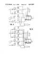
- FIG. 5is a schematic diagram of the control system for the first embodiment of the invention.
- FIG. 6is a schematic diagram of the control system for the second embodiment of the invention.
- FIGS. 1 and 2show a first embodiment of the flame generator 1, which comprises a generator combustion block 2.
- a water cooling jacket 3surrounds the generator combustion block 2, and has a water inlet 4 and outlet 5 located next to each other, and a dividing plate 6 between the inlet 4 and the outlet 5 to cause the cooling water to circulate around the combustion block 2.
- An oxygen conduit 7connects to the oxygen channel 8 through the combustion block 2 for introducing oxygen into the conical combustion chamber 9 of the combustion block.
- a fluid fuel conduit 10provides fluid fuel to a plurality of fuel channels 11 through the combustion block 2, said channels spaced symmetrically around the oxygen channel 8, and preferably angled to direct the fuel to a point in the center of the combustion block within the combustion zone 9.
- an air supply conduit 12provides air to a plurality of air channels 13 through the combustion block 2.
- the air channels 13are symmetrically spaced radially outward from the fuel channels 11, with openings 14 on the conical face of the combustion zone 9.
- gas introduced through openings 14will serve to protect the wall of the combustion chamber from the high temperature combustion product by creating a thin gas film between the wall and the combustion product.
- the combustion block 2may be further cooled by the passing of cool air through the air channels 13 and cool fuel through the fuel channels 11 as they are introduced into the combustion chamber 9.
- a slot 15is provided to the cooling jacket 3 for evacuation of air and steam bubbles.
- Flange 16provides a means for fixing the flame generator to a furnace.
- FIGS. 3 and 4show a second embodiment of a flame generator 20. Similar to the previous embodiment, this embodiment includes a combustion block 21, a water cooling jacket 22 with water inlet 23, water outlet 24, dividing plate 25, and evacuating slot 26. Additionally, the fuel conduit 27, fuel channels 28, air conduit 29 and air channels 30 are similar to the previous embodiment.
- a first oxygen conduit 31connects to a channel 32 through the combustion block 21 along its center line, with a converging-diverging nozzle 33 for directing a supersonic jet of oxygen to a product being heated.
- a second oxygen conduit 34is connected to channels 35 through the combustion block 21 parallel to its center line and spaced radially between channel 32 and channels 28, for delivering a subsonic jet of oxygen to the combustion chamber 36.
- FIG. 5shows the control system for the first embodiment of the flame generator.
- cooling wateris supplied from a water supply line to water inlet 4 then around the combustion block 2 inside the water jacket 3 and escapes through outlet 5.
- the required cooling rateis controlled by thermocouple 63 and pressure gauge 64.
- said blockis made of copper or other material with very high thermal conductivity.
- fuelis delivered from fuel supplying line 58 through valve 59, flowmeter 60 and controlling valve 61 to the flame generator 1 and then through fuel conduit 10 and the plurality of fuel channels 11 into combustion chamber 9.
- the oxidizeris delivered into combustion chamber 9 by different ways depending on whether the process is in the stage of heating, melting or superheating. When the temperature of the material being heated is relatively low, the ratio of air/oxygen will be relatively high and an air jet is delivered from blower 55, through flow meter 56, controlling valve 57, air conduit 12 and the plurality of air channels 13 into combustion chamber 9.
- an oxygen jetcan be delivered from oxygen line 48 into combustion chamber 9 by one or both of the following two ways: first, through valve 49, flowmeter 50, controlling valve 51, oxygen conduit 7 and oxygen channel 8; and second, through valve 52, flowmeter 53, controlling valve 54, air conduit 12, and the plurality of air channels 13.
- An automatic control device 62controls the various supplies of oxygen, air and fuel based on the input from the various pressure and temperature gauges or sensors, and further based on the type of material being heated, the temperature within the furnace, or the stage of the process as determined by a timer in the control device.
- the control device 62is a micro-processor which can be programmed to control various processes as applied to various materials.
- a jet of excess oxygenwill be directed through oxygen conduit 7 and oxygen channel 8, through the center of the flame filling the combustion chamber 9, toward the hot product for the generation of oxidation reactions.
- the oxygen jetcan be blown through converging-diverging nozzle 17 of oxygen channel 8 with supersonic velocity. This will also reduce dilution of oxygen with the combustion product and the furnace atmosphere.
- a jet of excess oxygencan also be directed through the flame filling the combustion chamber 9 toward molten material for refining or other purposes.
- the velocity of this excess oxygen jetcan be increased above sonic to improve the ability of the jet to penetrate into the molten material.
- a fuel-air, fuel-oxygen, or fuel-air-oxygen flamecan be directed at the molten material to heat the material about and inside the oxidation zone.
- the operation of the flame generator 20includes all the steps described above for the first embodiment of the flame generator.
- oxygenmay be delivered in the central zone of the combustion chamber 36 with velocity above sonic through oxygen conduit 31 with converging-diverging nozzle 33, while also being delivered with subsonic velocity through the plurality of oxygen channels 35.
- the positioning of the plurality of oxygen jets delivered by channels 35will separate the central jet of oxygen from the combustion products formed inside combustion chamber 36 by the combustion of fuel with air and oxygen delivered through conduits 27, 29 and 34, respectively. This option increases the flexibility of the flame generator to vary the properties of the flame and the excess oxygen jet directed through the central portion of the combustion chamber.
- FIG. 6The control system for this embodiment is shown in FIG. 6. It is essentially the same as FIG. 5, except for the addition of a supply line with valve 69, flowmeter 70, and controlling valve 71 to oxygen conduit 34.
- the heat input, flame velocity, temperature, luminosity, shape of the flame envelope and the chemistry of the combustion productare controlled continuously by variation of the supply of fuel, air, and oxygen and also by variation of the ways these components are introduced into the combustion chamber, in order to satisfy the heating requirements with minimum operating cost.
- the amount of heat input from a burneris directly related to the amount of hydrocarbon fuel delivered into the burner.
- the invented process or apparatusprovides oxygen to the combustion process either as pure oxygen or as air or a mixture of both. By controlling the ratio of fuel/total oxygen provided to the combustion process, the stoichiometric ratio at which complete combustion of the oxygen and fuel occurs, may be maintained as desired to efficiently utilize the substance introduced into the burner.
- the temperature of the flamemay be increased by causing the oxidizing gas to have a higher oxygen concentration. This is accomplished by varying the air and pure oxygen supplied to the burner to control the air/total oxygen ratio. Although supplying pure oxygen is clearly more expensive than the use of air, at some point in a process the higher flame temperature may be desirable to more efficiently transfer heat to the product.
- a highly emissive flamecomes from the conversion of excess atomic carbon from the hydrocarbon fuel into highly emissive molecular carbon inside the core of the flame. This is accomplished in the present invention by providing a small amount (10-30 percent) of oxygen in the core of the flame relative to the oxygen provided to the outer part of the flame. Therefore, by controlling the ratio of hydrocarbon fuel/oxygen in the center of the flame while maintaining all other parameters at the desired values, the emissivity of the flame may be controlled.
- NOxmay be reduced by controlling and maximizing the ratio of air introduced to the outside of the flame/air introduced to the center of the flame, for any given total air content to be introduced into the combustion chamber.
- the burner described hereinmay utilize preheated air or a preheated air-oxygen mixture as an oxidizing gas. This may allow recovery of waste heat from the process to provide the preheated air or a preheated air-oxygen mixture and make the operation more efficient.
- preheated air or a preheated air-oxygen mixturemay be utilized as an oxidizing gas. This may allow recovery of waste heat from the process to provide the preheated air or a preheated air-oxygen mixture and make the operation more efficient.
- the hot gasBy providing the hot gas under pressure and designing the channels to have a relatively small surface area, the hot gas will not be significantly cooled by the cooling of the combustion block nor will the hot gas interfere with the cooling of the combustion block.
Landscapes
- Engineering & Computer Science (AREA)
- Chemical & Material Sciences (AREA)
- Mechanical Engineering (AREA)
- General Engineering & Computer Science (AREA)
- Combustion & Propulsion (AREA)
- Environmental & Geological Engineering (AREA)
- Materials Engineering (AREA)
- Organic Chemistry (AREA)
- Nozzles (AREA)
Abstract
Description
Claims (44)
Priority Applications (17)
| Application Number | Priority Date | Filing Date | Title |
|---|---|---|---|
| US06/642,141US4622007A (en) | 1984-08-17 | 1984-08-17 | Variable heat generating method and apparatus |
| US06/755,831US4642047A (en) | 1984-08-17 | 1985-07-15 | Method and apparatus for flame generation and utilization of the combustion products for heating, melting and refining |
| ZA856242AZA856242B (en) | 1984-08-17 | 1985-08-06 | Method and apparatus for flame generation |
| EP19850904202EP0192682B1 (en) | 1984-08-17 | 1985-08-12 | Method and apparatus for flame generation |
| PCT/US1985/001537WO1986001131A1 (en) | 1984-08-17 | 1985-08-12 | Method and apparatus for flame generation |
| JP60503669AJPS62500010A (en) | 1984-08-17 | 1985-08-12 | Flame generation method and device |
| BR8506880ABR8506880A (en) | 1984-08-17 | 1985-08-12 | PROCESS AND APPARATUS FOR GENERATING FLAME |
| AU47267/85AAU588829B2 (en) | 1984-08-17 | 1985-08-12 | Method and apparatus for flame generation |
| AT85904202TATE86147T1 (en) | 1984-08-17 | 1985-08-12 | METHOD AND DEVICE FOR GENERATING FLAME. |
| DE8585904202TDE3587153T2 (en) | 1984-08-17 | 1985-08-12 | METHOD AND DEVICE FOR PRODUCING FLAME. |
| KR1019860700220AKR900006616B1 (en) | 1984-08-17 | 1985-08-12 | Spark generation method and apparatus |
| ES546160AES8800409A1 (en) | 1984-08-17 | 1985-08-14 | Method and apparatus for flame generation. |
| MX20633985AMX162814A (en) | 1984-08-17 | 1985-08-16 | IMPROVEMENTS IN METHOD AND HYDROCARBON FLUID FUEL COMBUSTION BURNER |
| US07/009,145US4861262A (en) | 1984-08-17 | 1987-01-29 | Method and apparatus for waste disposal |
| US07/180,445US4923391A (en) | 1984-08-17 | 1988-04-12 | Regenerative burner |
| US07/306,816USRE33464E (en) | 1984-08-17 | 1989-02-03 | Method and apparatus for flame generation and utilization of the combustion products for heating, melting and refining |
| US07/751,864USRE34298E (en) | 1984-08-17 | 1991-08-28 | Method for waste disposal |
Applications Claiming Priority (1)
| Application Number | Priority Date | Filing Date | Title |
|---|---|---|---|
| US06/642,141US4622007A (en) | 1984-08-17 | 1984-08-17 | Variable heat generating method and apparatus |
Related Child Applications (2)
| Application Number | Title | Priority Date | Filing Date |
|---|---|---|---|
| US06/755,831Continuation-In-PartUS4642047A (en) | 1984-08-17 | 1985-07-15 | Method and apparatus for flame generation and utilization of the combustion products for heating, melting and refining |
| US07/306,816Continuation-In-PartUSRE33464E (en) | 1984-08-17 | 1989-02-03 | Method and apparatus for flame generation and utilization of the combustion products for heating, melting and refining |
Publications (1)
| Publication Number | Publication Date |
|---|---|
| US4622007Atrue US4622007A (en) | 1986-11-11 |
Family
ID=24575371
Family Applications (2)
| Application Number | Title | Priority Date | Filing Date |
|---|---|---|---|
| US06/642,141Expired - LifetimeUS4622007A (en) | 1984-08-17 | 1984-08-17 | Variable heat generating method and apparatus |
| US07/306,816Expired - LifetimeUSRE33464E (en) | 1984-08-17 | 1989-02-03 | Method and apparatus for flame generation and utilization of the combustion products for heating, melting and refining |
Family Applications After (1)
| Application Number | Title | Priority Date | Filing Date |
|---|---|---|---|
| US07/306,816Expired - LifetimeUSRE33464E (en) | 1984-08-17 | 1989-02-03 | Method and apparatus for flame generation and utilization of the combustion products for heating, melting and refining |
Country Status (3)
| Country | Link |
|---|---|
| US (2) | US4622007A (en) |
| JP (1) | JPS62500010A (en) |
| ZA (1) | ZA856242B (en) |
Cited By (128)
| Publication number | Priority date | Publication date | Assignee | Title |
|---|---|---|---|---|
| US4878829A (en)* | 1988-05-05 | 1989-11-07 | Union Carbide Corporation | Fuel jet burner and combustion method |
| US4907961A (en)* | 1988-05-05 | 1990-03-13 | Union Carbide Corporation | Oxygen jet burner and combustion method |
| US4969814A (en)* | 1989-05-08 | 1990-11-13 | Union Carbide Corporation | Multiple oxidant jet combustion method and apparatus |
| US5000102A (en)* | 1989-12-21 | 1991-03-19 | Union Carbide Industrial Gases Technology Corporation | Method for combusting wet waste |
| US5006141A (en)* | 1990-01-30 | 1991-04-09 | Air Products And Chemicals, Inc. | Thermally efficient melting for glass making |
| WO1991010105A1 (en)* | 1990-01-02 | 1991-07-11 | American Combustion, Inc. | Flash smelting furnace |
| US5057133A (en)* | 1990-07-02 | 1991-10-15 | Air Products And Chemicals, Inc. | Thermally efficient melting and fuel reforming for glass making |
| US5062789A (en)* | 1988-06-08 | 1991-11-05 | Gitman Gregory M | Aspirating combustion system |
| US5108729A (en)* | 1989-10-02 | 1992-04-28 | Phillips Petroleum Company | Production of carbide products |
| EP0419463A4 (en)* | 1988-06-17 | 1992-08-19 | American Combustion, Inc. | A method and apparatus for waste disposal |
| US5165916A (en)* | 1989-10-02 | 1992-11-24 | Phillips Petroleum Company | Method for producing carbide products |
| US5174746A (en)* | 1990-05-11 | 1992-12-29 | Sumitomo Metal Mining Company Limited | Method of operation of flash smelting furnace |
| AU644350B2 (en)* | 1988-09-02 | 1993-12-09 | American Combustion, Incorporated | Method and apparatus for generating highly luminous flame |
| US5413476A (en)* | 1993-04-13 | 1995-05-09 | Gas Research Institute | Reduction of nitrogen oxides in oxygen-enriched combustion processes |
| US5427524A (en)* | 1993-06-07 | 1995-06-27 | Gas Research Institute | Natural gas fired rich burn combustor |
| US5439373A (en)* | 1993-09-13 | 1995-08-08 | Praxair Technology, Inc. | Luminous combustion system |
| US5454712A (en)* | 1993-09-15 | 1995-10-03 | The Boc Group, Inc. | Air-oxy-fuel burner method and apparatus |
| WO1996006954A1 (en)* | 1994-08-29 | 1996-03-07 | American Combustion, Incorporated | Method and apparatus for electric steelmaking |
| US5511728A (en)* | 1994-06-02 | 1996-04-30 | The Babcock & Wilcox Company | Dual fluid atomizer for high solids soil paste containing pebbles or agglomerates |
| US5554022A (en)* | 1994-10-14 | 1996-09-10 | Xothermic, Inc. | Burner apparatus and method |
| US5611683A (en)* | 1995-08-04 | 1997-03-18 | Air Products And Chemicals, Inc. | Method and apparatus for reducing NOX production during air-oxygen-fuel combustion |
| US5681162A (en)* | 1996-09-23 | 1997-10-28 | Nabors, Jr.; James K. | Low pressure atomizer |
| WO1997044618A1 (en) | 1996-05-17 | 1997-11-27 | Xothermic, Inc. | Burner apparatus and method |
| US5714113A (en)* | 1994-08-29 | 1998-02-03 | American Combustion, Inc. | Apparatus for electric steelmaking |
| EP0866140A1 (en)* | 1997-03-18 | 1998-09-23 | Praxair Technology, Inc. | Coherent gas jet |
| EP0866139A1 (en)* | 1997-03-18 | 1998-09-23 | Praxair Technology, Inc. | Lance/burner for molten metal furnace |
| US5904475A (en)* | 1997-05-08 | 1999-05-18 | Praxair Technology, Inc. | Dual oxidant combustion system |
| EP0918093A1 (en)* | 1997-11-20 | 1999-05-26 | Praxair Technology, Inc. | Coherent jet injector lance |
| US5927960A (en)* | 1995-09-21 | 1999-07-27 | The Boc Group Plc | Burner |
| US5944507A (en)* | 1997-05-07 | 1999-08-31 | The Boc Group Plc | Oxy/oil swirl burner |
| US6109062A (en)* | 1996-10-08 | 2000-08-29 | Richards; Raymond S. | Apparatus for melting molten material |
| WO2000043712A3 (en)* | 1999-01-22 | 2000-09-28 | Clean Energy Systems Inc | Steam generator injector |
| US6139310A (en)* | 1999-11-16 | 2000-10-31 | Praxair Technology, Inc. | System for producing a single coherent jet |
| US6142765A (en)* | 1995-09-07 | 2000-11-07 | Vost-Alpine Industrieanlagenbau Gmbh | Process for burning fuel |
| US6176894B1 (en) | 1998-06-17 | 2001-01-23 | Praxair Technology, Inc. | Supersonic coherent gas jet for providing gas into a liquid |
| US6200128B1 (en)* | 1997-06-09 | 2001-03-13 | Praxair Technology, Inc. | Method and apparatus for recovering sensible heat from a hot exhaust gas |
| US6241510B1 (en) | 2000-02-02 | 2001-06-05 | Praxair Technology, Inc. | System for providing proximate turbulent and coherent gas jets |
| US6244860B1 (en)* | 1998-11-25 | 2001-06-12 | Messer Griesheim Gmbh | Apparatus and process for producing perlite |
| US6247316B1 (en) | 2000-03-22 | 2001-06-19 | Clean Energy Systems, Inc. | Clean air engines for transportation and other power applications |
| US6334976B1 (en) | 2000-08-03 | 2002-01-01 | Praxair Technology, Inc. | Fluid cooled coherent jet lance |
| FR2816524A1 (en)* | 2000-11-15 | 2002-05-17 | Air Liquide | Installation for the manual flame assisted spray coating of components incorporating a safety trigger and control system to cut the flame in emergency situations |
| US6389814B2 (en) | 1995-06-07 | 2002-05-21 | Clean Energy Systems, Inc. | Hydrocarbon combustion power generation system with CO2 sequestration |
| US6400747B1 (en) | 2001-05-18 | 2002-06-04 | Praxair Technology, Inc. | Quadrilateral assembly for coherent jet lancing and post combustion in an electric arc furnace |
| US6432163B1 (en) | 2001-06-22 | 2002-08-13 | Praxair Technology, Inc. | Metal refining method using differing refining oxygen sequence |
| US6439140B2 (en)* | 1996-12-27 | 2002-08-27 | Sumitomo Osaka Cement Co., Ltd. | Device and method for combustion of fuel |
| US6450799B1 (en) | 2001-12-04 | 2002-09-17 | Praxair Technology, Inc. | Coherent jet system using liquid fuel flame shroud |
| FR2823290A1 (en) | 2001-04-06 | 2002-10-11 | Air Liquide | COMBUSTION PROCESS INCLUDING SEPARATE INJECTIONS OF FUEL AND OXIDIZING AND BURNER ASSEMBLY FOR IMPLEMENTATION OF THIS PROCESS |
| US20030129555A1 (en)* | 2001-12-25 | 2003-07-10 | Yuji Mukai | Burner for hydrogen generation system and hydrogen generation system having the same |
| US6604937B1 (en) | 2002-05-24 | 2003-08-12 | Praxair Technology, Inc. | Coherent jet system with single ring flame envelope |
| US6622470B2 (en) | 2000-05-12 | 2003-09-23 | Clean Energy Systems, Inc. | Semi-closed brayton cycle gas turbine power systems |
| EP1035221A3 (en)* | 1999-03-05 | 2003-11-19 | Linde AG | Burner, shaft furnace and shaft furnace operating method |
| US6663381B2 (en)* | 2001-09-20 | 2003-12-16 | Carrier Corporation | Burner arrangement for low NOX emissions |
| US20040000747A1 (en)* | 2002-06-26 | 2004-01-01 | Mahoney William John | Extensionless coherent jet system with aligned flame envelope ports |
| US20040000789A1 (en)* | 2002-06-27 | 2004-01-01 | Nanya Technology Corporation | Piping apparatus |
| EP1160007A3 (en)* | 2000-05-31 | 2004-01-07 | Messer Griesheim GmbH | Apparatus and process for expanding vermiculite |
| US20040135296A1 (en)* | 2003-01-15 | 2004-07-15 | Mahoney William John | Coherent jet system with outwardly angled flame envelope ports |
| US20040172976A1 (en)* | 2002-12-25 | 2004-09-09 | Yoshiaki Shimizu | Method for processing a preform for optical fiber, burner system useful for carrying out the method and apparatus comprising the burner system |
| US20040174920A1 (en)* | 2002-12-19 | 2004-09-09 | Alex Popenov | Method and apparatus for spatial energy coverage |
| US20040175323A1 (en)* | 2003-03-05 | 2004-09-09 | Marcus Franz | Process and apparatus for preparing hydrogen chloride |
| US20040191710A1 (en)* | 2002-11-14 | 2004-09-30 | Velke William H. | Fuel density reduction method and device to improve the ratio of oxygen mass versus fuel mass during ignition in combustion mechanisms operating with fluid hydrocarbon fuels |
| RU2239139C2 (en)* | 1999-04-02 | 2004-10-27 | Праксайр Текнолоджи, Инк. | Method of obtaining many coherent gas jets at use of single tuyere (versions) and tuyere used for realization of this method |
| US20040261676A1 (en)* | 2003-06-09 | 2004-12-30 | Choi Donald H | Utilization of exhaust heat for conversion of water to fuel |
| US6868677B2 (en) | 2001-05-24 | 2005-03-22 | Clean Energy Systems, Inc. | Combined fuel cell and fuel combustion power generation systems |
| US20050086724A1 (en)* | 2003-10-25 | 2005-04-28 | Marsh M. L. | Practical souvenir competition hats |
| US6945029B2 (en) | 2002-11-15 | 2005-09-20 | Clean Energy Systems, Inc. | Low pollution power generation system with ion transfer membrane air separation |
| US20050241339A1 (en)* | 2002-05-28 | 2005-11-03 | Scott Garrett L | Method and apparatus for lubricating molten glass forming molds |
| US20060063118A1 (en)* | 2002-12-19 | 2006-03-23 | Yamaichi Metal Co., Ltd. | Animal and vegetable oil combustor |
| US7021063B2 (en) | 2003-03-10 | 2006-04-04 | Clean Energy Systems, Inc. | Reheat heat exchanger power generation systems |
| US20070003889A1 (en)* | 2005-06-30 | 2007-01-04 | Larue Albert D | Burner with center air jet |
| US20070044479A1 (en)* | 2005-08-10 | 2007-03-01 | Harry Brandt | Hydrogen production from an oxyfuel combustor |
| US20070231761A1 (en)* | 2006-04-03 | 2007-10-04 | Lee Rosen | Integration of oxy-fuel and air-fuel combustion |
| US20070254251A1 (en)* | 2006-04-26 | 2007-11-01 | Jin Cao | Ultra-low NOx burner assembly |
| US20070254254A1 (en)* | 2006-05-01 | 2007-11-01 | Gehring Michael W | Conical cyclonic oxidizing burner |
| US20070267787A1 (en)* | 2006-05-17 | 2007-11-22 | Higgins Christopher K | Methods of implementing a water-cooling system into a burner panel and related apparatuses |
| US20070267786A1 (en)* | 2006-05-17 | 2007-11-22 | Higgins Christopher K | Methods of implementing a water-cooling system into a burner panel and related apparatuses |
| US20080000325A1 (en)* | 2006-06-28 | 2008-01-03 | William John Mahoney | Oxygen injection method |
| US20090230209A1 (en)* | 2005-12-09 | 2009-09-17 | Utah State University | Directional jet flow control |
| US20100044930A1 (en)* | 2006-12-15 | 2010-02-25 | Praxair Technology Inc. | Injection method for inert gas |
| US20100252968A1 (en)* | 2009-04-02 | 2010-10-07 | Glass Joshua W | Forged Copper Burner Enclosure |
| US7882692B2 (en) | 2004-04-16 | 2011-02-08 | Clean Energy Systems, Inc. | Zero emissions closed rankine cycle power system |
| US20110061642A1 (en)* | 2008-02-05 | 2011-03-17 | Saint-Gobain Glass France | Low-nox gas injector |
| US20110265715A1 (en)* | 2010-04-29 | 2011-11-03 | Amt Ag | Device for Coating Substrates by Means of High-Velocity Flame Spraying |
| EP2495519A1 (en) | 2011-03-01 | 2012-09-05 | L'Air Liquide Société Anonyme pour l'Etude et l'Exploitation des Procédés Georges Claude | Method of installing a burner and/or injector panel apparatus and method of treating metal using the same |
| US20120301835A1 (en)* | 2010-12-01 | 2012-11-29 | Martin Adendorff | Method and device for diluted combustion |
| US20130016754A1 (en)* | 2010-02-18 | 2013-01-17 | Sms Siemag Aktiengesellschaft | Injector cooling block for holding at least one injector |
| US20130086951A1 (en)* | 2010-06-17 | 2013-04-11 | Mark William Charbonneau | Systems and methods for glass manufacturing |
| US20130269577A1 (en)* | 2003-04-04 | 2013-10-17 | Honeywell International Inc. | Apparatus for burning pulverized solid fuels with oxygen |
| EP2746657A1 (en)* | 2012-12-19 | 2014-06-25 | L'air Liquide, Societe Anonyme Pour L'etude Et L'exploitation Des Procedes Georges Claude | Method for combusting fuel and burner therefor |
| WO2014189501A1 (en)* | 2013-05-22 | 2014-11-27 | Johns Manville | Submerged combustion burners, melters, and methods of use |
| CN104197325A (en)* | 2014-08-28 | 2014-12-10 | 唐山金沙燃烧热能科技有限公司 | Pulverized coal combustion way |
| WO2015014919A1 (en)* | 2013-07-31 | 2015-02-05 | Knauf Insulation | Melter having a submerged combustion burner, method using the burner and use of the burner |
| WO2016162600A1 (en)* | 2015-04-10 | 2016-10-13 | Nordautomation Oy | Arrangement in rotary kiln and method for guiding air to said rotary kiln |
| US9676644B2 (en) | 2012-11-29 | 2017-06-13 | Johns Manville | Methods and systems for making well-fined glass using submerged combustion |
| US9731990B2 (en) | 2013-05-30 | 2017-08-15 | Johns Manville | Submerged combustion glass melting systems and methods of use |
| US9751792B2 (en) | 2015-08-12 | 2017-09-05 | Johns Manville | Post-manufacturing processes for submerged combustion burner |
| US9777922B2 (en) | 2013-05-22 | 2017-10-03 | Johns Mansville | Submerged combustion burners and melters, and methods of use |
| US9815726B2 (en) | 2015-09-03 | 2017-11-14 | Johns Manville | Apparatus, systems, and methods for pre-heating feedstock to a melter using melter exhaust |
| US9878932B2 (en) | 2013-07-31 | 2018-01-30 | Knauf Insulation | Submerged combustion melters and methods |
| US20180038590A1 (en)* | 2015-02-27 | 2018-02-08 | Taiyo Nippon Sanso Corporation | Gas fuel burner and method for heating with gas fuel burner |
| US9926219B2 (en) | 2012-07-03 | 2018-03-27 | Johns Manville | Process of using a submerged combustion melter to produce hollow glass fiber or solid glass fiber having entrained bubbles, and burners and systems to make such fibers |
| US9957184B2 (en) | 2011-10-07 | 2018-05-01 | Johns Manville | Submerged combustion glass manufacturing system and method |
| US9982884B2 (en) | 2015-09-15 | 2018-05-29 | Johns Manville | Methods of melting feedstock using a submerged combustion melter |
| US20180170786A1 (en)* | 2015-06-02 | 2018-06-21 | Verallia France | Sonic injection furnace |
| US10041666B2 (en) | 2015-08-27 | 2018-08-07 | Johns Manville | Burner panels including dry-tip burners, submerged combustion melters, and methods |
| US10081565B2 (en) | 2010-06-17 | 2018-09-25 | Johns Manville | Systems and methods for making foamed glass using submerged combustion |
| US10081563B2 (en) | 2015-09-23 | 2018-09-25 | Johns Manville | Systems and methods for mechanically binding loose scrap |
| US10131563B2 (en) | 2013-05-22 | 2018-11-20 | Johns Manville | Submerged combustion burners |
| US10138151B2 (en) | 2013-05-22 | 2018-11-27 | Johns Manville | Submerged combustion burners and melters, and methods of use |
| US10144666B2 (en) | 2015-10-20 | 2018-12-04 | Johns Manville | Processing organics and inorganics in a submerged combustion melter |
| US10183884B2 (en) | 2013-05-30 | 2019-01-22 | Johns Manville | Submerged combustion burners, submerged combustion glass melters including the burners, and methods of use |
| US10196294B2 (en) | 2016-09-07 | 2019-02-05 | Johns Manville | Submerged combustion melters, wall structures or panels of same, and methods of using same |
| US10233105B2 (en) | 2016-10-14 | 2019-03-19 | Johns Manville | Submerged combustion melters and methods of feeding particulate material into such melters |
| US10246362B2 (en) | 2016-06-22 | 2019-04-02 | Johns Manville | Effective discharge of exhaust from submerged combustion melters and methods |
| US10301208B2 (en) | 2016-08-25 | 2019-05-28 | Johns Manville | Continuous flow submerged combustion melter cooling wall panels, submerged combustion melters, and methods of using same |
| US10322960B2 (en) | 2010-06-17 | 2019-06-18 | Johns Manville | Controlling foam in apparatus downstream of a melter by adjustment of alkali oxide content in the melter |
| US10337732B2 (en) | 2016-08-25 | 2019-07-02 | Johns Manville | Consumable tip burners, submerged combustion melters including same, and methods |
| US10336640B2 (en) | 2013-07-31 | 2019-07-02 | Knauf Insulation | Method and apparatus for melting solid raw batch material using submerged combustion burners |
| US10392285B2 (en) | 2012-10-03 | 2019-08-27 | Johns Manville | Submerged combustion melters having an extended treatment zone and methods of producing molten glass |
| US10494286B2 (en) | 2013-07-31 | 2019-12-03 | Knauf Insulation | Process for manufacturing vitrified material by melting |
| US20200148571A1 (en)* | 2017-07-21 | 2020-05-14 | Engie | Method of melting raw materials such as glass by a cross-fired melting furnace |
| US10670261B2 (en) | 2015-08-27 | 2020-06-02 | Johns Manville | Burner panels, submerged combustion melters, and methods |
| US20200255315A1 (en)* | 2016-06-22 | 2020-08-13 | Jushi Group Co., Ltd. | Glass tank furnace and glass melting method |
| US10837705B2 (en) | 2015-09-16 | 2020-11-17 | Johns Manville | Change-out system for submerged combustion melting burner |
| US10858278B2 (en) | 2013-07-18 | 2020-12-08 | Johns Manville | Combustion burner |
| US20210122081A1 (en)* | 2019-10-29 | 2021-04-29 | Fundacion Tecnalia Research & Innovation | High velocity oxy air fuel thermal spray apparatus |
| US11142476B2 (en) | 2013-05-22 | 2021-10-12 | Johns Manville | Burner for submerged combustion melting |
| US20220003407A1 (en)* | 2020-07-01 | 2022-01-06 | Messer Industries Usa, Inc. | Burner, furnace and method of generating a flame |
| US11613488B2 (en) | 2012-10-03 | 2023-03-28 | Johns Manville | Methods and systems for destabilizing foam in equipment downstream of a submerged combustion melter |
Families Citing this family (29)
| Publication number | Priority date | Publication date | Assignee | Title |
|---|---|---|---|---|
| US5477685A (en)* | 1993-11-12 | 1995-12-26 | The Regents Of The University Of California | Lean burn injector for gas turbine combustor |
| AUPN226095A0 (en) | 1995-04-07 | 1995-05-04 | Technological Resources Pty Limited | A method of producing metals and metal alloys |
| AUPO426096A0 (en) | 1996-12-18 | 1997-01-23 | Technological Resources Pty Limited | Method and apparatus for producing metals and metal alloys |
| AUPO426396A0 (en) | 1996-12-18 | 1997-01-23 | Technological Resources Pty Limited | A method of producing iron |
| AUPO944697A0 (en) | 1997-09-26 | 1997-10-16 | Technological Resources Pty Limited | A method of producing metals and metal alloys |
| AUPP442598A0 (en) | 1998-07-01 | 1998-07-23 | Technological Resources Pty Limited | Direct smelting vessel |
| AUPP483898A0 (en) | 1998-07-24 | 1998-08-13 | Technological Resources Pty Limited | A direct smelting process & apparatus |
| MY119760A (en) | 1998-07-24 | 2005-07-29 | Tech Resources Pty Ltd | A direct smelting process |
| AUPP554098A0 (en) | 1998-08-28 | 1998-09-17 | Technological Resources Pty Limited | A process and an apparatus for producing metals and metal alloys |
| AUPP570098A0 (en) | 1998-09-04 | 1998-10-01 | Technological Resources Pty Limited | A direct smelting process |
| AUPP647198A0 (en) | 1998-10-14 | 1998-11-05 | Technological Resources Pty Limited | A process and an apparatus for producing metals and metal alloys |
| AUPP805599A0 (en) | 1999-01-08 | 1999-02-04 | Technological Resources Pty Limited | A direct smelting process |
| US6312250B1 (en)* | 1999-04-19 | 2001-11-06 | North American Manufacturing Company | Premix burner with firing rate control |
| AUPQ083599A0 (en) | 1999-06-08 | 1999-07-01 | Technological Resources Pty Limited | Direct smelting vessel |
| AUPQ152299A0 (en) | 1999-07-09 | 1999-08-05 | Technological Resources Pty Limited | Start-up procedure for direct smelting process |
| AUPQ205799A0 (en) | 1999-08-05 | 1999-08-26 | Technological Resources Pty Limited | A direct smelting process |
| AUPQ213099A0 (en) | 1999-08-10 | 1999-09-02 | Technological Resources Pty Limited | Pressure control |
| AUPQ308799A0 (en) | 1999-09-27 | 1999-10-21 | Technological Resources Pty Limited | A direct smelting process |
| AUPQ346399A0 (en) | 1999-10-15 | 1999-11-11 | Technological Resources Pty Limited | Stable idle procedure |
| AUPQ365799A0 (en) | 1999-10-26 | 1999-11-18 | Technological Resources Pty Limited | A direct smelting apparatus and process |
| US6602321B2 (en) | 2000-09-26 | 2003-08-05 | Technological Resources Pty. Ltd. | Direct smelting process |
| US20060127831A1 (en)* | 2004-12-13 | 2006-06-15 | Kagi Thomas Sr | Waste oil multi-fuel fired burner |
| GB0803959D0 (en) | 2008-03-03 | 2008-04-09 | Pursuit Dynamics Plc | An improved mist generating apparatus |
| EP2231204B1 (en)* | 2007-11-09 | 2017-10-18 | Tyco Fire & Security GmbH | Improvements in or relating to decontamination |
| SI2262915T1 (en)* | 2008-03-28 | 2018-11-30 | L'air Liquide Societe Anonyme Pour L'etude Et L'exploitation Des Procedes Georges Claude | Burner/injector panel apparatus |
| US8478446B2 (en)* | 2008-06-13 | 2013-07-02 | Air Products And Chemicals, Inc. | Oxygen control system for oxygen enhanced combustion |
| US8578892B2 (en)* | 2008-06-13 | 2013-11-12 | Air Products And Chemicals, Inc. | Oxygen control system for oxygen enhanced combustion of solid fuels |
| US8827176B2 (en)* | 2012-07-05 | 2014-09-09 | James A. Browning | HVOF torch with fuel surrounding oxidizer |
| JP7139298B2 (en)* | 2019-09-27 | 2022-09-20 | 大陽日酸株式会社 | High-temperature oxygen generator and high-temperature oxygen generation method |
Citations (24)
| Publication number | Priority date | Publication date | Assignee | Title |
|---|---|---|---|---|
| SU188221A1 (en)* | В. С. Омиров, Р. М. Кривов А. С. Штейнберг, В. Н. Маркочев | COMBUSTION CHAMBER OF A GAS TURBINE ENGINE | ||
| US2368370A (en)* | 1943-05-26 | 1945-01-30 | Maxon Premix Burner Company | Gas burner |
| US2398884A (en)* | 1943-12-15 | 1946-04-23 | Air Reduction | Gas torch |
| US2458543A (en)* | 1945-04-24 | 1949-01-11 | Comb Processes Company | Low velocity gas burner |
| US2655986A (en)* | 1950-08-23 | 1953-10-20 | Inland Steel Co | Burner of the projected flame type |
| US3092166A (en)* | 1959-12-15 | 1963-06-04 | Air Reduction | Space heating method and apparatus |
| US3208502A (en)* | 1961-03-08 | 1965-09-28 | Babcock & Wilcox Ltd | Fuel burners having air control means |
| US3266552A (en)* | 1959-02-21 | 1966-08-16 | Siderurgie Fse Inst Rech | Burner for producing a stable flame with a high concentration of heat stabilized by a shock wave |
| US3418062A (en)* | 1966-08-08 | 1968-12-24 | Bloom Eng Co Inc | Burner structures |
| US3455514A (en)* | 1967-11-09 | 1969-07-15 | Dow Chemical Co | Metal removing torch tip |
| US3545903A (en)* | 1969-03-12 | 1970-12-08 | United States Steel Corp | Burner for preheating a refractory lined vessel |
| US3563683A (en)* | 1969-04-03 | 1971-02-16 | Selas Corp Of America | Industrial burner |
| US3612738A (en)* | 1970-01-12 | 1971-10-12 | Air Prod & Chem | Metallurgical burner |
| US3729285A (en)* | 1972-05-22 | 1973-04-24 | G Schwedersky | Burner and method of operating it to control the production of nitrogen oxides |
| US3748082A (en)* | 1970-06-01 | 1973-07-24 | Air Liquide Sa Etude Exploit P | Method for cracking and burning hydrocarbons |
| US3856457A (en)* | 1972-12-29 | 1974-12-24 | Air Prod & Chem | Burner of the oxy-fuel type |
| US3889933A (en)* | 1974-02-28 | 1975-06-17 | Int Nickel Canada | Metallurgical lance |
| US4017253A (en)* | 1975-09-16 | 1977-04-12 | The United States Of America As Represented By The United States Energy Research And Development Administration | Fluidized-bed calciner with combustion nozzle and shroud |
| SU635361A1 (en)* | 1977-04-20 | 1978-11-30 | Сибирский Металлургический Институт Имени С.Орджоникидзе | Burner |
| US4173499A (en)* | 1976-07-27 | 1979-11-06 | Linde Aktiengesellschaft | Method of operating a cutting burner |
| US4342551A (en)* | 1980-05-23 | 1982-08-03 | Browning Engineering Corporation | Ignition method and system for internal burner type ultra-high velocity flame jet apparatus |
| US4422624A (en)* | 1981-08-27 | 1983-12-27 | Phelps Dodge Corporation | Concentrate burner |
| US4473350A (en)* | 1982-06-24 | 1984-09-25 | The Cadre Corporation | Oxy-fuel burner |
| US4475885A (en)* | 1983-07-28 | 1984-10-09 | Bloom Engineering Company, Inc. | Adjustable flame burner |
Family Cites Families (12)
| Publication number | Priority date | Publication date | Assignee | Title |
|---|---|---|---|---|
| US3127156A (en)* | 1964-03-31 | Figure | ||
| US1721381A (en)* | 1928-02-02 | 1929-07-16 | Gen Electric | Gas burner |
| US3216714A (en)* | 1963-02-04 | 1965-11-09 | Bot Brassert Oxygen Technik Ag | Heating and blowing device for metallurgical purposes |
| US3224486A (en)* | 1964-12-07 | 1965-12-21 | Lorant B Geller | Method and apparatus for producing air-fuel flames of sonic and supersonic velocities |
| US4021191A (en)* | 1972-10-30 | 1977-05-03 | Aqua-Chem, Inc. | Reduction of pollutants in gaseous hydrocarbon combustion products |
| US3880571A (en)* | 1973-07-26 | 1975-04-29 | Trw Inc | Burner assembly for providing reduced emission of air pollutant |
| US4278418A (en)* | 1975-12-15 | 1981-07-14 | Strenkert Lynn A | Process and apparatus for stoichiometric combustion of fuel oil |
| US4541796A (en)* | 1980-04-10 | 1985-09-17 | Union Carbide Corporation | Oxygen aspirator burner for firing a furnace |
| JPS5835224U (en)* | 1981-09-01 | 1983-03-08 | 株式会社明電舎 | butsing |
| JPS5852904A (en)* | 1981-09-21 | 1983-03-29 | Osaka Gas Co Ltd | Method of burning |
| JPS5883128A (en)* | 1981-11-12 | 1983-05-18 | Matsushita Electric Ind Co Ltd | heating cooker |
| US4525175A (en)* | 1983-05-31 | 1985-06-25 | Texaco Inc. | High turn down burner for partial oxidation of slurries of solid fuel |
- 1984
- 1984-08-17USUS06/642,141patent/US4622007A/ennot_activeExpired - Lifetime
- 1985
- 1985-08-06ZAZA856242Apatent/ZA856242B/enunknown
- 1985-08-12JPJP60503669Apatent/JPS62500010A/enactivePending
- 1989
- 1989-02-03USUS07/306,816patent/USRE33464E/ennot_activeExpired - Lifetime
Patent Citations (24)
| Publication number | Priority date | Publication date | Assignee | Title |
|---|---|---|---|---|
| SU188221A1 (en)* | В. С. Омиров, Р. М. Кривов А. С. Штейнберг, В. Н. Маркочев | COMBUSTION CHAMBER OF A GAS TURBINE ENGINE | ||
| US2368370A (en)* | 1943-05-26 | 1945-01-30 | Maxon Premix Burner Company | Gas burner |
| US2398884A (en)* | 1943-12-15 | 1946-04-23 | Air Reduction | Gas torch |
| US2458543A (en)* | 1945-04-24 | 1949-01-11 | Comb Processes Company | Low velocity gas burner |
| US2655986A (en)* | 1950-08-23 | 1953-10-20 | Inland Steel Co | Burner of the projected flame type |
| US3266552A (en)* | 1959-02-21 | 1966-08-16 | Siderurgie Fse Inst Rech | Burner for producing a stable flame with a high concentration of heat stabilized by a shock wave |
| US3092166A (en)* | 1959-12-15 | 1963-06-04 | Air Reduction | Space heating method and apparatus |
| US3208502A (en)* | 1961-03-08 | 1965-09-28 | Babcock & Wilcox Ltd | Fuel burners having air control means |
| US3418062A (en)* | 1966-08-08 | 1968-12-24 | Bloom Eng Co Inc | Burner structures |
| US3455514A (en)* | 1967-11-09 | 1969-07-15 | Dow Chemical Co | Metal removing torch tip |
| US3545903A (en)* | 1969-03-12 | 1970-12-08 | United States Steel Corp | Burner for preheating a refractory lined vessel |
| US3563683A (en)* | 1969-04-03 | 1971-02-16 | Selas Corp Of America | Industrial burner |
| US3612738A (en)* | 1970-01-12 | 1971-10-12 | Air Prod & Chem | Metallurgical burner |
| US3748082A (en)* | 1970-06-01 | 1973-07-24 | Air Liquide Sa Etude Exploit P | Method for cracking and burning hydrocarbons |
| US3729285A (en)* | 1972-05-22 | 1973-04-24 | G Schwedersky | Burner and method of operating it to control the production of nitrogen oxides |
| US3856457A (en)* | 1972-12-29 | 1974-12-24 | Air Prod & Chem | Burner of the oxy-fuel type |
| US3889933A (en)* | 1974-02-28 | 1975-06-17 | Int Nickel Canada | Metallurgical lance |
| US4017253A (en)* | 1975-09-16 | 1977-04-12 | The United States Of America As Represented By The United States Energy Research And Development Administration | Fluidized-bed calciner with combustion nozzle and shroud |
| US4173499A (en)* | 1976-07-27 | 1979-11-06 | Linde Aktiengesellschaft | Method of operating a cutting burner |
| SU635361A1 (en)* | 1977-04-20 | 1978-11-30 | Сибирский Металлургический Институт Имени С.Орджоникидзе | Burner |
| US4342551A (en)* | 1980-05-23 | 1982-08-03 | Browning Engineering Corporation | Ignition method and system for internal burner type ultra-high velocity flame jet apparatus |
| US4422624A (en)* | 1981-08-27 | 1983-12-27 | Phelps Dodge Corporation | Concentrate burner |
| US4473350A (en)* | 1982-06-24 | 1984-09-25 | The Cadre Corporation | Oxy-fuel burner |
| US4475885A (en)* | 1983-07-28 | 1984-10-09 | Bloom Engineering Company, Inc. | Adjustable flame burner |
Cited By (197)
| Publication number | Priority date | Publication date | Assignee | Title |
|---|---|---|---|---|
| US4907961A (en)* | 1988-05-05 | 1990-03-13 | Union Carbide Corporation | Oxygen jet burner and combustion method |
| US4878829A (en)* | 1988-05-05 | 1989-11-07 | Union Carbide Corporation | Fuel jet burner and combustion method |
| US5042964A (en)* | 1988-05-26 | 1991-08-27 | American Combustion, Inc. | Flash smelting furnace |
| US5062789A (en)* | 1988-06-08 | 1991-11-05 | Gitman Gregory M | Aspirating combustion system |
| EP0419463A4 (en)* | 1988-06-17 | 1992-08-19 | American Combustion, Inc. | A method and apparatus for waste disposal |
| AU644350B2 (en)* | 1988-09-02 | 1993-12-09 | American Combustion, Incorporated | Method and apparatus for generating highly luminous flame |
| US4969814A (en)* | 1989-05-08 | 1990-11-13 | Union Carbide Corporation | Multiple oxidant jet combustion method and apparatus |
| US5108729A (en)* | 1989-10-02 | 1992-04-28 | Phillips Petroleum Company | Production of carbide products |
| US5165916A (en)* | 1989-10-02 | 1992-11-24 | Phillips Petroleum Company | Method for producing carbide products |
| US5000102A (en)* | 1989-12-21 | 1991-03-19 | Union Carbide Industrial Gases Technology Corporation | Method for combusting wet waste |
| WO1991010105A1 (en)* | 1990-01-02 | 1991-07-11 | American Combustion, Inc. | Flash smelting furnace |
| US5006141A (en)* | 1990-01-30 | 1991-04-09 | Air Products And Chemicals, Inc. | Thermally efficient melting for glass making |
| US5174746A (en)* | 1990-05-11 | 1992-12-29 | Sumitomo Metal Mining Company Limited | Method of operation of flash smelting furnace |
| US5057133A (en)* | 1990-07-02 | 1991-10-15 | Air Products And Chemicals, Inc. | Thermally efficient melting and fuel reforming for glass making |
| US5413476A (en)* | 1993-04-13 | 1995-05-09 | Gas Research Institute | Reduction of nitrogen oxides in oxygen-enriched combustion processes |
| US5427524A (en)* | 1993-06-07 | 1995-06-27 | Gas Research Institute | Natural gas fired rich burn combustor |
| US5439373A (en)* | 1993-09-13 | 1995-08-08 | Praxair Technology, Inc. | Luminous combustion system |
| US5454712A (en)* | 1993-09-15 | 1995-10-03 | The Boc Group, Inc. | Air-oxy-fuel burner method and apparatus |
| US5511728A (en)* | 1994-06-02 | 1996-04-30 | The Babcock & Wilcox Company | Dual fluid atomizer for high solids soil paste containing pebbles or agglomerates |
| US5599375A (en)* | 1994-08-29 | 1997-02-04 | American Combustion, Inc. | Method for electric steelmaking |
| WO1996006954A1 (en)* | 1994-08-29 | 1996-03-07 | American Combustion, Incorporated | Method and apparatus for electric steelmaking |
| US5843368A (en)* | 1994-08-29 | 1998-12-01 | American Combustion, Inc. | Apparatus for electric steelmaking |
| US5954855A (en)* | 1994-08-29 | 1999-09-21 | American Combustion, Inc. | Method for electric steelmaking |
| US5904895A (en)* | 1994-08-29 | 1999-05-18 | American Combustion, Inc. | Apparatus for electric steelmaking |
| US5714113A (en)* | 1994-08-29 | 1998-02-03 | American Combustion, Inc. | Apparatus for electric steelmaking |
| US5788921A (en)* | 1994-08-29 | 1998-08-04 | American Combustion, Inc. | Apparatus for electric steelmaking |
| US5858302A (en)* | 1994-08-29 | 1999-01-12 | American Combustion, Inc. | Apparatus for electric steelmaking |
| US5554022A (en)* | 1994-10-14 | 1996-09-10 | Xothermic, Inc. | Burner apparatus and method |
| US6598398B2 (en) | 1995-06-07 | 2003-07-29 | Clean Energy Systems, Inc. | Hydrocarbon combustion power generation system with CO2 sequestration |
| US6389814B2 (en) | 1995-06-07 | 2002-05-21 | Clean Energy Systems, Inc. | Hydrocarbon combustion power generation system with CO2 sequestration |
| US7043920B2 (en) | 1995-06-07 | 2006-05-16 | Clean Energy Systems, Inc. | Hydrocarbon combustion power generation system with CO2 sequestration |
| US5611683A (en)* | 1995-08-04 | 1997-03-18 | Air Products And Chemicals, Inc. | Method and apparatus for reducing NOX production during air-oxygen-fuel combustion |
| US6142765A (en)* | 1995-09-07 | 2000-11-07 | Vost-Alpine Industrieanlagenbau Gmbh | Process for burning fuel |
| AU715437B2 (en)* | 1995-09-21 | 2000-02-03 | Boc Group Plc, The | A burner |
| US5927960A (en)* | 1995-09-21 | 1999-07-27 | The Boc Group Plc | Burner |
| WO1997044618A1 (en) | 1996-05-17 | 1997-11-27 | Xothermic, Inc. | Burner apparatus and method |
| US5681162A (en)* | 1996-09-23 | 1997-10-28 | Nabors, Jr.; James K. | Low pressure atomizer |
| US6109062A (en)* | 1996-10-08 | 2000-08-29 | Richards; Raymond S. | Apparatus for melting molten material |
| US6357264B1 (en) | 1996-10-08 | 2002-03-19 | Raymond S. Richards | Apparatus for melting molten material |
| US6439140B2 (en)* | 1996-12-27 | 2002-08-27 | Sumitomo Osaka Cement Co., Ltd. | Device and method for combustion of fuel |
| US5823762A (en)* | 1997-03-18 | 1998-10-20 | Praxair Technology, Inc. | Coherent gas jet |
| US6125133A (en)* | 1997-03-18 | 2000-09-26 | Praxair, Inc. | Lance/burner for molten metal furnace |
| EP0866140A1 (en)* | 1997-03-18 | 1998-09-23 | Praxair Technology, Inc. | Coherent gas jet |
| EP0866139A1 (en)* | 1997-03-18 | 1998-09-23 | Praxair Technology, Inc. | Lance/burner for molten metal furnace |
| US5944507A (en)* | 1997-05-07 | 1999-08-31 | The Boc Group Plc | Oxy/oil swirl burner |
| US5904475A (en)* | 1997-05-08 | 1999-05-18 | Praxair Technology, Inc. | Dual oxidant combustion system |
| EP0877203B1 (en)* | 1997-05-08 | 2003-11-19 | Praxair Technology, Inc. | Dual oxidant combustion method |
| US6200128B1 (en)* | 1997-06-09 | 2001-03-13 | Praxair Technology, Inc. | Method and apparatus for recovering sensible heat from a hot exhaust gas |
| RU2192481C2 (en)* | 1997-11-20 | 2002-11-10 | Праксайр Текнолоджи, Инк. | Construction of coherent jet injector |
| EP0918093A1 (en)* | 1997-11-20 | 1999-05-26 | Praxair Technology, Inc. | Coherent jet injector lance |
| KR100486184B1 (en)* | 1998-06-17 | 2005-05-03 | 프랙스에어 테크놀로지, 인코포레이티드 | Supersonic coherent gas jet for providing gas into a liquid |
| US6383445B1 (en) | 1998-06-17 | 2002-05-07 | Praxair Technology, Inc. | Supersonic coherent gas jet for providing gas into a liquid |
| US6176894B1 (en) | 1998-06-17 | 2001-01-23 | Praxair Technology, Inc. | Supersonic coherent gas jet for providing gas into a liquid |
| US6244860B1 (en)* | 1998-11-25 | 2001-06-12 | Messer Griesheim Gmbh | Apparatus and process for producing perlite |
| WO2000043712A3 (en)* | 1999-01-22 | 2000-09-28 | Clean Energy Systems Inc | Steam generator injector |
| US6206684B1 (en)* | 1999-01-22 | 2001-03-27 | Clean Energy Systems, Inc. | Steam generator injector |
| EP1035221A3 (en)* | 1999-03-05 | 2003-11-19 | Linde AG | Burner, shaft furnace and shaft furnace operating method |
| RU2239139C2 (en)* | 1999-04-02 | 2004-10-27 | Праксайр Текнолоджи, Инк. | Method of obtaining many coherent gas jets at use of single tuyere (versions) and tuyere used for realization of this method |
| US6139310A (en)* | 1999-11-16 | 2000-10-31 | Praxair Technology, Inc. | System for producing a single coherent jet |
| US6241510B1 (en) | 2000-02-02 | 2001-06-05 | Praxair Technology, Inc. | System for providing proximate turbulent and coherent gas jets |
| US6523349B2 (en) | 2000-03-22 | 2003-02-25 | Clean Energy Systems, Inc. | Clean air engines for transportation and other power applications |
| US6247316B1 (en) | 2000-03-22 | 2001-06-19 | Clean Energy Systems, Inc. | Clean air engines for transportation and other power applications |
| US6824710B2 (en) | 2000-05-12 | 2004-11-30 | Clean Energy Systems, Inc. | Working fluid compositions for use in semi-closed brayton cycle gas turbine power systems |
| US6910335B2 (en) | 2000-05-12 | 2005-06-28 | Clean Energy Systems, Inc. | Semi-closed Brayton cycle gas turbine power systems |
| US6622470B2 (en) | 2000-05-12 | 2003-09-23 | Clean Energy Systems, Inc. | Semi-closed brayton cycle gas turbine power systems |
| US6637183B2 (en) | 2000-05-12 | 2003-10-28 | Clean Energy Systems, Inc. | Semi-closed brayton cycle gas turbine power systems |
| EP1160007A3 (en)* | 2000-05-31 | 2004-01-07 | Messer Griesheim GmbH | Apparatus and process for expanding vermiculite |
| US6334976B1 (en) | 2000-08-03 | 2002-01-01 | Praxair Technology, Inc. | Fluid cooled coherent jet lance |
| FR2816524A1 (en)* | 2000-11-15 | 2002-05-17 | Air Liquide | Installation for the manual flame assisted spray coating of components incorporating a safety trigger and control system to cut the flame in emergency situations |
| FR2823290A1 (en) | 2001-04-06 | 2002-10-11 | Air Liquide | COMBUSTION PROCESS INCLUDING SEPARATE INJECTIONS OF FUEL AND OXIDIZING AND BURNER ASSEMBLY FOR IMPLEMENTATION OF THIS PROCESS |
| US6400747B1 (en) | 2001-05-18 | 2002-06-04 | Praxair Technology, Inc. | Quadrilateral assembly for coherent jet lancing and post combustion in an electric arc furnace |
| US6868677B2 (en) | 2001-05-24 | 2005-03-22 | Clean Energy Systems, Inc. | Combined fuel cell and fuel combustion power generation systems |
| US6432163B1 (en) | 2001-06-22 | 2002-08-13 | Praxair Technology, Inc. | Metal refining method using differing refining oxygen sequence |
| US6663381B2 (en)* | 2001-09-20 | 2003-12-16 | Carrier Corporation | Burner arrangement for low NOX emissions |
| US6450799B1 (en) | 2001-12-04 | 2002-09-17 | Praxair Technology, Inc. | Coherent jet system using liquid fuel flame shroud |
| US20030129555A1 (en)* | 2001-12-25 | 2003-07-10 | Yuji Mukai | Burner for hydrogen generation system and hydrogen generation system having the same |
| US6604937B1 (en) | 2002-05-24 | 2003-08-12 | Praxair Technology, Inc. | Coherent jet system with single ring flame envelope |
| US20050241339A1 (en)* | 2002-05-28 | 2005-11-03 | Scott Garrett L | Method and apparatus for lubricating molten glass forming molds |
| AU2003204446B2 (en)* | 2002-05-28 | 2008-06-26 | Owens-Brockway Glass Container Inc. | Method and apparatus for lubricating molten glass forming molds |
| US20070295032A1 (en)* | 2002-05-28 | 2007-12-27 | Scott Garrett L | Method and apparatus for lubricating molten glass forming molds |
| US6773484B2 (en) | 2002-06-26 | 2004-08-10 | Praxair Technology, Inc. | Extensionless coherent jet system with aligned flame envelope ports |
| US20040000747A1 (en)* | 2002-06-26 | 2004-01-01 | Mahoney William John | Extensionless coherent jet system with aligned flame envelope ports |
| US20040000789A1 (en)* | 2002-06-27 | 2004-01-01 | Nanya Technology Corporation | Piping apparatus |
| US20040191710A1 (en)* | 2002-11-14 | 2004-09-30 | Velke William H. | Fuel density reduction method and device to improve the ratio of oxygen mass versus fuel mass during ignition in combustion mechanisms operating with fluid hydrocarbon fuels |
| US20040265758A1 (en)* | 2002-11-14 | 2004-12-30 | Velke William H. | Method and device to improve the ratio of oxygen mass versus fuel mass during ignition in combustion mechanisms operating with fluid hydrocarbon fuels |
| US6945029B2 (en) | 2002-11-15 | 2005-09-20 | Clean Energy Systems, Inc. | Low pollution power generation system with ion transfer membrane air separation |
| US6999495B2 (en) | 2002-12-19 | 2006-02-14 | Air Liquide America, Lp | Method and apparatus for spatial energy coverage |
| US7585170B2 (en)* | 2002-12-19 | 2009-09-08 | Yamaichi Metal Co., Ltd. | Animal and vegetable oils combustor |
| US20040174920A1 (en)* | 2002-12-19 | 2004-09-09 | Alex Popenov | Method and apparatus for spatial energy coverage |
| US20060063118A1 (en)* | 2002-12-19 | 2006-03-23 | Yamaichi Metal Co., Ltd. | Animal and vegetable oil combustor |
| US20040172976A1 (en)* | 2002-12-25 | 2004-09-09 | Yoshiaki Shimizu | Method for processing a preform for optical fiber, burner system useful for carrying out the method and apparatus comprising the burner system |
| US6875398B2 (en) | 2003-01-15 | 2005-04-05 | Praxair Technology, Inc. | Coherent jet system with outwardly angled flame envelope ports |
| US20040135296A1 (en)* | 2003-01-15 | 2004-07-15 | Mahoney William John | Coherent jet system with outwardly angled flame envelope ports |
| US20040175323A1 (en)* | 2003-03-05 | 2004-09-09 | Marcus Franz | Process and apparatus for preparing hydrogen chloride |
| US7021063B2 (en) | 2003-03-10 | 2006-04-04 | Clean Energy Systems, Inc. | Reheat heat exchanger power generation systems |
| US20130269577A1 (en)* | 2003-04-04 | 2013-10-17 | Honeywell International Inc. | Apparatus for burning pulverized solid fuels with oxygen |
| US9822967B2 (en) | 2003-04-04 | 2017-11-21 | Honeywell International Inc. | Apparatus for burning pulverized solid fuels with oxygen |
| US9353941B2 (en)* | 2003-04-04 | 2016-05-31 | Honeywell International Inc. | Apparatus for burning pulverized solid fuels with oxygen |
| US20040261676A1 (en)* | 2003-06-09 | 2004-12-30 | Choi Donald H | Utilization of exhaust heat for conversion of water to fuel |
| US20050086724A1 (en)* | 2003-10-25 | 2005-04-28 | Marsh M. L. | Practical souvenir competition hats |
| US7882692B2 (en) | 2004-04-16 | 2011-02-08 | Clean Energy Systems, Inc. | Zero emissions closed rankine cycle power system |
| US20070003889A1 (en)* | 2005-06-30 | 2007-01-04 | Larue Albert D | Burner with center air jet |
| US7430970B2 (en)* | 2005-06-30 | 2008-10-07 | Larue Albert D | Burner with center air jet |
| US20070044479A1 (en)* | 2005-08-10 | 2007-03-01 | Harry Brandt | Hydrogen production from an oxyfuel combustor |
| US20090230209A1 (en)* | 2005-12-09 | 2009-09-17 | Utah State University | Directional jet flow control |
| US8297529B2 (en)* | 2005-12-09 | 2012-10-30 | Utah State University | Directional jet flow control |
| US20070231761A1 (en)* | 2006-04-03 | 2007-10-04 | Lee Rosen | Integration of oxy-fuel and air-fuel combustion |
| US20090061366A1 (en)* | 2006-04-03 | 2009-03-05 | Lee Rosen | Integration of oxy-fuel and air-fuel combustion |
| US8696348B2 (en) | 2006-04-26 | 2014-04-15 | Air Products And Chemicals, Inc. | Ultra-low NOx burner assembly |
| US20070254251A1 (en)* | 2006-04-26 | 2007-11-01 | Jin Cao | Ultra-low NOx burner assembly |
| US20070254254A1 (en)* | 2006-05-01 | 2007-11-01 | Gehring Michael W | Conical cyclonic oxidizing burner |
| US7628610B2 (en)* | 2006-05-01 | 2009-12-08 | Simeken, Inc. | Conical cyclonic oxidizing burner |
| US20070267786A1 (en)* | 2006-05-17 | 2007-11-22 | Higgins Christopher K | Methods of implementing a water-cooling system into a burner panel and related apparatuses |
| US20070267787A1 (en)* | 2006-05-17 | 2007-11-22 | Higgins Christopher K | Methods of implementing a water-cooling system into a burner panel and related apparatuses |
| US7951325B2 (en) | 2006-05-17 | 2011-05-31 | Air Liquide Advanced Technologies U.S. Llc | Methods of implementing a water-cooling system into a burner panel and related apparatuses |
| US7824604B2 (en) | 2006-05-17 | 2010-11-02 | Air Liquide Advanced Technologies U.S. Llc | Methods of implementing a water-cooling system into a burner panel and related apparatuses |
| US20080000325A1 (en)* | 2006-06-28 | 2008-01-03 | William John Mahoney | Oxygen injection method |
| US7452401B2 (en)* | 2006-06-28 | 2008-11-18 | Praxair Technology, Inc. | Oxygen injection method |
| US7959708B2 (en) | 2006-12-15 | 2011-06-14 | Praxair Technology, Inc. | Injection method for inert gas |
| US20100044930A1 (en)* | 2006-12-15 | 2010-02-25 | Praxair Technology Inc. | Injection method for inert gas |
| US20110061642A1 (en)* | 2008-02-05 | 2011-03-17 | Saint-Gobain Glass France | Low-nox gas injector |
| US20100252968A1 (en)* | 2009-04-02 | 2010-10-07 | Glass Joshua W | Forged Copper Burner Enclosure |
| US8142711B2 (en) | 2009-04-02 | 2012-03-27 | Nu-Core, Inc. | Forged copper burner enclosure |
| US20130016754A1 (en)* | 2010-02-18 | 2013-01-17 | Sms Siemag Aktiengesellschaft | Injector cooling block for holding at least one injector |
| US9200843B2 (en)* | 2010-02-18 | 2015-12-01 | Sms Group Gmbh | Injector cooling block for holding at least one injector |
| US9032903B2 (en)* | 2010-04-29 | 2015-05-19 | Amt Ag | Device for coating substrates by means of high-velocity flame spraying |
| US20110265715A1 (en)* | 2010-04-29 | 2011-11-03 | Amt Ag | Device for Coating Substrates by Means of High-Velocity Flame Spraying |
| US20130086951A1 (en)* | 2010-06-17 | 2013-04-11 | Mark William Charbonneau | Systems and methods for glass manufacturing |
| US20170113958A1 (en)* | 2010-06-17 | 2017-04-27 | Johns Manville | Systems and methods for glass manufacturing |
| US9021838B2 (en)* | 2010-06-17 | 2015-05-05 | Johns Manville | Systems and methods for glass manufacturing |
| US10472268B2 (en) | 2010-06-17 | 2019-11-12 | Johns Manville | Systems and methods for glass manufacturing |
| US10081565B2 (en) | 2010-06-17 | 2018-09-25 | Johns Manville | Systems and methods for making foamed glass using submerged combustion |
| US10322960B2 (en) | 2010-06-17 | 2019-06-18 | Johns Manville | Controlling foam in apparatus downstream of a melter by adjustment of alkali oxide content in the melter |
| US9573831B2 (en) | 2010-06-17 | 2017-02-21 | Johns Manville | Systems and methods for glass manufacturing |
| US20120301835A1 (en)* | 2010-12-01 | 2012-11-29 | Martin Adendorff | Method and device for diluted combustion |
| US8992210B2 (en)* | 2010-12-01 | 2015-03-31 | Linde Aktiengesellschaft | Method and device for diluted combustion |
| EP2495519A1 (en) | 2011-03-01 | 2012-09-05 | L'Air Liquide Société Anonyme pour l'Etude et l'Exploitation des Procédés Georges Claude | Method of installing a burner and/or injector panel apparatus and method of treating metal using the same |
| US9500411B2 (en) | 2011-03-01 | 2016-11-22 | Air Liquide Advanced Technologies U.S. Llc | Burner and/or injector panel apparatus, methods of installation and use of the same in a metal-melting furnace, and metal-melting furnace including the same |
| US9957184B2 (en) | 2011-10-07 | 2018-05-01 | Johns Manville | Submerged combustion glass manufacturing system and method |
| US11233484B2 (en) | 2012-07-03 | 2022-01-25 | Johns Manville | Process of using a submerged combustion melter to produce hollow glass fiber or solid glass fiber having entrained bubbles, and burners and systems to make such fibers |
| US9926219B2 (en) | 2012-07-03 | 2018-03-27 | Johns Manville | Process of using a submerged combustion melter to produce hollow glass fiber or solid glass fiber having entrained bubbles, and burners and systems to make such fibers |
| US10392285B2 (en) | 2012-10-03 | 2019-08-27 | Johns Manville | Submerged combustion melters having an extended treatment zone and methods of producing molten glass |
| US11613488B2 (en) | 2012-10-03 | 2023-03-28 | Johns Manville | Methods and systems for destabilizing foam in equipment downstream of a submerged combustion melter |
| US9676644B2 (en) | 2012-11-29 | 2017-06-13 | Johns Manville | Methods and systems for making well-fined glass using submerged combustion |
| EP2746657A1 (en)* | 2012-12-19 | 2014-06-25 | L'air Liquide, Societe Anonyme Pour L'etude Et L'exploitation Des Procedes Georges Claude | Method for combusting fuel and burner therefor |
| WO2014096072A1 (en)* | 2012-12-19 | 2014-06-26 | L'air Liquide, Societe Anonyme Pour L'etude Et L'exploitation Des Procedes Georges Claude | Method and combusting fuel and burner therefor |
| US10101025B2 (en) | 2012-12-19 | 2018-10-16 | L'air Liquide Societe Anonyme Pour L'etude Et L'exploitation Des Procedes Georges Claude | Method and combusting fuel and burner therefor |
| US10138151B2 (en) | 2013-05-22 | 2018-11-27 | Johns Manville | Submerged combustion burners and melters, and methods of use |
| US10654740B2 (en) | 2013-05-22 | 2020-05-19 | Johns Manville | Submerged combustion burners, melters, and methods of use |
| US11142476B2 (en) | 2013-05-22 | 2021-10-12 | Johns Manville | Burner for submerged combustion melting |
| US9777922B2 (en) | 2013-05-22 | 2017-10-03 | Johns Mansville | Submerged combustion burners and melters, and methods of use |
| WO2014189501A1 (en)* | 2013-05-22 | 2014-11-27 | Johns Manville | Submerged combustion burners, melters, and methods of use |
| US11623887B2 (en) | 2013-05-22 | 2023-04-11 | Johns Manville | Submerged combustion burners, melters, and methods of use |
| US10131563B2 (en) | 2013-05-22 | 2018-11-20 | Johns Manville | Submerged combustion burners |
| US10618830B2 (en) | 2013-05-30 | 2020-04-14 | Johns Manville | Submerged combustion burners, submerged combustion glass melters including the burners, and methods of use |
| US11186510B2 (en) | 2013-05-30 | 2021-11-30 | Johns Manville | Submerged combustion burners, submerged combustion glass melters including the burners, and methods of use |
| US9731990B2 (en) | 2013-05-30 | 2017-08-15 | Johns Manville | Submerged combustion glass melting systems and methods of use |
| US10183884B2 (en) | 2013-05-30 | 2019-01-22 | Johns Manville | Submerged combustion burners, submerged combustion glass melters including the burners, and methods of use |
| US10858278B2 (en) | 2013-07-18 | 2020-12-08 | Johns Manville | Combustion burner |
| US10494286B2 (en) | 2013-07-31 | 2019-12-03 | Knauf Insulation | Process for manufacturing vitrified material by melting |
| US10336640B2 (en) | 2013-07-31 | 2019-07-02 | Knauf Insulation | Method and apparatus for melting solid raw batch material using submerged combustion burners |
| WO2015014919A1 (en)* | 2013-07-31 | 2015-02-05 | Knauf Insulation | Melter having a submerged combustion burner, method using the burner and use of the burner |
| US9878932B2 (en) | 2013-07-31 | 2018-01-30 | Knauf Insulation | Submerged combustion melters and methods |
| US10011510B2 (en) | 2013-07-31 | 2018-07-03 | Knauf Insulation | Melter having a submerged combustion burner, method using the burner and use of the burner |
| CN104197325A (en)* | 2014-08-28 | 2014-12-10 | 唐山金沙燃烧热能科技有限公司 | Pulverized coal combustion way |
| US10677459B2 (en)* | 2015-02-27 | 2020-06-09 | Taiyo Nippon Sanso Corporation | Gas fuel burner and method for heating with gas fuel burner |
| US20180038590A1 (en)* | 2015-02-27 | 2018-02-08 | Taiyo Nippon Sanso Corporation | Gas fuel burner and method for heating with gas fuel burner |
| WO2016162600A1 (en)* | 2015-04-10 | 2016-10-13 | Nordautomation Oy | Arrangement in rotary kiln and method for guiding air to said rotary kiln |
| CN107850295A (en)* | 2015-04-10 | 2018-03-27 | 诺德自动化有限公司 | Rotary structure and the method for directing air flow to the rotary kiln |
| US20180170786A1 (en)* | 2015-06-02 | 2018-06-21 | Verallia France | Sonic injection furnace |
| AU2016272345B2 (en)* | 2015-06-02 | 2020-07-09 | Saint-Gobain Glass France | Sonic injection furnace |
| US10683225B2 (en)* | 2015-06-02 | 2020-06-16 | Verallia France | Sonic injection furnace |
| US9751792B2 (en) | 2015-08-12 | 2017-09-05 | Johns Manville | Post-manufacturing processes for submerged combustion burner |
| US10442717B2 (en) | 2015-08-12 | 2019-10-15 | Johns Manville | Post-manufacturing processes for submerged combustion burner |
| US10670261B2 (en) | 2015-08-27 | 2020-06-02 | Johns Manville | Burner panels, submerged combustion melters, and methods |
| US10041666B2 (en) | 2015-08-27 | 2018-08-07 | Johns Manville | Burner panels including dry-tip burners, submerged combustion melters, and methods |
| US10955132B2 (en) | 2015-08-27 | 2021-03-23 | Johns Manville | Burner panels including dry-tip burners, submerged combustion melters, and methods |
| US9815726B2 (en) | 2015-09-03 | 2017-11-14 | Johns Manville | Apparatus, systems, and methods for pre-heating feedstock to a melter using melter exhaust |
| US9982884B2 (en) | 2015-09-15 | 2018-05-29 | Johns Manville | Methods of melting feedstock using a submerged combustion melter |
| US10837705B2 (en) | 2015-09-16 | 2020-11-17 | Johns Manville | Change-out system for submerged combustion melting burner |
| US10081563B2 (en) | 2015-09-23 | 2018-09-25 | Johns Manville | Systems and methods for mechanically binding loose scrap |
| US10435320B2 (en) | 2015-09-23 | 2019-10-08 | Johns Manville | Systems and methods for mechanically binding loose scrap |
| US10144666B2 (en) | 2015-10-20 | 2018-12-04 | Johns Manville | Processing organics and inorganics in a submerged combustion melter |
| US10246362B2 (en) | 2016-06-22 | 2019-04-02 | Johns Manville | Effective discharge of exhaust from submerged combustion melters and methods |
| US20200255315A1 (en)* | 2016-06-22 | 2020-08-13 | Jushi Group Co., Ltd. | Glass tank furnace and glass melting method |
| US10793459B2 (en) | 2016-06-22 | 2020-10-06 | Johns Manville | Effective discharge of exhaust from submerged combustion melters and methods |
| US10337732B2 (en) | 2016-08-25 | 2019-07-02 | Johns Manville | Consumable tip burners, submerged combustion melters including same, and methods |
| US10301208B2 (en) | 2016-08-25 | 2019-05-28 | Johns Manville | Continuous flow submerged combustion melter cooling wall panels, submerged combustion melters, and methods of using same |
| US11248787B2 (en) | 2016-08-25 | 2022-02-15 | Johns Manville | Consumable tip burners, submerged combustion melters including same, and methods |
| US11396470B2 (en) | 2016-08-25 | 2022-07-26 | Johns Manville | Continuous flow submerged combustion melter cooling wall panels, submerged combustion melters, and methods of using same |
| US10196294B2 (en) | 2016-09-07 | 2019-02-05 | Johns Manville | Submerged combustion melters, wall structures or panels of same, and methods of using same |
| US10233105B2 (en) | 2016-10-14 | 2019-03-19 | Johns Manville | Submerged combustion melters and methods of feeding particulate material into such melters |
| US20200148571A1 (en)* | 2017-07-21 | 2020-05-14 | Engie | Method of melting raw materials such as glass by a cross-fired melting furnace |
| US20210122081A1 (en)* | 2019-10-29 | 2021-04-29 | Fundacion Tecnalia Research & Innovation | High velocity oxy air fuel thermal spray apparatus |
| US12076884B2 (en)* | 2019-10-29 | 2024-09-03 | Fundacion Tecnalia Research & Innovation | High velocity oxy air fuel thermal spray apparatus |
| US20220003407A1 (en)* | 2020-07-01 | 2022-01-06 | Messer Industries Usa, Inc. | Burner, furnace and method of generating a flame |
| US12429215B2 (en)* | 2020-07-01 | 2025-09-30 | Messer Industries Usa, Inc. | Burner with a moveable air flow diverter |
Also Published As
| Publication number | Publication date |
|---|---|
| ZA856242B (en) | 1986-03-26 |
| USRE33464E (en) | 1990-11-27 |
| JPS62500010A (en) | 1987-01-08 |
Similar Documents
| Publication | Publication Date | Title |
|---|---|---|
| US4622007A (en) | Variable heat generating method and apparatus | |
| EP0192682B1 (en) | Method and apparatus for flame generation | |
| CN85109089A (en) | Method and device for generating flame | |
| US7896647B2 (en) | Combustion with variable oxidant low NOx burner | |
| KR0152648B1 (en) | Method for apparatus for generating highly luminous flame | |
| US5346524A (en) | Oxygen/fuel firing of furnaces with massive, low velocity, turbulent flames | |
| CA2648081A1 (en) | Integration of oxy-fuel and air-fuel combustion | |
| US5927960A (en) | Burner | |
| KR100297031B1 (en) | How to Melt Aluminum Inclusions in a Fire Furnace | |
| US7766649B2 (en) | Multi-ported, internally recuperated burners for direct flame impingement heating applications | |
| KR100653029B1 (en) | Combustion method in porous wall furnace | |
| US6354110B1 (en) | Enhanced heat transfer through controlled interaction of separate fuel-rich and fuel-lean flames in glass furnaces | |
| JPWO2022234762A5 (en) | ||
| US3022057A (en) | Direct-heating oven | |
| US3197184A (en) | Apparatus for heating metals to high temperatures | |
| RU2099661C1 (en) | Method of burning of natural gas in high-temperature industrial furnace | |
| EP0562816A2 (en) | Method for combustion of a fuel | |
| US3895906A (en) | Heating process and apparatus using oxygen | |
| RU2134391C1 (en) | Method for fuel combustion in industrial furnace | |
| KR790000825B1 (en) | A minimum scale reheating furmace and means relaing thereto | |
| JPS6250416A (en) | Direct flame non-oxidation heating method | |
| GB2026678A (en) | Burner | |
| GB2089962A (en) | Gas burner |
Legal Events
| Date | Code | Title | Description |
|---|---|---|---|
| AS | Assignment | Owner name:AMERICAN COMBUSTION, INC. 3145-A GATEWAY DRIVE NOR Free format text:ASSIGNMENT OF ASSIGNORS INTEREST.;ASSIGNOR:GITMAN, GRIGORY M.;REEL/FRAME:004314/0644 Effective date:19840815 Owner name:AMERICAN COMBUSTION, INC.,GEORGIA Free format text:ASSIGNMENT OF ASSIGNORS INTEREST;ASSIGNOR:GITMAN, GRIGORY M.;REEL/FRAME:004314/0644 Effective date:19840815 | |
| STCF | Information on status: patent grant | Free format text:PATENTED CASE | |
| FPAY | Fee payment | Year of fee payment:4 | |
| AS | Assignment | Owner name:AMERICAN HEAT TECH, INC., ALABAMA Free format text:SECURITY INTEREST;ASSIGNOR:AMERICAN COMBUSTION, INC.;REEL/FRAME:005363/0422 Effective date:19900702 | |
| FPAY | Fee payment | Year of fee payment:8 | |
| FPAY | Fee payment | Year of fee payment:12 | |
| AS | Assignment | Owner name:AMERICAN COMBUSTION, INC., GEORGIA Free format text:RELEASE OF SECURITY INTEREST IN PATENT;ASSIGNOR:AMERICAN HEAT TECH, INC.;REEL/FRAME:011648/0531 Effective date:20010322 | |
| AS | Assignment | Owner name:AMERICAN AIR LIQUIDE, INC., CALIFORNIA Free format text:ASSIGNMENT OF ASSIGNORS INTEREST;ASSIGNOR:AMERICAN COMBUSTION, INC.;REEL/FRAME:011692/0973 Effective date:20010330 | |
| AS | Assignment | Owner name:L'AIR LIQUIDE, SOCIETE ANONYME POUR L'ETUDE ET, L' Free format text:ASSIGNMENT OF ASSIGNORS INTEREST;ASSIGNOR:AMERICAN AIR LIQUIDE, INC.;REEL/FRAME:011712/0218 Effective date:20010411 |