US4621898A - Directional optical filter - Google Patents
Directional optical filterDownload PDFInfo
- Publication number
- US4621898A US4621898AUS06/476,297US47629783AUS4621898AUS 4621898 AUS4621898 AUS 4621898AUS 47629783 AUS47629783 AUS 47629783AUS 4621898 AUS4621898 AUS 4621898A
- Authority
- US
- United States
- Prior art keywords
- grooves
- media
- further characterized
- radiant energy
- light
- Prior art date
- Legal status (The legal status is an assumption and is not a legal conclusion. Google has not performed a legal analysis and makes no representation as to the accuracy of the status listed.)
- Expired - Fee Related
Links
Images
Classifications
- G—PHYSICS
- G02—OPTICS
- G02B—OPTICAL ELEMENTS, SYSTEMS OR APPARATUS
- G02B5/00—Optical elements other than lenses
- G02B5/20—Filters
- G02B5/22—Absorbing filters
- G—PHYSICS
- G02—OPTICS
- G02B—OPTICAL ELEMENTS, SYSTEMS OR APPARATUS
- G02B5/00—Optical elements other than lenses
Definitions
- This inventionrelates to radiant energy filtration and more specifically to a directional filter which attenuates radiant energy such as light entering the filter from outside of a pre-determined angle of incidence.
- the inventionis useful for heads down displays in aircraft cockpits, although it may also find utility in a number of other applications using video displays under adverse lighting conditions.
- Heads down displays of the type describedare used to display a wide variety of aircraft navigational information in the cockpit of the craft. Often, different information is superimposed or is presented in detail which is difficult to read under varying ambient light conditions. When ambient light is low, as in night flying, it is a relatively simple task to reduce the brightness of the aircraft display. On the other hand, there are frequently ambient light conditions which require a display brightness that would be impractical either as a result of the capabilities of the display or the safety or comfort of the viewer. For example, if sunlight is creating a high glare condition, the display would not only have to overcome the glare but be bright enough for the information provided by the display to be discernible over background lighting conditions. Additionally, during the aircraft's maneuvering, lighting conditions can be expected to change rapidly. While an optical sensor can be used to sense ambient light intensity conditions, glare conditions can not always be determined by merely measuring ambient light levels.
- the fixed position of the pilot-viewerenables the use of filter techniques which direct light in a single direction. For this reason, directional filters of various types have been placed in front of the CRT displays in order to block light from external sources which would tend to cause glare, while passing that light from the CRT which is traveling in the direction of the viewer. While there is a certain amount of optical amplitude (brightness) loss inherent in the use of any filter, the loss of brightness is compensated for by the decrease in glare conditions.
- Prior art light filtration techniquesinclude the use of neutral density filters. Such filters attenuate external source light as well as light from the display; however, external source light necessarily passes the filter twice and, therefore, is blocked by a square of the attenuation of light from the display itself.
- a notch filteris sometimes used to select the specific colors of light which are generated by or used in connection with the display. Ambient light would be highly filtered because only a small percentage of the ambient light would fall within the range of the notch filter. With the use of color display techniques, the use of a notch filter is less practical since several different wave lengths must be within the admittance bands of the notch filter.
- Directional filtersare used to transmit light only in a desired direction. If it is anticipated that ambient light which would cause glare would emanate from a direction other than that of the anticipated direction of the viewer from the display, it is possible to filter such ambient light using directional filters.
- a sheet of materialis etched in order to form a large number of holes. The surfaces of the material at the holes have a high absorbency in order to eliminate reflection along the holes and at the surface of the sheet. Frequently, the sheets are stacked in order to enhance the attenuation effect of the filter. This technique is frequently expensive and may have light attenuation characteristics which are excessive.
- Another directional filtration techniqueinvolves the construction of a filter plate from a plurality of sheets of thin material.
- the thin sheetsare stacked so that each sheet is parallel to an admittance direction of light.
- the filter plateis taken from the stack of sheets by cutting a slice across the stack. This results in the filter plate being generally orthogonal to the direction of the individual thin sheets from which it is made, with the slice direction varying from the orthogonal direction for central viewing angles which vary from normal to the surface of the filter.
- This techniqueis subject to slight optical distortion and such a filter is expensive to produce.
- an object of the present inventionto provide a light filter which has high attenuation ratio for unwanted-verses-wanted light. It is desired that such a filter have minimal attenuation of light in a desired viewing direction and have a maximum attenuation of light passing from beyond a given angle. It is further desired that the filter be useable with full color displays, as well as for the viewing of external conditions, as in the case of heads-up displays. It is further desired that the filter maintain a high effectiveness in adverse ambient lighting conditions with a minimum of attenuation of displayed lighting under those adverse conditions.
- the desired filterwould be useful for direct view displays having passive and active illumination characteristics, as well as heads-up displays (HUD'S) and wind screens used for external viewing by humans and electronic sensors.
- a radiant energy filteris formed from a transparent plate having a plurality of etched grooves thereon.
- the grooveshave a high energy absorbency characteristic, particularly for energy radiating toward the grooves from within the plate. Therefore, radiant energy entering the plate from an angle which would cause the radiant energy to impinge upon the grooves is highly attenuated, whereas radiant energy entering the plate and not impinging upon the grooves is attenuated only by the optical characteristics of the plate.
- Advantagesinclude a high attenuation-to-attenuation ratio for light entering from beyond a view range, as compared with light entering from within a view range. Further advantages include a high filtration efficiency in a wide variety of applications.
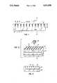
- FIG. 1is an end view of a filter plate constructed in accordance with the present invention
- FIG. 2is an isometric elevational view, showing the inventive filter plate used in association with a display with passive illumination, and
- FIG. 3is an end view showing the inventive filter plate used in association with a cathode ray tube face plate.
- the directional optical filterconsists of a substantially transparent plate 13 having a plurality of grooves 15 cut into one side 16 of the plate 13.
- the grooves 15extend in a parallel fashion across the face of the plate 13, as can be seen in FIG. 2. It is alternatively possible to arrange the grooves 15 in different patterns, such as concentric circles (not shown).
- the grooves 15have a high light absorbency characteristic for light entering the grooves 15 from within the plate 13.
- the absorbency of light passing from within the plate 13 to the grooves 15is 0.9 or greater, where 1.0 is perfect absorbency.
- the grooves 15may be filled with light absorbing material 18 so that light impinging upon the grooves 15 from outside of the plate 13 is also absorbed at the grooves 15.
- the grooves 15are created by etching the plate 13 through a mask.
- the grooves 15are formed by using a special mold for the filter plate 13. The mold (not shown) would have appropriate knife edges along a surface corresponding to side 16 of the plate 13.
- the plate 13is made of a media which is able to transmit the radiant energy to be filtered, in this case light.
- Typical materialsinclude glass, epoxy and methyl methacrylate.
- the mediaitself may have radiant energy filtering properties.
- the mediamay include a polarized light filter, a neutral density partial absorption characteristic or a slective filtration characteristic.
- any light passing through the plate 13will either hit or miss one of the grooves 15 according to the direction that the light is travelling with respect to the plate 13 and the proximity of the light's path to the grooves 15. That light impinging upon the grooves 15 is for the most part absorbed and that light not impinging upon the grooves 15 is for the most part transmitted. Beyond a certain angle ⁇ , substantially all light is absorbed. Taking into account the refraction characteristics of the plate 13 itself, this angle ⁇ translates to an exterior angle of ⁇ . If the grooves 15 are cut normal to the surface on the side 16 of the plate 13 from which they are cut, light impinging upon the grooves from either direction normal to the plate 13, represented by arrows A and B, is transmitted in accordance with:
- Athe absorbency of the plate 13 at other than at the grooves 15;
- Wthe distance or width between adjacent grooves 15.
- ⁇can be obtained by adjusting ⁇ ' for the coefficient of refraction for the plate 13, in accordance with Snell's law.
- the effects of the filter 11are such that the viewer can be looking from either side A or B.
- the viewerwill probably be observering from side A because an anti-reflection coating (not shown) will be used in such a way that the anti-reflection coating will cover the light absorbing material 18 in the grooves 15.
- Anti-glare coatingsare well known, with the anti-glare coatings of the present invention being defined by military specification MIL-C-14806A.
- the optical filter 11is shown placed over a passive display such as a liquid nematic crystal display 21.
- a separate slight dispersing element 23is disposed between the display 21 and the filter 11 in order to provide illumination for the display 21 when needed. This may be necessary where the direction of illuminating light exceeds the angle ⁇ (FIG. 1).
- the illuminating lightwould, of course, come from a preferred direction and have preferred spectral characteristics, thereby reducing induced glare in a manner known to those skilled in the art.
- external light source 25with the filter, provided that the absorbency characteristics of the filter 11 are taken into consideration. In practice, it is unlikely that the optical filter would be used with a purely passive display, but it is anticipated that some displays will use a combination of passive and active display elements, thereby necessitating the use of anti-glare filteration.
- the filter 11is shown as placed against a conventional face plate 31 for a cathode ray tube (CRT). As is the case with the above configurations, it is possible to invert the filter 11 so that the grooves 15 face the displayed image, that is, the image transmitted through a face plate 31.
- CRTcathode ray tube
- the grooves 15can be laid out as concentric circles (not shown), thereby effectively reducing glare from a variety of directions. It is also possible to form the grooves 15 at an angle other than normal to the side 16 from which they extend (configuration not shown). This creates a central viewing direction which is at an angle other than normal to the plate 13.
- the present inventionis also adaptable to shorter wave length energy such as ultraviolet light and to longer wave length energy such as intrared and microwave energy.
Landscapes
- Physics & Mathematics (AREA)
- General Physics & Mathematics (AREA)
- Optics & Photonics (AREA)
- Devices For Indicating Variable Information By Combining Individual Elements (AREA)
- Optical Elements Other Than Lenses (AREA)
Abstract
Description
This invention relates to radiant energy filtration and more specifically to a directional filter which attenuates radiant energy such as light entering the filter from outside of a pre-determined angle of incidence. In particular, the invention is useful for heads down displays in aircraft cockpits, although it may also find utility in a number of other applications using video displays under adverse lighting conditions.
Heads down displays of the type described are used to display a wide variety of aircraft navigational information in the cockpit of the craft. Often, different information is superimposed or is presented in detail which is difficult to read under varying ambient light conditions. When ambient light is low, as in night flying, it is a relatively simple task to reduce the brightness of the aircraft display. On the other hand, there are frequently ambient light conditions which require a display brightness that would be impractical either as a result of the capabilities of the display or the safety or comfort of the viewer. For example, if sunlight is creating a high glare condition, the display would not only have to overcome the glare but be bright enough for the information provided by the display to be discernible over background lighting conditions. Additionally, during the aircraft's maneuvering, lighting conditions can be expected to change rapidly. While an optical sensor can be used to sense ambient light intensity conditions, glare conditions can not always be determined by merely measuring ambient light levels.
The fixed position of the pilot-viewer enables the use of filter techniques which direct light in a single direction. For this reason, directional filters of various types have been placed in front of the CRT displays in order to block light from external sources which would tend to cause glare, while passing that light from the CRT which is traveling in the direction of the viewer. While there is a certain amount of optical amplitude (brightness) loss inherent in the use of any filter, the loss of brightness is compensated for by the decrease in glare conditions.
Prior art light filtration techniques include the use of neutral density filters. Such filters attenuate external source light as well as light from the display; however, external source light necessarily passes the filter twice and, therefore, is blocked by a square of the attenuation of light from the display itself. In the case of monochromatic displays, a notch filter is sometimes used to select the specific colors of light which are generated by or used in connection with the display. Ambient light would be highly filtered because only a small percentage of the ambient light would fall within the range of the notch filter. With the use of color display techniques, the use of a notch filter is less practical since several different wave lengths must be within the admittance bands of the notch filter.
Directional filters are used to transmit light only in a desired direction. If it is anticipated that ambient light which would cause glare would emanate from a direction other than that of the anticipated direction of the viewer from the display, it is possible to filter such ambient light using directional filters. In one type of prior art directional filter, a sheet of material is etched in order to form a large number of holes. The surfaces of the material at the holes have a high absorbency in order to eliminate reflection along the holes and at the surface of the sheet. Frequently, the sheets are stacked in order to enhance the attenuation effect of the filter. This technique is frequently expensive and may have light attenuation characteristics which are excessive.
Another directional filtration technique involves the construction of a filter plate from a plurality of sheets of thin material. The thin sheets are stacked so that each sheet is parallel to an admittance direction of light. The filter plate is taken from the stack of sheets by cutting a slice across the stack. This results in the filter plate being generally orthogonal to the direction of the individual thin sheets from which it is made, with the slice direction varying from the orthogonal direction for central viewing angles which vary from normal to the surface of the filter. This technique is subject to slight optical distortion and such a filter is expensive to produce.
It is, therefore, an object of the present invention to provide a light filter which has high attenuation ratio for unwanted-verses-wanted light. It is desired that such a filter have minimal attenuation of light in a desired viewing direction and have a maximum attenuation of light passing from beyond a given angle. It is further desired that the filter be useable with full color displays, as well as for the viewing of external conditions, as in the case of heads-up displays. It is further desired that the filter maintain a high effectiveness in adverse ambient lighting conditions with a minimum of attenuation of displayed lighting under those adverse conditions. The desired filter would be useful for direct view displays having passive and active illumination characteristics, as well as heads-up displays (HUD'S) and wind screens used for external viewing by humans and electronic sensors.
In accordance with the present invention, a radiant energy filter is formed from a transparent plate having a plurality of etched grooves thereon. The grooves have a high energy absorbency characteristic, particularly for energy radiating toward the grooves from within the plate. Therefore, radiant energy entering the plate from an angle which would cause the radiant energy to impinge upon the grooves is highly attenuated, whereas radiant energy entering the plate and not impinging upon the grooves is attenuated only by the optical characteristics of the plate.
Advantages include a high attenuation-to-attenuation ratio for light entering from beyond a view range, as compared with light entering from within a view range. Further advantages include a high filtration efficiency in a wide variety of applications.
FIG. 1 is an end view of a filter plate constructed in accordance with the present invention;
FIG. 2 is an isometric elevational view, showing the inventive filter plate used in association with a display with passive illumination, and
FIG. 3 is an end view showing the inventive filter plate used in association with a cathode ray tube face plate.
Referring to FIG. 1, and end view of a directional optical filter 11 constructed according to the present invention as shown. The directional optical filter consists of a substantiallytransparent plate 13 having a plurality ofgrooves 15 cut into oneside 16 of theplate 13. In the preferred embodiment, thegrooves 15 extend in a parallel fashion across the face of theplate 13, as can be seen in FIG. 2. It is alternatively possible to arrange thegrooves 15 in different patterns, such as concentric circles (not shown).
Referring again to FIG. 1, thegrooves 15 have a high light absorbency characteristic for light entering thegrooves 15 from within theplate 13. Preferably, the absorbency of light passing from within theplate 13 to thegrooves 15 is 0.9 or greater, where 1.0 is perfect absorbency. Thus, light impinging upon thegrooves 15 is not reflected back into theplate 13. Thegrooves 15 may be filled withlight absorbing material 18 so that light impinging upon thegrooves 15 from outside of theplate 13 is also absorbed at thegrooves 15.
In the preferred embodiment, thegrooves 15 are created by etching theplate 13 through a mask. Alternatively, thegrooves 15 are formed by using a special mold for thefilter plate 13. The mold (not shown) would have appropriate knife edges along a surface corresponding toside 16 of theplate 13.
Theplate 13 is made of a media which is able to transmit the radiant energy to be filtered, in this case light. Typical materials include glass, epoxy and methyl methacrylate. In order to enhance filtration, the media itself may have radiant energy filtering properties. For example, the media may include a polarized light filter, a neutral density partial absorption characteristic or a slective filtration characteristic.
Referring again to FIG. 1, any light passing through theplate 13 will either hit or miss one of thegrooves 15 according to the direction that the light is travelling with respect to theplate 13 and the proximity of the light's path to thegrooves 15. That light impinging upon thegrooves 15 is for the most part absorbed and that light not impinging upon thegrooves 15 is for the most part transmitted. Beyond a certain angle φ, substantially all light is absorbed. Taking into account the refraction characteristics of theplate 13 itself, this angle φ translates to an exterior angle of φ. If thegrooves 15 are cut normal to the surface on theside 16 of theplate 13 from which they are cut, light impinging upon the grooves from either direction normal to theplate 13, represented by arrows A and B, is transmitted in accordance with:
A[G/(G+W)],
where
A=the absorbency of theplate 13 at other than at thegrooves 15;
G=the maximum width of the grooves; and
W=the distance or width betweenadjacent grooves 15.
This absorbency rate is maintained more or less constant for angles from the normal direction which do not exceed the angular cut from normal of thegrooves 15. The absorbency of the filter 11 is reduced in a linear fashion between that angular direction and φ (or φ', according to one's point of reference). φ itself is determined by: ##EQU1## so that
φ'=arctan D/(W-G),
where
D=depth of thegrooves 15.
φ can be obtained by adjusting φ' for the coefficient of refraction for theplate 13, in accordance with Snell's law.
As can be seen, the effects of the filter 11 are such that the viewer can be looking from either side A or B. In the preferred embodiment, the viewer will probably be observering from side A because an anti-reflection coating (not shown) will be used in such a way that the anti-reflection coating will cover thelight absorbing material 18 in thegrooves 15. Anti-glare coatings are well known, with the anti-glare coatings of the present invention being defined by military specification MIL-C-14806A.
Referring to FIG. 2, the optical filter 11 is shown placed over a passive display such as a liquidnematic crystal display 21. A separateslight dispersing element 23 is disposed between thedisplay 21 and the filter 11 in order to provide illumination for thedisplay 21 when needed. This may be necessary where the direction of illuminating light exceeds the angle φ (FIG. 1). The illuminating light would, of course, come from a preferred direction and have preferred spectral characteristics, thereby reducing induced glare in a manner known to those skilled in the art. It is also possible to use externallight source 25 with the filter, provided that the absorbency characteristics of the filter 11 are taken into consideration. In practice, it is unlikely that the optical filter would be used with a purely passive display, but it is anticipated that some displays will use a combination of passive and active display elements, thereby necessitating the use of anti-glare filteration.
Referring to FIG. 3, the filter 11 is shown as placed against aconventional face plate 31 for a cathode ray tube (CRT). As is the case with the above configurations, it is possible to invert the filter 11 so that thegrooves 15 face the displayed image, that is, the image transmitted through aface plate 31.
While parallel grooves, such as shown in FIG. 2, have been described, it is also possible to use other arrangements for the pattern of thegrooves 15. For example, thegrooves 15 can be laid out as concentric circles (not shown), thereby effectively reducing glare from a variety of directions. It is also possible to form thegrooves 15 at an angle other than normal to theside 16 from which they extend (configuration not shown). This creates a central viewing direction which is at an angle other than normal to theplate 13.
In practical applications, it is anticipated that plural filters, having the grooves extending in an orthogonal direction, will be used. Referring to FIG. 3, two filters would be stacked in the same manner that filter 11 andplate 31 are shown stacked. Alternatively, it is possible to cut a second set of grooves (not shown) on thesame plate 13, orthogonal togrooves 15, on the same or opposite side of theplate 13 asgrooves 15.
While the filter 11 has been described in terms of visible light, the present invention is also adaptable to shorter wave length energy such as ultraviolet light and to longer wave length energy such as intrared and microwave energy.
Inasmuch as the present invention can be adapted to a wide variety of specific configurations, it is desired that the present invention can be read as limited only by the claims.
Claims (17)
1. Filter for selectively admitting radiant energy to pass therethrough including at least one radiant energy transmitting media having first and second sides, and a surface of the media on the first side, wherein an image on one side of the media can be viewed from the other side, characterized by:
said surface being interrupted by a plurality of light-absorbing grooves, the plurality of grooves extending from said surface, extending less than completely through the media and arranged in a pattern, the grooves having a characteristic of absorbing said radiant energy impinging thereon from within the media, such that radiant energy passing said surface from a pre-determined angle from normal to said surface is substantially absorbed and radiant energy passing said surface from less than said pre-determined angle and not impinging upon the grooves is transmitted in accordance with radiant energy transmitting characteristics of said media for that energy.
2. Apparatus as described in claim 1 further characterized by the radiant energy being light.
3. Apparatus as described in claim 1 further characterized by said media being a solid material.
4. Apparatus as described in claim 1 further characterized by the media being a flat plate.
5. Apparatus as described in claim 1 further characterized by the media having a characteristic of selectively absorbing light which does not impinge upon the grooves.
6. Apparatus as described in claim 1 further characterized by th media having a characteristic of partially absorbing that light which does not impinge upon the grooves.
7. Apparatus as defined in claim 1 further characterized by an anti-glare coating, which is applied to one side of the media.
8. Apparatus as defined in claim 1 further characterized by the grooves being arranged in a pattern such that the grooves extend along said surface in a parallel direction with respect to each other.
9. Apparatus as defined in claim 8 further characterized by:
a second radiant energy transmitting media, having a second set of grooves cut therein in a parallel direction with respect to each other;
the second media being disposed adjacent to one of the sides of said one media so that the grooves in the second media are substantially orthogonal to the grooves in said one media.
10. Apparatus as described in claim 8 further characterized by a second set of grooves extending in a parallel direction with respect to each other, the second set of grooves being disposed in an orthogonal direction to the first set of grooves.
11. Apparatus as claimed in claim 1 further characterized by the grooves being arranged in a pattern such that adjacent grooves form concentric circles on said surface.
12. Apparatus as described in claim 1 further characterized by the grooves extending from said surface at an angle from normal to the surface.
13. Apparatus as described in claim 1 further characterized by the media being glass.
14. Apparatus as described in claim 1 further characterized by the media being plastic.
15. Apparatus as described in claim 14 further characterized by the media being methyl methacrylate.
16. Apparatus as described in claim 14 further characterized by the media being epoxy.
17. A video display including a cathode ray tube and a filter for selectively admitting radiant energy to pass therethrough, the filter including at least one radiant energy transmitting media having first and second sides and a surface of the media on the first side wherein an image on one side of the media can be viewed from the other side, characterized by:
said surface being interrupted by a plurality of light-absorbing grooves which are cut into said surface so as to extend less than completely through the media, the plurality of grooves extending from said surface and arranged in a pattern, the grooves having a characteristic of absorbing said radiant energy impinging thereon from within the media, such that radiant energy passing said surface from pre-determined angle from normal to said surface is substantially absorbed and radiant energy passing said surface form less than said pre-determined angle and not impinging upon the grooves is transmitted in accordance with radiant energy transmitting characteristics of said media for that energy.
Priority Applications (3)
| Application Number | Priority Date | Filing Date | Title |
|---|---|---|---|
| US06/476,297US4621898A (en) | 1983-03-17 | 1983-03-17 | Directional optical filter |
| EP84400518AEP0122830A3 (en) | 1983-03-17 | 1984-03-14 | Directional optical filter |
| JP59049381AJPS59177501A (en) | 1983-03-17 | 1984-03-16 | Filter |
Applications Claiming Priority (1)
| Application Number | Priority Date | Filing Date | Title |
|---|---|---|---|
| US06/476,297US4621898A (en) | 1983-03-17 | 1983-03-17 | Directional optical filter |
Publications (1)
| Publication Number | Publication Date |
|---|---|
| US4621898Atrue US4621898A (en) | 1986-11-11 |
Family
ID=23891286
Family Applications (1)
| Application Number | Title | Priority Date | Filing Date |
|---|---|---|---|
| US06/476,297Expired - Fee RelatedUS4621898A (en) | 1983-03-17 | 1983-03-17 | Directional optical filter |
Country Status (3)
| Country | Link |
|---|---|
| US (1) | US4621898A (en) |
| EP (1) | EP0122830A3 (en) |
| JP (1) | JPS59177501A (en) |
Cited By (97)
| Publication number | Priority date | Publication date | Assignee | Title |
|---|---|---|---|---|
| US4973139A (en)* | 1989-04-07 | 1990-11-27 | Hughes Aircraft Company | Automotive head-up display |
| US4997263A (en)* | 1989-06-12 | 1991-03-05 | Allied-Signal Inc. | Ambient light illuminated liquid crystal display system |
| US5204160A (en)* | 1988-08-08 | 1993-04-20 | Minnesota Mining And Manufacturing Company | Light-collimating film |
| US5243464A (en)* | 1992-07-20 | 1993-09-07 | Martin Marietta Energy Systems, Inc. | Damage tolerant light absorbing material |
| US5382985A (en)* | 1991-06-14 | 1995-01-17 | The United States Of America As Represented By The Secretary Of The Air Force | Thermorefractive optical switch |
| US5745293A (en)* | 1995-08-28 | 1998-04-28 | Aerospatiale Societe Nationale Industrielle | Light trap |
| US5877829A (en)* | 1995-11-14 | 1999-03-02 | Sharp Kabushiki Kaisha | Liquid crystal display apparatus having adjustable viewing angle characteristics |
| US6239911B1 (en)* | 1996-04-10 | 2001-05-29 | Kimoto Co., Ltd. | View angle control sheet and method for producing the same |
| WO2001084522A3 (en)* | 2000-04-28 | 2002-03-07 | L 3 Comm Corp | Head-up display simulator system |
| WO2002041048A1 (en)* | 2000-11-15 | 2002-05-23 | 3M Innovative Properties Company | Light control device |
| US6473220B1 (en) | 1998-01-22 | 2002-10-29 | Trivium Technologies, Inc. | Film having transmissive and reflective properties |
| US20030210535A1 (en)* | 2002-05-09 | 2003-11-13 | Gaides Gary E. | Display device |
| US20030231151A1 (en)* | 2002-06-17 | 2003-12-18 | Barlow James E. | Apparatus and method for light enhancing |
| US6688681B2 (en)* | 2001-12-29 | 2004-02-10 | Arvinmeritor Gmbh | Sun blind assembly |
| US20050007000A1 (en)* | 2000-11-02 | 2005-01-13 | 3M Innovative Properties Company | Brightness and contrast enhancement of direct view emissive displays |
| US20050018103A1 (en)* | 2003-05-20 | 2005-01-27 | Lubart Neil D. | Devices for use in non-emissive displays |
| US20060104084A1 (en)* | 2004-11-18 | 2006-05-18 | Hiroyuki Amemiya | View angle controlling sheet and liquid crystal display apparatus using the same |
| US20060103779A1 (en)* | 2004-11-18 | 2006-05-18 | Hiroyuki Amemiya | View angle controlling sheet and liquid crystal display apparatus using the same |
| US20060245060A1 (en)* | 2004-05-25 | 2006-11-02 | Masahiro Goto | Viewing-angle control sheet |
| US20070160811A1 (en)* | 2006-01-12 | 2007-07-12 | 3M Innovative Properties Company | Light-collimating film |
| US20080089094A1 (en)* | 2006-10-12 | 2008-04-17 | Masahiko Yatsu | Image display device and light diffusion component for use therein |
| US20080130121A1 (en)* | 2006-12-05 | 2008-06-05 | Kangyoon Kim | Film for display device, filter including film and display device including filter |
| US20080193721A1 (en)* | 2005-08-31 | 2008-08-14 | Michael Ukelis | Methods for Structuring Substrate Surfaces |
| US7573642B2 (en) | 2002-03-26 | 2009-08-11 | Brilliant Film Llc | System for collimating backlight |
| US20090213593A1 (en)* | 2008-02-26 | 2009-08-27 | Reflexite Corporation | Optical device and system for black level enhancement and methods of use thereof |
| US20090237950A1 (en)* | 2008-03-24 | 2009-09-24 | I/O Controls Corporation | Low glare lighting for a transit vehicle |
| US7595934B2 (en) | 2002-03-26 | 2009-09-29 | Brilliant Film Llc | Integrated sub-assembly having a light collimating or transflecting device |
| US20090244711A1 (en)* | 2008-03-21 | 2009-10-01 | Fujinon Corporation | Imaging filter |
| US20090284727A1 (en)* | 2008-02-14 | 2009-11-19 | Nikon Corporation | Illumination optical system, exposure apparatus, device manufacturing method, compensation filter, and exposure optical system |
| US20100007818A1 (en)* | 2006-06-20 | 2010-01-14 | Nec Corporation | Illumination apparatus, illuminating method and display apparatus |
| US20100033827A1 (en)* | 2008-08-07 | 2010-02-11 | Reflexite Corporation | Optical device and system for privacy or contrast enhancement and methods of use thereof |
| US20100051176A1 (en)* | 2008-08-28 | 2010-03-04 | Reflexite Corporation | Method for making an optical device and system for privacy or contrast enhancement |
| US20100177255A1 (en)* | 2007-06-20 | 2010-07-15 | Zeev Tamir | Methods systems and devices for utilizing directions of light rays |
| US20100214506A1 (en)* | 2007-10-16 | 2010-08-26 | Gaides Gary E | Higher transmission light control film |
| WO2010104827A1 (en) | 2009-03-10 | 2010-09-16 | 3M Innovative Properties Company | User interface with a composite image that floats |
| US7800825B2 (en) | 2006-12-04 | 2010-09-21 | 3M Innovative Properties Company | User interface including composite images that float |
| US20100264163A1 (en)* | 2008-11-13 | 2010-10-21 | Tevs Nikolai R | Product Dispensing Apparatus And Method |
| US20100271721A1 (en)* | 2007-12-21 | 2010-10-28 | Gaides Gary E | Light control film |
| US8072626B2 (en) | 2004-12-02 | 2011-12-06 | 3M Innovative Properties Company | System for reading and authenticating a composite image in a sheeting |
| US8226253B2 (en) | 2008-02-27 | 2012-07-24 | Lubart Neil D | Concentrators for solar power generating systems |
| USD678294S1 (en) | 2012-04-13 | 2013-03-19 | 3M Innovative Properties Company | Case for a tablet electronic device |
| WO2012162458A3 (en)* | 2011-05-25 | 2013-04-04 | 3M Innovative Properties Company | Light control film |
| US8459807B2 (en) | 2007-07-11 | 2013-06-11 | 3M Innovative Properties Company | Sheeting with composite image that floats |
| US8514493B2 (en) | 2008-10-23 | 2013-08-20 | 3M Innovative Properties Company | Methods of forming sheeting with composite images that float and sheeting with composite images that float |
| USD689054S1 (en) | 2012-01-09 | 2013-09-03 | 3M Innovative Properties Company | Foldable case for a tablet electronic device |
| USD689055S1 (en) | 2012-01-09 | 2013-09-03 | 3M Innovative Properties Company | Multi-panel case for a tablet electronic device |
| US8537470B2 (en) | 2008-10-23 | 2013-09-17 | 3M Innovative Properties Company | Methods of forming sheeting with composite images that float and sheeting with composite images that float |
| US8586285B2 (en) | 2007-11-27 | 2013-11-19 | 3M Innovative Properties Company | Methods for forming sheeting with a composite image that floats and a master tooling |
| US8758882B2 (en) | 2010-03-25 | 2014-06-24 | 3M Innovative Properties Company | Composite layer |
| WO2014190404A1 (en)* | 2013-05-31 | 2014-12-04 | Massaru Amemiya Roberto | Rays tridimensional capture camcorder and television to produce a real image formed in the front and in the back surface of said television; parallel rays filter devices; leveled liquid crystals or optical cells movement or parallel rays filter with a set of moving lenses including multi focal flexible lenses; methods for obtaining theses said devices |
| US9063284B2 (en) | 2009-06-18 | 2015-06-23 | 3M Innovative Properties Company | Light control film |
| WO2016003669A1 (en)* | 2014-06-30 | 2016-01-07 | 3M Innovative Properties Company | 360 degree privacy film |
| US9327429B2 (en) | 2010-03-25 | 2016-05-03 | 3M Innovative Properties Company | Extrusion die element, extrusion die and method for making multiple stripe extrudate |
| US20160124126A1 (en)* | 2014-10-29 | 2016-05-05 | Sergiy Vasylyev | Angular selective light control sheeting and method of making the same |
| US9724865B2 (en) | 2011-10-05 | 2017-08-08 | 3M Innovative Properties Company | Three-dimensional polymeric strand netting, dies, and methods of making the same |
| US10185058B2 (en) | 2013-07-01 | 2019-01-22 | 3M Innovative Properties Company | Protection film suitable for illuminated display devices |
| US20190187549A1 (en)* | 2017-12-14 | 2019-06-20 | Nano Precision Taiwan Limited | Projection screen and light absorbing film |
| US10449700B2 (en) | 2012-03-26 | 2019-10-22 | 3M Innovative Properties Company | Methods of making films comprising an array of openings |
| WO2021026018A1 (en)* | 2019-08-02 | 2021-02-11 | Reald Spark, Llc | Optical stack for privacy display |
| US10948648B2 (en) | 2017-09-29 | 2021-03-16 | Reald Spark, Llc | Backlights having stacked waveguide and optical components with different coefficients of friction |
| US10955715B2 (en) | 2018-06-29 | 2021-03-23 | Reald Spark, Llc | Optical stack for privacy display |
| US10976578B2 (en) | 2018-01-25 | 2021-04-13 | Reald Spark, Llc | Reflective optical stack for privacy display |
| US11016318B2 (en) | 2017-05-08 | 2021-05-25 | Reald Spark, Llc | Optical stack for switchable directional display |
| US11029566B2 (en) | 2019-02-12 | 2021-06-08 | Reald Spark, Llc | Diffuser for privacy display |
| US11030981B2 (en) | 2015-10-26 | 2021-06-08 | Reald Spark, Llc | Intelligent privacy system, apparatus, and method thereof |
| US11041338B2 (en)* | 2018-08-21 | 2021-06-22 | California Institute Of Technology | Windows implementing effectively transparent conductors and related methods of manufacturing |
| US11070791B2 (en) | 2017-11-06 | 2021-07-20 | Reald Spark, Llc | Privacy display apparatus |
| US11073735B2 (en) | 2018-07-18 | 2021-07-27 | Reald Spark, Llc | Optical stack for switchable directional display |
| US11079619B2 (en) | 2016-05-19 | 2021-08-03 | Reald Spark, Llc | Wide angle imaging directional backlights |
| US11079646B2 (en) | 2019-11-13 | 2021-08-03 | Reald Spark, Llc | Display device off-axis luminance reduction uniformity |
| US11092852B2 (en) | 2018-11-07 | 2021-08-17 | Reald Spark, Llc | Directional display apparatus |
| US11092851B2 (en) | 2017-09-15 | 2021-08-17 | Reald Spark, Llc | Optical stack for switchable directional display |
| US11106103B2 (en) | 2018-10-03 | 2021-08-31 | Reald Spark, Llc | Privacy display apparatus controlled in response to environment of apparatus |
| US20210271095A1 (en)* | 2018-07-12 | 2021-09-02 | Lg Innotek Co., Ltd. | Optical path control member and display device comprising same |
| US11114063B2 (en) | 2019-10-02 | 2021-09-07 | Reald Spark, Llc | Privacy display apparatus |
| WO2021222598A1 (en)* | 2020-04-30 | 2021-11-04 | Reald Spark, Llc | Directional display apparatus |
| US11187945B2 (en) | 2018-01-25 | 2021-11-30 | Reald Spark, Llc | Touch screen for privacy display |
| US11191146B2 (en) | 2019-12-18 | 2021-11-30 | Reald Spark, Llc | Control of ambient light for a privacy display |
| US11227964B2 (en) | 2017-08-25 | 2022-01-18 | California Institute Of Technology | Luminescent solar concentrators and related methods of manufacturing |
| US11237417B2 (en) | 2020-04-30 | 2022-02-01 | Reald Spark, Llc | Directional display apparatus |
| US11287677B2 (en) | 2019-01-07 | 2022-03-29 | Reald Spark, Llc | Optical stack for privacy display |
| US11320575B2 (en) | 2018-03-22 | 2022-05-03 | Reald Spark, Llc | Optical waveguide for directional backlight |
| US11327358B2 (en) | 2017-05-08 | 2022-05-10 | Reald Spark, Llc | Optical stack for directional display |
| US11340482B2 (en) | 2020-07-29 | 2022-05-24 | Reald Spark, Llc | Pupillated illumination apparatus |
| US11353752B2 (en) | 2020-04-30 | 2022-06-07 | Reald Spark, Llc | Directional display apparatus |
| US11362229B2 (en) | 2018-04-04 | 2022-06-14 | California Institute Of Technology | Epitaxy-free nanowire cell process for the manufacture of photovoltaics |
| US11573437B2 (en) | 2019-07-02 | 2023-02-07 | Reald Spark, Llc | Directional display apparatus |
| US11624944B2 (en) | 2020-07-29 | 2023-04-11 | Reald Spark, Llc | Backlight for switchable directional display |
| US11796828B2 (en) | 2019-12-10 | 2023-10-24 | Reald Spark, Llc | Control of reflections of a display device |
| US11892717B2 (en) | 2021-09-30 | 2024-02-06 | Reald Spark, Llc | Marks for privacy display |
| US11892718B2 (en) | 2022-04-07 | 2024-02-06 | Reald Spark, Llc | Directional display apparatus |
| US11939688B2 (en) | 2019-03-29 | 2024-03-26 | California Institute Of Technology | Apparatus and systems for incorporating effective transparent catalyst for photoelectrochemical application |
| US11977286B2 (en) | 2022-02-09 | 2024-05-07 | Reald Spark, Llc | Observer-tracked privacy display |
| US12253748B2 (en) | 2023-04-25 | 2025-03-18 | Reald Spark, Llc | Switchable privacy display |
| US12366701B2 (en) | 2017-05-08 | 2025-07-22 | Reald Spark, Llc | Optical stack for imaging directional backlights |
| US12393066B2 (en) | 2023-08-03 | 2025-08-19 | Reald Spark, Llc | Privacy displays |
| US12402418B2 (en) | 2020-06-12 | 2025-08-26 | California Institute Of Technology | Systems and methods for non-epitaxial high Schottky-barrier heterojunction solar cells |
Families Citing this family (3)
| Publication number | Priority date | Publication date | Assignee | Title |
|---|---|---|---|---|
| JPH0430561Y2 (en)* | 1985-06-21 | 1992-07-23 | ||
| EP0354672A3 (en)* | 1988-08-08 | 1990-10-10 | Minnesota Mining And Manufacturing Company | Light-collimating film |
| CH690657A5 (en)* | 1993-12-01 | 2000-11-30 | Olga Raimondi Staeuble | A directional filter for the light fittings. |
Citations (3)
| Publication number | Priority date | Publication date | Assignee | Title |
|---|---|---|---|---|
| US2053173A (en)* | 1930-05-14 | 1936-09-01 | Astima Eugene | Shadow producing screen for luminous projections and other applications and process for its manufacture |
| US2909770A (en)* | 1953-11-25 | 1959-10-20 | Gen Electric | Transmission screen |
| US3784282A (en)* | 1971-03-05 | 1974-01-08 | Hitachi Ltd | Correcting lens used to form fluorescent screens of colour television receiving tubes |
Family Cites Families (4)
| Publication number | Priority date | Publication date | Assignee | Title |
|---|---|---|---|---|
| US3215776A (en)* | 1963-04-29 | 1965-11-02 | Douglas Aircraft Co Inc | Television set with ambient light trapping filter |
| US3215777A (en)* | 1963-10-15 | 1965-11-02 | Douglas Aircraft Co Inc | Ambient light trapping filter for cathode ray tubes |
| US4076978A (en)* | 1975-07-07 | 1978-02-28 | Baird-Atomic, Inc. | Fiber optic bundle beam expander with image intensifier |
| FR2462723A1 (en)* | 1979-07-27 | 1981-02-13 | Thomson Csf | DIRECTIVE FILTER FOR DISPLAY SCREEN, METHOD FOR MANUFACTURING SAME, AND VISUALIZATION SYSTEM, IN PARTICULAR CATHODIC TUBE, PROVIDED WITH SUCH A FILTER |
- 1983
- 1983-03-17USUS06/476,297patent/US4621898A/ennot_activeExpired - Fee Related
- 1984
- 1984-03-14EPEP84400518Apatent/EP0122830A3/ennot_activeCeased
- 1984-03-16JPJP59049381Apatent/JPS59177501A/enactivePending
Patent Citations (3)
| Publication number | Priority date | Publication date | Assignee | Title |
|---|---|---|---|---|
| US2053173A (en)* | 1930-05-14 | 1936-09-01 | Astima Eugene | Shadow producing screen for luminous projections and other applications and process for its manufacture |
| US2909770A (en)* | 1953-11-25 | 1959-10-20 | Gen Electric | Transmission screen |
| US3784282A (en)* | 1971-03-05 | 1974-01-08 | Hitachi Ltd | Correcting lens used to form fluorescent screens of colour television receiving tubes |
Cited By (168)
| Publication number | Priority date | Publication date | Assignee | Title |
|---|---|---|---|---|
| US5204160A (en)* | 1988-08-08 | 1993-04-20 | Minnesota Mining And Manufacturing Company | Light-collimating film |
| US4973139A (en)* | 1989-04-07 | 1990-11-27 | Hughes Aircraft Company | Automotive head-up display |
| US4997263A (en)* | 1989-06-12 | 1991-03-05 | Allied-Signal Inc. | Ambient light illuminated liquid crystal display system |
| US5382985A (en)* | 1991-06-14 | 1995-01-17 | The United States Of America As Represented By The Secretary Of The Air Force | Thermorefractive optical switch |
| US5243464A (en)* | 1992-07-20 | 1993-09-07 | Martin Marietta Energy Systems, Inc. | Damage tolerant light absorbing material |
| US5745293A (en)* | 1995-08-28 | 1998-04-28 | Aerospatiale Societe Nationale Industrielle | Light trap |
| US5877829A (en)* | 1995-11-14 | 1999-03-02 | Sharp Kabushiki Kaisha | Liquid crystal display apparatus having adjustable viewing angle characteristics |
| US6239911B1 (en)* | 1996-04-10 | 2001-05-29 | Kimoto Co., Ltd. | View angle control sheet and method for producing the same |
| US6473220B1 (en) | 1998-01-22 | 2002-10-29 | Trivium Technologies, Inc. | Film having transmissive and reflective properties |
| US20060023289A1 (en)* | 1998-01-22 | 2006-02-02 | Clikeman Richard W | Device having reflective and transmissive properties |
| US7236286B2 (en) | 1998-01-22 | 2007-06-26 | Brilliant Film Llc | Device having reflective and transmissive properties |
| WO2001084522A3 (en)* | 2000-04-28 | 2002-03-07 | L 3 Comm Corp | Head-up display simulator system |
| US6612840B1 (en)* | 2000-04-28 | 2003-09-02 | L-3 Communications Corporation | Head-up display simulator system |
| US20050007000A1 (en)* | 2000-11-02 | 2005-01-13 | 3M Innovative Properties Company | Brightness and contrast enhancement of direct view emissive displays |
| US6398370B1 (en) | 2000-11-15 | 2002-06-04 | 3M Innovative Properties Company | Light control device |
| WO2002041048A1 (en)* | 2000-11-15 | 2002-05-23 | 3M Innovative Properties Company | Light control device |
| US6688681B2 (en)* | 2001-12-29 | 2004-02-10 | Arvinmeritor Gmbh | Sun blind assembly |
| US7595934B2 (en) | 2002-03-26 | 2009-09-29 | Brilliant Film Llc | Integrated sub-assembly having a light collimating or transflecting device |
| US7573642B2 (en) | 2002-03-26 | 2009-08-11 | Brilliant Film Llc | System for collimating backlight |
| US6905219B2 (en) | 2002-05-09 | 2005-06-14 | 3M Innovative Properties Company | Display device |
| US20030210535A1 (en)* | 2002-05-09 | 2003-11-13 | Gaides Gary E. | Display device |
| US20030231151A1 (en)* | 2002-06-17 | 2003-12-18 | Barlow James E. | Apparatus and method for light enhancing |
| US7573550B2 (en) | 2003-05-20 | 2009-08-11 | Brilliant Film, Llc | Devices for use in non-emissive displays |
| US20050018103A1 (en)* | 2003-05-20 | 2005-01-27 | Lubart Neil D. | Devices for use in non-emissive displays |
| US20060245060A1 (en)* | 2004-05-25 | 2006-11-02 | Masahiro Goto | Viewing-angle control sheet |
| US7686463B2 (en)* | 2004-05-25 | 2010-03-30 | Dai Nippon Printing Co., Ltd. | Viewing-angle control sheet |
| US20060103779A1 (en)* | 2004-11-18 | 2006-05-18 | Hiroyuki Amemiya | View angle controlling sheet and liquid crystal display apparatus using the same |
| US20060104084A1 (en)* | 2004-11-18 | 2006-05-18 | Hiroyuki Amemiya | View angle controlling sheet and liquid crystal display apparatus using the same |
| US8072626B2 (en) | 2004-12-02 | 2011-12-06 | 3M Innovative Properties Company | System for reading and authenticating a composite image in a sheeting |
| US20080193721A1 (en)* | 2005-08-31 | 2008-08-14 | Michael Ukelis | Methods for Structuring Substrate Surfaces |
| DE112007000148T5 (en) | 2006-01-12 | 2008-11-20 | 3M Innovative Properties Co., St. Paul | Light collimating film |
| US8133572B2 (en) | 2006-01-12 | 2012-03-13 | 3M Innovative Properties Company | Light collimating film |
| US8012567B2 (en) | 2006-01-12 | 2011-09-06 | 3M Innovative Properties Company | Light-collimating film |
| US20070160811A1 (en)* | 2006-01-12 | 2007-07-12 | 3M Innovative Properties Company | Light-collimating film |
| CN101473168B (en)* | 2006-06-20 | 2012-04-18 | 日本电气株式会社 | Illuminating apparatus, illuminating method and display apparatus |
| US20100007818A1 (en)* | 2006-06-20 | 2010-01-14 | Nec Corporation | Illumination apparatus, illuminating method and display apparatus |
| US20080089094A1 (en)* | 2006-10-12 | 2008-04-17 | Masahiko Yatsu | Image display device and light diffusion component for use therein |
| US7712911B2 (en)* | 2006-10-12 | 2010-05-11 | Hitachi, Ltd. | Image display device and light diffusion component for use therein |
| US7800825B2 (en) | 2006-12-04 | 2010-09-21 | 3M Innovative Properties Company | User interface including composite images that float |
| US20080130121A1 (en)* | 2006-12-05 | 2008-06-05 | Kangyoon Kim | Film for display device, filter including film and display device including filter |
| US20100177255A1 (en)* | 2007-06-20 | 2010-07-15 | Zeev Tamir | Methods systems and devices for utilizing directions of light rays |
| US8416355B2 (en) | 2007-06-20 | 2013-04-09 | Tc View Ltd. | Directional filter device for controlling direction of maximal blocking of incident light |
| US8459807B2 (en) | 2007-07-11 | 2013-06-11 | 3M Innovative Properties Company | Sheeting with composite image that floats |
| US9335449B2 (en) | 2007-10-16 | 2016-05-10 | 3M Innovative Properties Company | Higher transmission light control film |
| US9804311B2 (en) | 2007-10-16 | 2017-10-31 | 3M Innovative Properties Company | Higher transmission light control film comprising a transmissive region and an absorptive region each having a different index of refraction |
| US20100214506A1 (en)* | 2007-10-16 | 2010-08-26 | Gaides Gary E | Higher transmission light control film |
| EP2208096B1 (en) | 2007-10-16 | 2019-11-27 | 3M Innovative Properties Company | Higher transmission light control film |
| US8586285B2 (en) | 2007-11-27 | 2013-11-19 | 3M Innovative Properties Company | Methods for forming sheeting with a composite image that floats and a master tooling |
| US20100271721A1 (en)* | 2007-12-21 | 2010-10-28 | Gaides Gary E | Light control film |
| US8213082B2 (en)* | 2007-12-21 | 2012-07-03 | 3M Innovative Properties Company | Light control film |
| US20090284727A1 (en)* | 2008-02-14 | 2009-11-19 | Nikon Corporation | Illumination optical system, exposure apparatus, device manufacturing method, compensation filter, and exposure optical system |
| US8908151B2 (en) | 2008-02-14 | 2014-12-09 | Nikon Corporation | Illumination optical system, exposure apparatus, device manufacturing method, compensation filter, and exposure optical system |
| US20090213593A1 (en)* | 2008-02-26 | 2009-08-27 | Reflexite Corporation | Optical device and system for black level enhancement and methods of use thereof |
| US8226253B2 (en) | 2008-02-27 | 2012-07-24 | Lubart Neil D | Concentrators for solar power generating systems |
| US20090244711A1 (en)* | 2008-03-21 | 2009-10-01 | Fujinon Corporation | Imaging filter |
| US8210724B2 (en) | 2008-03-24 | 2012-07-03 | I/O Controls Corporation | Low glare lighting for a transit vehicle |
| US20090237950A1 (en)* | 2008-03-24 | 2009-09-24 | I/O Controls Corporation | Low glare lighting for a transit vehicle |
| US8740425B2 (en) | 2008-03-24 | 2014-06-03 | I/O Controls Corporation | Low glare lighting for a transit vehicle |
| US20100033827A1 (en)* | 2008-08-07 | 2010-02-11 | Reflexite Corporation | Optical device and system for privacy or contrast enhancement and methods of use thereof |
| US8205995B2 (en) | 2008-08-07 | 2012-06-26 | Reflexite Corporation | Optical device and system for privacy or contrast enhancement and methods of use thereof |
| US20100051176A1 (en)* | 2008-08-28 | 2010-03-04 | Reflexite Corporation | Method for making an optical device and system for privacy or contrast enhancement |
| US8057715B2 (en) | 2008-08-28 | 2011-11-15 | Reflexite Corporation | Method for making an optical device and system for privacy or contrast enhancement |
| US8537470B2 (en) | 2008-10-23 | 2013-09-17 | 3M Innovative Properties Company | Methods of forming sheeting with composite images that float and sheeting with composite images that float |
| US8514493B2 (en) | 2008-10-23 | 2013-08-20 | 3M Innovative Properties Company | Methods of forming sheeting with composite images that float and sheeting with composite images that float |
| US20100264163A1 (en)* | 2008-11-13 | 2010-10-21 | Tevs Nikolai R | Product Dispensing Apparatus And Method |
| WO2010104827A1 (en) | 2009-03-10 | 2010-09-16 | 3M Innovative Properties Company | User interface with a composite image that floats |
| DE112010001150T5 (en) | 2009-03-10 | 2012-05-16 | 3M Innovative Properties Company | User interface with a composite image hovering |
| US9268146B2 (en) | 2009-03-10 | 2016-02-23 | 3M Innovative Properties Company | User interface with a composite image that floats |
| US9063284B2 (en) | 2009-06-18 | 2015-06-23 | 3M Innovative Properties Company | Light control film |
| US8758882B2 (en) | 2010-03-25 | 2014-06-24 | 3M Innovative Properties Company | Composite layer |
| US9327429B2 (en) | 2010-03-25 | 2016-05-03 | 3M Innovative Properties Company | Extrusion die element, extrusion die and method for making multiple stripe extrudate |
| EP2409558A1 (en) | 2010-06-30 | 2012-01-25 | Deere & Company | Product dispensing apparatus and control method for such |
| WO2012162458A3 (en)* | 2011-05-25 | 2013-04-04 | 3M Innovative Properties Company | Light control film |
| US9329311B2 (en) | 2011-05-25 | 2016-05-03 | 3M Innovative Properties Company | Light control film |
| US10730220B2 (en) | 2011-10-05 | 2020-08-04 | 3M Innovative Properties Company | Three-dimensional polymeric strand netting, dies, and methods of making the same |
| US9724865B2 (en) | 2011-10-05 | 2017-08-08 | 3M Innovative Properties Company | Three-dimensional polymeric strand netting, dies, and methods of making the same |
| USD689055S1 (en) | 2012-01-09 | 2013-09-03 | 3M Innovative Properties Company | Multi-panel case for a tablet electronic device |
| USD689054S1 (en) | 2012-01-09 | 2013-09-03 | 3M Innovative Properties Company | Foldable case for a tablet electronic device |
| US10449700B2 (en) | 2012-03-26 | 2019-10-22 | 3M Innovative Properties Company | Methods of making films comprising an array of openings |
| USD678294S1 (en) | 2012-04-13 | 2013-03-19 | 3M Innovative Properties Company | Case for a tablet electronic device |
| US10200673B2 (en) | 2013-05-31 | 2019-02-05 | Roberto Massaru Amemiya | Optical system for capturing and reproducing moving real images |
| WO2014190404A1 (en)* | 2013-05-31 | 2014-12-04 | Massaru Amemiya Roberto | Rays tridimensional capture camcorder and television to produce a real image formed in the front and in the back surface of said television; parallel rays filter devices; leveled liquid crystals or optical cells movement or parallel rays filter with a set of moving lenses including multi focal flexible lenses; methods for obtaining theses said devices |
| US10185058B2 (en) | 2013-07-01 | 2019-01-22 | 3M Innovative Properties Company | Protection film suitable for illuminated display devices |
| WO2016003669A1 (en)* | 2014-06-30 | 2016-01-07 | 3M Innovative Properties Company | 360 degree privacy film |
| US10663630B2 (en) | 2014-06-30 | 2020-05-26 | 3M Innovative Properties Company | 360 degree privacy film |
| US20160124126A1 (en)* | 2014-10-29 | 2016-05-05 | Sergiy Vasylyev | Angular selective light control sheeting and method of making the same |
| US11754756B2 (en) | 2014-10-29 | 2023-09-12 | S.V.V. Technology Innovations, Inc. | Angular selective light control sheeting and method of making the same |
| US11030981B2 (en) | 2015-10-26 | 2021-06-08 | Reald Spark, Llc | Intelligent privacy system, apparatus, and method thereof |
| US12392949B2 (en) | 2016-05-19 | 2025-08-19 | Reald Spark, Llc | Wide angle imaging directional backlights |
| US11079619B2 (en) | 2016-05-19 | 2021-08-03 | Reald Spark, Llc | Wide angle imaging directional backlights |
| US11327358B2 (en) | 2017-05-08 | 2022-05-10 | Reald Spark, Llc | Optical stack for directional display |
| US11016318B2 (en) | 2017-05-08 | 2021-05-25 | Reald Spark, Llc | Optical stack for switchable directional display |
| US12366701B2 (en) | 2017-05-08 | 2025-07-22 | Reald Spark, Llc | Optical stack for imaging directional backlights |
| US11227964B2 (en) | 2017-08-25 | 2022-01-18 | California Institute Of Technology | Luminescent solar concentrators and related methods of manufacturing |
| US11099433B2 (en) | 2017-09-15 | 2021-08-24 | Reald Spark, Llc | Switchable directional display apparatus |
| US11474396B2 (en) | 2017-09-15 | 2022-10-18 | Reald Spark, Llc | Optical stack for switchable directional display |
| US11181780B2 (en) | 2017-09-15 | 2021-11-23 | Reald Spark, Llc | Optical stack for switchable directional display |
| US12066717B2 (en) | 2017-09-15 | 2024-08-20 | Reald Spark, Llc | Optical stack for switchable directional display |
| US11092851B2 (en) | 2017-09-15 | 2021-08-17 | Reald Spark, Llc | Optical stack for switchable directional display |
| US11474397B2 (en) | 2017-09-15 | 2022-10-18 | Reald Spark, Llc | Optical stack for switchable directional display |
| US10948648B2 (en) | 2017-09-29 | 2021-03-16 | Reald Spark, Llc | Backlights having stacked waveguide and optical components with different coefficients of friction |
| US11109014B2 (en) | 2017-11-06 | 2021-08-31 | Reald Spark, Llc | Privacy display apparatus |
| US11070791B2 (en) | 2017-11-06 | 2021-07-20 | Reald Spark, Llc | Privacy display apparatus |
| US11431960B2 (en) | 2017-11-06 | 2022-08-30 | Reald Spark, Llc | Privacy display apparatus |
| US11115647B2 (en) | 2017-11-06 | 2021-09-07 | Reald Spark, Llc | Privacy display apparatus |
| US10527922B2 (en)* | 2017-12-14 | 2020-01-07 | Nano Precision Taiwan Limited | Projection screen and light absorbing film |
| US20190187549A1 (en)* | 2017-12-14 | 2019-06-20 | Nano Precision Taiwan Limited | Projection screen and light absorbing film |
| US12038633B2 (en) | 2018-01-25 | 2024-07-16 | Reald Spark, Llc | Reflective optical stack for privacy display |
| US11630336B2 (en) | 2018-01-25 | 2023-04-18 | Reald Spark, Llc | Reflective optical stack for privacy display |
| US12169339B2 (en) | 2018-01-25 | 2024-12-17 | Reald Spark, Llc | Touch screen for privacy display |
| US10976578B2 (en) | 2018-01-25 | 2021-04-13 | Reald Spark, Llc | Reflective optical stack for privacy display |
| US11187945B2 (en) | 2018-01-25 | 2021-11-30 | Reald Spark, Llc | Touch screen for privacy display |
| US11320575B2 (en) | 2018-03-22 | 2022-05-03 | Reald Spark, Llc | Optical waveguide for directional backlight |
| US11808965B2 (en) | 2018-03-22 | 2023-11-07 | Reald Spark, Llc | Optical waveguide for directional backlight |
| US11604311B2 (en) | 2018-03-22 | 2023-03-14 | Reald Spark, Llc | Optical waveguide for directional backlight |
| US11362229B2 (en) | 2018-04-04 | 2022-06-14 | California Institute Of Technology | Epitaxy-free nanowire cell process for the manufacture of photovoltaics |
| US11809052B2 (en) | 2018-06-29 | 2023-11-07 | Reald Spark, Llc | Stabilization for privacy display |
| US11287713B2 (en) | 2018-06-29 | 2022-03-29 | Reald Spark, Llc | Optical stack for privacy display |
| US11079645B2 (en) | 2018-06-29 | 2021-08-03 | Reald Spark, Llc | Stabilization for privacy display |
| US10955715B2 (en) | 2018-06-29 | 2021-03-23 | Reald Spark, Llc | Optical stack for privacy display |
| US11874576B2 (en) | 2018-06-29 | 2024-01-16 | Reald Spark, Llc | Optical stack for privacy display |
| US20210271095A1 (en)* | 2018-07-12 | 2021-09-02 | Lg Innotek Co., Ltd. | Optical path control member and display device comprising same |
| US12174504B2 (en) | 2018-07-18 | 2024-12-24 | Reald Spark, Llc | Optical stack for switchable directional display |
| US11747693B2 (en) | 2018-07-18 | 2023-09-05 | Reald Spark, Llc | Optical stack for switchable directional display |
| US11073735B2 (en) | 2018-07-18 | 2021-07-27 | Reald Spark, Llc | Optical stack for switchable directional display |
| US11041338B2 (en)* | 2018-08-21 | 2021-06-22 | California Institute Of Technology | Windows implementing effectively transparent conductors and related methods of manufacturing |
| US11106103B2 (en) | 2018-10-03 | 2021-08-31 | Reald Spark, Llc | Privacy display apparatus controlled in response to environment of apparatus |
| US12140847B2 (en) | 2018-10-03 | 2024-11-12 | ReaID Spark, LLC | Display apparatus using application software context for privacy control |
| US11092852B2 (en) | 2018-11-07 | 2021-08-17 | Reald Spark, Llc | Directional display apparatus |
| US12038649B2 (en) | 2018-11-07 | 2024-07-16 | Reald Spark, Llc | Directional display apparatus |
| US11287677B2 (en) | 2019-01-07 | 2022-03-29 | Reald Spark, Llc | Optical stack for privacy display |
| US11573439B2 (en) | 2019-01-07 | 2023-02-07 | Reald Spark, Llc | Optical stack for privacy display |
| US11586073B2 (en) | 2019-02-12 | 2023-02-21 | Reald Spark, Llc | Diffuser for privacy display |
| US11029566B2 (en) | 2019-02-12 | 2021-06-08 | Reald Spark, Llc | Diffuser for privacy display |
| US11243437B2 (en) | 2019-02-12 | 2022-02-08 | Reald Spark, Llc | Diffuser for privacy display |
| US11939688B2 (en) | 2019-03-29 | 2024-03-26 | California Institute Of Technology | Apparatus and systems for incorporating effective transparent catalyst for photoelectrochemical application |
| US11573437B2 (en) | 2019-07-02 | 2023-02-07 | Reald Spark, Llc | Directional display apparatus |
| US11874541B2 (en) | 2019-07-02 | 2024-01-16 | Reald Spark, Llc | Directional display apparatus |
| US11454853B2 (en)* | 2019-08-02 | 2022-09-27 | Reald Spark, Llc | Optical stack for privacy display |
| WO2021026018A1 (en)* | 2019-08-02 | 2021-02-11 | Reald Spark, Llc | Optical stack for privacy display |
| US11099447B2 (en)* | 2019-08-02 | 2021-08-24 | Reald Spark, Llc | Optical stack for privacy display |
| US11114063B2 (en) | 2019-10-02 | 2021-09-07 | Reald Spark, Llc | Privacy display apparatus |
| US11462193B2 (en) | 2019-10-02 | 2022-10-04 | Reald Spark, Llc | Privacy display apparatus |
| US12228835B2 (en) | 2019-11-13 | 2025-02-18 | ReaID Spark, LLC | Display device with uniform off-axis luminance reduction |
| US11079646B2 (en) | 2019-11-13 | 2021-08-03 | Reald Spark, Llc | Display device off-axis luminance reduction uniformity |
| US11733578B2 (en) | 2019-11-13 | 2023-08-22 | ReaID Spark, LLC | Display device with uniform off-axis luminance reduction |
| US11099448B2 (en) | 2019-11-13 | 2021-08-24 | Reald Spark, Llc | Off-axis display device |
| US11796828B2 (en) | 2019-12-10 | 2023-10-24 | Reald Spark, Llc | Control of reflections of a display device |
| US12117621B2 (en) | 2019-12-10 | 2024-10-15 | RealD Spark | Control of reflections of a display device |
| US11191146B2 (en) | 2019-12-18 | 2021-11-30 | Reald Spark, Llc | Control of ambient light for a privacy display |
| WO2021222598A1 (en)* | 2020-04-30 | 2021-11-04 | Reald Spark, Llc | Directional display apparatus |
| US11353752B2 (en) | 2020-04-30 | 2022-06-07 | Reald Spark, Llc | Directional display apparatus |
| US11506939B2 (en) | 2020-04-30 | 2022-11-22 | Reald Spark, Llc | Directional display apparatus |
| US11442316B2 (en) | 2020-04-30 | 2022-09-13 | Reald Spark, Llc | Directional display apparatus |
| US11668963B2 (en) | 2020-04-30 | 2023-06-06 | Reald Spark, Llc | Directional display apparatus |
| US11237417B2 (en) | 2020-04-30 | 2022-02-01 | Reald Spark, Llc | Directional display apparatus |
| US12402418B2 (en) | 2020-06-12 | 2025-08-26 | California Institute Of Technology | Systems and methods for non-epitaxial high Schottky-barrier heterojunction solar cells |
| US11740496B2 (en) | 2020-07-29 | 2023-08-29 | Reald Spark, Llc | Pupillated illumination apparatus |
| US12013603B2 (en) | 2020-07-29 | 2024-06-18 | ReaID Spark, LLC | Pupillated illumination apparatus |
| US11340482B2 (en) | 2020-07-29 | 2022-05-24 | Reald Spark, Llc | Pupillated illumination apparatus |
| US11624944B2 (en) | 2020-07-29 | 2023-04-11 | Reald Spark, Llc | Backlight for switchable directional display |
| US11892717B2 (en) | 2021-09-30 | 2024-02-06 | Reald Spark, Llc | Marks for privacy display |
| US11921367B2 (en) | 2021-09-30 | 2024-03-05 | Reald Spark, Llc | Marks for privacy display |
| US12259608B2 (en) | 2022-02-09 | 2025-03-25 | Reald Spark, Llc | Observer-tracked privacy display |
| US11977286B2 (en) | 2022-02-09 | 2024-05-07 | Reald Spark, Llc | Observer-tracked privacy display |
| US11892718B2 (en) | 2022-04-07 | 2024-02-06 | Reald Spark, Llc | Directional display apparatus |
| US12253748B2 (en) | 2023-04-25 | 2025-03-18 | Reald Spark, Llc | Switchable privacy display |
| US12393066B2 (en) | 2023-08-03 | 2025-08-19 | Reald Spark, Llc | Privacy displays |
Also Published As
| Publication number | Publication date |
|---|---|
| EP0122830A2 (en) | 1984-10-24 |
| EP0122830A3 (en) | 1987-06-10 |
| JPS59177501A (en) | 1984-10-08 |
Similar Documents
| Publication | Publication Date | Title |
|---|---|---|
| US4621898A (en) | Directional optical filter | |
| US4068260A (en) | Combination optical low pass filter capable of phase and amplitude modulation | |
| US5280371A (en) | Directional diffuser for a liquid crystal display | |
| CA2178536C (en) | Lcd with reduced canopy reflection | |
| EP0750209B1 (en) | Light guiding sheet | |
| EP0760490B1 (en) | Image display apparatus | |
| US4984872A (en) | Wide viewing angle avionics liquid crystal display | |
| US5543870A (en) | Rear projection screen with high off-axis sunlight rejection | |
| US20040263969A1 (en) | Lenticular antireflection display | |
| JPS61501798A (en) | optical spatial frequency filter | |
| US11347260B2 (en) | Front light module and display device having the same | |
| US4553818A (en) | Directional filter for filtering ambient light | |
| US4473277A (en) | Anti-glare device and method | |
| KR20200062394A (en) | Optical structure and display device | |
| GB2054195A (en) | Colour Selective Directional Mirrors | |
| CN110208902B (en) | Flat lens for imaging | |
| EP1566590A1 (en) | Illumination device and liquid crystal display device | |
| US4995701A (en) | Anti-glare filter with improved viewing area | |
| US4575767A (en) | Low-moire directional optical filter for CRT displays | |
| KR920000919B1 (en) | The display device | |
| US4712869A (en) | Three dimensional stacked reproduction screen | |
| US4515442A (en) | Optical filter device | |
| JP2000047147A (en) | Lens for spectacles | |
| CA1245494A (en) | Light directing faceplate | |
| CN219957903U (en) | Peep-proof structure and peep-proof film |
Legal Events
| Date | Code | Title | Description |
|---|---|---|---|
| AS | Assignment | Owner name:BENDIX CORPORATION, THE BENDIX CENTER, SOUTHFIELD, Free format text:ASSIGNMENT OF ASSIGNORS INTEREST.;ASSIGNOR:COHEN, RICHARD L.;REEL/FRAME:004123/0872 Effective date:19830310 | |
| AS | Assignment | Owner name:ALLIED CORPORATION COLUMBIA ROAD AND PARK AVE., MO Free format text:ASSIGNMENT OF ASSIGNORS INTEREST.;ASSIGNOR:BENDIX CORPORATION THE A DE CORP.;REEL/FRAME:004336/0327 Effective date:19841129 Owner name:ALLIED CORPORATION,NEW JERSEY Free format text:ASSIGNMENT OF ASSIGNORS INTEREST;ASSIGNOR:BENDIX CORPORATION THE A DE CORP.;REEL/FRAME:004336/0327 Effective date:19841129 | |
| FPAY | Fee payment | Year of fee payment:4 | |
| REMI | Maintenance fee reminder mailed | ||
| LAPS | Lapse for failure to pay maintenance fees | ||
| FP | Lapsed due to failure to pay maintenance fee | Effective date:19941116 | |
| STCH | Information on status: patent discontinuation | Free format text:PATENT EXPIRED DUE TO NONPAYMENT OF MAINTENANCE FEES UNDER 37 CFR 1.362 |