US4621353A - Optical memory system providing improved focusing control and improved beam combining and separating apparatus - Google Patents
Optical memory system providing improved focusing control and improved beam combining and separating apparatusDownload PDFInfo
- Publication number
- US4621353A US4621353AUS06/416,770US41677082AUS4621353AUS 4621353 AUS4621353 AUS 4621353AUS 41677082 AUS41677082 AUS 41677082AUS 4621353 AUS4621353 AUS 4621353A
- Authority
- US
- United States
- Prior art keywords
- beams
- focus
- reading
- medium
- detector
- Prior art date
- Legal status (The legal status is an assumption and is not a legal conclusion. Google has not performed a legal analysis and makes no representation as to the accuracy of the status listed.)
- Expired - Lifetime
Links
- 230000003287optical effectEffects0.000titleclaimsabstractdescription64
- 238000001514detection methodMethods0.000claimsabstractdescription13
- 239000011248coating agentSubstances0.000claimsdescription11
- 238000000576coating methodMethods0.000claimsdescription11
- 230000004044responseEffects0.000claimsdescription9
- 230000003667anti-reflective effectEffects0.000claimsdescription3
- 230000001419dependent effectEffects0.000claimsdescription3
- 230000005855radiationEffects0.000claims2
- 239000010410layerSubstances0.000description13
- 238000010276constructionMethods0.000description9
- 230000010287polarizationEffects0.000description6
- 238000010586diagramMethods0.000description5
- 238000000034methodMethods0.000description5
- 230000008901benefitEffects0.000description4
- 229910052782aluminiumInorganic materials0.000description3
- XAGFODPZIPBFFR-UHFFFAOYSA-NaluminiumChemical compound[Al]XAGFODPZIPBFFR-UHFFFAOYSA-N0.000description3
- VYPSYNLAJGMNEJ-UHFFFAOYSA-NSilicium dioxideChemical compoundO=[Si]=OVYPSYNLAJGMNEJ-UHFFFAOYSA-N0.000description2
- 239000006117anti-reflective coatingSubstances0.000description2
- 238000013500data storageMethods0.000description2
- 230000000694effectsEffects0.000description2
- 239000011521glassSubstances0.000description2
- 230000010354integrationEffects0.000description2
- 230000002452interceptive effectEffects0.000description2
- 238000012986modificationMethods0.000description2
- 230000004048modificationEffects0.000description2
- 239000011241protective layerSubstances0.000description2
- 241000243142PoriferaSpecies0.000description1
- XUIMIQQOPSSXEZ-UHFFFAOYSA-NSiliconChemical compound[Si]XUIMIQQOPSSXEZ-UHFFFAOYSA-N0.000description1
- 238000013459approachMethods0.000description1
- 201000009310astigmatismDiseases0.000description1
- 230000008859changeEffects0.000description1
- 230000008021depositionEffects0.000description1
- 239000000428dustSubstances0.000description1
- 238000009499grossingMethods0.000description1
- 229910052751metalInorganic materials0.000description1
- 239000002184metalSubstances0.000description1
- 239000002245particleSubstances0.000description1
- 230000008569processEffects0.000description1
- 239000011347resinSubstances0.000description1
- 229920005989resinPolymers0.000description1
- 229910052710siliconInorganic materials0.000description1
- 239000010703siliconSubstances0.000description1
- 235000012239silicon dioxideNutrition0.000description1
- 239000000377silicon dioxideSubstances0.000description1
- 235000012461spongesNutrition0.000description1
- 230000003068static effectEffects0.000description1
- 239000000758substrateSubstances0.000description1
- 230000001360synchronised effectEffects0.000description1
- 229910052714telluriumInorganic materials0.000description1
- PORWMNRCUJJQNO-UHFFFAOYSA-Ntellurium atomChemical compound[Te]PORWMNRCUJJQNO-UHFFFAOYSA-N0.000description1
Images


Classifications
- G—PHYSICS
- G11—INFORMATION STORAGE
- G11B—INFORMATION STORAGE BASED ON RELATIVE MOVEMENT BETWEEN RECORD CARRIER AND TRANSDUCER
- G11B7/00—Recording or reproducing by optical means, e.g. recording using a thermal beam of optical radiation by modifying optical properties or the physical structure, reproducing using an optical beam at lower power by sensing optical properties; Record carriers therefor
- G11B7/12—Heads, e.g. forming of the optical beam spot or modulation of the optical beam
- G11B7/135—Means for guiding the beam from the source to the record carrier or from the record carrier to the detector
- G11B7/1381—Non-lens elements for altering the properties of the beam, e.g. knife edges, slits, filters or stops
- G—PHYSICS
- G11—INFORMATION STORAGE
- G11B—INFORMATION STORAGE BASED ON RELATIVE MOVEMENT BETWEEN RECORD CARRIER AND TRANSDUCER
- G11B7/00—Recording or reproducing by optical means, e.g. recording using a thermal beam of optical radiation by modifying optical properties or the physical structure, reproducing using an optical beam at lower power by sensing optical properties; Record carriers therefor
- G11B7/08—Disposition or mounting of heads or light sources relatively to record carriers
- G11B7/09—Disposition or mounting of heads or light sources relatively to record carriers with provision for moving the light beam or focus plane for the purpose of maintaining alignment of the light beam relative to the record carrier during transducing operation, e.g. to compensate for surface irregularities of the latter or for track following
- G11B7/0908—Disposition or mounting of heads or light sources relatively to record carriers with provision for moving the light beam or focus plane for the purpose of maintaining alignment of the light beam relative to the record carrier during transducing operation, e.g. to compensate for surface irregularities of the latter or for track following for focusing only
- G11B7/0912—Disposition or mounting of heads or light sources relatively to record carriers with provision for moving the light beam or focus plane for the purpose of maintaining alignment of the light beam relative to the record carrier during transducing operation, e.g. to compensate for surface irregularities of the latter or for track following for focusing only by push-pull method
- G—PHYSICS
- G11—INFORMATION STORAGE
- G11B—INFORMATION STORAGE BASED ON RELATIVE MOVEMENT BETWEEN RECORD CARRIER AND TRANSDUCER
- G11B7/00—Recording or reproducing by optical means, e.g. recording using a thermal beam of optical radiation by modifying optical properties or the physical structure, reproducing using an optical beam at lower power by sensing optical properties; Record carriers therefor
- G11B7/12—Heads, e.g. forming of the optical beam spot or modulation of the optical beam
- G—PHYSICS
- G11—INFORMATION STORAGE
- G11B—INFORMATION STORAGE BASED ON RELATIVE MOVEMENT BETWEEN RECORD CARRIER AND TRANSDUCER
- G11B7/00—Recording or reproducing by optical means, e.g. recording using a thermal beam of optical radiation by modifying optical properties or the physical structure, reproducing using an optical beam at lower power by sensing optical properties; Record carriers therefor
- G11B7/08—Disposition or mounting of heads or light sources relatively to record carriers
- G11B7/09—Disposition or mounting of heads or light sources relatively to record carriers with provision for moving the light beam or focus plane for the purpose of maintaining alignment of the light beam relative to the record carrier during transducing operation, e.g. to compensate for surface irregularities of the latter or for track following
- G11B7/094—Methods and circuits for servo offset compensation
Definitions
- the present inventionrelates generally to improved methods and/or apparatus for recording and/or reading data in a high density optical data storage system.
- the broad object of the present inventionis to provide improvements in the optical systems and devices employed in a high density optical data storage system.
- a more specific object of the present inventionis to provide an optical storage system employing novel apparatus and methods for providing for separating, combining and accurately focusing the read and write beams employed in the system.
- an optical storage systememploys a specially designed spatial combining and separating device for combining and separating laser beams in the system along with a specially designed optical focus detector for use in maintaining accurate focusing of the beams on an optical disk.
- the spatial combining and separating deviceis constructed and arranged to provide for the combining and separating of the laser beams in a manner which assures precise positioning of the beams on an optical disk, while also preventing interference of the higher intensity write beam with the proper detection of the reflected read beams.
- the focus detectoris constructed and arranged to respond to a reflected read beam in a manner such that a focus error signal is provided having a high gain in the immediate vicinity of the in-focus position along with a wide capture range. Both the focus detector and the spatial combining and separating device are designed to accommodate the maximum excursion of the beams occurring as a result of track following and track seeking operations during operation of the optical storage system.
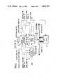
- FIG. 1is an overall block diagram of an optical recording and reproducing system in which the present invention may be incorporated.
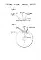
- FIG. 2illustrates the relative locations of the three laser beams provided by the system of FIG. 1 when focused on a selected track of the optical disk.
- FIG. 3is a block and schematic representation of the laser optical system shown in FIG. 1.
- FIG. 4is a schematic diagram generally illustrating the arrangement and formatting of data on the optical disk.
- FIG. 5is a schematic diagram illustrating details of the header formatting shown in FIG. 4.
- FIG. 6is a block electrical diagram illustrating a preferred implementation of the signal processing electronics of FIG. 1.
- FIG. 7is a cross-sectional view illustrating the construction of an optical disk employed in the system of FIG. 1.
- FIG. 8is a schematic illustration showing details of the optics employed in a preferred embodiment of the beam combiner and splitter 38 shown in FIG. 1.
- FIGS. 9 and 10are side and plan views, respectively, of the spatial combining and separating device 115 shown in FIG. 8.
- FIG. 11is a schematic illustration showing details of the focus detector 47 in FIG. 3.
- FIGS. 12-14are schematic diagrams illustrating the operation of the focus detector 47 shown in FIG. 11.
- FIG. 1generally illustrates the basic portions of the embodiment of an optical recording and reading system disclosed in the aforementioned commonly assigned copending patent applications.
- the data to be recordedis first applied to recording circuitry 10 which encodes the applied data using, for example, a conventional encoding format of the type employed for magnetic recording, such as non-return-to-zero, return-to-zero, etc. Conventional error checking may also be provided for the encoded signal.
- the encoded data 10a from the recording circuitry 10is applied to a laser optical system 12.
- the laser optical system 12generates three laser beams 12a, 12b and 12c which are focused at spaced locations along the center line of the same selected track of a preformatted optical disk 15 supported on a precision spindle 16 for rotation by a motor 18.
- the optical disk 15may, for example, be a trilayer disk of the type disclosed in the aforementioned U.S. Pat. No. 4,222,071 and in the aforementioned article by Bell, et al.
- Each laser beammay, for example, be focused to a one micron spot size on the disk 15.
- Laser beam 12ais a writing beam which is modulated by the encoded data so as to form optically detectable changes in a selected track of the optical disk 15 representative of the encoded data. It is to be understood that the optically detectable changes produced in the disk by the write laser beam 12a need not be physical changes, such as pits or physical holes. The only requirement is that optically detectable changes be produced in selected areas of the disk in response to the write laser beam 12a which are representative of the encoded data 10a. For the purpose of this description, all of the possible types of optically detectable changes that can be produced will hereinafter be referred to as optical holes.
- Laser beams 12b and 12c shown in FIG. 1are reading beams.
- the reading beam 12bis a read-after-write beam which is accordingly focused behind the writing beam 12a on the center line 17a of a selected track 17, while the reading beam 12b is a read-before-write beam and is accordingly focused ahead of the writing beam 12a.
- the intensity of the read beams 12b and 12care chosen so that they will not disturb the integrity of previously recorded information.
- the read beamsare reflected from the disk 15 back to the optical system 12 which, in response thereto, derives a plurality of detection signals 14a, 14b and 14c which are applied to signal processing electronics 20.
- the signal processing electronics 20also receives the encoded data signal 10a from the recording circuitry 10 for use in checking the accuracy of recorded data, as will hereinafter be considered.
- the signal processing electronics 20uses the detected signals 14a, 14b and 14c to provide an output data signal 20a corresponding to data read from the optical disk 15, along with signals 20b and 20c respectively identifying the track and sector locations on the disk from which the data is read.
- the signal processing electronics 20also produces control signals 10b, 21a, 21b, 21c, 21d, 21e and 21f.
- control signal 10bis applied to the recording circuitry 10 for synchronizing the encoding of data with disk rotation; control signal 21a is applied to the optical disk motor 18 to provide accurate speed control during recording and reading; control signal 21b is applied to the laser optical system 12 for controlling the radial position of the laser beams 12a, 12b and 12c for the purpose of selecting a desired track; control signal 21c is applied to the laser optical system 12 for providing precise track following of the laser beams on the selected track; control signal 21d is applied to the laser optical system 12 for providing precise focusing of the laser beams 12a, 12b and 12c; control signal 21e is applied to the recording circuitry 10 for interrupting recording if the reflected read-before-write beam indicates the possibility of an overwrite recording error because the track ahead contains previously recorded data; and signal 21f is applied to the recording circuitry 10 to interrupt recording if a recording error occurs.
- FIG. 3illustrates details of the laser optical system 12 generally shown in FIG. 1.
- the various components of this laser optical systemare illustrated in block and schematic form in FIG. 3 since their implementation can readily be provided by those skilled in the art, as will be evident from the aforementioned references.
- a laser 30provides a beam 30a having a wavelength of, for example, 633 nanometers and a power level of, for example, 12 mw.
- This laser beam 30ais applied to a first beam splitter 32 which splits the beam into a high power beam 32a and a low power beam 32b.
- the low power beam 32bis applied to a second beam splitter 34 which further splits the beam 32b to provide read-after-write and read-before-write beams 12b and 12c, respectively.
- a separate lasercould be employed for providing one or more of the above beams if so desired.
- the high power beam 32a in FIG. 3is applied to a high speed light-modulator 36 which modulates the beam 32a in response to the encoded data 10a provided at the output from the recording circuitry 10 in FIG. 1.
- This light-modulator 36may, for example, be an acousto-optical digital modulator.
- the resulting modulated high power beam at the output of the modulator 36is used as the write beam 12a of the system and is applied to a beam combiner and splitter 38 along with the read beams 12b and 12c which combines the beams taking into account their previously described spacing along the selected track of the disk 15 as typically illustrated in FIG. 2.
- the resulting three laser beams 12a, 12b and 12care then reflected off of a mirror 40 mounted to a galvanometer 42.
- the galvanometer 42is responsive to the control signal 21c from the signal processing electronics 20 (FIG. 1) so as to cause the mirror 40 to be appropriately deflected as required during track following and seeking operations.
- the laser beams 12a, 12b and 12care then directed to an objective lens assembly 44 mounted on a focusing motor 46.
- the motor 46operates in response to the control signal 21d from the signal processing electronics 20 in FIG. 1 to move the objective lens assembly 44 towards and away from the disk 15 so as to thereby maintain accurate focusing of the beams 12a, 12b and 12c on a selected track of the disk.
- Track selectionis provided by controlling the radial position of the beams 12a, 12b and 12c relative to the disk. This is accomplished using a linear motor 48 coupled to the objective lens assembly 44 and responsive to the control signal 21b from the signal processing electronics 20 in FIG. 1.
- the two read beams 12b and 12c shown in FIG. 3are reflected from the disk 15 with a reflected power which is modulated in accordance with the recorded pattern over which the beams pass.
- the reflected read beams 12b and 12cpass back to the beam combiner and splitter 38 via the objective lens assembly 44 and the galvanometer mirror 40.
- the beam combiner and splitter 38directs the reflected beams to optical detection circuitry 49 which converts the beams into corresponding read-after-write and read-before-write analog electrical signals 14a and 14b which are applied to the signal processing electronics 20 as shown in FIG. 1.
- At least one of the reflected read beams 12a and 12bis applied to a geometric optical focus detector 47 which provides a relatively low gain, wide capture range signal 14c to the signal processing electronics 20 which is indicative of the quality of focusing of the beams on the selected track.
- FIGS. 4 and 5An example of a typical preformatting arrangement is illustrated in FIGS. 4 and 5.
- the optical disk 15 in the preferred embodiment being describedcontains a large plurality of circumferential tracks 17, for example, 40,000 tracks spaced two microns apart on a 14-inch disk.
- the disk 15is also divided into a plurality of sectors 19.
- each track 17 within a sector 19comprises a header 51 and a data recording portion 52.
- the data recording portion 52is the portion into which data is written during recording and comprises the greater portion of the track length within each sector 19.
- the header 51 of a track 17is encountered first in each sector 19 and is provided on the disk prior to recording.
- a disk provided with such headers 51is typically referred to as being preformatted.
- FIG. 5illustrates an example of a preformatted header 51 provided for each track 17 in each sector 19 of the disk 15 of FIG. 3.
- the optical holes constituting the header 51need not be physically observable, as mentioned previously, it will be assumed for the purposes of this description that physical holes, such as pits, are employed for the exemplary header shown in FIG. 4. It will also be assumed that a pit exhibits a relatively high reflectance to an incident beam while other undisturbed disk areas exhibit a relatively low reflectance. It is to be understood that an arrangement may also be employed in which a portion of the optical recording is provided using physical holes, such as pits, and the remaining recorded portions are recorded using optical holes.
- FIG. 7illustrates a cross-section of a disk 15 which may be employed in the system of FIG. 1.
- a supporting substrate 90such as a 0.1 to 0.3 inch thick disk of aluminum is coated with an organic smoothing layer 92 of, for example, 20-60 microns prior to deposition thereon of a highly reflective opaque layer 94 of aluminum which may, for example, have a thickness of 400-800 Angstroms.
- An inorganic dielectric layer 96such as a 800-1200 Angstrom layer of silicon dioxide which is transparent at the laser frequency is deposited over the aluminum reflector layer 94.
- An absorbing layer 98which is absorptive at the laser frequency is then deposited over the dielectric layer 96.
- This absorbing layer 98may for example be a 50 to 300 Angstrom layer of a metal such as tellurium.
- a protective layer 100such as a silicon resin having a thickness of, for example, 150 to 500 microns.
- an anti-reflection (dark mirror) condition for a laser beam incident on unrecorded portions of the disk 15is produced by appropriately choosing the thicknesses and optical characteristics of the layers 94, 96 and 98.
- Recording on such a disk 15 as illustrated in FIG. 7is then accomplished by employing an appropriately focused, intensity-modulated recording laser beam (such as laser beam 12a in FIGS. 1 and 2) which records information by forming optically detectable changes, such as pits 98a, in the absorbing layer 98 along a selected track, the spacing and dimensions of these pits 98a being representative of the recorded data.
- Informationis read from the disk 15 using an appropriately focused reading laser beam (such as laser beams 12b and 12c in FIGS.
- the reflected reading beamwill be intensity modulated by the pits 98a since the reading beam will experience a relatively high reflection when the beam is incident on a pit 98a, and a relatively low reflection when the reading beam is incident on an unwritten region 98b. It will be understood that dust particles on the upper surface of the protective layer 100 will be far removed from the focal plane of the optical system (that is, they will be out of focus) so as to have a negligible effect on the above described recording and reading operations.
- header 51is used in conjunction with the signal processing electronics 20 in FIG. 1 to provide for reliable and precise operation of the system, it will be helpful to describe the construction and arrangement of the exemplary header 51 shown in FIG. 5 in conjunction with FIG. 6 which illustrates an implementation of the signal processing electronics 20 generally shown in FIG. 1.
- FIG. 6illustrates an implementation of the signal processing electronics 20 generally shown in FIG. 1.
- the individual components of FIG. 6can readily be implemented by those skilled in the art and are thus shown in block form.
- a relatively large pit 54providing a relatively large change in optical reflectance which is used to provide synchronized timing for the signal processing electronics 20.
- Thisis accomplished by applying the detected read-after-write signal 14a in FIG. 3 to a peak detector 73 via a preamplifier 71.
- the peak detector 73outputs a narrow pulse 73a corresponding to the pit 54 which it recognizes as the largest peak in the playback signal.
- This narrow output pulse 73a produced by the peak detector 73is then applied as a timing reference to conventional timing circuitry 75 which generates various timing signals 10b, 21a, 75a, 75b, 75c, 75d and 75e for synchronizing the operation of the system with the disk 15.
- timing circuitry 75which generates various timing signals 10b, 21a, 75a, 75b, 75c, 75d and 75e for synchronizing the operation of the system with the disk 15. The purposes of these timing signals will become evident as the description proceeds.
- pit 54 in FIG. 5Following pit 54 in FIG. 5 are two pits 56 and 58 elongated in a direction parallel to the track 17 and disposed on opposite sides of the track center line 17a in a staggered relationship. These pits 56 and 58 are used to provide precise track following. This is accomplished in FIG. 6 by applying the amplified read-after-write signal provided at the output of the preamplifier 71 to up-down integrator circuitry 77.
- the up-down integrator circuitry 77integrates up in response to the detected signal obtained when the read-after-write beam traverses the portion of the track 17 corresponding to the elongated pit 56, and integrates down in response to the signal obtained when the read-after-write beam traverses the portion of the track 17 corresponding to the elongated pit 58. It will be understood that the difference between these two integrations will be a measure of the preciseness of track following by the laser beams.
- the dimensions and locations of the elongated pits 56 and 58are chosen in conjunction with the size of the focused beam so that even very small deviations of the beam from the track center line 17a can be detected.
- the timing circuitry 75provides timing signals 75a and 75b to the up-down integrator circuitry 77.
- the timing signal 75ais used to delineate the particular times during traversal of the header 51 of each sector for which up and down integrations should be performed so as to appropriately correspond with the locations of the elongated pits 56 and 58.
- the timing signal 75bis provided during each sector to the up-down integrator circuitry 77 to serve as a hold signal to hold until the next sector the resultant integrated value obtained after the read-after-write beam has completed traversing the second elongated pit 58.
- a plurality of pits 60 elongated perpendicularly to the track center line 17aFollowing the elongated pits 56 and 58 in the exemplary header 51 shown in FIG. 5 are a plurality of pits 60 elongated perpendicularly to the track center line 17a.
- the locations and dimensions of the pits 60are chosen so that the reflected signal obtained upon traversing these pits 60 will have a peak value dependent upon the quality of focusing of the incident beam. This may be achieved, for example, by choosing the diameter of each pit 60 so that it is equal to the diameter of a properly focused beam. Then, if the incident beam is larger than the thickness of a pit 60 because of improper focusing, the reflected beam will have reduced power when each pit 60 is traversed, since only a portion of the beam will be reflected. It will also be understood that the spacing between the pits 60 along with the disk rotating speed determine the frequency at which the reflected beam is modulated when traversing the pits 60.
- a peak detector 64which is enabled by timing signal 75c during the period that the read-after-write beam is traversing the focusing pits 60, is provided to receive the amplified read-after-write beam at the output of the preamplifier 71.
- the peak detector 64is adapted to respond to the magnitude of the applied signal within a frequency range determined by the spacing of the pits 60 to produce a relatively high gain output signal 64a which is a measure of the quality of focusing.
- the output signal 64a from the peak detector 64is applied to a signal adder 66 along with the signal 14c provided by the optical focus detector 47 in FIG. 3.
- the signal adder 66appropriately combines these two signals 14c and 64a to produce the resulting signal 21d shown in FIG. 1 which is applied to the focusing motor 46 for maintaining precise focusing of the incident laser beams on the disk.
- the signal 14c obtained from the geometric optical focus detector 47 in FIG. 3provides only a relatively low gain control of the focusing distance which, while providing a wide capture range, typically results in producing a static or low frequency offset error.
- a significantly more precise and offset free focus signal 21dis achieved by combining the geometric optical detector signal 14c with the peak-detected signal 64a derived from the focusing holes 60 which is capable of providing a relatively high gain.
- the header 51is repeated a sufficient number of times around each circumferential track 17 to obtain the desired precise and fast-acting control of focusing as well as of track following.
- the above described focusing pits 60are followed by pits 72 recorded so as to provide an identification of the particular track and sector being traversed by the laser beams.
- the pits 72represent a track and sector address and conventional encoding can be employed for this purpose, such as is used for identifying tracks and sectors on magnetic disks.
- the amplified read-after-write signal at the output of the preamplifier 71is applied along with an appropriate enabling timing signal 75d to a track and sector decoder 78 which provides track and sector signals 20a and 20b respectively (see also FIG. 1) indicating the track and sector being traversed by the laser beams.
- the track signal 20bis also applied to track selection circuitry 80 along with a track command signal 80a indicative of a selected track to which it is desired that the laser beams be positioned.
- the track selection circuitry 80compares the track indicated by the track signal 20b with the track requested by the track command signal 80a and in response thereto produces the signal 21b which is applied to the linear motor 48 in FIG. 3 to center the laser beams over the selected track.
- the pits 72 which provide track and sector address identificationare the last portion of the header 51.
- the resulting disk containing these headersis considered to be preformatted.
- Such preformatted diskswill typically be provided to users who will make use of the preformatted headers in conjunction with signal processing electronics 20 such as illustrated in FIG. 6 for recording and reading data in the data recording portion 52 of each track 17 in each sector 19.
- the amplified read-after-write signal provided at the output of the preamplifier 71 in FIG. 6is also used for reading data from the data recording portion 51 of each sector 19 (FIGS. 4 and 5). Accordingly, the implementation of FIG. 6 includes data read circuitry 82 to which the output of the preamplifier 71 is applied for providing a data output signal 20a (see also FIG. 1) corresponding to the recorded digital data.
- the data read circuitry 82is enabled during the time period that the read-after-write beam is traversing the data portion 52 (FIG. 4) of each sector 19 by the timing signal 75e.
- the resulting data output signal 20a read from the disk 15is applied to an appropriate utilization device (not shown) along with the track and sector signals 20b and 20c which identify the track and sector from which data is read.
- the data output signal 20ais also used during data recording to check that data is accurately being recorded.
- FIG. 6includes a data comparator 83 which receives both the data output signal 20a and the encoded data signal 10a from the recording circuitry 10.
- the data comparator 83operates to compare the encoded data 10a with the corresponding data 20a read from the disk 15. If the comparator detects an error in the signals 10a and 20a, then the recording error interrupt signal 21f is produced which is applied to the recording circuitry 10 to interrupt recording.
- the read-before-write signal 14b obtained from the optical detection circuitry 49 in FIG. 3is applied to a preamplifier 91 whose output 91a is in turn applied to a data detector 95 via filter circuitry 93.
- the filter circuitry 93is provided to prevent noise from interfering with the operation of the data detector 95.
- the data detector 95is responsive to the presence of recorded data to produce an interrupt signal 95a which is applied to the recording circuitry 10 (FIG. 1) to halt recording, thereby protecting previously recorded data.
- the read-before-write beammay also be used for other purposes, such as to check the quality of the track prior to recording, or to provide more precise track following and/or focusing control.
- FIGS. 8-14illustrate particularly advantageous embodiments of the optics and photodetector elements employed in the beam combiner and splitter 38, the optical detector circuit 49 and the optical focus detector 47 shown in FIG. 3.
- the write beam 12a in FIG. 8corresponds to the write beam provided at the output of the light modulator 36 in FIG. 3, while the read beams 12b and 12c in FIG. 8 correspond to the read beams provided at the output of the beam splitter 34 in FIG. 3.
- the spacing of the read beams 12b and 12cis provided based on the spacing required therebetween when focused on the disk.
- the beams 12a, 12b and 12care polarized such that the write beam 12a has a polarization which is perpendicular to the polarization of the read beams 12b and 12c.
- the read beams 12b and 12care applied, via a focusing lens 112, to a beam splitter 110 which is constructed and arranged to reflect the read beams 12b and 12c to a specially designed spatial combining and separating device 115.
- the focusing lens 112serves to appropriately focus the read beams on the device 115.
- the write beam 12ais also applied to this spatial combining and separating device 115 via a focusing lens 117 which appropriately focuses the write beam 12a on the device 115.
- the construction, arrangement and operation of the spatial combining and separating device 115are such as to cause the applied write beam 12a to be transmitted therethrough while the applied read beams 12b and 12c are reflected therefrom so as to produce resulting write and read beams 12a', 12b' and 12c' having appropriate spacings corresponding to those required when the beams are focused on the disk (see FIG. 2). Also, the polarization of the write beam 12a' retains its perpendicular relationship with respect to the polarization of the read beams 12b' and 12c'.
- the construction and operation of a preferred embodiment of the spatial combining and separating device 115will be considered in detail later on herein with reference to FIGS. 9 and 10.
- the write and read beams 12a', 12b' and 12c' from the spatial combining and separating device 115 in FIG. 8are applied to a collimating lens 120 via a quarter wave plate 125 which produces resulting parallel read and write beams which respectively correspond to the beams 12a, 12b and 12c shown at the output of the spatial combiner and splitter 38 in FIG. 3.
- these read and write beamsare applied, via the galvanometer mirror 40 and the objective lens assembly 44, for focusing on the disk 15 (as shown in FIG. 2) with the galvanometer 42 providing for movement of the beams perpendicularly to the concentric tracks 17 (FIG. 4), as required for track following and track seeking.
- the optics of the systemare chosen such that, after reflection from the disk, the reflected read and write beams are again focused on the spatial combining and separating device 115 via the same path as followed by the transmitted beams.
- the returning read beamsare reflected (upwardly in FIG. 8) by the spatial combining and separating device 115 to the beam splitter 110, while the returning write beam is again transmitted through the device 115 so as not to interfere with the reflected read beams. Since the reflected read beams will have made two passes through the quarter wave plate 120, they will now pass through the beam splitter 110, as indicated by read beams 12b" and 12c" in FIG. 8.
- the reflected read beams 12b" and 12c" which pass through the beam splitter 110are respectively applied to photodetectors 124 and 126.
- the read beam 12b"passes to the photodetector 124 via a beam splitter 128, and the read beam 12c" passes to the photodetector 126 via a mirror 130.
- the resulting outputs from these photodetectors 124 and 126respectively correspond to the read-before-write and read-after-write outputs 14a and 14b shown in FIG. 3 from the optical detector 49.
- the portion of the reflected read beam 12b" which passes through the beam splitter 128is designated as 12b'" in FIG. 8 and corresponds to the beam 12b applied to the optical focus detector 47 in FIG. 3.
- a particularly advantageous embodiment of this optical focus detector 47will be considered in detail later on herein in connection with FIGS. 11-14.
- the device 115comprises a thin transparent element 150, such as glass, which may typically be of circular shape.
- the thickness of the element 150is preferably made very thin so as not to introduce astigmatism.
- a coating 152which is chosen in a conventional manner so as to act as an anti-reflective coating at the wavelength of the write beam 12a, thereby permitting the write beam 12a to pass through the element 115 with minimum reflection.
- the other side of the element 150 shown in FIGS. 9 and 10is provided with a reflective dielectric coating 154 which is chosen in a conventional manner so as to act as a mirror at the wavelength of the read beams 12b and 12c (which is usually the same as the write beam wavelength).
- the read beams 12b and 12c applied to the device 115will be reflected from the reflective coating 154 to become the read beams 12a' and 12b; and likewise, the returning read beams reflected from the disk will also be reflected from the reflective coating 154 of the device 115 to ultimately become the reflected read beams 12a" and 12b" from the beam splitter 110.
- the read and write beams reflected from the diskare not shown in FIG. 9.
- the slot area 155(on which the read beams do not impinge) is provided with an anti-reflective dielectric coating 156 (again in a conventional manner) at the wavelength of the write beam 12a so as to permit the write beam 12a to pass out from the device 115 to become the write beam 12a' shown in FIGS. 8 and 9, and so as to also permit the returning write beam reflected from the disk to pass back through the device 115 and out from the anti-reflective coating 152 at the other side of the device 115, as described previously.
- the location of the slot 155 in the spatial combining and separating device 115 shown in FIGS. 9 and 10is chosen to correspond to the appropriate location required for the write beam relative to the read beams, as shown in FIG. 2.
- FIG. 11illustrates the construction and arrangement of a preferred embodiment of the focus detector 47 in FIG. 3 to which the beam 12b'" in FIG. 9 is applied, as mentioned previously.
- the focus detector 47includes a lens 130 which collects the reflected read beam 12b'" and applies it to a collimating lens 132.
- the resulting parallel beam from lens 132is applied to a beam splitter 133 which splits the beam 12b'" into the two beams 12b-1 and 12b-2 which preferably are of approximately equal intensity.
- the beam 12b-1is applied to a photodetector 136 and the beam 12b-2 is applied to a photodetector 138.
- the resulting photodetector outputs 136a and 138aare applied to a difference amplifier 140 which in response thereto produces a focus error signal F (which corresponds to the signal 14c in FIG. 3).
- the construction, arrangement and locations of the photodetector elements 136 and 138are chosen so that: (1) when the read and write beams are properly in focus on the disk, the first and second photodetector outputs 136 and 138 will be equal, in which case the focus error signal F from the difference amplifier 40 is zero; (2) when the beams are out of focus in one direction, the first photodetector output will be greater than the second photodetector output by an amount dependent upon the magnitude of the out-of-focus distance, in which case the focus error signal F will have a first polarity; and (3) when the beams are out-of-focus in the opposite direction, the second photodetector output will be greater than the first photodetector output, in which case the focus error signal F will have the opposite polarity.
- FIGS. 12-14illustrate a functionally similar arrangement to that of FIG. 11 which, for the purpose of illustration, omits the beam splitter 133 and places the photodetectors 136 and 138 in line with the collimated beam (112a-1 or 112b-1) derived from the lens 132.
- the upper portion of each of FIGS. 12-14shows the relation of each of the beams 12b-1 and 12b-2 with respect to a schematic side view of their respective photodetectors 136 and 138, while the lower portion of each of FIGS. 12-14 shows the relation of each of the beams 12a-1 and 12-b with respect to a schematic plan view of their respective photodetectors 136 and 138.
- each of photodetectors 136 and 138includes a photosensitive element 136a or 138a of generally rectangular shape having a slot 136b or 138b.
- the photodetectors 136 and 138are located in their respective optical paths such that the incident respective beams 12b-1 and 12b-2 will be of substantially equal diameter when the beams are in proper focus on the disk. This is the situation illustrated in FIG. 12.
- FIGS. 13 and 14illustrate the effect of positive and negative out-of-focus conditions.
- FIG. 13illustrates the condition for which the spacing between the objective lens assembly 44 in FIG. 3 and the optical disk 15 is greater than its in-focus distance
- FIG. 14illustrates the condition for which the spacing between the objective lens assembly 44 and the disk 15 is less than the in-focus distance. It will be seen that for a spacing greater than the in-focus distance, as illustrated in FIG. 13, a converging, wider than normal beam is obtained from the lens 132 which results in a correspondingly wider beam being applied to the photodetector 136 and a correspondingly narrower beam being applied to the photodetector 138.
- FIGS. 12-14 for the focus detector 47is preferably achieved by designing the optics in accordance with the equation: ##EQU1## where f 0 is the focal length provided by the objective lens assembly 44 in FIG. 3, f 3 is the focal length of the lens 120 in FIG. 11, f 6 is the effective focal length of lenses 130 and 132 in FIG. 11, S 1 is the distance between the lens 132 and the photodetector 12b-1, and S 2 is the distance between the lens 132 and the photodetector 12b-2.
- each of the photodetector slots 136b and 138bso as to be equal to approximately one-half of the diameter of their respective beams 12b-1 and 12b-2 for the in-focus condition shown in FIG. 12.
- An important advantage of providing an optical arrangement as described aboveis that the focus error signal F produced at the output of the difference amplifier 140 in FIG. 11 will have only one zero-crossing point which will substantially coincide with the desired in-focus condition. Additional advantages are that a high gain can be obtained in the immediate vicinity of the zero-crossing point along with a relatively wide capture range.
- the size of the photosensitive elements 136a and 136b and the length of the slots 136b and 138b provided thereinbe chosen so as to be sufficient to accommodate the maximum excursion which could occur in the beams 12b-1 and 12b-2 as a result of the operation of the galvanometer 42 in FIG. 3.
Landscapes
- Physics & Mathematics (AREA)
- Optics & Photonics (AREA)
- Optical Recording Or Reproduction (AREA)
Abstract
Description
______________________________________ U.S. PATENT DOCUMENTS U.S. Pat. No. Date Issued Inventor(s) ______________________________________ 4,216,501 8/5/80 Bell 4,219,848 8/26/80 Spong 4,222,071 9/9/80 Bell, et al. 4,232,337 12/4/80 Winslow, et al. 4,243,848 1/6/81 Utsumi 4,243,850 1/6/81 Edwards 4,253,019 2/24/81 Opheij 4,253,723 3/3/81 Kojima, et al. 4,253,734 3/3/81 Komurasaki 4,268,745 5/19/81 Okano 4,287,413 9/1/81 Kanamaru 4,290,132 9/15/81 Kotaka ______________________________________
Claims (10)
Priority Applications (1)
| Application Number | Priority Date | Filing Date | Title |
|---|---|---|---|
| US06/416,770US4621353A (en) | 1982-09-09 | 1982-09-09 | Optical memory system providing improved focusing control and improved beam combining and separating apparatus |
Applications Claiming Priority (1)
| Application Number | Priority Date | Filing Date | Title |
|---|---|---|---|
| US06/416,770US4621353A (en) | 1982-09-09 | 1982-09-09 | Optical memory system providing improved focusing control and improved beam combining and separating apparatus |
Publications (1)
| Publication Number | Publication Date |
|---|---|
| US4621353Atrue US4621353A (en) | 1986-11-04 |
Family
ID=23651231
Family Applications (1)
| Application Number | Title | Priority Date | Filing Date |
|---|---|---|---|
| US06/416,770Expired - LifetimeUS4621353A (en) | 1982-09-09 | 1982-09-09 | Optical memory system providing improved focusing control and improved beam combining and separating apparatus |
Country Status (1)
| Country | Link |
|---|---|
| US (1) | US4621353A (en) |
Cited By (37)
| Publication number | Priority date | Publication date | Assignee | Title |
|---|---|---|---|---|
| EP0319033A3 (en)* | 1987-12-02 | 1991-06-12 | Hitachi, Ltd. | Method for detecting focus error using light beams having astigmatism and optical information processing system using this method. |
| EP0426053A3 (en)* | 1989-10-30 | 1991-12-18 | Nippon Conlux Co., Ltd. | Optical head for optical information recording medium |
| US5220550A (en)* | 1990-08-10 | 1993-06-15 | Alps Electric Co., Ltd. | Optical beam system for optical disk drives |
| US5338924A (en)* | 1992-08-11 | 1994-08-16 | Lasa Industries, Inc. | Apparatus and method for automatic focusing of light using a fringe plate |
| US5493554A (en)* | 1992-10-20 | 1996-02-20 | Hitachi, Ltd. | 2-laser optical head and recording/reproducing apparatus |
| US20100305452A1 (en)* | 2009-05-28 | 2010-12-02 | Black John F | Optical coherence tomography for biological imaging |
| US8548571B2 (en) | 2009-12-08 | 2013-10-01 | Avinger, Inc. | Devices and methods for predicting and preventing restenosis |
| US8644913B2 (en) | 2011-03-28 | 2014-02-04 | Avinger, Inc. | Occlusion-crossing devices, imaging, and atherectomy devices |
| US8696695B2 (en) | 2009-04-28 | 2014-04-15 | Avinger, Inc. | Guidewire positioning catheter |
| US9125562B2 (en) | 2009-07-01 | 2015-09-08 | Avinger, Inc. | Catheter-based off-axis optical coherence tomography imaging system |
| US9345398B2 (en) | 2012-05-14 | 2016-05-24 | Avinger, Inc. | Atherectomy catheter drive assemblies |
| US9345406B2 (en) | 2011-11-11 | 2016-05-24 | Avinger, Inc. | Occlusion-crossing devices, atherectomy devices, and imaging |
| US9345510B2 (en) | 2010-07-01 | 2016-05-24 | Avinger, Inc. | Atherectomy catheters with longitudinally displaceable drive shafts |
| US9498600B2 (en) | 2009-07-01 | 2016-11-22 | Avinger, Inc. | Atherectomy catheter with laterally-displaceable tip |
| US9498247B2 (en) | 2014-02-06 | 2016-11-22 | Avinger, Inc. | Atherectomy catheters and occlusion crossing devices |
| US9557156B2 (en) | 2012-05-14 | 2017-01-31 | Avinger, Inc. | Optical coherence tomography with graded index fiber for biological imaging |
| US9592075B2 (en) | 2014-02-06 | 2017-03-14 | Avinger, Inc. | Atherectomy catheters devices having multi-channel bushings |
| US9854979B2 (en) | 2013-03-15 | 2018-01-02 | Avinger, Inc. | Chronic total occlusion crossing devices with imaging |
| US9918734B2 (en) | 2008-04-23 | 2018-03-20 | Avinger, Inc. | Catheter system and method for boring through blocked vascular passages |
| US9949754B2 (en) | 2011-03-28 | 2018-04-24 | Avinger, Inc. | Occlusion-crossing devices |
| US10130386B2 (en) | 2013-07-08 | 2018-11-20 | Avinger, Inc. | Identification of elastic lamina to guide interventional therapy |
| US10335173B2 (en) | 2012-09-06 | 2019-07-02 | Avinger, Inc. | Re-entry stylet for catheter |
| US10357277B2 (en) | 2014-07-08 | 2019-07-23 | Avinger, Inc. | High speed chronic total occlusion crossing devices |
| US10363062B2 (en) | 2011-10-17 | 2019-07-30 | Avinger, Inc. | Atherectomy catheters and non-contact actuation mechanism for catheters |
| US10548478B2 (en) | 2010-07-01 | 2020-02-04 | Avinger, Inc. | Balloon atherectomy catheters with imaging |
| US10568520B2 (en) | 2015-07-13 | 2020-02-25 | Avinger, Inc. | Micro-molded anamorphic reflector lens for image guided therapeutic/diagnostic catheters |
| US10932670B2 (en) | 2013-03-15 | 2021-03-02 | Avinger, Inc. | Optical pressure sensor assembly |
| US11096717B2 (en) | 2013-03-15 | 2021-08-24 | Avinger, Inc. | Tissue collection device for catheter |
| US11224459B2 (en) | 2016-06-30 | 2022-01-18 | Avinger, Inc. | Atherectomy catheter with shapeable distal tip |
| US11278248B2 (en) | 2016-01-25 | 2022-03-22 | Avinger, Inc. | OCT imaging catheter with lag correction |
| US11284916B2 (en) | 2012-09-06 | 2022-03-29 | Avinger, Inc. | Atherectomy catheters and occlusion crossing devices |
| US11344327B2 (en) | 2016-06-03 | 2022-05-31 | Avinger, Inc. | Catheter device with detachable distal end |
| US11382653B2 (en) | 2010-07-01 | 2022-07-12 | Avinger, Inc. | Atherectomy catheter |
| US11399863B2 (en) | 2016-04-01 | 2022-08-02 | Avinger, Inc. | Atherectomy catheter with serrated cutter |
| US11406412B2 (en) | 2012-05-14 | 2022-08-09 | Avinger, Inc. | Atherectomy catheters with imaging |
| US11793400B2 (en) | 2019-10-18 | 2023-10-24 | Avinger, Inc. | Occlusion-crossing devices |
| US12167867B2 (en) | 2018-04-19 | 2024-12-17 | Avinger, Inc. | Occlusion-crossing devices |
Citations (18)
| Publication number | Priority date | Publication date | Assignee | Title |
|---|---|---|---|---|
| US3719421A (en)* | 1970-12-10 | 1973-03-06 | Compteurs Comp D | Optical device for determining the position of a point on a surface |
| US3925603A (en)* | 1973-06-11 | 1975-12-09 | Sony Corp | Apparatus for recording and/or reproducing information signals having automatic focusing |
| US3997715A (en)* | 1974-03-25 | 1976-12-14 | Mca Disco-Vision, Inc. | Focusing system for videodisc player |
| US4051527A (en)* | 1976-01-28 | 1977-09-27 | U.S. Philips Corporation | Focus detection system for a video disc player using a plurality of radiation sensors in the far field of the information structure |
| US4085423A (en)* | 1975-06-06 | 1978-04-18 | Hitachi, Ltd. | Information reproducing apparatus with plural beam readout |
| US4097730A (en)* | 1975-07-02 | 1978-06-27 | Zenith Radio Corporation | Focus correction system for video disc player |
| US4123652A (en)* | 1977-03-22 | 1978-10-31 | U.S. Philips Corporation | Apparatus for reading a radiation-reflecting record carrier |
| US4152586A (en)* | 1977-06-06 | 1979-05-01 | Mca Discovision, Inc. | Optical transducer and focusing system |
| US4163149A (en)* | 1976-07-28 | 1979-07-31 | Hitachi, Ltd. | Automatic focusing apparatus |
| US4290122A (en)* | 1979-05-14 | 1981-09-15 | Xerox Corporation | Self-synchronizing clock source for optical memories |
| US4357533A (en)* | 1980-07-14 | 1982-11-02 | Discovision Associates | Focus detector for an optical disc playback system |
| US4363116A (en)* | 1978-03-16 | 1982-12-07 | U.S. Philips Corporation | Method, apparatus and record carrier body for optically writing information |
| US4365323A (en)* | 1976-08-02 | 1982-12-21 | U.S. Philips Corporation | Optic read unit for scanning a record carrier having a radiation-reflecting information structure |
| US4399529A (en)* | 1980-05-28 | 1983-08-16 | Thomson-Csf | Optical device for recording and reading on a data carrier |
| US4402061A (en)* | 1981-10-15 | 1983-08-30 | Burroughs Corporation | Preformatted optical media for use in an optical memory system |
| US4417330A (en)* | 1981-10-15 | 1983-11-22 | Burroughs Corporation | Optical memory system providing improved focusing control |
| US4559622A (en)* | 1982-09-09 | 1985-12-17 | Burroughs Corporation | Optical memory system providing improved focus detection and control by detecting reflected beam diameter variations at spaced predetermined locations in the system |
| US4562568A (en)* | 1982-09-09 | 1985-12-31 | Burroughs Corporation | Beam combining and separating apparatus useful for combining and separating reading and writing laser beams in an optical storage system |
- 1982
- 1982-09-09USUS06/416,770patent/US4621353A/ennot_activeExpired - Lifetime
Patent Citations (18)
| Publication number | Priority date | Publication date | Assignee | Title |
|---|---|---|---|---|
| US3719421A (en)* | 1970-12-10 | 1973-03-06 | Compteurs Comp D | Optical device for determining the position of a point on a surface |
| US3925603A (en)* | 1973-06-11 | 1975-12-09 | Sony Corp | Apparatus for recording and/or reproducing information signals having automatic focusing |
| US3997715A (en)* | 1974-03-25 | 1976-12-14 | Mca Disco-Vision, Inc. | Focusing system for videodisc player |
| US4085423A (en)* | 1975-06-06 | 1978-04-18 | Hitachi, Ltd. | Information reproducing apparatus with plural beam readout |
| US4097730A (en)* | 1975-07-02 | 1978-06-27 | Zenith Radio Corporation | Focus correction system for video disc player |
| US4051527A (en)* | 1976-01-28 | 1977-09-27 | U.S. Philips Corporation | Focus detection system for a video disc player using a plurality of radiation sensors in the far field of the information structure |
| US4163149A (en)* | 1976-07-28 | 1979-07-31 | Hitachi, Ltd. | Automatic focusing apparatus |
| US4365323A (en)* | 1976-08-02 | 1982-12-21 | U.S. Philips Corporation | Optic read unit for scanning a record carrier having a radiation-reflecting information structure |
| US4123652A (en)* | 1977-03-22 | 1978-10-31 | U.S. Philips Corporation | Apparatus for reading a radiation-reflecting record carrier |
| US4152586A (en)* | 1977-06-06 | 1979-05-01 | Mca Discovision, Inc. | Optical transducer and focusing system |
| US4363116A (en)* | 1978-03-16 | 1982-12-07 | U.S. Philips Corporation | Method, apparatus and record carrier body for optically writing information |
| US4290122A (en)* | 1979-05-14 | 1981-09-15 | Xerox Corporation | Self-synchronizing clock source for optical memories |
| US4399529A (en)* | 1980-05-28 | 1983-08-16 | Thomson-Csf | Optical device for recording and reading on a data carrier |
| US4357533A (en)* | 1980-07-14 | 1982-11-02 | Discovision Associates | Focus detector for an optical disc playback system |
| US4402061A (en)* | 1981-10-15 | 1983-08-30 | Burroughs Corporation | Preformatted optical media for use in an optical memory system |
| US4417330A (en)* | 1981-10-15 | 1983-11-22 | Burroughs Corporation | Optical memory system providing improved focusing control |
| US4559622A (en)* | 1982-09-09 | 1985-12-17 | Burroughs Corporation | Optical memory system providing improved focus detection and control by detecting reflected beam diameter variations at spaced predetermined locations in the system |
| US4562568A (en)* | 1982-09-09 | 1985-12-31 | Burroughs Corporation | Beam combining and separating apparatus useful for combining and separating reading and writing laser beams in an optical storage system |
Cited By (81)
| Publication number | Priority date | Publication date | Assignee | Title |
|---|---|---|---|---|
| EP0319033A3 (en)* | 1987-12-02 | 1991-06-12 | Hitachi, Ltd. | Method for detecting focus error using light beams having astigmatism and optical information processing system using this method. |
| EP0426053A3 (en)* | 1989-10-30 | 1991-12-18 | Nippon Conlux Co., Ltd. | Optical head for optical information recording medium |
| US5220550A (en)* | 1990-08-10 | 1993-06-15 | Alps Electric Co., Ltd. | Optical beam system for optical disk drives |
| US5338924A (en)* | 1992-08-11 | 1994-08-16 | Lasa Industries, Inc. | Apparatus and method for automatic focusing of light using a fringe plate |
| US5493554A (en)* | 1992-10-20 | 1996-02-20 | Hitachi, Ltd. | 2-laser optical head and recording/reproducing apparatus |
| US9572492B2 (en) | 2008-04-23 | 2017-02-21 | Avinger, Inc. | Occlusion-crossing devices, imaging, and atherectomy devices |
| US10869685B2 (en) | 2008-04-23 | 2020-12-22 | Avinger, Inc. | Catheter system and method for boring through blocked vascular passages |
| US9918734B2 (en) | 2008-04-23 | 2018-03-20 | Avinger, Inc. | Catheter system and method for boring through blocked vascular passages |
| US11998311B2 (en) | 2009-04-28 | 2024-06-04 | Avinger, Inc. | Guidewire positioning catheter |
| US8696695B2 (en) | 2009-04-28 | 2014-04-15 | Avinger, Inc. | Guidewire positioning catheter |
| US9642646B2 (en) | 2009-04-28 | 2017-05-09 | Avinger, Inc. | Guidewire positioning catheter |
| US11076773B2 (en) | 2009-04-28 | 2021-08-03 | Avinger, Inc. | Guidewire positioning catheter |
| US10342491B2 (en) | 2009-05-28 | 2019-07-09 | Avinger, Inc. | Optical coherence tomography for biological imaging |
| US9788790B2 (en)* | 2009-05-28 | 2017-10-17 | Avinger, Inc. | Optical coherence tomography for biological imaging |
| US20100305452A1 (en)* | 2009-05-28 | 2010-12-02 | Black John F | Optical coherence tomography for biological imaging |
| US12178613B2 (en) | 2009-05-28 | 2024-12-31 | Avinger, Inc. | Optical coherence tomography for biological imaging |
| US11284839B2 (en) | 2009-05-28 | 2022-03-29 | Avinger, Inc. | Optical coherence tomography for biological imaging |
| US11839493B2 (en) | 2009-05-28 | 2023-12-12 | Avinger, Inc. | Optical coherence tomography for biological imaging |
| US11717314B2 (en) | 2009-07-01 | 2023-08-08 | Avinger, Inc. | Atherectomy catheter with laterally-displaceable tip |
| US9498600B2 (en) | 2009-07-01 | 2016-11-22 | Avinger, Inc. | Atherectomy catheter with laterally-displaceable tip |
| US12089868B2 (en) | 2009-07-01 | 2024-09-17 | Avinger, Inc. | Methods of using atherectomy catheter with deflectable distal tip |
| US10729326B2 (en) | 2009-07-01 | 2020-08-04 | Avinger, Inc. | Catheter-based off-axis optical coherence tomography imaging system |
| US9125562B2 (en) | 2009-07-01 | 2015-09-08 | Avinger, Inc. | Catheter-based off-axis optical coherence tomography imaging system |
| US10052125B2 (en) | 2009-07-01 | 2018-08-21 | Avinger, Inc. | Atherectomy catheter with laterally-displaceable tip |
| US12053260B2 (en) | 2009-07-01 | 2024-08-06 | Avinger, Inc. | Catheter-based off-axis optical coherence tomography imaging system |
| US8548571B2 (en) | 2009-12-08 | 2013-10-01 | Avinger, Inc. | Devices and methods for predicting and preventing restenosis |
| US10349974B2 (en) | 2010-07-01 | 2019-07-16 | Avinger, Inc. | Atherectomy catheters with longitudinally displaceable drive shafts |
| US10548478B2 (en) | 2010-07-01 | 2020-02-04 | Avinger, Inc. | Balloon atherectomy catheters with imaging |
| US11382653B2 (en) | 2010-07-01 | 2022-07-12 | Avinger, Inc. | Atherectomy catheter |
| US9345510B2 (en) | 2010-07-01 | 2016-05-24 | Avinger, Inc. | Atherectomy catheters with longitudinally displaceable drive shafts |
| US8644913B2 (en) | 2011-03-28 | 2014-02-04 | Avinger, Inc. | Occlusion-crossing devices, imaging, and atherectomy devices |
| US11903677B2 (en) | 2011-03-28 | 2024-02-20 | Avinger, Inc. | Occlusion-crossing devices, imaging, and atherectomy devices |
| US12137931B2 (en) | 2011-03-28 | 2024-11-12 | Avinger, Inc. | Occlusion-crossing devices |
| US11134849B2 (en) | 2011-03-28 | 2021-10-05 | Avinger, Inc. | Occlusion-crossing devices, imaging, and atherectomy devices |
| US9949754B2 (en) | 2011-03-28 | 2018-04-24 | Avinger, Inc. | Occlusion-crossing devices |
| US12257029B2 (en) | 2011-03-28 | 2025-03-25 | Avinger, Inc. | Occlusion-crossing devices, imaging, and atherectomy devices |
| US10952763B2 (en) | 2011-03-28 | 2021-03-23 | Avinger, Inc. | Occlusion-crossing devices |
| US10363062B2 (en) | 2011-10-17 | 2019-07-30 | Avinger, Inc. | Atherectomy catheters and non-contact actuation mechanism for catheters |
| US11135019B2 (en) | 2011-11-11 | 2021-10-05 | Avinger, Inc. | Occlusion-crossing devices, atherectomy devices, and imaging |
| US9345406B2 (en) | 2011-11-11 | 2016-05-24 | Avinger, Inc. | Occlusion-crossing devices, atherectomy devices, and imaging |
| US12257003B2 (en) | 2011-11-11 | 2025-03-25 | Avinger, Inc. | Occlusion-crossing devices, atherectomy devices, and imaging |
| US10952615B2 (en) | 2012-05-14 | 2021-03-23 | Avinger, Inc. | Optical coherence tomography with graded index fiber for biological imaging |
| US9345398B2 (en) | 2012-05-14 | 2016-05-24 | Avinger, Inc. | Atherectomy catheter drive assemblies |
| US9557156B2 (en) | 2012-05-14 | 2017-01-31 | Avinger, Inc. | Optical coherence tomography with graded index fiber for biological imaging |
| US12171407B2 (en) | 2012-05-14 | 2024-12-24 | Avinger, Inc. | Atherectomy catheter drive assemblies |
| US10244934B2 (en) | 2012-05-14 | 2019-04-02 | Avinger, Inc. | Atherectomy catheter drive assemblies |
| US11206975B2 (en) | 2012-05-14 | 2021-12-28 | Avinger, Inc. | Atherectomy catheter drive assemblies |
| US11647905B2 (en) | 2012-05-14 | 2023-05-16 | Avinger, Inc. | Optical coherence tomography with graded index fiber for biological imaging |
| US11406412B2 (en) | 2012-05-14 | 2022-08-09 | Avinger, Inc. | Atherectomy catheters with imaging |
| US11284916B2 (en) | 2012-09-06 | 2022-03-29 | Avinger, Inc. | Atherectomy catheters and occlusion crossing devices |
| US10335173B2 (en) | 2012-09-06 | 2019-07-02 | Avinger, Inc. | Re-entry stylet for catheter |
| US11980386B2 (en) | 2013-03-15 | 2024-05-14 | Avinger, Inc. | Tissue collection device for catheter |
| US11890076B2 (en) | 2013-03-15 | 2024-02-06 | Avinger, Inc. | Chronic total occlusion crossing devices with imaging |
| US10932670B2 (en) | 2013-03-15 | 2021-03-02 | Avinger, Inc. | Optical pressure sensor assembly |
| US11096717B2 (en) | 2013-03-15 | 2021-08-24 | Avinger, Inc. | Tissue collection device for catheter |
| US9854979B2 (en) | 2013-03-15 | 2018-01-02 | Avinger, Inc. | Chronic total occlusion crossing devices with imaging |
| US10722121B2 (en) | 2013-03-15 | 2020-07-28 | Avinger, Inc. | Chronic total occlusion crossing devices with imaging |
| US11723538B2 (en) | 2013-03-15 | 2023-08-15 | Avinger, Inc. | Optical pressure sensor assembly |
| US10806484B2 (en) | 2013-07-08 | 2020-10-20 | Avinger, Inc. | Identification of elastic lamina to guide interventional therapy |
| US10130386B2 (en) | 2013-07-08 | 2018-11-20 | Avinger, Inc. | Identification of elastic lamina to guide interventional therapy |
| US11944342B2 (en) | 2013-07-08 | 2024-04-02 | Avinger, Inc. | Identification of elastic lamina to guide interventional therapy |
| US10470795B2 (en) | 2014-02-06 | 2019-11-12 | Avinger, Inc. | Atherectomy catheters and occlusion crossing devices |
| US9498247B2 (en) | 2014-02-06 | 2016-11-22 | Avinger, Inc. | Atherectomy catheters and occlusion crossing devices |
| US10568655B2 (en) | 2014-02-06 | 2020-02-25 | Avinger, Inc. | Atherectomy catheters devices having multi-channel bushings |
| US9592075B2 (en) | 2014-02-06 | 2017-03-14 | Avinger, Inc. | Atherectomy catheters devices having multi-channel bushings |
| US10357277B2 (en) | 2014-07-08 | 2019-07-23 | Avinger, Inc. | High speed chronic total occlusion crossing devices |
| US11147583B2 (en) | 2014-07-08 | 2021-10-19 | Avinger, Inc. | High speed chronic total occlusion crossing devices |
| US11931061B2 (en) | 2014-07-08 | 2024-03-19 | Avinger, Inc. | High speed chronic total occlusion crossing devices |
| US11974830B2 (en) | 2015-07-13 | 2024-05-07 | Avinger, Inc. | Micro-molded anamorphic reflector lens for image guided therapeutic/diagnostic catheters |
| US11033190B2 (en) | 2015-07-13 | 2021-06-15 | Avinger, Inc. | Micro-molded anamorphic reflector lens for image guided therapeutic/diagnostic catheters |
| US10568520B2 (en) | 2015-07-13 | 2020-02-25 | Avinger, Inc. | Micro-molded anamorphic reflector lens for image guided therapeutic/diagnostic catheters |
| US11627881B2 (en) | 2015-07-13 | 2023-04-18 | Avinger, Inc. | Micro-molded anamorphic reflector lens for image guided therapeutic/diagnostic catheters |
| US11278248B2 (en) | 2016-01-25 | 2022-03-22 | Avinger, Inc. | OCT imaging catheter with lag correction |
| US11957376B2 (en) | 2016-04-01 | 2024-04-16 | Avinger, Inc. | Atherectomy catheter with serrated cutter |
| US11399863B2 (en) | 2016-04-01 | 2022-08-02 | Avinger, Inc. | Atherectomy catheter with serrated cutter |
| US11344327B2 (en) | 2016-06-03 | 2022-05-31 | Avinger, Inc. | Catheter device with detachable distal end |
| US12279789B2 (en) | 2016-06-03 | 2025-04-22 | Avinger, Inc. | Catheter device with detachable distal end |
| US11224459B2 (en) | 2016-06-30 | 2022-01-18 | Avinger, Inc. | Atherectomy catheter with shapeable distal tip |
| US12161360B2 (en) | 2016-06-30 | 2024-12-10 | Avinger, Inc. | Atherectomy catheter with shaped distal tip |
| US12167867B2 (en) | 2018-04-19 | 2024-12-17 | Avinger, Inc. | Occlusion-crossing devices |
| US11793400B2 (en) | 2019-10-18 | 2023-10-24 | Avinger, Inc. | Occlusion-crossing devices |
Similar Documents
| Publication | Publication Date | Title |
|---|---|---|
| US4621353A (en) | Optical memory system providing improved focusing control and improved beam combining and separating apparatus | |
| US4443870A (en) | Optical memory system providing track following | |
| US4402061A (en) | Preformatted optical media for use in an optical memory system | |
| US4494226A (en) | Three beam optical memory system | |
| US4417330A (en) | Optical memory system providing improved focusing control | |
| US4451915A (en) | Optical storage system employing a multi-layer optical medium | |
| US4432083A (en) | Optical memory system having track following | |
| US4428075A (en) | Methods of preformatting an optical disk | |
| US4432082A (en) | Optical memory system having a long seek capability | |
| US4451914A (en) | Optical storage system employing a multi-layer optical medium | |
| US4428069A (en) | Apparatus for preformatting an optical disk | |
| US4489406A (en) | Optical memory system having a short seek capability | |
| US4435797A (en) | Optical memory system having track following and seeking capabilities | |
| US4674076A (en) | Optical memory system having improved positioning and focusing control circuitry | |
| US4562568A (en) | Beam combining and separating apparatus useful for combining and separating reading and writing laser beams in an optical storage system | |
| US4888759A (en) | Laser optical memory system having beam combining and separating apparatus for combining and separating reading and writing laser beams | |
| US4669074A (en) | Focusing control circuitry for an optical memory system | |
| US4559622A (en) | Optical memory system providing improved focus detection and control by detecting reflected beam diameter variations at spaced predetermined locations in the system | |
| EP0096969A1 (en) | Optical memory system having improved positioning and focusing control circuitry | |
| US4622659A (en) | Focus detection and control apparatus for maintaining accurate focusing in an optical memory system by detecting reflected beam diameter variations at spaced predetermined locations |
Legal Events
| Date | Code | Title | Description |
|---|---|---|---|
| AS | Assignment | Owner name:BURROUGHS CORPORATION, DETROIT, MI., A CORP. OF MI Free format text:ASSIGNMENT OF ASSIGNORS INTEREST.;ASSIGNORS:HAZEL, ROBERT L.;CHAN, GILBERT YH;REEL/FRAME:004066/0513 Effective date:19820831 | |
| AS | Assignment | Owner name:BURROUGHS CORPORATION Free format text:MERGER;ASSIGNORS:BURROUGHS CORPORATION A CORP OF MI (MERGED INTO);BURROUGHS DELAWARE INCORPORATED A DE CORP. (CHANGED TO);REEL/FRAME:004312/0324 Effective date:19840530 | |
| STCF | Information on status: patent grant | Free format text:PATENTED CASE | |
| CC | Certificate of correction | ||
| AS | Assignment | Owner name:UNISYS CORPORATION, PENNSYLVANIA Free format text:MERGER;ASSIGNOR:BURROUGHS CORPORATION;REEL/FRAME:005012/0501 Effective date:19880509 | |
| FPAY | Fee payment | Year of fee payment:4 | |
| FEPP | Fee payment procedure | Free format text:PAYOR NUMBER ASSIGNED (ORIGINAL EVENT CODE: ASPN); ENTITY STATUS OF PATENT OWNER: LARGE ENTITY | |
| FPAY | Fee payment | Year of fee payment:8 | |
| FPAY | Fee payment | Year of fee payment:12 |