US4620835A - Pump protection system - Google Patents
Pump protection systemDownload PDFInfo
- Publication number
- US4620835A US4620835AUS06/616,110US61611084AUS4620835AUS 4620835 AUS4620835 AUS 4620835AUS 61611084 AUS61611084 AUS 61611084AUS 4620835 AUS4620835 AUS 4620835A
- Authority
- US
- United States
- Prior art keywords
- pump
- switch
- signal
- protection system
- sensor
- Prior art date
- Legal status (The legal status is an assumption and is not a legal conclusion. Google has not performed a legal analysis and makes no representation as to the accuracy of the status listed.)
- Expired - Lifetime
Links
- 238000009877renderingMethods0.000claimsdescription7
- 239000007788liquidSubstances0.000claimsdescription5
- 238000009434installationMethods0.000claimsdescription3
- 101100360207Caenorhabditis elegans rla-1 geneProteins0.000abstractdescription5
- 230000002035prolonged effectEffects0.000abstractdescription3
- XLYOFNOQVPJJNP-UHFFFAOYSA-NwaterSubstancesOXLYOFNOQVPJJNP-UHFFFAOYSA-N0.000description23
- 230000007935neutral effectEffects0.000description2
- 238000013021overheatingMethods0.000description2
- 229920003023plasticPolymers0.000description2
- 239000004033plasticSubstances0.000description2
- 238000005086pumpingMethods0.000description2
- 230000003068static effectEffects0.000description2
- 238000003287bathingMethods0.000description1
- 239000004020conductorSubstances0.000description1
- 238000010276constructionMethods0.000description1
- 230000000994depressogenic effectEffects0.000description1
- 230000009977dual effectEffects0.000description1
- 230000000694effectsEffects0.000description1
- 238000000034methodMethods0.000description1
- 230000009182swimmingEffects0.000description1
Images


Classifications
- F—MECHANICAL ENGINEERING; LIGHTING; HEATING; WEAPONS; BLASTING
- F04—POSITIVE - DISPLACEMENT MACHINES FOR LIQUIDS; PUMPS FOR LIQUIDS OR ELASTIC FLUIDS
- F04B—POSITIVE-DISPLACEMENT MACHINES FOR LIQUIDS; PUMPS
- F04B49/00—Control, e.g. of pump delivery, or pump pressure of, or safety measures for, machines, pumps, or pumping installations, not otherwise provided for, or of interest apart from, groups F04B1/00 - F04B47/00
- F04B49/06—Control using electricity
- F—MECHANICAL ENGINEERING; LIGHTING; HEATING; WEAPONS; BLASTING
- F04—POSITIVE - DISPLACEMENT MACHINES FOR LIQUIDS; PUMPS FOR LIQUIDS OR ELASTIC FLUIDS
- F04B—POSITIVE-DISPLACEMENT MACHINES FOR LIQUIDS; PUMPS
- F04B49/00—Control, e.g. of pump delivery, or pump pressure of, or safety measures for, machines, pumps, or pumping installations, not otherwise provided for, or of interest apart from, groups F04B1/00 - F04B47/00
- F04B49/02—Stopping, starting, unloading or idling control
- F04B49/022—Stopping, starting, unloading or idling control by means of pressure
- F—MECHANICAL ENGINEERING; LIGHTING; HEATING; WEAPONS; BLASTING
- F04—POSITIVE - DISPLACEMENT MACHINES FOR LIQUIDS; PUMPS FOR LIQUIDS OR ELASTIC FLUIDS
- F04B—POSITIVE-DISPLACEMENT MACHINES FOR LIQUIDS; PUMPS
- F04B49/00—Control, e.g. of pump delivery, or pump pressure of, or safety measures for, machines, pumps, or pumping installations, not otherwise provided for, or of interest apart from, groups F04B1/00 - F04B47/00
- F04B49/10—Other safety measures
Definitions
- This inventionrelates to a pump protection system for a liquid pump, notably a water pump, and particularly although not exclusively for a pump of a whirlpool bath.
- the inventionalso relates to a pump installation having a protection system.
- a pumpis provided to pump the water from the bath (for example through a pump inlet located at the drain outlet of the bath) and to circulate the water back to the bath through nozzles in the side of the bath, thereby to create turbulence.
- An obvious disadvantage of the electrode systemis that of using electrical connections or elements in or near to the water, with the inherent difficulties of ensuring absolute safety.
- a disadvantageis that waves or vigorous water movement in a bath can result in inadvertent actuation or de-actuation.
- the main disadvantageis that whilst known systems can protect a whirlpool pump against running dry, they are not adapted to protect a whirlpool pump from overheating in event of the inlet to the pump becoming blocked, as can happen in a whirlpool bath when an object such as a bathing cap, face flannel or the like covers the circulation pump inlet.
- An aim of the present inventionis to provide an improved protection system for a pump so as to protect it against damage and which is applicable to whirlpool pumps and possibly in other applications of pumps also.
- a protection system for a liquid pumpcomprising a sensor for sensing a flow characteristic of liquid flow through the pump and for producing a signal indicative of the existence of that characteristic, means for rendering the pump operative or inoperative in dependence upon the presence or absence of a signal from the sensor, and a manually operable override means operable to render the pump operative in the absence of a signal from the sensor.
- the means for rendering the pump operative or inoperative, and/or the manual override meansacts on the power supply to a motor for driving the pump, conveniently an electrical supply to an electric motor.
- the signal from the sensorcould be used to put the pump into a non-pumping mode, e.g. by adjusting the swashplate to a zero angle if a pump of that type is used, by dis-engaging a clutch in the pump drive, or by opening a by-pass duct so that the pump merely pumps a limited amount of water around its own by-pass circuit; this last alternative would be useful for protection if the pump inlet from the bath became blocked rather than for protection against running dry for which the pump drive would have to be rendered inoperative.
- the manually operable override meansis operable also as a switch to switch off the pump.
- the sensor which senses the flow characteristicmay be located at any suitable location so as to determine the flow condition through the pump, either in the pump itself, at its immediate inlet or outlet, or at any position between the pump circuit inlet from the bath and the discharge nozzles into the bath.
- the sensoris preferably adapted to sense, as the flow characteristic, the dynamic operating pressure generated by the pump. This may be sensed at the inlet or outlet of the pump though the latter is simpler since the sensor merely has to sense a positive dynamic presure or an absence of such pressure.
- a pressure sensor at the inletwould have to be capable of sensing the normal reduced dynamic pressure (the operating suction pressure), an absence of pressure (if the pump runs dry) and a reduction below normal suction pressure as would occur if the pump inlet became blocked.
- the sensor for sensing a dynamic pressureis adapted to generate a pneumatic signal which is used to operate a pneumatic-pressure responsive switch controlling the pump.
- the manual override meanspreferably comprises a manual pneumatic switch which generates a pneumatic signal for operating a pressure-responsive switch. In this way the sensing and manual override switch means are non-electrical and are completely safe. This is especially relevant in the case where the pump is driven by an electric motor.
- Air signal-generating devicesare conveniently used as the pneumatic sensor and manual override means, preferably of the type in which a diaphragm or bellows is acted upon by the water pressure, or is pressed by a person using the manual switch, thereby to generate in each case an air pressure signal which is used to actuate an air-pressure diaphragm actuated switch.
- other forms of pressure transducerscould be used to generate the dynamic pressure or override signals.
- the signal responsive switchesmay act directly upon the electrical power supply to the motor which drives the pump, provided the power current does not exceed the rating of the switches; for higher HP motors it is necessary to use relays so that the air-pressure actuated electrical switches control the operation of relays which in turn switch the power supply current.
- switchescould either act directly upon that power supply or indirectly via servo means.
- the manual overrideserves also as an ⁇ OFF ⁇ switch to switch the pump off, it is conveniently connected to two signal-responsive switches, one for overriding the protection system and the other a latching switch establishing a control line in series with the protection switch connected to the sensor.
- actuation of the manual overridewill serve to switch off the latching switch and render the pump inoperative.
- the pump protection system of the inventionis effective both to protect a pump against running dry, as for example if the water from a whirlpool bath is drained out while the pump is operating, and also automatically to switch the pump off if the inlet becomes blocked causing a change in the flow conditions through the pump.
- meansis preferably provided to limit the period of time of effective operation of the manual override switch, such as a small bleed hole or calibrated orifice in the pneumatic line connecting that switch to the pressure-responsive switch.
- the pump protection system of the inventionis particularly suitable for a whirlpool bath but could be also useful to protect the circulation pump of a swimming pool or the pressure developing pump of a shower.
- a domestic pump installation for a bath or showerhaving a pump driven by an electric motor, a pump protection system including a sensor for sensing operating conditions and a manually operable switch for controlling the pump, wherein the sensor and manually operable switch are pneumatic signal-generating devices connected to actuate remote electrical switching controlling the motor.
- the pumpis preferably made of a non-conducting material, e.g. plastics, and all the water contacting parts are isolated from the pump motor.
- FIG. 1is a pump protection system in accordance with the invention, for a whirlpool, bath using direct electrical switching;
- FIG. 2is a system similar to that of FIG. 1 but using indirect electrical switching via relays;
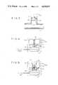
- FIG. 3is an embodiment of a diaphragm pressure sensor
- FIG. 4is an embodiment of an air-pressure actuable switch, being a pressure ON, no pressure OFF switch;
- FIG. 5is an embodiment of an air-pressure actuable switch, being a latching switch.
- the pump protection system shown in FIG. 1, for a domestic whirlpool bath,is for protecting a pump driven by an electric motor (not shown) which is connected to the usual line and neutral power supply lines 10 and 11 and to an earth 12.
- Switch S2is a simple ON-OFF switch being ON when the actuating air-pressure signal is present (positive) and OFF when there is no such signal.
- Switch S1ain contrast is a latching switch which first sets to ON when an air-pressure signal is received by the switch and then remains ON when the signal is no longer there, the switch only changing to OFF when a further positive air-pressure signal is received.
- Switches S1b and S2are not of exactly the same type, though they are similar: S2 is a pressure switch designed, due to the choice of spring internally, to switch at a range of pressures which is adjustable using a fine adjustment screw; S1b is simply a switch with no adjustability.
- the air-pressure signals for actuating the switches S2, S1a and S1bare generated by two devices, namely a diaphragm pressure sensor 14 and a diaphragm push-button 15. Instead of diaphragm devices, bellows devices could be used.
- the sensor 14is, when installed, located in the outlet pipe leading from the pump so that in operation it senses the dynamic pressure of water created by the pump at its outlet.
- the increased pressure in the water during pumping operationcauses the diaphragm or bellows to deflect and generate an air pressure signal which is fed via an air signal line 17 to the switch S2 to actuate that switch to close it (ON).
- the push-button 15is a manually operable device. When the button is pressed it deflects a diaphragm or bellows to send air signals via two air signal lines 18 and 19 to the switches S1a and S1b. From the push-button 15 there is a single air line, labelled 18/19, which divides at a tee-piece 16 in the "control box" to the individual lines 18 and 19, as close to the switches S1a and S1b as possible to minimise the volume of air between those switches and the push-button 15.
- Switches S1a and S1bdo not need to be adjustable.
- the push-button 15is pressed until sufficient air pressure is developed to trip those switches. When the button 15 is released those air-pressure signals cease.
- the pumpcan now only be restarted (once the blockage has been removed or the bath re-filled) by pressing the push-button 15 twice, once to re-set the latching switch to OFF and again to close both switches S1a and S1b to energise the pump motor.
- the advantage of using a latching switch that has to be manually re-set by the push-button 15is that with the pump operating normally, when the user wants to switch if off, e.g. to empty the bath, he simply presses the push-button 15 which causes the latching switch S1a to open.
- the sensor 14is designed to operate at a pressure of around 1 or 2 p.s.i. This may be adjustable, either at the sensor 14 and/or at the switch S2.
- the operating air pressure of the push-button device 15 and/or of the switches S1a and S1bmay but need not normally be adjustable.
- the sensor 14 and push-button device 15are both non-electrical and are connected to the electrical switches S1a, S1b and S2 only by the air signal lines 17,18,19 so that their operation is quite safe even though they are operated in wet conditions.
- the electrical supply lines 10 to 12 and the motor itselfmay be located at a remote, safe distance from the bath interior.
- a carefully sized bleed hole(not shown) may be provided in the line 18/19 or line 19 which has the effect of limiting the time for which the switch S1b will remain closed. The time is limited according to the diameter of the bleed hole and might typically be 3 seconds for a bleed hole diameter of 0.3 mm.
- the bleed holemay conveniently be drilled in the tee-piece 16; or it may be a calibrated orifice built in to the tee-piece or at some other location.
- the bleed holemust be of sufficiently small diameter to avoid too much loss of air from the system whilst switching is actually taking place.
- FIG. 2works in principle in a similar way to that shown in FIG. 1 and where appropriate the same references have been used.
- switches S1a, S1b and S2instead of acting directly in the power supply line 10 are connected between line 10 and neutral 11 so that by including suitable current limiters (not shown) they do not carry the full supply current. Rather, the switches control relays RLA 1 and RLA 2, the switch contacts of which are connected in the line 10.
- the push-button 15To re-start the pump when normal operating conditions are restored, the push-button 15 must be pressed twice; the first time will un-latch switch S1a and the second pressing closes both switches S1a and S1b as before.
- the push-button 15is simply pressed once to unlatch switch S1a and open relay switch contacts RLA 1.
- a safeguard to prevent prolonged operation of the motor with the bath empty by holding down the button 15,may be provided by means of a bleed hole in the line 19 as decribed above for FIG. 1.
- the diaphragm pressure sensor 14 shown in FIG. 3is located in a branch 20 of the pump outlet duct 21 leading from the pump to a nozzle or nozzles in the whirlpool bath wall.
- a small plastics collar 22is cemented in the end of the branch 20 to hold the sensor 14 in place. Water pressure in the duct 21 and branch 20 acts to deflect the diaphragm 25 and cause a small air pressure signal to pass along the signal line 17.
- the air-pressure responsive switch shown in FIG. 4has a receiving chamber 27 to which an air pressure signal is fed by the signal line 17 or 19, a wall of the chamber 27 being a diaphragm 28 which deflects upwardly to pivot a rocker 30 which depresses the button 31 of a microswitch 32.
- a return spring 35ensures that the diaphragm 28 relaxes and that the button 31 can move to its OFF position when the air signal in line 17 or 19 is no longer present.
- An adjusting screw 37can be used to set the air pressure at which the air signal actuates the switch.
- the air-pressure responsive latching switch shown in FIG. 5is generally similar to the ON-OFF switch shown in FIG. 4, the difference being that deflection of the diaphragm 28 causes movement of a latch even when the diaphragm 28 relaxes.
- the diaphragm 28deflects a second time it raises both the latch member 40 and the latch release member 41 to unlatch member 40 and allow it to fall when the diaphragm again relaxes, causing the microswitch to be switched off.
- the pressure diaphragm 14is intended to be used in the pump outlet. If a pressure sensor is to be used in the pump inlet it would need to respond only at a pre-determined suction pressure but not if the pressure falls below that value or rises to zero. Possibly two pressure transducers would be needed to achieve this.
- the pump protection systemcould also be used with pump assisted shower units. Such pumps are necessary when the header tank is located at too low a level to give a sufficient head for showering. They are usually installed on the down-stream side of the shower valve. However, if the pump system pumps, simultaneously, hot and cold feds to the shower mixer valve, the protection of the pump system might have to be based on the alternative system which senses a change in pressure on the suction line, since otherwise a system sensing pressure at the pump outlet might not switch off the pump if only one of the supplies became blocked and damage to that side of the dual impeller pump could ensue.
Landscapes
- Engineering & Computer Science (AREA)
- Mechanical Engineering (AREA)
- General Engineering & Computer Science (AREA)
- Control Of Non-Positive-Displacement Pumps (AREA)
- Percussion Or Vibration Massage (AREA)
Abstract
Description
Claims (15)
Applications Claiming Priority (2)
| Application Number | Priority Date | Filing Date | Title |
|---|---|---|---|
| GB8315154 | 1983-06-02 | ||
| GB838315154AGB8315154D0 (en) | 1983-06-02 | 1983-06-02 | Pump protection system |
Publications (1)
| Publication Number | Publication Date |
|---|---|
| US4620835Atrue US4620835A (en) | 1986-11-04 |
Family
ID=10543695
Family Applications (1)
| Application Number | Title | Priority Date | Filing Date |
|---|---|---|---|
| US06/616,110Expired - LifetimeUS4620835A (en) | 1983-06-02 | 1984-06-01 | Pump protection system |
Country Status (4)
| Country | Link |
|---|---|
| US (1) | US4620835A (en) |
| EP (1) | EP0131368B1 (en) |
| DE (1) | DE3468258D1 (en) |
| GB (1) | GB8315154D0 (en) |
Cited By (55)
| Publication number | Priority date | Publication date | Assignee | Title |
|---|---|---|---|---|
| US4861231A (en)* | 1988-11-10 | 1989-08-29 | Howard Herbert H | Liquid level sensing device |
| US5167041A (en)* | 1990-06-20 | 1992-12-01 | Kdi American Products, Inc. | Suction fitting with pump control device |
| US5347664A (en)* | 1990-06-20 | 1994-09-20 | Kdi American Products, Inc. | Suction fitting with pump control device |
| US5570481A (en)* | 1994-11-09 | 1996-11-05 | Vico Products Manufacturing Co., Inc. | Suction-actuated control system for whirlpool bath/spa installations |
| US5681025A (en)* | 1995-01-20 | 1997-10-28 | Kohler Co. | Motor operated butterfly valve with a multi-function seal |
| US5690476A (en)* | 1996-10-25 | 1997-11-25 | Miller; Bernard J. | Safety device for avoiding entrapment at a water reservoir drain |
| US5725359A (en)* | 1996-10-16 | 1998-03-10 | B&S Plastics, Inc. | Pool pump controller |
| US5822807A (en)* | 1997-03-24 | 1998-10-20 | Gallagher; Patrick J. | Suction relief apparatus |
| US5865601A (en)* | 1998-02-06 | 1999-02-02 | Miller; Bernard J. | Safety device for avoiding entrapment at a water reservoir drain having a secondary blowing pump |
| US5947700A (en)* | 1997-07-28 | 1999-09-07 | Mckain; Paul C. | Fluid vacuum safety device for fluid transfer systems in swimming pools |
| US6059536A (en)* | 1996-01-22 | 2000-05-09 | O.I.A. Llc | Emergency shutdown system for a water-circulating pump |
| US6253391B1 (en)* | 1999-09-06 | 2001-07-03 | Nichigi Engineering Co., Ltd. | Safety system at a discharge port in a pool |
| US6269493B2 (en) | 1999-10-12 | 2001-08-07 | Edwin C. Sorensen | Breakaway drain cover |
| EP1120259A3 (en)* | 2000-01-21 | 2001-12-12 | Seiko Epson Corporation | Ink-jet recording apparatus |
| US6342841B1 (en) | 1998-04-10 | 2002-01-29 | O.I.A. Llc | Influent blockage detection system |
| US20030221674A1 (en)* | 2002-05-31 | 2003-12-04 | Scanderbeg Berardino C. | System and method for monitoring aircraft fuel pump conditions for automated shutdown |
| US20040213676A1 (en)* | 2003-04-25 | 2004-10-28 | Phillips David L. | Active sensing and switching device |
| US20050226731A1 (en)* | 2004-04-09 | 2005-10-13 | A.O. Smith Corporation | Controller for a motor and a method of controlling the motor |
| US20060090255A1 (en)* | 2004-11-01 | 2006-05-04 | Fail-Safe Llc | Load Sensor Safety Vacuum Release System |
| US20060127227A1 (en)* | 2004-04-09 | 2006-06-15 | A.O. Smith Corporation | Controller for a motor and a method of controlling the motor |
| US20080010983A1 (en)* | 2006-07-13 | 2008-01-17 | Emerson Electric Co. | Low suction vacuum detector |
| US20080095640A1 (en)* | 2006-10-13 | 2008-04-24 | A.O. Smith Corporation | Controller for a motor and a method of controlling the motor |
| EP1975416A3 (en)* | 2007-03-24 | 2009-08-26 | DLP Limited | Shower flow simulator |
| US20090290990A1 (en)* | 2006-10-13 | 2009-11-26 | Brian Thomas Branecky | Controller for a motor and a method of controlling the motor |
| US20100080714A1 (en)* | 2008-10-01 | 2010-04-01 | A. O. Smith Corporation | Controller for a motor and a method of controlling the motor |
| US20100180811A1 (en)* | 2009-01-21 | 2010-07-22 | George Sotiriou | Water level detector |
| US7857600B2 (en) | 2003-12-08 | 2010-12-28 | Sta-Rite Industries, Llc | Pump controller system and method |
| US20110079025A1 (en)* | 2009-10-02 | 2011-04-07 | Thermo King Corporation | Thermal storage device with ice thickness detection and control methods |
| US7931447B2 (en) | 2006-06-29 | 2011-04-26 | Hayward Industries, Inc. | Drain safety and pump control device |
| US7988425B1 (en) | 2006-06-06 | 2011-08-02 | Stingl David A | Pump and alarm control |
| US20110286859A1 (en)* | 2006-06-29 | 2011-11-24 | Gary Ortiz | Pump Controller With External Device Control Capability |
| US8436559B2 (en) | 2009-06-09 | 2013-05-07 | Sta-Rite Industries, Llc | System and method for motor drive control pad and drive terminals |
| US8459195B2 (en) | 2011-04-28 | 2013-06-11 | Michael H. IRVING | Self load sensing circuit board controller diaphragm pump |
| US8465262B2 (en) | 2004-08-26 | 2013-06-18 | Pentair Water Pool And Spa, Inc. | Speed control |
| US8469675B2 (en) | 2004-08-26 | 2013-06-25 | Pentair Water Pool And Spa, Inc. | Priming protection |
| US20130167938A1 (en)* | 2010-09-24 | 2013-07-04 | Dlp Limited | Remote monitoring shower water apparatus and method of remote monitoring a showering user |
| US8480373B2 (en) | 2004-08-26 | 2013-07-09 | Pentair Water Pool And Spa, Inc. | Filter loading |
| US8500413B2 (en) | 2004-08-26 | 2013-08-06 | Pentair Water Pool And Spa, Inc. | Pumping system with power optimization |
| US8564233B2 (en) | 2009-06-09 | 2013-10-22 | Sta-Rite Industries, Llc | Safety system and method for pump and motor |
| US8573951B1 (en) | 2009-10-02 | 2013-11-05 | Play-It-Safe Technologies, LLC | Pool recirculation pump safety system and method |
| US8602745B2 (en) | 2004-08-26 | 2013-12-10 | Pentair Water Pool And Spa, Inc. | Anti-entrapment and anti-dead head function |
| US8602743B2 (en) | 2008-10-06 | 2013-12-10 | Pentair Water Pool And Spa, Inc. | Method of operating a safety vacuum release system |
| US8801389B2 (en) | 2004-08-26 | 2014-08-12 | Pentair Water Pool And Spa, Inc. | Flow control |
| US9404500B2 (en) | 2004-08-26 | 2016-08-02 | Pentair Water Pool And Spa, Inc. | Control algorithm of variable speed pumping system |
| US9556874B2 (en) | 2009-06-09 | 2017-01-31 | Pentair Flow Technologies, Llc | Method of controlling a pump and motor |
| US9568005B2 (en) | 2010-12-08 | 2017-02-14 | Pentair Water Pool And Spa, Inc. | Discharge vacuum relief valve for safety vacuum release system |
| US20170213451A1 (en) | 2016-01-22 | 2017-07-27 | Hayward Industries, Inc. | Systems and Methods for Providing Network Connectivity and Remote Monitoring, Optimization, and Control of Pool/Spa Equipment |
| US9885360B2 (en) | 2012-10-25 | 2018-02-06 | Pentair Flow Technologies, Llc | Battery backup sump pump systems and methods |
| US10030647B2 (en) | 2010-02-25 | 2018-07-24 | Hayward Industries, Inc. | Universal mount for a variable speed pump drive user interface |
| US10465676B2 (en) | 2011-11-01 | 2019-11-05 | Pentair Water Pool And Spa, Inc. | Flow locking system and method |
| US10718337B2 (en) | 2016-09-22 | 2020-07-21 | Hayward Industries, Inc. | Self-priming dedicated water feature pump |
| US20200319621A1 (en) | 2016-01-22 | 2020-10-08 | Hayward Industries, Inc. | Systems and Methods for Providing Network Connectivity and Remote Monitoring, Optimization, and Control of Pool/Spa Equipment |
| US10947981B2 (en) | 2004-08-26 | 2021-03-16 | Pentair Water Pool And Spa, Inc. | Variable speed pumping system and method |
| US10976713B2 (en) | 2013-03-15 | 2021-04-13 | Hayward Industries, Inc. | Modular pool/spa control system |
| US20210270259A1 (en)* | 2020-03-02 | 2021-09-02 | Fna Group, Inc. | Fluid sensing safety |
Families Citing this family (3)
| Publication number | Priority date | Publication date | Assignee | Title |
|---|---|---|---|---|
| US4969801A (en)* | 1989-11-06 | 1990-11-13 | Ingersoll-Rand Company | Method and apparatus for shutting off a compressor when it rotates in reverse direction |
| CA2101170A1 (en)* | 1991-01-22 | 1992-07-23 | Geoffrey R. Percival | Safety device |
| US12232445B2 (en)* | 2019-02-11 | 2025-02-25 | Agco Corporation | Harvesting header having a hydraulic fluid loop and related systems and methods |
Citations (17)
| Publication number | Priority date | Publication date | Assignee | Title |
|---|---|---|---|---|
| US2765743A (en)* | 1952-07-18 | 1956-10-09 | Control Mfg Company | Pump control |
| US2933570A (en)* | 1958-01-06 | 1960-04-19 | Kenco Pump Division Of The Ame | Pressure sensitive pump control |
| US3292547A (en)* | 1965-11-02 | 1966-12-20 | Ernest A Ward | Pressure-actuated pump control mechanisms |
| DE1560635A1 (en)* | 1963-09-27 | 1970-03-12 | Zellweger Ag App U Maschinenfa | Device for monitoring the operation of winding machines and other yarn processing machines |
| DE1810907A1 (en)* | 1968-11-26 | 1970-06-04 | Spuhr & Co M | Safety pressure switch |
| DE1573660A1 (en)* | 1966-04-15 | 1970-08-13 | Licentia Gmbh | Circuit arrangement for the delayed activation of a lint monitor |
| DE1906609A1 (en)* | 1969-02-11 | 1970-08-20 | Otto Tuchenhagen | Procedure for the pump protection of a milk receiving station |
| US3679325A (en)* | 1970-09-16 | 1972-07-25 | Clyde E Yost | Automatic pump control |
| US3702742A (en)* | 1968-03-29 | 1972-11-14 | Itt | Water pressure and like systems |
| US3716306A (en)* | 1971-03-31 | 1973-02-13 | Micropump Corp | Gear pump construction |
| DE2533754A1 (en)* | 1974-07-29 | 1976-02-12 | Owens Corning Fiberglass Corp | METHOD AND DEVICE FOR PROCESSING STRENGTHS |
| US3999890A (en)* | 1974-04-12 | 1976-12-28 | Niedermeyer Karl O | Enclosed sump pump |
| US4070133A (en)* | 1976-02-09 | 1978-01-24 | Mccormick Homer | Pump compressor unit for use with pumping draft beer |
| AT343746B (en)* | 1972-10-14 | 1978-06-12 | Huba Control Ag | ACTUATOR BUTTON FOR A SWITCH ACTUATED BY MEANS OF FLUID PRESSURE |
| US4115878A (en)* | 1977-03-14 | 1978-09-26 | South Pacific Industries | Spa safety drain |
| US4233694A (en)* | 1979-01-22 | 1980-11-18 | Jacuzzi Whirlpool Bath, Inc. | Spa construction and isolated controls therefor |
| US4476889A (en)* | 1981-04-07 | 1984-10-16 | Haynes Henry T | Control valve and switch assembly |
- 1983
- 1983-06-02GBGB838315154Apatent/GB8315154D0/enactivePending
- 1984
- 1984-06-01DEDE8484303681Tpatent/DE3468258D1/ennot_activeExpired
- 1984-06-01USUS06/616,110patent/US4620835A/ennot_activeExpired - Lifetime
- 1984-06-01EPEP84303681Apatent/EP0131368B1/ennot_activeExpired
Patent Citations (18)
| Publication number | Priority date | Publication date | Assignee | Title |
|---|---|---|---|---|
| US2765743A (en)* | 1952-07-18 | 1956-10-09 | Control Mfg Company | Pump control |
| US2933570A (en)* | 1958-01-06 | 1960-04-19 | Kenco Pump Division Of The Ame | Pressure sensitive pump control |
| DE1560635A1 (en)* | 1963-09-27 | 1970-03-12 | Zellweger Ag App U Maschinenfa | Device for monitoring the operation of winding machines and other yarn processing machines |
| US3292547A (en)* | 1965-11-02 | 1966-12-20 | Ernest A Ward | Pressure-actuated pump control mechanisms |
| DE1573660A1 (en)* | 1966-04-15 | 1970-08-13 | Licentia Gmbh | Circuit arrangement for the delayed activation of a lint monitor |
| US3702742A (en)* | 1968-03-29 | 1972-11-14 | Itt | Water pressure and like systems |
| DE1810907A1 (en)* | 1968-11-26 | 1970-06-04 | Spuhr & Co M | Safety pressure switch |
| DE1906609A1 (en)* | 1969-02-11 | 1970-08-20 | Otto Tuchenhagen | Procedure for the pump protection of a milk receiving station |
| US3679325A (en)* | 1970-09-16 | 1972-07-25 | Clyde E Yost | Automatic pump control |
| US3716306A (en)* | 1971-03-31 | 1973-02-13 | Micropump Corp | Gear pump construction |
| AT343746B (en)* | 1972-10-14 | 1978-06-12 | Huba Control Ag | ACTUATOR BUTTON FOR A SWITCH ACTUATED BY MEANS OF FLUID PRESSURE |
| US3999890A (en)* | 1974-04-12 | 1976-12-28 | Niedermeyer Karl O | Enclosed sump pump |
| DE2533754A1 (en)* | 1974-07-29 | 1976-02-12 | Owens Corning Fiberglass Corp | METHOD AND DEVICE FOR PROCESSING STRENGTHS |
| GB1516356A (en)* | 1974-07-29 | 1978-07-05 | Owens Corning Fiberglass Corp | Method for controlling the advancement of linear elements |
| US4070133A (en)* | 1976-02-09 | 1978-01-24 | Mccormick Homer | Pump compressor unit for use with pumping draft beer |
| US4115878A (en)* | 1977-03-14 | 1978-09-26 | South Pacific Industries | Spa safety drain |
| US4233694A (en)* | 1979-01-22 | 1980-11-18 | Jacuzzi Whirlpool Bath, Inc. | Spa construction and isolated controls therefor |
| US4476889A (en)* | 1981-04-07 | 1984-10-16 | Haynes Henry T | Control valve and switch assembly |
Cited By (123)
| Publication number | Priority date | Publication date | Assignee | Title |
|---|---|---|---|---|
| US4861231A (en)* | 1988-11-10 | 1989-08-29 | Howard Herbert H | Liquid level sensing device |
| US5167041A (en)* | 1990-06-20 | 1992-12-01 | Kdi American Products, Inc. | Suction fitting with pump control device |
| US5347664A (en)* | 1990-06-20 | 1994-09-20 | Kdi American Products, Inc. | Suction fitting with pump control device |
| US5570481A (en)* | 1994-11-09 | 1996-11-05 | Vico Products Manufacturing Co., Inc. | Suction-actuated control system for whirlpool bath/spa installations |
| US5681025A (en)* | 1995-01-20 | 1997-10-28 | Kohler Co. | Motor operated butterfly valve with a multi-function seal |
| US6059536A (en)* | 1996-01-22 | 2000-05-09 | O.I.A. Llc | Emergency shutdown system for a water-circulating pump |
| US5725359A (en)* | 1996-10-16 | 1998-03-10 | B&S Plastics, Inc. | Pool pump controller |
| US5690476A (en)* | 1996-10-25 | 1997-11-25 | Miller; Bernard J. | Safety device for avoiding entrapment at a water reservoir drain |
| US5822807A (en)* | 1997-03-24 | 1998-10-20 | Gallagher; Patrick J. | Suction relief apparatus |
| US5947700A (en)* | 1997-07-28 | 1999-09-07 | Mckain; Paul C. | Fluid vacuum safety device for fluid transfer systems in swimming pools |
| US5865601A (en)* | 1998-02-06 | 1999-02-02 | Miller; Bernard J. | Safety device for avoiding entrapment at a water reservoir drain having a secondary blowing pump |
| US6342841B1 (en) | 1998-04-10 | 2002-01-29 | O.I.A. Llc | Influent blockage detection system |
| US6253391B1 (en)* | 1999-09-06 | 2001-07-03 | Nichigi Engineering Co., Ltd. | Safety system at a discharge port in a pool |
| US6269493B2 (en) | 1999-10-12 | 2001-08-07 | Edwin C. Sorensen | Breakaway drain cover |
| US7048363B2 (en) | 2000-01-21 | 2006-05-23 | Seiko Epson Corporation | Ink-jet recording apparatus |
| EP1120259A3 (en)* | 2000-01-21 | 2001-12-12 | Seiko Epson Corporation | Ink-jet recording apparatus |
| US6733114B2 (en) | 2000-01-21 | 2004-05-11 | Seiko Epson Corporation | Ink-jet recording apparatus |
| US20040174417A1 (en)* | 2000-01-21 | 2004-09-09 | Seiko Epson Corporation | Ink-jet recording apparatus |
| US20040196339A1 (en)* | 2000-01-21 | 2004-10-07 | Seiko Epson Corporation | Ink-jet recording apparatus |
| EP1754608A3 (en)* | 2000-01-21 | 2007-04-11 | Seiko Epson Corporation | Ink-jet recording apparatus |
| EP1747888A3 (en)* | 2000-01-21 | 2007-04-11 | Seiko Epson Corporation | Ink-jet recording apparatus |
| US6913350B2 (en) | 2000-01-21 | 2005-07-05 | Seiko Epson Corporation | Ink-jet recording apparatus |
| US20050214127A1 (en)* | 2002-05-31 | 2005-09-29 | Scanderbeg Berardino C | Fuel pump with automatic shutoff |
| US6908289B2 (en)* | 2002-05-31 | 2005-06-21 | Hydro-Aire, Inc. | Fuel pump with automatic shutoff |
| US7393185B2 (en) | 2002-05-31 | 2008-07-01 | Hydro-Aire, Inc. | Fuel pump with automatic shutoff |
| US20030221674A1 (en)* | 2002-05-31 | 2003-12-04 | Scanderbeg Berardino C. | System and method for monitoring aircraft fuel pump conditions for automated shutdown |
| US6998807B2 (en) | 2003-04-25 | 2006-02-14 | Itt Manufacturing Enterprises, Inc. | Active sensing and switching device |
| US20040213676A1 (en)* | 2003-04-25 | 2004-10-28 | Phillips David L. | Active sensing and switching device |
| US9371829B2 (en) | 2003-12-08 | 2016-06-21 | Pentair Water Pool And Spa, Inc. | Pump controller system and method |
| US8444394B2 (en) | 2003-12-08 | 2013-05-21 | Sta-Rite Industries, Llc | Pump controller system and method |
| US10416690B2 (en) | 2003-12-08 | 2019-09-17 | Pentair Water Pool And Spa, Inc. | Pump controller system and method |
| US9399992B2 (en) | 2003-12-08 | 2016-07-26 | Pentair Water Pool And Spa, Inc. | Pump controller system and method |
| US10241524B2 (en) | 2003-12-08 | 2019-03-26 | Pentair Water Pool And Spa, Inc. | Pump controller system and method |
| US10642287B2 (en) | 2003-12-08 | 2020-05-05 | Pentair Water Pool And Spa, Inc. | Pump controller system and method |
| US9328727B2 (en) | 2003-12-08 | 2016-05-03 | Pentair Water Pool And Spa, Inc. | Pump controller system and method |
| US7857600B2 (en) | 2003-12-08 | 2010-12-28 | Sta-Rite Industries, Llc | Pump controller system and method |
| US10289129B2 (en) | 2003-12-08 | 2019-05-14 | Pentair Water Pool And Spa, Inc. | Pump controller system and method |
| US8540493B2 (en) | 2003-12-08 | 2013-09-24 | Sta-Rite Industries, Llc | Pump control system and method |
| US10409299B2 (en) | 2003-12-08 | 2019-09-10 | Pentair Water Pool And Spa, Inc. | Pump controller system and method |
| US20100068073A1 (en)* | 2004-04-09 | 2010-03-18 | A. O. Smith Corporation | Controller for a motor and a method of controlling the motor |
| US20050226731A1 (en)* | 2004-04-09 | 2005-10-13 | A.O. Smith Corporation | Controller for a motor and a method of controlling the motor |
| US20060127227A1 (en)* | 2004-04-09 | 2006-06-15 | A.O. Smith Corporation | Controller for a motor and a method of controlling the motor |
| US8177520B2 (en)* | 2004-04-09 | 2012-05-15 | Regal Beloit Epc Inc. | Controller for a motor and a method of controlling the motor |
| US8353678B2 (en) | 2004-04-09 | 2013-01-15 | Regal Beloit Epc Inc. | Controller for a motor and a method of controlling the motor |
| US8133034B2 (en)* | 2004-04-09 | 2012-03-13 | Regal Beloit Epc Inc. | Controller for a motor and a method of controlling the motor |
| US8282361B2 (en) | 2004-04-09 | 2012-10-09 | Regal Beloit Epc Inc. | Controller for a motor and a method of controlling the motor |
| US10871001B2 (en) | 2004-08-26 | 2020-12-22 | Pentair Water Pool And Spa, Inc. | Filter loading |
| US10871163B2 (en) | 2004-08-26 | 2020-12-22 | Pentair Water Pool And Spa, Inc. | Pumping system and method having an independent controller |
| US10527042B2 (en) | 2004-08-26 | 2020-01-07 | Pentair Water Pool And Spa, Inc. | Speed control |
| US9605680B2 (en) | 2004-08-26 | 2017-03-28 | Pentair Water Pool And Spa, Inc. | Control algorithm of variable speed pumping system |
| US10502203B2 (en) | 2004-08-26 | 2019-12-10 | Pentair Water Pool And Spa, Inc. | Speed control |
| US10480516B2 (en) | 2004-08-26 | 2019-11-19 | Pentair Water Pool And Spa, Inc. | Anti-entrapment and anti-deadhead function |
| US9932984B2 (en) | 2004-08-26 | 2018-04-03 | Pentair Water Pool And Spa, Inc. | Pumping system with power optimization |
| US9551344B2 (en) | 2004-08-26 | 2017-01-24 | Pentair Water Pool And Spa, Inc. | Anti-entrapment and anti-dead head function |
| US10415569B2 (en) | 2004-08-26 | 2019-09-17 | Pentair Water Pool And Spa, Inc. | Flow control |
| US8465262B2 (en) | 2004-08-26 | 2013-06-18 | Pentair Water Pool And Spa, Inc. | Speed control |
| US8469675B2 (en) | 2004-08-26 | 2013-06-25 | Pentair Water Pool And Spa, Inc. | Priming protection |
| US10731655B2 (en) | 2004-08-26 | 2020-08-04 | Pentair Water Pool And Spa, Inc. | Priming protection |
| US8480373B2 (en) | 2004-08-26 | 2013-07-09 | Pentair Water Pool And Spa, Inc. | Filter loading |
| US8500413B2 (en) | 2004-08-26 | 2013-08-06 | Pentair Water Pool And Spa, Inc. | Pumping system with power optimization |
| US9777733B2 (en) | 2004-08-26 | 2017-10-03 | Pentair Water Pool And Spa, Inc. | Flow control |
| US9404500B2 (en) | 2004-08-26 | 2016-08-02 | Pentair Water Pool And Spa, Inc. | Control algorithm of variable speed pumping system |
| US10240606B2 (en)* | 2004-08-26 | 2019-03-26 | Pentair Water Pool And Spa, Inc. | Pumping system with two way communication |
| US8573952B2 (en) | 2004-08-26 | 2013-11-05 | Pentair Water Pool And Spa, Inc. | Priming protection |
| US8602745B2 (en) | 2004-08-26 | 2013-12-10 | Pentair Water Pool And Spa, Inc. | Anti-entrapment and anti-dead head function |
| US10240604B2 (en) | 2004-08-26 | 2019-03-26 | Pentair Water Pool And Spa, Inc. | Pumping system with housing and user interface |
| US8801389B2 (en) | 2004-08-26 | 2014-08-12 | Pentair Water Pool And Spa, Inc. | Flow control |
| US8840376B2 (en) | 2004-08-26 | 2014-09-23 | Pentair Water Pool And Spa, Inc. | Pumping system with power optimization |
| US20150030463A1 (en)* | 2004-08-26 | 2015-01-29 | Robert W. Stiles, Jr. | Pumping System with Two Way Communication |
| US9051930B2 (en) | 2004-08-26 | 2015-06-09 | Pentair Water Pool And Spa, Inc. | Speed control |
| US10947981B2 (en) | 2004-08-26 | 2021-03-16 | Pentair Water Pool And Spa, Inc. | Variable speed pumping system and method |
| US11073155B2 (en) | 2004-08-26 | 2021-07-27 | Pentair Water Pool And Spa, Inc. | Pumping system with power optimization |
| US11391281B2 (en) | 2004-08-26 | 2022-07-19 | Pentair Water Pool And Spa, Inc. | Priming protection |
| US8281425B2 (en)* | 2004-11-01 | 2012-10-09 | Cohen Joseph D | Load sensor safety vacuum release system |
| US20060090255A1 (en)* | 2004-11-01 | 2006-05-04 | Fail-Safe Llc | Load Sensor Safety Vacuum Release System |
| US7988425B1 (en) | 2006-06-06 | 2011-08-02 | Stingl David A | Pump and alarm control |
| US7931447B2 (en) | 2006-06-29 | 2011-04-26 | Hayward Industries, Inc. | Drain safety and pump control device |
| US20110286859A1 (en)* | 2006-06-29 | 2011-11-24 | Gary Ortiz | Pump Controller With External Device Control Capability |
| US20080010983A1 (en)* | 2006-07-13 | 2008-01-17 | Emerson Electric Co. | Low suction vacuum detector |
| US8360736B2 (en) | 2006-10-13 | 2013-01-29 | Regal Beloit Epc Inc. | Controller for a motor and a method of controlling the motor |
| US8177519B2 (en) | 2006-10-13 | 2012-05-15 | Regal Beloit Epc Inc. | Controller for a motor and a method of controlling the motor |
| US20090290990A1 (en)* | 2006-10-13 | 2009-11-26 | Brian Thomas Branecky | Controller for a motor and a method of controlling the motor |
| US7690897B2 (en) | 2006-10-13 | 2010-04-06 | A.O. Smith Corporation | Controller for a motor and a method of controlling the motor |
| US20080095640A1 (en)* | 2006-10-13 | 2008-04-24 | A.O. Smith Corporation | Controller for a motor and a method of controlling the motor |
| EP1975416A3 (en)* | 2007-03-24 | 2009-08-26 | DLP Limited | Shower flow simulator |
| US8354809B2 (en) | 2008-10-01 | 2013-01-15 | Regal Beloit Epc Inc. | Controller for a motor and a method of controlling the motor |
| US20100080714A1 (en)* | 2008-10-01 | 2010-04-01 | A. O. Smith Corporation | Controller for a motor and a method of controlling the motor |
| US8602743B2 (en) | 2008-10-06 | 2013-12-10 | Pentair Water Pool And Spa, Inc. | Method of operating a safety vacuum release system |
| US10724263B2 (en) | 2008-10-06 | 2020-07-28 | Pentair Water Pool And Spa, Inc. | Safety vacuum release system |
| US9726184B2 (en) | 2008-10-06 | 2017-08-08 | Pentair Water Pool And Spa, Inc. | Safety vacuum release system |
| US20100180811A1 (en)* | 2009-01-21 | 2010-07-22 | George Sotiriou | Water level detector |
| US8564233B2 (en) | 2009-06-09 | 2013-10-22 | Sta-Rite Industries, Llc | Safety system and method for pump and motor |
| US11493034B2 (en) | 2009-06-09 | 2022-11-08 | Pentair Flow Technologies, Llc | Method of controlling a pump and motor |
| US9556874B2 (en) | 2009-06-09 | 2017-01-31 | Pentair Flow Technologies, Llc | Method of controlling a pump and motor |
| US10590926B2 (en) | 2009-06-09 | 2020-03-17 | Pentair Flow Technologies, Llc | Method of controlling a pump and motor |
| US8436559B2 (en) | 2009-06-09 | 2013-05-07 | Sta-Rite Industries, Llc | System and method for motor drive control pad and drive terminals |
| US9712098B2 (en) | 2009-06-09 | 2017-07-18 | Pentair Flow Technologies, Llc | Safety system and method for pump and motor |
| US20110079025A1 (en)* | 2009-10-02 | 2011-04-07 | Thermo King Corporation | Thermal storage device with ice thickness detection and control methods |
| US8573951B1 (en) | 2009-10-02 | 2013-11-05 | Play-It-Safe Technologies, LLC | Pool recirculation pump safety system and method |
| US11572877B2 (en) | 2010-02-25 | 2023-02-07 | Hayward Industries, Inc. | Universal mount for a variable speed pump drive user interface |
| US12018677B2 (en) | 2010-02-25 | 2024-06-25 | Hayward Industries, Inc. | Universal mount for a variable speed pump drive user interface |
| US10030647B2 (en) | 2010-02-25 | 2018-07-24 | Hayward Industries, Inc. | Universal mount for a variable speed pump drive user interface |
| US20130167938A1 (en)* | 2010-09-24 | 2013-07-04 | Dlp Limited | Remote monitoring shower water apparatus and method of remote monitoring a showering user |
| US9568005B2 (en) | 2010-12-08 | 2017-02-14 | Pentair Water Pool And Spa, Inc. | Discharge vacuum relief valve for safety vacuum release system |
| US8459195B2 (en) | 2011-04-28 | 2013-06-11 | Michael H. IRVING | Self load sensing circuit board controller diaphragm pump |
| US10465676B2 (en) | 2011-11-01 | 2019-11-05 | Pentair Water Pool And Spa, Inc. | Flow locking system and method |
| US10883489B2 (en) | 2011-11-01 | 2021-01-05 | Pentair Water Pool And Spa, Inc. | Flow locking system and method |
| US9885360B2 (en) | 2012-10-25 | 2018-02-06 | Pentair Flow Technologies, Llc | Battery backup sump pump systems and methods |
| US11822300B2 (en) | 2013-03-15 | 2023-11-21 | Hayward Industries, Inc. | Modular pool/spa control system |
| US10976713B2 (en) | 2013-03-15 | 2021-04-13 | Hayward Industries, Inc. | Modular pool/spa control system |
| US11096862B2 (en) | 2016-01-22 | 2021-08-24 | Hayward Industries, Inc. | Systems and methods for providing network connectivity and remote monitoring, optimization, and control of pool/spa equipment |
| US11000449B2 (en) | 2016-01-22 | 2021-05-11 | Hayward Industries, Inc. | Systems and methods for providing network connectivity and remote monitoring, optimization, and control of pool/spa equipment |
| US20170213451A1 (en) | 2016-01-22 | 2017-07-27 | Hayward Industries, Inc. | Systems and Methods for Providing Network Connectivity and Remote Monitoring, Optimization, and Control of Pool/Spa Equipment |
| US11122669B2 (en) | 2016-01-22 | 2021-09-14 | Hayward Industries, Inc. | Systems and methods for providing network connectivity and remote monitoring, optimization, and control of pool/spa equipment |
| US11129256B2 (en) | 2016-01-22 | 2021-09-21 | Hayward Industries, Inc. | Systems and methods for providing network connectivity and remote monitoring, optimization, and control of pool/spa equipment |
| US20200319621A1 (en) | 2016-01-22 | 2020-10-08 | Hayward Industries, Inc. | Systems and Methods for Providing Network Connectivity and Remote Monitoring, Optimization, and Control of Pool/Spa Equipment |
| US10363197B2 (en) | 2016-01-22 | 2019-07-30 | Hayward Industries, Inc. | Systems and methods for providing network connectivity and remote monitoring, optimization, and control of pool/spa equipment |
| US11720085B2 (en) | 2016-01-22 | 2023-08-08 | Hayward Industries, Inc. | Systems and methods for providing network connectivity and remote monitoring, optimization, and control of pool/spa equipment |
| US10272014B2 (en) | 2016-01-22 | 2019-04-30 | Hayward Industries, Inc. | Systems and methods for providing network connectivity and remote monitoring, optimization, and control of pool/spa equipment |
| US10219975B2 (en) | 2016-01-22 | 2019-03-05 | Hayward Industries, Inc. | Systems and methods for providing network connectivity and remote monitoring, optimization, and control of pool/spa equipment |
| US10718337B2 (en) | 2016-09-22 | 2020-07-21 | Hayward Industries, Inc. | Self-priming dedicated water feature pump |
| US20210270259A1 (en)* | 2020-03-02 | 2021-09-02 | Fna Group, Inc. | Fluid sensing safety |
| US12071943B2 (en)* | 2020-03-02 | 2024-08-27 | Fna Group, Inc. | Fluid sensing safety |
Also Published As
| Publication number | Publication date |
|---|---|
| EP0131368B1 (en) | 1987-12-23 |
| EP0131368A2 (en) | 1985-01-16 |
| EP0131368A3 (en) | 1985-04-10 |
| DE3468258D1 (en) | 1988-02-04 |
| GB8315154D0 (en) | 1983-07-06 |
Similar Documents
| Publication | Publication Date | Title |
|---|---|---|
| US4620835A (en) | Pump protection system | |
| US5495626A (en) | Electrical control device | |
| US5028910A (en) | Drain overflow alarm | |
| US6676831B2 (en) | Modular integrated multifunction pool safety controller (MIMPSC) | |
| EP1585205B1 (en) | Pumping apparatus and method of detecting an entrapment in a pumping apparatus | |
| US6003165A (en) | Portable spa with safety suction shut-off | |
| US2635546A (en) | Pump control | |
| EP0349984A1 (en) | Washing device for parts of human body | |
| US3070021A (en) | Adjustable high turn-on control | |
| EP1250495A1 (en) | Overflow system | |
| US5738495A (en) | Device for contolling the water pressure and flow in a water supply unit | |
| WO2012001683A2 (en) | System for saving the initial water consumption while taking a shower | |
| US4422829A (en) | Sump drain system | |
| WO1992013195A1 (en) | Safety device | |
| EP1178212A2 (en) | Water cooled centrifugal pump | |
| US3656866A (en) | Drain pump control | |
| GB2166645A (en) | Water inflow control in an appliance operable with water | |
| US4800906A (en) | Washing apparatus | |
| US3002064A (en) | Sump pump and flood control equipment | |
| AU605184B2 (en) | Liquid pressure system controller | |
| GB2235490A (en) | Burst pipe prevention | |
| JP2782011B2 (en) | Control method of electric soap dispenser | |
| JP2754882B2 (en) | Steam iron | |
| JP3128711B2 (en) | Bubble tub | |
| GB2186598A (en) | Washing machine comprising an anti-flooding device |
Legal Events
| Date | Code | Title | Description |
|---|---|---|---|
| AS | Assignment | Owner name:AMERICAN STANDARD INC., 40 WEST 40TH ST., NEW YORK Free format text:ASSIGNMENT OF ASSIGNORS INTEREST.;ASSIGNOR:BELL, GERALD A.;REEL/FRAME:004338/0486 Effective date:19840611 Owner name:AMERICAN STANDARD INC.,NEW YORK Free format text:ASSIGNMENT OF ASSIGNORS INTEREST;ASSIGNOR:BELL, GERALD A.;REEL/FRAME:004338/0486 Effective date:19840611 | |
| STCF | Information on status: patent grant | Free format text:PATENTED CASE | |
| AS | Assignment | Owner name:BANKERS TRUST COMPANY Free format text:SECURITY INTEREST;ASSIGNOR:AMERICAN STANDARD INC., A DE. CORP.,;REEL/FRAME:004905/0035 Effective date:19880624 Owner name:BANKERS TRUST COMPANY, 4 ALBANY STREET 9TH FLOOR, Free format text:SECURITY INTEREST;ASSIGNOR:U.S. PLUMBING, INC., A CORPORATION OF DELAWARE;REEL/FRAME:004905/0159 Effective date:19880624 Owner name:BANKERS TRUST COMPANY, NEW YORK Free format text:SECURITY INTEREST;ASSIGNOR:U.S. PLUMBING, INC., A CORPORATION OF DELAWARE;REEL/FRAME:004905/0159 Effective date:19880624 | |
| FEPP | Fee payment procedure | Free format text:PAYOR NUMBER ASSIGNED (ORIGINAL EVENT CODE: ASPN); ENTITY STATUS OF PATENT OWNER: LARGE ENTITY | |
| FPAY | Fee payment | Year of fee payment:4 | |
| AS | Assignment | Owner name:CHEMICAL BANK, AS COLLATERAL AGENT, NEW YORK Free format text:ASSIGNMENT OF ASSIGNORS INTEREST;ASSIGNOR:AMERICAN STANDARD INC.;REEL/FRAME:006566/0170 Effective date:19930601 Owner name:CHEMICAL BANK, AS COLLATERAL AGENT, NEW YORK Free format text:ASSIGNMENT OF SECURITY INTEREST;ASSIGNOR:BANKERS TRUST COMPANY, AS COLLATERAL TRUSTEE;REEL/FRAME:006565/0753 Effective date:19930601 | |
| FEPP | Fee payment procedure | Free format text:PAYER NUMBER DE-ASSIGNED (ORIGINAL EVENT CODE: RMPN); ENTITY STATUS OF PATENT OWNER: LARGE ENTITY Free format text:PAYOR NUMBER ASSIGNED (ORIGINAL EVENT CODE: ASPN); ENTITY STATUS OF PATENT OWNER: LARGE ENTITY | |
| FPAY | Fee payment | Year of fee payment:8 | |
| AS | Assignment | Owner name:AMERICAN STANDARD, INC., NEW JERSEY Free format text:RELEASE OF SECURITY INTEREST (RE-RECORD TO CORRECT DUPLICATES SUBMITTED BY CUSTOMER. THE NEW SCHEDULE CHANGES THE TOTAL NUMBER OF PROPERTY NUMBERS INVOLVED FROM 1133 TO 794. THIS RELEASE OF SECURITY INTEREST WAS PREVIOUSLY RECORDED AT REEL 8869, FRAME 0001.);ASSIGNOR:CHASE MANHATTAN BANK, THE (FORMERLY KNOWN AS CHEMICAL BANK);REEL/FRAME:009123/0300 Effective date:19970801 | |
| AS | Assignment | Owner name:AMERICAN STANDARD, INC., NEW JERSEY Free format text:RELEASE OF SECURITY INTEREST;ASSIGNOR:CHASE MANHATTAN BANK, THE (FORMERLY KNOWN AS CHEMICAL BANK);REEL/FRAME:008869/0001 Effective date:19970801 | |
| FPAY | Fee payment | Year of fee payment:12 |