US4620704A - Universal exercising machine - Google Patents
Universal exercising machineDownload PDFInfo
- Publication number
- US4620704A US4620704AUS06/604,948US60494884AUS4620704AUS 4620704 AUS4620704 AUS 4620704AUS 60494884 AUS60494884 AUS 60494884AUS 4620704 AUS4620704 AUS 4620704A
- Authority
- US
- United States
- Prior art keywords
- base
- exercising machine
- cable
- rods
- universal
- Prior art date
- Legal status (The legal status is an assumption and is not a legal conclusion. Google has not performed a legal analysis and makes no representation as to the accuracy of the status listed.)
- Expired - Lifetime
Links
- 230000033001locomotionEffects0.000claimsabstractdescription5
- 238000003860storageMethods0.000claimsdescription6
- 239000000463materialSubstances0.000claimsdescription4
- 239000004033plasticSubstances0.000claimsdescription3
- 229920003023plasticPolymers0.000claimsdescription2
- 238000005096rolling processMethods0.000claims2
- 239000007787solidSubstances0.000claims1
- 210000003205muscleAnatomy0.000description14
- 210000002414legAnatomy0.000description12
- 229910052751metalInorganic materials0.000description3
- 239000002184metalSubstances0.000description3
- 244000309466calfSpecies0.000description2
- 210000000245forearmAnatomy0.000description2
- 238000004519manufacturing processMethods0.000description2
- 238000003892spreadingMethods0.000description2
- 210000000689upper legAnatomy0.000description2
- 229910000838Al alloyInorganic materials0.000description1
- 239000004677NylonSubstances0.000description1
- 210000001015abdomenAnatomy0.000description1
- 210000003489abdominal muscleAnatomy0.000description1
- 229910052782aluminiumInorganic materials0.000description1
- XAGFODPZIPBFFR-UHFFFAOYSA-NaluminiumChemical compound[Al]XAGFODPZIPBFFR-UHFFFAOYSA-N0.000description1
- 210000003127kneeAnatomy0.000description1
- 238000000034methodMethods0.000description1
- 238000012986modificationMethods0.000description1
- 230000004048modificationEffects0.000description1
- 229920001778nylonPolymers0.000description1
- 239000000047productSubstances0.000description1
- 125000006850spacer groupChemical group0.000description1
- 239000013589supplementSubstances0.000description1
- 230000009182swimmingEffects0.000description1
- 125000000391vinyl groupChemical group[H]C([*])=C([H])[H]0.000description1
- 229920002554vinyl polymerPolymers0.000description1
Images


Classifications
- A—HUMAN NECESSITIES
- A63—SPORTS; GAMES; AMUSEMENTS
- A63B—APPARATUS FOR PHYSICAL TRAINING, GYMNASTICS, SWIMMING, CLIMBING, OR FENCING; BALL GAMES; TRAINING EQUIPMENT
- A63B21/00—Exercising apparatus for developing or strengthening the muscles or joints of the body by working against a counterforce, with or without measuring devices
- A63B21/02—Exercising apparatus for developing or strengthening the muscles or joints of the body by working against a counterforce, with or without measuring devices using resilient force-resisters
- A63B21/026—Bars; Tubes; Leaf springs
- A—HUMAN NECESSITIES
- A63—SPORTS; GAMES; AMUSEMENTS
- A63B—APPARATUS FOR PHYSICAL TRAINING, GYMNASTICS, SWIMMING, CLIMBING, OR FENCING; BALL GAMES; TRAINING EQUIPMENT
- A63B21/00—Exercising apparatus for developing or strengthening the muscles or joints of the body by working against a counterforce, with or without measuring devices
- A63B21/40—Interfaces with the user related to strength training; Details thereof
- A63B21/4027—Specific exercise interfaces
- A63B21/4029—Benches specifically adapted for exercising
- A—HUMAN NECESSITIES
- A63—SPORTS; GAMES; AMUSEMENTS
- A63B—APPARATUS FOR PHYSICAL TRAINING, GYMNASTICS, SWIMMING, CLIMBING, OR FENCING; BALL GAMES; TRAINING EQUIPMENT
- A63B21/00—Exercising apparatus for developing or strengthening the muscles or joints of the body by working against a counterforce, with or without measuring devices
- A63B21/40—Interfaces with the user related to strength training; Details thereof
- A63B21/4041—Interfaces with the user related to strength training; Details thereof characterised by the movements of the interface
- A63B21/4043—Free movement, i.e. the only restriction coming from the resistance
- A—HUMAN NECESSITIES
- A63—SPORTS; GAMES; AMUSEMENTS
- A63B—APPARATUS FOR PHYSICAL TRAINING, GYMNASTICS, SWIMMING, CLIMBING, OR FENCING; BALL GAMES; TRAINING EQUIPMENT
- A63B21/00—Exercising apparatus for developing or strengthening the muscles or joints of the body by working against a counterforce, with or without measuring devices
- A63B21/02—Exercising apparatus for developing or strengthening the muscles or joints of the body by working against a counterforce, with or without measuring devices using resilient force-resisters
- A63B21/04—Exercising apparatus for developing or strengthening the muscles or joints of the body by working against a counterforce, with or without measuring devices using resilient force-resisters attached to static foundation, e.g. a user
- A—HUMAN NECESSITIES
- A63—SPORTS; GAMES; AMUSEMENTS
- A63B—APPARATUS FOR PHYSICAL TRAINING, GYMNASTICS, SWIMMING, CLIMBING, OR FENCING; BALL GAMES; TRAINING EQUIPMENT
- A63B21/00—Exercising apparatus for developing or strengthening the muscles or joints of the body by working against a counterforce, with or without measuring devices
- A63B21/02—Exercising apparatus for developing or strengthening the muscles or joints of the body by working against a counterforce, with or without measuring devices using resilient force-resisters
- A63B21/045—Exercising apparatus for developing or strengthening the muscles or joints of the body by working against a counterforce, with or without measuring devices using resilient force-resisters having torsion or bending or flexion element
- A—HUMAN NECESSITIES
- A63—SPORTS; GAMES; AMUSEMENTS
- A63B—APPARATUS FOR PHYSICAL TRAINING, GYMNASTICS, SWIMMING, CLIMBING, OR FENCING; BALL GAMES; TRAINING EQUIPMENT
- A63B2210/00—Space saving
- A63B2210/50—Size reducing arrangements for stowing or transport
Definitions
- the present inventionrelates to exercising machines, particularly to exercising machines of the type using resilient loading elements.
- One conventional exercising deviceshown in U.S. Pat. No. 4,205,839 to M. Best, issued June 3, 1980 comprises a pair of cords which pass over sheaves in pulley blocks carried on a rigid member pivotally attached to a fixed support. One end of each cord is hand held, and the other end is provided with foot stirrups for the user's feet. In operation, the resistance or load for the arm muscles is provided by the force applied from legs, and vice-versa.
- An exercising device of this typedoes not possess versatility and cannot be used for exercising and developing various types of a person's body muscles. Furthermore, it is not a self-contained device: i.e., it cannot be utilized in a variety of locations since it requires an appropriate fixed or stationary support.
- U.S. Pat. No. 4,185,816 to M. Bernsteinis a sit-up exercising apparatus which is adapted to be utilized in conjunction with a door.
- the apparatuscomprises a U-shaped frame which is inserted beneath the door and which is provided with means for rigid attachment to the door.
- the U-shaped frameis used as a support for a bracket carrying a bar; the bar is used, in the course of exercising, as a foot support.
- This devicealso possesses a number of disadvantages, the main ones being lack of versatility and a restricted field of application since it is suitable only for the development of abdominal muscles.
- This apparatuscomprises an upright rigid frame which is used for guiding an adjustable weight attached to a cable which is threaded through a pulley system. The free end of the cable is attached to a hand grip.
- the apparatusis provided with a removable bench which carries a leg support connected to the weight through a cable and a lower pulley.
- this apparatuscannot be used as a bicycle simulator. Moreover, this device is heavy, occupies much space, is expensive to manufacture, and is incovenient for transporation and storage. Since the resistance is provided by weights, this apparatus cannot be used in a spaceship for astronauts' training under weightlessness conditions.
- Some conventional exercisersare based on the principle of gas-filled cylinders.
- One such devicewhich is produced by M. & R. Industries, Inc. (9215-151st Avenue NE, Redmond, WA 98052) comprises a frame with a slidable seat and foot supports. It is provided with a pair of air cylinders attached to both sides of the frame and corresponding pivotal handles which are connected to the piston rods of the cylinders' pistons.
- This exercisercan simulate rowing as well as other exercises: a user swings the pivotable handles to displace air from the cylinders.
- This devicelacks versatility and provides but a one-directional resistance. Thus it does not provide continuous loading and requires extra time for returning the pistons to their original positions, resulting in poor efficiency.
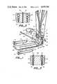
- FIG. 1is a general perspective view of a universal exercising machine of the present invention with various attachments connected to their corresponding points of fixation by dotted lines.
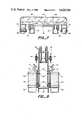
- FIG. 2is a cross-sectional view taken in the direction of lines A--A in FIG. 1.
- FIG. 3is a cross-sectional view taken in the direction of lines B--B in FIG. 1.
- FIG. 4is an exploded perspective view of the machine of FIG. 1 illustrating the attachment and interconnection of various parts thereof.
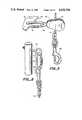
- FIG. 5is a view illustrating the attachment of a hinged pulley of the machine to its frame.
- FIG. 6is a view illustrating the attachment of a cable of the machine to resilient rods thereof.
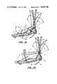
- FIG. 7is a cross-sectional view taken in the direction of lines C--C in FIG. 1.
- FIG. 8is a cross-sectional view taken in the direction of lines D--D in FIG. 1.
- FIG. 9is a partially exploded, fragmentary perspective view of the base portion of the machine.
- FIG. 10is a partial perspective view illustrating a hingeable connection of parts of a slidable bench of the machine.
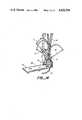
- FIG. 11is a side view of the device of the present invention. broken lines show how the machine collapses for storage or transportation.
- FIGS. 12 to 20illustrate various applications of the exercising machine of the present invention with the bench disconnected from the lower pulley system.
- FIGS. 21 and 22illustrate various applications of the exercising machine of the present invention with the bench slidable on the base.
- FIG. 1is a perspective view of a universal exercising machine of the present invention with various attachments, and to FIGS. 2-11, which show various details and interconnections between parts, the machine comprises a rigid frame or base 10 having an upright U-shaped post 12 and a short horizontal leg 14 rigidly connected to post 12, e.g., by means of triangularly-shaped side corner plates 16.
- An elongated section 18is hinged to leg 14 by means of a hinge 20, which is clearly shown in FIG. 9.
- this hingeable connectionis used for folding the machine into a collapsed position for storage or transportation.
- base section 18In its working or unfolded position, base section 18 is fixed by means of hooks 22 pivotally attached to the sides of base section 18 and engageable with pins 24 which protrude outwardly from horizontal leg 14. Pins 24 are provided with threaded ends 26 for engagement with wing nuts 28 which fix the hooks in their engaged position and, hence base 10 in its unfolded position (FIG. 9).
- foot supports 30which comprise triangularly-shaped blocks, one for each foot on the left and right sides of upright post 12 to which they are attached, e.g., by bolts 32 and 33 and nuts 34 (FIG. 8).
- Upper bolts 33pass through spacers 35 located between the inner sides of foot supports 30 and outer walls of upright posts 12, whereas sheaves 37 are located and rotatably mounted in corresponding lower spaces on bolts 32 between the inner sides of foot supports 30 and outer surfaces of upright post 12. The purpose of sheaves 37 will be explaned later.
- Base 10including horizontal leg 14, corner plates 16, and base 18, can be made of a light metal, such as aluminum or aluminum alloy, or of any other suitable material.
- a retainer 36is inserted into the upper interior portion of U-shaped post 12 and is attached thereto by bolts 41 and nuts 38 (FIG. 2).
- Bolts 41pass through holes 40 provided in retainer 36.
- Retainer 36can be made of a plastic, wood, or metal.
- a second retainer 36ais inserted into the lower interior portion of U-shaped post 12.
- Two symmetrically arranged sets of holes 42 and 42aare drilled or formed by any other suitable method in both retainer 36 and 36a respectively.
- holes 42 and 42a in both retainersare aligned with respect to each other.
- These holesreceive respective cantilevered resilient rods or arms 44, the free ends of which extend upward from retainer 36 and frame or base 10.
- Resilient rods 44may be of different diameters and are preferably made from nylon. Their diameter may vary from 6 mm (1/4") to 51 mm (2").
- Lower ends of resilient rods 44are fixed in retainer 36a by transverse bolts 46 with nuts 48. Bolts 46 pass through aligned holes drilled in retainer 34 and the lower ends of the rods.
- eye bolts 50are attached to the upper ends of resilient rods 44.
- Hand cables 52are connected to eylets of said bolts through detachable links 54 and spring clips 56 (FIG. 6).
- a yoke 58 with a sheave 60is pivotally attached to each side wall of upright post 12 (FIG. 5). This attachment is made through an eye bolt 62, fixed to upright post 12 by nuts 64, and intermediate detachable link 66 which passes through the eyelet of bolt 62 and a hole of yoke 58.
- the connection described abovefunctions as a universal joint which enables the yoke to rotate freely in a wide range.
- Free ends of hand cables 52pass through yoke 58 and are guided by sheaves 60.
- Spring clips 70are attached to the ends of hand cables 52.
- each bracket 74is rigidly fixed to the left and right outer walls of upright post 12, respectively, so that sheaves 72 lie in a transverse vertical plane.
- Foot cables 76 with spring clips 78 and 80 (FIG. 4) at their endsare guided by sheaves 72 so that upper ends of the foot cables can be connected to detachable links 54 on the upper ends of resilient rods 44, whereas their lower ends can be connected to a slidable bench described hereinafter.
- a slidable bench 82comprises a padded wooden frame 84 which is covered with soft vinyl 86 or any other suitable material; covering 86 is attached to the upper surface of the frame.
- Frame 84consists of two parts, 84a and 84b, which are pivotally interconnected by hinges 85 (FIG. 10).
- the benchis provided with two pairs of floor wheels 88 and one pair of base wheels 90. Wheels 88 are mounted in U-shaped brackets 92 arranged on the left and right sides of the bench symmetrically with respect to the longitudinal axis of the exerciser (FIG. 7).
- Base wheels 90roll on rails 94 which are attached to or made integrally with base section 18.
- Eye bolts 96(only one of which is shown in FIG. 4) are engaged with spring clips 80 and are attached to the front end of bench 82 so as to face upright post 12. These eye bolts are used for attaching the bench to foot cables 76.
- Rings 97are attached in various positions to the sides of bench 82. These rings serve as additional means of attaching various elements of the harness.
- the harnessin turn is used to secure an individual body--or handles which the individual may hold with his or her hands while doing leg exercises. This will be explained further with reference to the description of the operation of the exerciser.
- the universal exercising machine of the present inventionis provided with various attachments which broaden its applications and enable an individual to perform an endless variety of physical exercises for developing various groups of his or her muscles (FIG. 1).
- These attachmentscomprise two hand grips 98 (for the left and right hands respectively) attachable to hand cables 52 through spring clips 100 connected to the lower ends of the cables.
- These hand gripsmay have any form convenient for holding.
- each hand grip 98comprises an U-shaped yoke with a handle 102 for the individual's hand and with a ring 104 attachable to spring clip 100. With the use of these hand grips, an individual can work with each hand independently.
- a single stick bar 106can be used instead of separate hand grips 98 when one desires to work with both hands simultaneously.
- a series of rings 108are provided on stick bar 106 for selecting various cable attachment positions with regard to physical abilities of the individual and his or her personal requirements. Rings 108 also can be attached to spring clips 100.
- Another attachmentcomprises two foot straps 110 formed by belts 112 with stirrups 114 at one end and attachment rings at the other end.
- the beltsare adjustable to match the individual's height.
- This attachmentis used for simulating bicycle driving and for stretching, as will be explained further with reference to the machine's operation.
- waist strap 116Another element of the harness is a waist strap 116, which is attached to foot supports 30 (FIG. 1) and is used as an airplane seat belt when the individual exercises in a seating position facing away from upright post 12. Waist strap 116 also can be used for securing an austronaut's body to the machine when the austronaut performs exercises in a spaceship under weightlessness conditions.
- a second belt 118is provided with chains 120 which can be attached, e.g., to spring clips 100 at the ends of cables 52.
- This beltcan be fastened around the individual's waist for one type of exercise, or it can be used as an additional means for attaching the individual's body to the upright post in another type of exercise, i.e., when the individual assumes a sitting position with his or her back to the upright post and belt 118 around his or her chest.
- the universal exercising machine of the present inventionWhen not in use, the universal exercising machine of the present invention can be folded into an inoperative position which is very convenient for transportation or storage.
- wing nuts 28are loosened (FIG. 9), hooks 22 are disconnected from pins 24, and the hinged base section 18 is turned in the direction of the arrows in FIG. 11, along with bench 82, to a position shown by the broken lines in FIG. 11.
- the machineIn a folded state the machine will occupy a space of about 15 ⁇ 30 ⁇ 107 cm (6" ⁇ 12" ⁇ 42”) and this can be rolled into any closet.
- the whole machineweighs 17 kg (38 lb).
- FIGS. 12-22an individual P is shown schematically. Motions of such individual's arms, legs, or body, as well as motions of the movable parts of the machine, are illustrated by broken lines.
- the resistanceis provided by resilient rods 44; these can be used in any combination to suit the individual's requirements and physical abilities. Given below are various types of exercises in connection with various positions of the individual and the use of the various attachments.
- FIG. 12individual P is shown in a standing position facing resilient rods 44.
- the individualholds hand grips 98, the latter being attached to hand cables 52.
- the individualis shown doing shoulder and arm exercises: the individual lifts his or her arms from a straight-down position into positions shown by broken lines, i.e. to the back and up, to the front and up, etc.
- Only one resilient rod 44is employed for ease of illustration, but a plurality can be employed for stronger individuals by connecting the free ends of several adjacent resilient rods 44 together, e.g., by inserting detachable link 54 (FIG. 6) into eyelet bolts 50 of these rods 44.
- FIG. 13illustrates the individual in the same position as shown in FIG. 12.
- Stick bar 106is attached to hand cables 52 instead of separate hand grips 98.
- the individualworks with the bar with both hands simultaneously swinging his or her arms and performing knee-bends, thereby to develop his or her biceps, forearm muscles, and calf muscles.
- FIG. 14the individual is in the same position as in FIG. 12 with belt 118 fastened around his or her waist and attached to hand cables 52. An individual is doing knee-bends so as to work with the thigh muscles.
- FIG. 15an individual is shown on his or her knees facing in a direction opposite to resilient rods 44.
- the individualuses separate hand grips 98 or single stick bar 106 for working the chest and hand muscles.
- FIG. 16illustrates the individual in a seating position facing in a direction opposite to resilient rods 44.
- bench 82is converted into a seat by folding it around hinges 85 (FIG. 10) and leaning part 84b of the bench against upright post 12.
- the individualis fastened by waist strap 116 and works with his or her shoulders, chest and triceps. Both separate hand grips 98 or stick bar 106 can be used in this position.
- FIG. 17shows the individual in a supine position on the bench with his or her head towards upright post 12.
- Separate hand grips 98 or single stick bar 106can be used for exercising in this position.
- Triceps, chest and shoulder musclesare developed by pushing and spreading the individual's arms. This exercises immitates swimming.
- FIG. 18the individual is in the same position as in FIG. 17.
- the individualholds hand grips 98 attached to corresponding rings 97 on the bench.
- the feetare inserted into stirrups 114 of foot straps 110.
- Working the legsthe individual immitates pedaling a bicycle in order to load the heart. It is possible in this position also to immitate running or working, or to spread the legs apart for loading other groups of muscles, as is illustrated by broken lines in FIG. 18.
- FIG. 19the individual is again in a supine position, but facing the resilient rods and with feet planted against foot supports 30.
- the individualdevelops the biceps, triceps, forearm, and shoulder muscles by pulling hand cables 52 or spreading the arm apart.
- FIG. 20the individual is in a sitting position facing the machine.
- the abdomen musclesare loaded by doing situps.
- FIGS. 12-20are performed with bench 82 in a stationary position.
- the exercising machine of the present inventionenables individual P to execute also a variety of physical exercises with the movable bench.
- spring clips 78are attached to the upper ends of resilient rods 44, whereas spring clips 80 are attached to corresponding eye bolts 96 on bench 82.
- the benchappears to be connected to the load through foot cables 76 and can slide with respect to the floor and base 18 on wheels 88 and 90 respectively.
- FIGS. 21 and 22Typical exercises with the slidable bench are illustrated in FIGS. 21 and 22.
- individual Pis shown in the same position as in FIGS. 17 and 18.
- the individualpushes his or her body, together with the bench, away from upright post 12, overcoming the resistance exerted by resilient rods 44.
- the individualexercises his (her) hands, bicepse, triceps, and other muscles.
- FIG. 22the individual assumes the same position as shown in FIG. 19. He or she pushes his or her body by using the legs against foot supports 30, thereby exercising the thigh and calf muscles.
- the resilient rodscan be made of spring metal
- bench framecan be made of plastic material
- other types of connections apart from spring clipscan be used for connecting cables to the resilient rods or other parts of the machine.
- the exercises and positions of the individual's body on the machinewere shown only as illustrative but not limitative. It is obvious also that attachments and harness elements can vary according to individual's needs. Therefore the scope of the invention should be determined, not by the the examples given, but by the appended claims and their legal equivalents.
Landscapes
- Health & Medical Sciences (AREA)
- Life Sciences & Earth Sciences (AREA)
- Biophysics (AREA)
- Orthopedic Medicine & Surgery (AREA)
- General Health & Medical Sciences (AREA)
- Physical Education & Sports Medicine (AREA)
- Rehabilitation Tools (AREA)
- Vending Machines For Individual Products (AREA)
- Eye Examination Apparatus (AREA)
- Acyclic And Carbocyclic Compounds In Medicinal Compositions (AREA)
Abstract
Description
______________________________________ 10 - frame 12 - upright post 14 - horizontal leg 16 - corner plate 18 - base 20 - hinge 22 - hook 24 - pin 26 - threaded end 28 - wing nut 30 -foot support 32, 33 - bolts 34 - nut 35 -36, 36a - retainers 37 - sheave 38 - nut 40 - hole 41 - spacer 42, 42a - holes 44 - resilient rod 46 - transverse bolt 48 - nut 50 - eyelet bolt 52 - hand cable 54 - detachable link 56 - spring clip 58 - yoke 60 - sheave 62 - eye bolt 64 - nut 66 - detachable link 68 - hole 70 - spring clip 72 - sheave 74 - bracket 76 - foot cable 78, 80 - spring clips 82 - slidable bench 84 - bolt 84a, 84b - frame parts 86 - vinyl-covered padding 88 - floor wheel 90 - base wheel 92 - bracket 94 - rail 96 - eye bolt 98 - hand grip 100 - spring clip 102 - handle 104 - ring 106 - stick bar 108 - ring 110 - foot strap 112 - belt 114 - stirrup 116 - waist strap 118 - belt 120 - chain P - exercising individual ______________________________________ wooden frame
Claims (26)
Priority Applications (5)
| Application Number | Priority Date | Filing Date | Title |
|---|---|---|---|
| US06/604,948US4620704A (en) | 1984-04-27 | 1984-04-27 | Universal exercising machine |
| PCT/US1986/000909WO1987006483A1 (en) | 1984-04-27 | 1986-04-25 | Universal exercising machine |
| EP86903058AEP0265430B1 (en) | 1984-04-27 | 1986-04-25 | Universal exercising machine |
| AU58692/86AAU587832B2 (en) | 1984-04-27 | 1986-04-25 | Exercising machine |
| US06/926,950US4725057A (en) | 1984-04-27 | 1986-11-03 | Universal exercising machine |
Applications Claiming Priority (1)
| Application Number | Priority Date | Filing Date | Title |
|---|---|---|---|
| US06/604,948US4620704A (en) | 1984-04-27 | 1984-04-27 | Universal exercising machine |
Related Child Applications (1)
| Application Number | Title | Priority Date | Filing Date |
|---|---|---|---|
| US06/926,950ContinuationUS4725057A (en) | 1984-04-27 | 1986-11-03 | Universal exercising machine |
Publications (1)
| Publication Number | Publication Date |
|---|---|
| US4620704Atrue US4620704A (en) | 1986-11-04 |
Family
ID=24421664
Family Applications (1)
| Application Number | Title | Priority Date | Filing Date |
|---|---|---|---|
| US06/604,948Expired - LifetimeUS4620704A (en) | 1984-04-27 | 1984-04-27 | Universal exercising machine |
Country Status (4)
| Country | Link |
|---|---|
| US (1) | US4620704A (en) |
| EP (1) | EP0265430B1 (en) |
| AU (1) | AU587832B2 (en) |
| WO (1) | WO1987006483A1 (en) |
Cited By (58)
| Publication number | Priority date | Publication date | Assignee | Title |
|---|---|---|---|---|
| US4725057A (en)* | 1984-04-27 | 1988-02-16 | Tessema Shifferaw | Universal exercising machine |
| US4826157A (en)* | 1986-12-10 | 1989-05-02 | Fitzpatrick Patrick C | Physical exercising apparatus |
| US5423730A (en)* | 1989-04-19 | 1995-06-13 | Hirsch; David E. | Physical fitness training apparatus and method of using |
| US5522783A (en)* | 1994-12-27 | 1996-06-04 | Gordon Research & Development, Inc. | Isotonic-isometric device for exercise and physical therapy |
| EP0722751A1 (en)* | 1995-01-23 | 1996-07-24 | Gordon Research and Development, Inc. | Isotonic/isometric exercise and therapy system |
| US5813953A (en)* | 1995-10-18 | 1998-09-29 | Whipple; David L. | Portable exercise apparatus and method of use |
| US6030323A (en)* | 1998-03-25 | 2000-02-29 | Fontenot; Anthony | Exercise apparatus |
| US6113522A (en)* | 1993-05-26 | 2000-09-05 | Robert N. Montgomery | Exercise apparatus |
| US6561960B2 (en)* | 2001-01-22 | 2003-05-13 | Randall T. Webber | Exercise arm apparatus for exercise machine |
| US6585626B2 (en)* | 2000-12-18 | 2003-07-01 | Stamina Products, Inc. | Bench exerciser with upwardly diverging bungee cord supports |
| US20030232707A1 (en)* | 2002-06-14 | 2003-12-18 | Icon Ip, Inc. | Exercise device with centrally mounted resistance rod |
| US20040166999A1 (en)* | 2003-02-20 | 2004-08-26 | Dodge David J. | Exercise equipment resistance unit |
| US20040198571A1 (en)* | 2003-04-02 | 2004-10-07 | Brigham Young University. | Substantially constant-force exercise machine |
| US20040224827A1 (en)* | 2003-05-07 | 2004-11-11 | Peter Ashley | Selectable force exercise machine |
| US20050037904A1 (en)* | 2003-08-12 | 2005-02-17 | Shih-Chang Chang | Body exercising device |
| US20050043155A1 (en)* | 2003-06-07 | 2005-02-24 | Yannitte Thomas Anthony A.J. | Exercise apparatus |
| WO2005025682A1 (en)* | 2003-08-25 | 2005-03-24 | Icon Ip, Inc. | Exercise device with centrally mounted resistance rod and automatic weight selector apparatus |
| WO2005102465A1 (en)* | 2004-04-21 | 2005-11-03 | Laser Fit Di Musso Giuseppe | Improved sporting apparatus |
| US20060058158A1 (en)* | 2004-09-10 | 2006-03-16 | Pentagon South Inc. | Universal fitness apparatus |
| US7041041B1 (en) | 2002-03-21 | 2006-05-09 | Robert Scott Evans | Exercise equipment |
| US7070545B2 (en) | 2002-07-01 | 2006-07-04 | Nautilus, Inc. | Leg press and abdominal crunch exercise machine |
| US7083554B1 (en) | 1997-02-27 | 2006-08-01 | Nautilus, Inc. | Exercise machine with infinite position range limiter and automatic belt tensioning system |
| US20060189462A1 (en)* | 2005-01-14 | 2006-08-24 | Nautilus, Inc. | Exercise device |
| US7097593B2 (en) | 2003-08-11 | 2006-08-29 | Nautilus, Inc. | Combination of treadmill and stair climbing machine |
| US7108641B2 (en) | 2000-05-03 | 2006-09-19 | Nautilus, Inc. | Exercise equipment with multi-positioning handles |
| US7115080B2 (en) | 2002-08-01 | 2006-10-03 | Nautilus, Inc. | Collapsible seat for combination hack squat and leg press machine |
| US20070054790A1 (en)* | 2003-02-20 | 2007-03-08 | Alliance Design & Development Group, Inc. | Exercise apparatus resistance unit |
| US20070072752A1 (en)* | 2005-09-29 | 2007-03-29 | Koch Kregg A | Exercise Apparatus |
| US7223216B1 (en)* | 2000-12-18 | 2007-05-29 | Stamina Products, Inc. | Exerciser with multiple bungee cord resistance and enhanced bench movements |
| US20080039301A1 (en)* | 2006-07-19 | 2008-02-14 | Adam Halbridge | Exercise Apparatus |
| US7429236B2 (en) | 2003-08-25 | 2008-09-30 | Icon Ip, Inc. | Exercise device with single resilient elongate rod and weight selector controller |
| US20090054214A1 (en)* | 2005-09-29 | 2009-02-26 | Michael Shannon Kadar | Exercise apparatus |
| US20100144501A1 (en)* | 2008-12-05 | 2010-06-10 | Nahome Berhanu | Articulating exercise harness system |
| US7922635B2 (en) | 2000-03-10 | 2011-04-12 | Nautilus, Inc. | Adjustable-load unitary multi-position bench exercise unit |
| US20110124476A1 (en)* | 2009-11-24 | 2011-05-26 | Terry Reed Holley | Whole body exercise apparatus for use with elastic spherical ball |
| US20110143898A1 (en)* | 2009-12-14 | 2011-06-16 | Hill-Rom Services, Inc. | Patient support apparatuses with exercise functionalities |
| WO2015006378A1 (en) | 2013-07-09 | 2015-01-15 | Threlfall John | External structural brace apparatus |
| US9038218B1 (en) | 2014-01-15 | 2015-05-26 | Hill-Rom Services, Inc. | Person support apparatuses with selectively coupled foot sections |
| US9132051B2 (en) | 2014-01-15 | 2015-09-15 | Hill-Rom Services, Inc. | Person support apparatuses with exercise functionalities |
| WO2015130779A3 (en)* | 2014-02-25 | 2015-10-15 | Zanyk Marien | Willow workout device |
| USD778999S1 (en) | 2015-02-25 | 2017-02-14 | W2Designs, LLC | Isometric exercise and stretching support stand |
| US9737747B1 (en) | 2012-01-11 | 2017-08-22 | Alliance Design And Development Group, Inc. | Methods of adjusting stiffness and flexibility in devices, apparatus and equipment |
| US9814927B2 (en) | 2016-02-26 | 2017-11-14 | Leon Forystek | Abdominal exercise apparatus |
| US10188890B2 (en) | 2013-12-26 | 2019-01-29 | Icon Health & Fitness, Inc. | Magnetic resistance mechanism in a cable machine |
| US10232211B1 (en) | 2015-07-16 | 2019-03-19 | Kregg Alan Koch | Exercise apparatus |
| US10252109B2 (en) | 2016-05-13 | 2019-04-09 | Icon Health & Fitness, Inc. | Weight platform treadmill |
| US10279212B2 (en) | 2013-03-14 | 2019-05-07 | Icon Health & Fitness, Inc. | Strength training apparatus with flywheel and related methods |
| US10293211B2 (en) | 2016-03-18 | 2019-05-21 | Icon Health & Fitness, Inc. | Coordinated weight selection |
| WO2019100117A1 (en)* | 2017-11-23 | 2019-05-31 | Fatty Industries Pty Ltd | Exercise bay and exercise apparatus for use with same |
| US10398921B1 (en) | 2012-01-11 | 2019-09-03 | Alliance Design And Development Group, Inc. | Methods of adjusting stiffness and flexibility in devices, apparatus and equipment |
| US10426989B2 (en) | 2014-06-09 | 2019-10-01 | Icon Health & Fitness, Inc. | Cable system incorporated into a treadmill |
| US10441840B2 (en) | 2016-03-18 | 2019-10-15 | Icon Health & Fitness, Inc. | Collapsible strength exercise machine |
| US10449416B2 (en) | 2015-08-26 | 2019-10-22 | Icon Health & Fitness, Inc. | Strength exercise mechanisms |
| US10661114B2 (en) | 2016-11-01 | 2020-05-26 | Icon Health & Fitness, Inc. | Body weight lift mechanism on treadmill |
| US10874567B2 (en) | 2014-03-11 | 2020-12-29 | Hill-Rom Services, Inc. | Patient bed having footboard pedal apparatus for physical therapy |
| US10940360B2 (en) | 2015-08-26 | 2021-03-09 | Icon Health & Fitness, Inc. | Strength exercise mechanisms |
| US11324984B2 (en) | 2020-06-29 | 2022-05-10 | OK Engineering Inc. | Resistance band exercise machine |
| US11963918B2 (en) | 2020-04-20 | 2024-04-23 | Hill-Rom Services, Inc. | Patient bed having active motion exercise |
Citations (9)
| Publication number | Priority date | Publication date | Assignee | Title |
|---|---|---|---|---|
| US1585748A (en)* | 1925-04-28 | 1926-05-25 | Albert C Wendelken | Exercising apparatus |
| GB466901A (en)* | 1936-01-03 | 1937-06-08 | Leslie Whittington Landon | Improvements in or relating to exercising apparatus |
| US3342485A (en)* | 1965-03-18 | 1967-09-19 | Gaul Martin | Exercising bench comprising hinged and adjustable seating portions |
| US3567219A (en)* | 1969-05-16 | 1971-03-02 | Timothy G Foster | Universal physical exercising device |
| US3658327A (en)* | 1971-03-10 | 1972-04-25 | Clifford S Thiede | Pull type exercising device |
| DE2346105A1 (en)* | 1973-09-13 | 1975-03-27 | Ertl Josef | Hand gripped movement exercise apparatus - consisting of two sprung sticks connected by a flexible rod and distance pieces |
| US3981500A (en)* | 1974-10-17 | 1976-09-21 | Ryan Vernon L | Adjustable support apparatus |
| US4063727A (en)* | 1976-07-19 | 1977-12-20 | Hall James A | Arm wrestling exercise device |
| US4494662A (en)* | 1983-03-04 | 1985-01-22 | Clymer Ronald S | Mounted spring device for resisting flexing |
Family Cites Families (2)
| Publication number | Priority date | Publication date | Assignee | Title |
|---|---|---|---|---|
| GB325435A (en)* | 1929-05-10 | 1930-02-20 | John Malcolm Thomson | Improvements in and relating to exercising apparatus |
| FR824654A (en)* | 1936-02-25 | 1938-02-14 | Rational training apparatus |
- 1984
- 1984-04-27USUS06/604,948patent/US4620704A/ennot_activeExpired - Lifetime
- 1986
- 1986-04-25AUAU58692/86Apatent/AU587832B2/ennot_activeExpired
- 1986-04-25EPEP86903058Apatent/EP0265430B1/ennot_activeExpired - Lifetime
- 1986-04-25WOPCT/US1986/000909patent/WO1987006483A1/enactiveIP Right Grant
Patent Citations (9)
| Publication number | Priority date | Publication date | Assignee | Title |
|---|---|---|---|---|
| US1585748A (en)* | 1925-04-28 | 1926-05-25 | Albert C Wendelken | Exercising apparatus |
| GB466901A (en)* | 1936-01-03 | 1937-06-08 | Leslie Whittington Landon | Improvements in or relating to exercising apparatus |
| US3342485A (en)* | 1965-03-18 | 1967-09-19 | Gaul Martin | Exercising bench comprising hinged and adjustable seating portions |
| US3567219A (en)* | 1969-05-16 | 1971-03-02 | Timothy G Foster | Universal physical exercising device |
| US3658327A (en)* | 1971-03-10 | 1972-04-25 | Clifford S Thiede | Pull type exercising device |
| DE2346105A1 (en)* | 1973-09-13 | 1975-03-27 | Ertl Josef | Hand gripped movement exercise apparatus - consisting of two sprung sticks connected by a flexible rod and distance pieces |
| US3981500A (en)* | 1974-10-17 | 1976-09-21 | Ryan Vernon L | Adjustable support apparatus |
| US4063727A (en)* | 1976-07-19 | 1977-12-20 | Hall James A | Arm wrestling exercise device |
| US4494662A (en)* | 1983-03-04 | 1985-01-22 | Clymer Ronald S | Mounted spring device for resisting flexing |
Cited By (83)
| Publication number | Priority date | Publication date | Assignee | Title |
|---|---|---|---|---|
| US4725057A (en)* | 1984-04-27 | 1988-02-16 | Tessema Shifferaw | Universal exercising machine |
| US4826157A (en)* | 1986-12-10 | 1989-05-02 | Fitzpatrick Patrick C | Physical exercising apparatus |
| US5423730A (en)* | 1989-04-19 | 1995-06-13 | Hirsch; David E. | Physical fitness training apparatus and method of using |
| US6113522A (en)* | 1993-05-26 | 2000-09-05 | Robert N. Montgomery | Exercise apparatus |
| US5522783A (en)* | 1994-12-27 | 1996-06-04 | Gordon Research & Development, Inc. | Isotonic-isometric device for exercise and physical therapy |
| US5674166A (en)* | 1994-12-27 | 1997-10-07 | Gordon Research & Development, Inc. | Isotonic or isometric exercise and therapy system |
| EP0722751A1 (en)* | 1995-01-23 | 1996-07-24 | Gordon Research and Development, Inc. | Isotonic/isometric exercise and therapy system |
| US5813953A (en)* | 1995-10-18 | 1998-09-29 | Whipple; David L. | Portable exercise apparatus and method of use |
| US7083554B1 (en) | 1997-02-27 | 2006-08-01 | Nautilus, Inc. | Exercise machine with infinite position range limiter and automatic belt tensioning system |
| US6030323A (en)* | 1998-03-25 | 2000-02-29 | Fontenot; Anthony | Exercise apparatus |
| US7922635B2 (en) | 2000-03-10 | 2011-04-12 | Nautilus, Inc. | Adjustable-load unitary multi-position bench exercise unit |
| US7108641B2 (en) | 2000-05-03 | 2006-09-19 | Nautilus, Inc. | Exercise equipment with multi-positioning handles |
| US7608028B2 (en) | 2000-05-03 | 2009-10-27 | Nautilus, Inc. | Exercise equipment with multi-positioning handles |
| US6585626B2 (en)* | 2000-12-18 | 2003-07-01 | Stamina Products, Inc. | Bench exerciser with upwardly diverging bungee cord supports |
| US7223216B1 (en)* | 2000-12-18 | 2007-05-29 | Stamina Products, Inc. | Exerciser with multiple bungee cord resistance and enhanced bench movements |
| US6561960B2 (en)* | 2001-01-22 | 2003-05-13 | Randall T. Webber | Exercise arm apparatus for exercise machine |
| US7041041B1 (en) | 2002-03-21 | 2006-05-09 | Robert Scott Evans | Exercise equipment |
| US7250022B2 (en) | 2002-06-14 | 2007-07-31 | Dalebout William T | Exercise device with centrally mounted resistance rod |
| US7798946B2 (en) | 2002-06-14 | 2010-09-21 | Icon Ip, Inc. | Exercise device with centrally mounted resistance rod |
| US20030232707A1 (en)* | 2002-06-14 | 2003-12-18 | Icon Ip, Inc. | Exercise device with centrally mounted resistance rod |
| US7070545B2 (en) | 2002-07-01 | 2006-07-04 | Nautilus, Inc. | Leg press and abdominal crunch exercise machine |
| US7608022B2 (en) | 2002-07-01 | 2009-10-27 | Nautilus, Inc. | Leg press and abdominal crunch exercise machine |
| US7115080B2 (en) | 2002-08-01 | 2006-10-03 | Nautilus, Inc. | Collapsible seat for combination hack squat and leg press machine |
| US7291100B2 (en) | 2003-02-20 | 2007-11-06 | Alliance Design & Design Development Group, Inc. | Exercise equipment resistance unit |
| US7762935B2 (en)* | 2003-02-20 | 2010-07-27 | Doble William C | Exercise apparatus resistance unit |
| US20070054790A1 (en)* | 2003-02-20 | 2007-03-08 | Alliance Design & Development Group, Inc. | Exercise apparatus resistance unit |
| US20040166999A1 (en)* | 2003-02-20 | 2004-08-26 | Dodge David J. | Exercise equipment resistance unit |
| US7060012B2 (en)* | 2003-04-02 | 2006-06-13 | Brigham Young University | Substantially constant-force exercise machine |
| US20040198571A1 (en)* | 2003-04-02 | 2004-10-07 | Brigham Young University. | Substantially constant-force exercise machine |
| US7014599B2 (en) | 2003-05-07 | 2006-03-21 | Peter Ashley | Selectable force exercise machine |
| US20040224827A1 (en)* | 2003-05-07 | 2004-11-11 | Peter Ashley | Selectable force exercise machine |
| US20050043155A1 (en)* | 2003-06-07 | 2005-02-24 | Yannitte Thomas Anthony A.J. | Exercise apparatus |
| US7097593B2 (en) | 2003-08-11 | 2006-08-29 | Nautilus, Inc. | Combination of treadmill and stair climbing machine |
| US20050037904A1 (en)* | 2003-08-12 | 2005-02-17 | Shih-Chang Chang | Body exercising device |
| US7429236B2 (en) | 2003-08-25 | 2008-09-30 | Icon Ip, Inc. | Exercise device with single resilient elongate rod and weight selector controller |
| US7537552B2 (en)* | 2003-08-25 | 2009-05-26 | Icon Ip, Inc. (State Of Delaware) | Exercise device with centrally mounted resistance rod and automatic weight selector apparatus |
| WO2005025682A1 (en)* | 2003-08-25 | 2005-03-24 | Icon Ip, Inc. | Exercise device with centrally mounted resistance rod and automatic weight selector apparatus |
| WO2005102465A1 (en)* | 2004-04-21 | 2005-11-03 | Laser Fit Di Musso Giuseppe | Improved sporting apparatus |
| US7147591B2 (en) | 2004-09-10 | 2006-12-12 | Pentagon South Inc. | Universal fitness apparatus |
| US20060058158A1 (en)* | 2004-09-10 | 2006-03-16 | Pentagon South Inc. | Universal fitness apparatus |
| US20060189462A1 (en)* | 2005-01-14 | 2006-08-24 | Nautilus, Inc. | Exercise device |
| US7892155B2 (en) | 2005-01-14 | 2011-02-22 | Nautilus, Inc. | Exercise device |
| US20090054214A1 (en)* | 2005-09-29 | 2009-02-26 | Michael Shannon Kadar | Exercise apparatus |
| US8137249B2 (en)* | 2005-09-29 | 2012-03-20 | Core Stix Fitness Llc | Exercise apparatus |
| US7704199B2 (en)* | 2005-09-29 | 2010-04-27 | Core Stix Fitness, Llc | Exercise apparatus |
| US20100273615A1 (en)* | 2005-09-29 | 2010-10-28 | Kregg Alan Koch | Exercise apparatus |
| US7878956B2 (en) | 2005-09-29 | 2011-02-01 | Core Stix Fitness, Llc | Exercise apparatus |
| US20070072752A1 (en)* | 2005-09-29 | 2007-03-29 | Koch Kregg A | Exercise Apparatus |
| US8500612B2 (en) | 2005-09-29 | 2013-08-06 | Core Stix Fitness Llc | Exercise apparatus |
| US20080039301A1 (en)* | 2006-07-19 | 2008-02-14 | Adam Halbridge | Exercise Apparatus |
| US20100144501A1 (en)* | 2008-12-05 | 2010-06-10 | Nahome Berhanu | Articulating exercise harness system |
| US7946967B2 (en) | 2008-12-05 | 2011-05-24 | Nahome Berhanu | Articulating exercise harness system |
| US9242139B2 (en) | 2009-11-24 | 2016-01-26 | Terry Reed Holley | Whole body exercise apparatus for use with elastic spherical ball |
| US20110124476A1 (en)* | 2009-11-24 | 2011-05-26 | Terry Reed Holley | Whole body exercise apparatus for use with elastic spherical ball |
| US20110143898A1 (en)* | 2009-12-14 | 2011-06-16 | Hill-Rom Services, Inc. | Patient support apparatuses with exercise functionalities |
| US8858409B2 (en)* | 2009-12-14 | 2014-10-14 | Hill-Rom Services, Inc. | Patient support apparatuses with exercise functionalities |
| US9125785B2 (en) | 2009-12-14 | 2015-09-08 | Hill-Rom Services, Inc. | Patient support apparatuses with exercise functionalities |
| US10398921B1 (en) | 2012-01-11 | 2019-09-03 | Alliance Design And Development Group, Inc. | Methods of adjusting stiffness and flexibility in devices, apparatus and equipment |
| US9737747B1 (en) | 2012-01-11 | 2017-08-22 | Alliance Design And Development Group, Inc. | Methods of adjusting stiffness and flexibility in devices, apparatus and equipment |
| US10279212B2 (en) | 2013-03-14 | 2019-05-07 | Icon Health & Fitness, Inc. | Strength training apparatus with flywheel and related methods |
| WO2015006378A1 (en) | 2013-07-09 | 2015-01-15 | Threlfall John | External structural brace apparatus |
| US10188890B2 (en) | 2013-12-26 | 2019-01-29 | Icon Health & Fitness, Inc. | Magnetic resistance mechanism in a cable machine |
| US10646389B2 (en) | 2014-01-15 | 2020-05-12 | Liko Research & Development Ab | Person support apparatuses with selectively coupled foot sections |
| US9132051B2 (en) | 2014-01-15 | 2015-09-15 | Hill-Rom Services, Inc. | Person support apparatuses with exercise functionalities |
| US11452650B2 (en) | 2014-01-15 | 2022-09-27 | Hill-Rom Services, Inc. | Person support apparatuses with selectively coupled foot sections |
| US9038218B1 (en) | 2014-01-15 | 2015-05-26 | Hill-Rom Services, Inc. | Person support apparatuses with selectively coupled foot sections |
| WO2015130779A3 (en)* | 2014-02-25 | 2015-10-15 | Zanyk Marien | Willow workout device |
| US10549139B2 (en) | 2014-02-25 | 2020-02-04 | W2Designs Llc | Isometric exercise and stretching apparatus |
| US10874567B2 (en) | 2014-03-11 | 2020-12-29 | Hill-Rom Services, Inc. | Patient bed having footboard pedal apparatus for physical therapy |
| US10426989B2 (en) | 2014-06-09 | 2019-10-01 | Icon Health & Fitness, Inc. | Cable system incorporated into a treadmill |
| USD778999S1 (en) | 2015-02-25 | 2017-02-14 | W2Designs, LLC | Isometric exercise and stretching support stand |
| US10232211B1 (en) | 2015-07-16 | 2019-03-19 | Kregg Alan Koch | Exercise apparatus |
| US10449416B2 (en) | 2015-08-26 | 2019-10-22 | Icon Health & Fitness, Inc. | Strength exercise mechanisms |
| US10940360B2 (en) | 2015-08-26 | 2021-03-09 | Icon Health & Fitness, Inc. | Strength exercise mechanisms |
| US9814927B2 (en) | 2016-02-26 | 2017-11-14 | Leon Forystek | Abdominal exercise apparatus |
| US10441840B2 (en) | 2016-03-18 | 2019-10-15 | Icon Health & Fitness, Inc. | Collapsible strength exercise machine |
| US10293211B2 (en) | 2016-03-18 | 2019-05-21 | Icon Health & Fitness, Inc. | Coordinated weight selection |
| US10252109B2 (en) | 2016-05-13 | 2019-04-09 | Icon Health & Fitness, Inc. | Weight platform treadmill |
| US10661114B2 (en) | 2016-11-01 | 2020-05-26 | Icon Health & Fitness, Inc. | Body weight lift mechanism on treadmill |
| WO2019100117A1 (en)* | 2017-11-23 | 2019-05-31 | Fatty Industries Pty Ltd | Exercise bay and exercise apparatus for use with same |
| US11963918B2 (en) | 2020-04-20 | 2024-04-23 | Hill-Rom Services, Inc. | Patient bed having active motion exercise |
| US12186248B2 (en) | 2020-04-20 | 2025-01-07 | Hill-Rom Services, Inc. | Patient bed having active motion exercise |
| US11324984B2 (en) | 2020-06-29 | 2022-05-10 | OK Engineering Inc. | Resistance band exercise machine |
Also Published As
| Publication number | Publication date |
|---|---|
| AU587832B2 (en) | 1989-08-31 |
| EP0265430B1 (en) | 1993-04-07 |
| EP0265430A1 (en) | 1988-05-04 |
| EP0265430A4 (en) | 1990-06-26 |
| WO1987006483A1 (en) | 1987-11-05 |
| AU5869286A (en) | 1987-11-24 |
Similar Documents
| Publication | Publication Date | Title |
|---|---|---|
| US4620704A (en) | Universal exercising machine | |
| US4725057A (en) | Universal exercising machine | |
| US7322907B2 (en) | Exercise system using exercise resistance cables | |
| US8672817B2 (en) | Exercise system using exercise resistance cables | |
| US8721507B2 (en) | Multi-planar resistance band exercise system | |
| US5624360A (en) | Total gym | |
| US7775949B2 (en) | Shoulder stretcher assembly | |
| US7204790B2 (en) | Multi-sport training machine with inclined monorail and roller carriage | |
| US4198044A (en) | Exercise board | |
| US5468205A (en) | Portable door mounted exercise apparatus | |
| US5730688A (en) | Portable abdominal-lumbar exercise device | |
| US10532239B1 (en) | Apparatus for exercising | |
| US20230118879A1 (en) | Fitness exercise apparatus | |
| US20040014570A1 (en) | Exercise bench | |
| EP4166203A1 (en) | Fitness exercise apparatus | |
| CA1264778A (en) | Universal exercising machine | |
| DE3688254T2 (en) | UNIVERSAL EXERCISE EQUIPMENT. | |
| RU1818112C (en) | Training equipment | |
| KR20070017139A (en) | Exercise system using exercise resistance cable |
Legal Events
| Date | Code | Title | Description |
|---|---|---|---|
| STCF | Information on status: patent grant | Free format text:PATENTED CASE | |
| AS | Assignment | Owner name:DOSHO DESIGNS, INC., A CORP. OF CA Free format text:LICENSE;ASSIGNOR:SHIFFERAW, TESSEMA D.;REEL/FRAME:004740/0501 Effective date:19860325 Owner name:BOW-FLEX INTERNATIONAL, INC., A CORP. OF CA Free format text:LICENSE;ASSIGNOR:SHIFFERAW, TESSEMA D.;REEL/FRAME:004740/0514 Effective date:19860325 Owner name:OLSEN, MARY E., P.O. BOX 977, NORFOLK, NE 68701 Free format text:SECURITY INTEREST;ASSIGNORS:BOW-FLEX OF AMERICA, INC.,;BOW-FLEX INTERNATIONAL, INC.;REEL/FRAME:004740/0528 Effective date:19870612 Owner name:OLSEN, MARY E.,NEBRASKA Free format text:SECURITY INTEREST;ASSIGNORS:BOW-FLEX OF AMERICA, INC.,;BOW-FLEX INTERNATIONAL, INC.;REEL/FRAME:004740/0528 Effective date:19870612 | |
| AS | Assignment | Owner name:BOW-FLEX OF AMERICA, INC. Free format text:CHANGE OF NAME;ASSIGNOR:DOSHO DESIGNS, INC.;REEL/FRAME:004770/0750 Effective date:19860325 | |
| AS | Assignment | Owner name:BOW-FLEX OF AMERICA, INC., 1153 TRITON DRIVE, SUIT Free format text:ASSIGNMENT OF ASSIGNORS INTEREST;ASSIGNOR:SHIFFERAW, TESSEMA, D.,;REEL/FRAME:004850/0435 Effective date:19880411 Owner name:BOW-FLEX OF AMERICA, INC.,CALIFORNIA Free format text:ASSIGNMENT OF ASSIGNORS INTEREST;ASSIGNOR:SHIFFERAW, TESSEMA, D.,;REEL/FRAME:004850/0435 Effective date:19880411 | |
| AS | Assignment | Owner name:OLSEN, MARY, E., P.O. BOX 977, NORFOLK, NEBRASKA 6 Free format text:SECURITY INTEREST;ASSIGNOR:BOW-FLEX OF AMERICA, INC.,;REEL/FRAME:004908/0348 Effective date:19880511 Owner name:OLSEN, MARY, E.,NEBRASKA Free format text:SECURITY INTEREST;ASSIGNOR:BOW-FLEX OF AMERICA, INC.,;REEL/FRAME:004908/0348 Effective date:19880511 | |
| FPAY | Fee payment | Year of fee payment:4 | |
| FEPP | Fee payment procedure | Free format text:PAYOR NUMBER ASSIGNED (ORIGINAL EVENT CODE: ASPN); ENTITY STATUS OF PATENT OWNER: SMALL ENTITY | |
| FPAY | Fee payment | Year of fee payment:8 | |
| AS | Assignment | Owner name:BOW FLEX, INC., WASHINGTON Free format text:ASSIGNMENT OF ASSIGNORS INTEREST;ASSIGNOR:BOW-FLEX OF AMERICA, INC.;REEL/FRAME:007521/0818 Effective date:19930127 | |
| FPAY | Fee payment | Year of fee payment:12 | |
| SULP | Surcharge for late payment | ||
| AS | Assignment | Owner name:DIRECT FOCUS, INC., WASHINGTON Free format text:CHANGE OF NAME;ASSIGNOR:BOW FLEX, INC.;REEL/FRAME:011712/0073 Effective date:19980513 | |
| AS | Assignment | Owner name:THE NAUTILUS GROUP, INC., WASHINGTON Free format text:CHANGE OF NAME;ASSIGNOR:DIRECT FOCUS, INC.;REEL/FRAME:013305/0364 Effective date:20020508 | |
| AS | Assignment | Owner name:NAUTILUS, INC., WASHINGTON Free format text:ASSIGNMENT OF ASSIGNORS INTEREST;ASSIGNOR:NAUTILUS GROUP, INC., THE;REEL/FRAME:015372/0189 Effective date:20041028 | |
| AS | Assignment | Owner name:BOWFLEX INC., WASHINGTON Free format text:CHANGE OF NAME;ASSIGNOR:NAUTILUS, INC.;REEL/FRAME:065820/0610 Effective date:20231017 |