US4620285A - Sonar ranging/light detection system for use in a robot - Google Patents
Sonar ranging/light detection system for use in a robotDownload PDFInfo
- Publication number
- US4620285A US4620285AUS06/603,471US60347184AUS4620285AUS 4620285 AUS4620285 AUS 4620285AUS 60347184 AUS60347184 AUS 60347184AUS 4620285 AUS4620285 AUS 4620285A
- Authority
- US
- United States
- Prior art keywords
- controller
- robot
- accordance
- sensor system
- coupled
- Prior art date
- Legal status (The legal status is an assumption and is not a legal conclusion. Google has not performed a legal analysis and makes no representation as to the accuracy of the status listed.)
- Expired - Fee Related
Links
- 238000001514detection methodMethods0.000titleabstractdescription22
- 238000013016dampingMethods0.000claimsabstractdescription9
- 238000002592echocardiographyMethods0.000claimsabstractdescription6
- 230000003287optical effectEffects0.000claimsdescription13
- 230000001419dependent effectEffects0.000claimsdescription9
- 230000008878couplingEffects0.000claimsdescription5
- 238000010168coupling processMethods0.000claimsdescription5
- 238000005859coupling reactionMethods0.000claimsdescription5
- 238000012545processingMethods0.000claimsdescription3
- 230000004044responseEffects0.000claimsdescription2
- 230000005540biological transmissionEffects0.000claims1
- 238000005259measurementMethods0.000abstractdescription15
- 239000004065semiconductorSubstances0.000abstractdescription2
- 238000000034methodMethods0.000abstract1
- 230000001953sensory effectEffects0.000abstract1
- 230000006641stabilisationEffects0.000abstract1
- 238000011105stabilizationMethods0.000abstract1
- 238000004804windingMethods0.000description12
- 230000006870functionEffects0.000description9
- 239000003990capacitorSubstances0.000description7
- 238000010586diagramMethods0.000description4
- 238000006073displacement reactionMethods0.000description4
- 230000001934delayEffects0.000description3
- 238000013461designMethods0.000description3
- 238000012986modificationMethods0.000description3
- 230000004048modificationEffects0.000description3
- 230000007935neutral effectEffects0.000description3
- 230000001276controlling effectEffects0.000description2
- 239000013078crystalSubstances0.000description2
- 230000000977initiatory effectEffects0.000description2
- 230000007246mechanismEffects0.000description2
- 230000002093peripheral effectEffects0.000description2
- 235000014676Phragmites communisNutrition0.000description1
- 230000002457bidirectional effectEffects0.000description1
- 230000008859changeEffects0.000description1
- 238000012937correctionMethods0.000description1
- 229910003460diamondInorganic materials0.000description1
- 239000010432diamondSubstances0.000description1
- 230000009977dual effectEffects0.000description1
- 230000007613environmental effectEffects0.000description1
- 230000000644propagated effectEffects0.000description1
- 230000001105regulatory effectEffects0.000description1
- 230000003252repetitive effectEffects0.000description1
- 238000012360testing methodMethods0.000description1
Images


Classifications
- B—PERFORMING OPERATIONS; TRANSPORTING
- B25—HAND TOOLS; PORTABLE POWER-DRIVEN TOOLS; MANIPULATORS
- B25J—MANIPULATORS; CHAMBERS PROVIDED WITH MANIPULATION DEVICES
- B25J19/00—Accessories fitted to manipulators, e.g. for monitoring, for viewing; Safety devices combined with or specially adapted for use in connection with manipulators
- B25J19/02—Sensing devices
- B25J19/021—Optical sensing devices
- B—PERFORMING OPERATIONS; TRANSPORTING
- B25—HAND TOOLS; PORTABLE POWER-DRIVEN TOOLS; MANIPULATORS
- B25J—MANIPULATORS; CHAMBERS PROVIDED WITH MANIPULATION DEVICES
- B25J19/00—Accessories fitted to manipulators, e.g. for monitoring, for viewing; Safety devices combined with or specially adapted for use in connection with manipulators
- B25J19/02—Sensing devices
- B25J19/026—Acoustical sensing devices
- G—PHYSICS
- G01—MEASURING; TESTING
- G01S—RADIO DIRECTION-FINDING; RADIO NAVIGATION; DETERMINING DISTANCE OR VELOCITY BY USE OF RADIO WAVES; LOCATING OR PRESENCE-DETECTING BY USE OF THE REFLECTION OR RERADIATION OF RADIO WAVES; ANALOGOUS ARRANGEMENTS USING OTHER WAVES
- G01S15/00—Systems using the reflection or reradiation of acoustic waves, e.g. sonar systems
- G01S15/86—Combinations of sonar systems with lidar systems; Combinations of sonar systems with systems not using wave reflection
Definitions
- This systemrelates generally to multi-detector sensing systems and is particularly directed to a combination sonar and light detection system for use in a robot.
- a mobile robotIn addition to their limited capacity for performing complex operations, the high cost of the typical mobile robot has also contributed to their limited acceptance and usage.
- One component which has substantially contributed to the relatively high cost of most mobile robotsis the sensor system.
- a mobile robotIn order to perform tasks in more than one location, a mobile robot must be capable of sensing its present location and of determining where to proceed to in order to perform a subsequent operation. To date, this has been accomplished by means of several sensors positioned at various locations on the robot to permit it to locate itself with respect to other objects in its immediate vicinity. These sensing devices are generally of the acoustical or optical type and the robot is typically provided with a complex combination of detectors. Each detector incorporated in the robot, of course, increases its cost. Therefore, in the design and operation of a mobile robot it is desirable to provide a maximum sensing capability with a minimum number of relatively simple, inexpensive sensors.
- the present inventionis intended to provide such a capability in a mobile robot by means of a single transmit/receive device capable of 360° coverage around the robot and which may simultaneously be used with sonar and optical detectors.
- Yet another object of the present inventionis to provide an omnidirectional sensing capability in a mobile robot using a single transmit/receive device.
- a further object of the present inventionis to provide a sensor system for a mobile robot capable of continuous 360° rotation, sector scan, and pointing to a designated direction.
- a still further object of the present inventionis to provide a dual mode sensor for a mobile robot capable of providing 360° coverage as well as information relating to the immediate path of travel of the robot.
- FIG. 1is a simplified schematic diagram of a sonar ranging/light detection system for use in a mobile robot in accordance with the present invention
- FIG. 2is a circuit diagram in combined block and schematic form of a sonar ranging/light detection system for use in the robot of FIG. 1 in accordance with the presnt invention
- FIGS. 3, 4, 5a and 5bpresent flow charts illustrating the operation of a sonar ranging/light detection system under the control of a microcomputer in accordance with a preferred embodiment of the present invention.
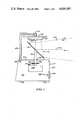
- FIG. 1there is shown a simplified schematic diagram of a sonar ranging/light detection system 112 in accordance with a preferred embodiment of the present invention.
- the sonar ranging/light detection system 112is positioned in a mobile robot 110 which includes a housing 117. Rotationally coupled to a lower portion of housing 117 are a plurality of wheels 114 which permit the robot 110 to be displaced upon a support surface (not shown). Also provided within housing 117 are drive means (also not shown in the figure) coupled to wheels 114 for initiating the rotation thereof and the displacement of robot 110. Since the drive mechanism used to propel the robot 110 does not form a part of the present invention, it is not further discussed herein.
- the robot housingincludes an upper panel 132 which includes first and second apertures 134, 135 therein. Positioned within the first aperture 134 is a rotating support shaft 130 which is coupled to and rotationally displaced by a stepper motor 140. Also coupled to rotating support shaft 130 is a slotted disc 136. Positioned immediately adjacent slotted disc 136 is an optical switch 138. Optical switch 138 is capable of detecting the slot within slotted disc 136 and thus is responsive to rotation of the slotted disc 136 and support shaft 130. The present invention determines the angular position of slotted disc 136 and the orientation of support shaft 130 by detecting the slot in the disc and counting the number of angular displacement increments executed by stepper motor 140.
- a reflecting mirror 121Mounted to an upper end portion of rotating support shaft 130 is a reflecting mirror 121. Positioned immediately above reflecting mirror 121 is an upper sonar transducer 116 which includes a light dependent resistor, or light sensor, 118 located at the center thereof. The combination of upper sonar transducer 116 and light dependent resistor 118 is coupled to a sensor support member 124 which is, in turn, coupled to and supported by a support bracket 126 at one end thereof. The other end of support bracket 126 is securely mounted to the upper panel 132 of the robot housing 117 immediately adjacent to and continuous with a second aperture 135 in upper panel 132.
- a sensor lead 128Positioned within support bracket 126 and extending from the combination of upper sonar transducer 116 and light dependent resistor 118 is a sensor lead 128 which extends into the robot housing 117 at the second aperture 135.
- Reflecting mirror 121is oriented relative to the upper sonar transducer 116 and light dependent resistor 118 such that acoustic signals 120 and optical signals 122 incident upon mirror 121 are reflected up into the combination of sonar transducer 116 and light dependent resistor 118.
- the inclined angle of reflecting mirror 121causes acoustic signals 120 emanating from the upper sonar transducer 116 to be propagated in a generally horizontal direction within a beam width determined by the dimensions of the upper sonar transducer 16 and reflecting mirror 121.
- Support shaft 130 and reflecting mirror 121 secured to the upper end thereofare free to rotate in unison over 360° about a vertical axis through the robot housing 117.
- a lower sonar transducer 142Positioned upon a forward panel 127 of robot housing 117 is a lower sonar transducer 142.
- the upper and lower sonar transducers 116, 142are capable of being driven in a vibrating manner so as to produce acoustic waves emanating therefrom.
- each sonar transduceris responsive to received sonar echoes produced from the thus transmitted acoustic signals. In this manner, accurate ranging information from the robot 110 to objects in its surrounding environment may be derived.
- the upper sonar transducer 116operating in conjunction with rotating reflecting mirror 121, a full 360° sonar detection capability is provided, while the lower sonar transducer 142 provides for the detection of low objects positioned in the path of travel of the robot.
- Light dependent resistor 118which also operates in conjunction with rotating reflecting mirror 121, permits the robot to detect a predetermined light level in its vicinity and to determine the angular position of that light source relative to a predetermined bearing, e.g., straight ahead.
- a predetermined bearinge.g., straight ahead.
- FIG. 2there is shown a combined schematic and block diagram of a sonar ranging/light detection system 112 in accordance with a preferred embodiment of the present invention.
- the systemincludes a controller in the form of a microcomputer 143.
- the Intel 8041 Universal Peripheral Interface (UPI) microcomputeris used in a preferred embodiment.
- the controller 143is coupled to a master processor 150 by means of a system bus 154 which includes a data bus 152. Data and commands may be exchanged between the master processor 115 and the controller 143 by means of the various connections therebetween.
- user inputs provided to the master processor 150may be used to direct the operation of the sonar ranging and light detection system 112 under the control of controller 143.
- the various inputs provided from the master processor 150 to the controller 143include RESET, READ, A0 (Command Data Select), WRITE, and CHIP SELECT lines.
- An 8-bit, bidirectional data bus 152is capable of providing data from controller 143 to the master processor 150 and vice versa.
- Controller 143is conventional in design and use and includes a number of typical microcomputer components such as a central processing unit (CPU) 144, a program memory 145, a data memory 146, a timer/counter 147, a data bus input register 148, a data bus output register 149, a status register 151, and input/output lines 153. Controller timing is provided by means of an external crystal oscillator 155, with the controller 143 coupled to and energized by a +V input.
- CPUcentral processing unit
- the controller's CPU 144performs basic data manipulations and controls data flow throughout the controller via an internal 8-bit data bus 156.
- the program memory 145is in the form of a read only memory (ROM) for program storage and is capable of storing 1024 8-bit words in a plurality of memory locations which are directly addressable by a 10-bit counter.
- the data memory 146has 64 8-bit words of random access memory (RAM) data and contains two working register banks, an 8-level program counter stack and a scratchpad memory.
- the timer/counter 147is an 8-bit register which may be programmed to divide the time base, controlled by crystal 155, by a selectable divisor. When the terminal count is reached, an interrupt occurs. This allows controller 143 to accurately measure time intervals.
- Data bus input and output registers 148, 149are respectively used to receive data from and provide data to the master processor 150 via data bus 152.
- the aforementioned input/output (I/O) lines in the system bus 154include 16 lines for input and output functions which are grouped as two 8-bit TTL compatible ports under software control.
- An 8-bit status register 151is capable of communicating status information between the master processor 150 and controller 143.
- Reflecting mirror 121is positioned on an upper end portion of rotating support shaft 130.
- a slotted disc 136which, in turn, is inserted within a slotted optical switch 138.
- Optical switch 138includes a light emitting diode (LED) 172 coupled to a +V source and to neutral ground potential via resistor 176.
- LED 172is optically coupled to a phototransistor 174 within the optical switch 138. Positioning of the slot in disc 136 between the LED 172 and phototransistor 174 permits light to be received by phototransistor 174 which is rendered conductive thereby.
- LEDlight emitting diode
- the output of phototransistor 174is provided to the base of NPN transistor 178 which is thereby turned on pulling the input to pin 1 of controller 143 low.
- the slot in disc 136is positioned within the optical switch 138 causing a low input to be provided to pin 1 of controller 143.
- controller 143determines that the stepper motor 140 should be at 0°, or straight ahead, it checks pin 1 which is its TEST 0 input in order to verify the rotational position of stepper motor 140.
- controller 143rotates stepper motor 140 until the input goes low, clears its distance registers of what is likely to be erroneous data, and resumes its normal operation.
- the collector of NPN transistor 178is coupled via resistor 180 to a +V input, while its base is coupled to neutral ground potential via resistor 182.
- Stepper motor 140is conventional in design and includes four windings (not shown) which are energized in a predetermined sequence to cause it to rotate. Stepper motor 140 is energized by a driver circuit 158, which in a preferred embodiment is a DS3658 Quad High Current Peripheral Driver integrated circuit available from National Semiconductor Corporation of Santa Clara, Calif. Driver circuit 158 converts the TTL levels of controller 143 to the voltage used by stepper motor 140 and is capable of handling the required current as well as the voltage spikes produced when a winding in stepper motor 140 is deenergized.
- Driver circuit 158converts the TTL levels of controller 143 to the voltage used by stepper motor 140 and is capable of handling the required current as well as the voltage spikes produced when a winding in stepper motor 140 is deenergized.
- Pins 27, 28, 29 and 30 of controller 143provide four phase signals to the respective four windings of stepper motor 140 via driver circuit 158.
- Driver circuit 158is energized by a +V input.
- NPN transistor 162 and PNP transistor 168provide a means of reducing current to the motor windings of stepper motor 140 to a level sufficient to keep it from rotating due to bumps and vibrations encountered when the robot 110 is in motion.
- NPN transistor 162is normally on when stepping the motor 140 in applying a full ++V (12 VDC) voltage to its windings.
- PNP transistor 168turns off with a holding current then provided to stepper motor 140 from the ++V input via resistor 170 coupled across the emitter and collector of PNP transistor 168.
- PNP transistor 168turns off after each incremental displacement of stepper motor 140, with the aforementioned holding current provided to stepper motor 140 after the turnoff of PNP transistor 168.
- stepper motor 140 and its loadi.e., rotating support shaft 130, slotted disc 136, and reflecting mirror 121, must be allowed to settle before the upper sonar transducer 116 is actuated.
- controller 143provides a retro-torque damping code to stepper motor 140 via driver circuit 158 in rotating the stepper motor 140 15°, back-stepping stepper motor 140 by 71/2°, and returning to the desired bearing. The delays preceding and following the 71/2° back-step are adjusted to minimize rotational bounce.
- delaysare dependent primarily upon the rotational characteristics of stepper motor 140, the amount of mass associated with rotating support shaft 130, and the ++V voltage applied to the stepper motor 140.
- the aforementioned delaysare based upon the components used in the stepper motor drive mechanism and drive circuit and may be fine-tuned using software commands within controller 143 if any hardware modifications or changes are made.
- Resistors 160, 164 and 166perform voltage dividing and biasing functions with respect to transistors 162 and 168 in the stepper motor hold circuit.
- the transmitted sonar pulsesare generated by means of an astable oscillator 196.
- the basic operating frequency of astable oscillator 196is determined by resistors 198 and 200 which are coupled to a +V input and by capacitor 202 which is coupled to neutral ground potential.
- a 555 timer circuitis utilized.
- Astable oscillator 196is enabled by the pin 23 output of controller 143.
- a parallel arrangement of serially coupled diode 201, resistor 203 and diode 197, resistor 199is connected between controller 143 and astable oscillator 196.
- the voltage on the control input under the control of controller 143changes the reference voltage to the internal comparators (not shown) of astable oscillator 196 and causes its basic frequency to change slightly.
- Diodes 201 and 197are thus used to selectively switch resistors 203 and 199 in circuit with astable oscillator 197.
- this diode switching arrangementin accordance with outputs from controller pins 21 and 22 permits astable oscillator 196 to sequentially generate a pulse train consisting of 6 cycles at 60 kHz, 6 cycles at 57 kHz, 12 cycles at 53 kHz, and 16 cycles at 50 kHz. It is in this manner that four different frequencies are sequentially output by astable oscillator 196. The use of these different frequencies to drive a sonar transducer prevents the cancelling out of reflected signals from surfaces spaced one-half wavelength apart.
- This pulse train from astable oscillator 196is provided via resistor 204 to the base of NPN transistor 206.
- NPN transistor 206is coupled to a primary winding of transformer 208, a secondary winding of which is coupled via AC coupling capacitor 210 and relay 192 to the upper sonar transducer 116 for providing acoustic output signals thereto.
- Transformer 208performs a voltage step-up function in providing approximately 300 volt pulses via capacitor 210 to the upper sonar transducer 116.
- the pulsed output of step-up transformer 208may similarly be provided to a lower sonar transducer 142 as described below.
- the pulse amplitude of the signals provided to a sonar transduceris regulated by the grounded series combination of Zener diodes 212 and 214.
- the collector of NPN transistor 206is coupled via the primary winding of step-up transformer 208 to a +V input.
- a second relay 194couples the lower sonar transducer 142 to step-up transformer 208.
- Relays 192 and 194are of the reed type and are respectively coupled to and actuated by NPN transistors 184 and 186.
- a respective output provided from controller pins 36 and 37 via resistors 188 and 190turns on either NPN transistor 194 or NPN transistor 186.
- NPN transistor 184turned on, relay 192 is engaged and the upper sonar transducer 116 is actuated.
- NPN transistor 186turned on, relay 194 is actuated and the lower sonar transducer 142 is actuated.
- Relay driver transistors 184 and 186are rendered conductive by outputs from controller 143 in accordance with its operating program or control signals provided thereto from the master processor 150 in response to user inputs. Transistors 184 and 186 are not rendered conductive simultaneously and therefore either the upper or lower sonar transducer will be selected at a given time. In a preferred embodiment, if reflecting mirror 121 is not rotating, relays 192 and 194 are alternately actuated and transducers 116 and 142 output sonar signals in an alternating manner. If the upper sonar transducer 116 is in a sector scan mode of operation, the upper sonar transducer 116 outputs pulses until an angular limit is reached whereupon the lower sonar transducer 142 emits a sonar pulse. If the upper sonar transducer 116 is in the rotating 360° mode of operation, the lower sonar transducer 142 emits a sonar pulse each time the upper sonar transducer 116 passes through 0° bearing (straight ahead).
- a receiver circuit 220is coupled between the secondary winding of transformer 208 and controller 143.
- Receiver circuit 220is specifically designed to operate as a receiver with a Polaroid ultrasonic transducer which is used in a preferred embodiment of the present invention.
- Receiver 220is a TL852CN integrated circuit available from Texas Instruments of Dallas, Tex.
- astable oscillator 196is disabled by an output from pin 23 of controller 143 to the control line of the astable oscillator.
- pin 2 of receiver circuit 220is grounded via circuitry within receiver 220. The system then waits for an echo.
- the initial gain of receiver circuit 220is established by the values of resistors 216 and 218.
- a tank circuitcomprised of the parallel arrangement of capacitor 222 and inductor 224 is tuned to resonate near the average pulse train frequency.
- a +V inputis provided to the receiver circuit 220 via the aforementioned tank circuit.
- the gain of the receiver circuit 220is digitally controllable over several orders of magnitude by means of a plurality of output control signals from pins 31, 32, 33 and 34 of controller 143.
- controller 143increases the gain of receiver circuit 220 in anticipation of a weaker acoustic echo.
- the received echois provided via the upper or lower sonar transducer and associated relay, AC coupling capacitor 210, and the secondary winding of transformer 208 to receiver circuit 220.
- the detected echois processed by the receiver circuit 220 resulting in a positive output pulse therefrom which is integrated by capacitor 234 and applied to the inverting input of comparator 226.
- the noninverting input of comparator 226is maintained at 1.2 VDC by a voltage divider circuit comprised of resistors 230 and 232 coupled to a +V input.
- the output of comparator 226is a low-going TTL-compatible pulse which causes controller 143 to convert the elapsed time to distance and store it in its internal data memory (RAM) 146.
- RAMinternal data memory
- Capacitors 228 and 234filter out unwanted noise, while resistor 236 is a pull-up for the open collector output of comparator 226.
- Controller 143converts the elapsed time to distance by means of a software timing loop in its operating program which checks for receipt of an echo every 75 microseconds. This interval represents the time required for sound to travel a 1 inch round trip distance at room temperature under normal environmental conditions.
- LDRlight dependent resistor
- LDR 118is coupled to a +V input voltage and to the noninverting input of an operational amplifier 123.
- the output of operational amplifier 123is coupled back to its inverting input and is also provided to an analog-to-digital (A/D) converter 125.
- Grounded resistor 119divides the voltage of the input provided to the noninverting pin of operational amplifier 123 to an appropriate value.
- the output of A/D converter 125is provided to the master processor 150. Master processor 150 then correlates receipt of a predetermined light level received from a given angular direction, or bearing, as programmed in the master processor.
- the direction of the light sourceis then provided to the master processor 150 by controller 143 as it rotates the stepper motor 140. It is in this manner that the sonar ranging/light detection system 112 detects and stores the direction of a source, or sources, of received light of a predetermined intensity or is able to map the light levels in its environment.
- the master processor 150provides eight commands to controller 143 for controlling the operation of the sonar ranging/light detection system 112. The various bytes and associated functions utilized in generating these commands are shown in Table I.
- the upper and lower sonar transducerswill alternately pulse at rate rrr. If ccccc is ⁇ ddddd, reflecting mirror 121 will scan back and forth between the ccccc and dddddd limits. If ccccc or dddddd have not been specified since power-up, 00000 is used.
- the lower sonar transducerwill pulse when each limit is reached, if enabled. If the reflecting mirror is manually displaced in its scanning mode, such as by external interference with its operation, reflecting mirror 121 will return to 0° if its current mode includes 0°, since controller 143 checks for the index in the slotted disc 136 whenever the reflecting mirror should be at 0°, and will correct itself if necessary.
- FFHEX
- the default retro-torque damping constants sssss and tttttare chosen based upon stepper motor 140 and reflecting mirror 121 parameters.
- the software operating program of controller 143permits these damping constants to be changed in allowing for the use of different components in the sonar ranging/light detection system 112.
- Current to the stepper motor 140is reduced by approximately 70% after each step which is the minimum current required to ensure that the stepper motor 140 will not slip due to bumps and vibrations while the robot is in motion.
- the "get bearing" command(001xxxxx) is useful when using the light sensing capability of the sonar ranging/light detection system 112.
- the master processor 150may issue this command in order to permit it to read the bearing at which that light level was detected.
- the "go to bearing" command(00bbbbb) does not home the upper sonar, but rather causes the rotating reflecting mirror 121 to proceed directly to the specified bearing through the smallest arc. If the specified bearing is >10111, the rotating reflecting mirror 121 will rotate at rate rrr, and limits ccccc and ddddd are set to 0.
- controller 143in controlling the operation of the sonar ranging/light detection system of the present invention will now be explained with reference to the flow charts shown in FIGS. 3, 4 and 5a and 5b.
- an oval symbolindicates the start of an operational sequence
- a rectangleindicates an instruction or set of instructions resulting in the performance of a control function
- a diamondindicates a decision point based upon the comparison of binary signals within controller 143.
- step 250initiation of the main loop of the operating program in controller 143 occurs at step 250.
- the operating programthen loads default stepper motor damping constants for execution of the retro-torque control function of stepper motor 140.
- damping constantsare determined by various system parameters such as the mass and inertia of the stepper motor 140, the mass of rotating support shaft 130, and the size of the slotted disc 136. These constants may be changed in order to accommodate components of various sizes by appropriate commands from the master processor 150.
- the operating programthen rotates to a 0° bearing (straight ahead) at step 254 and clears the distance registers in controller 143 at step 256.
- the operating programthen sets the clockwise and counterclockwise bearing limits to 0°, the pulse/step rate to the fastest value, the mode to a "stopped" state, and initializes controller 143.
- the operating programthen enters the main loop at step 260 and initially determines whether a command has been received from the master processor at step 262.
- step 264determines whether a step/pulse interval has expired at step 264. If this interval has not yet expired indicating that another pulse should not yet be emitted or that the rotating mirror should not be rotationally incremented, the program returns to step 260 where the main loop is entered again. If at step 262 it is determined that a command has been received from the master processor 150, the program then determines at step 288 which of the subroutines shown at the right in FIG. 3 should be called to service the command. The operating program then calls up the appropriate subroutine at step 290, executes this subroutine, and then returns to step 260 for entering the main loop of the operating program again.
- the operating programdetermines that the step/pulse interval has expired, it next reloads the rate register, i.e., the step/pulse interval timer, at step 266 and determines the current mode of operation at step 268.
- step 268the program branches from step 268 to step 274 where the stepper motor is rotated clockwise in a 15° increment. If at step 268 it is determined that the system is in the stopped mode, the operating program branches down to step 276 and determines if the stepper motor should be positioned at 0°. If at step 268 it is determined that the system is in the scanning mode of operation, the operating program next determines whether a scanning limit has been reached at step 270 and either rotates the motor in a 15° increment at step 274 if a limit has not yet been reached, or sets a flag to reverse the direction of rotation on the next step at step 272 if a scanning limit has been reached.
- the operating programeventually arrives at step 276 where it determines if the stepper motor should be oriented at 0°. If at step 276, the operating program determines that the stepper motor should not be positioned at 0°, the program branches to step 286 where a range, or distance, measurement is made as described below with respect to FIG. 4. If at step 276, the program determines that the stepper motor should be positioned at 0°, the program then determines if the index aperture in the slotted disc 136 is positioned at 0° at step 278. If at step 280 it is determined that the index aperture is positioned at 0°, the program then branches to step 286 where a range measurement is made.
- step 280If at step 280 it is determined that the stepper motor is not positioned at 0°, the program clears all of the distance registers within controller 143 of possibly erroneous data at step 282 and then executes a clockwise rotation of the stepper motor to 0° at step 284. A range measurement is then made at step 286 and the program returns to the start of the main loop of the operating program at step 260.
- the range measurement subroutineis entered at step 286 and the operating program initially determines if the base, or lower, sonar transducer 142 is selected at step 292. If it is selected, the program branches to step 296 and clears the distance register corresponding to the current bearing and sets the receiver circuit 220 to minimum gain. If at step 292 it is determined that the base transducer is not selected, the program then determines if the upper sonar transducer 116 is enabled at step 294 and, if enabled, then proceeds to step 296.
- controller 143After the distance register corresponding to the current bearing is cleared and receiver gain is set to the minimum value, controller 143 then provides a series of pulses to either the upper or lower sonar transducer 116, 142 and waits for all "ringing" in the circuit to dissipate. The system then begins looking for an echo at step 300 and if an echo is not detected, then determines whether it is time to increase receiver gain at step 302. If it is not yet time to increase receiver gain, the program then branches to step 308 and determines whether the distance register has reached a maximum count. If it is determined at step 302 that it is time to increase receiver gain, the gain is incrementally increased at step 304 until maximum receiver gain is realized and an echo still has not yet been received at step 306.
- step 314determines whether a lower sonar transducer distance measurement has been made. If maximum receiver gain has been reached and still no echo has been received, the program branches to step 308 and determines whether the distance register has reached a maximum count. If it has reached a maximum count, the program then branches to step 300 and again looks to see if an echo has been detected. If the maximum count of the distance register has not yet been reached as determined at step 308, the program then increments the distance register at step 310 and again looks to see if an echo has been received at step 300.
- step 300If an echo is not detected at step 300, the program again proceeds to step 302 to determine if it is time to increase receiver gain. If it is determined at step 300 that an echo has been received, the program branches to step 312 and adds a correction factor so that the measured distance will be either to the center of the head or to the lower sonar transducer 142. The program then proceeds to step 314 where it determines if a base measurement has just been made. If a base measurement has been made the controller 143 turns off the lower transducer relay 194 and actuates the upper transducer relay 192. The program then determines if the lower sonar transducer 142 is enabled at step 318.
- step 314determines if at step 314 it is determined that a lower sonar transducer measurement has not been made.
- the programproceeds to step 318 and determines if the lower sonar transducer 142 is enabled. If the lower sonar transducer is not enabled, the program returns to the main loop of the operating program shown in FIG. 3 at step 324. If at step 318 it is determined that the lower sonar transducer is enabled, the program then determines if it is time to make a base measurement from the lower sonar transducer at step 320. If it is not yet time to make a base measurement, the program branches to step 324 and returns to the main loop of the operating program.
- step 320If at step 320 it is determined that it is time to make a base sonar measurement, the program proceeds to step 322 and deactivates the upper sonar transducer relay 192 and activates the lower sonar transducer relay 194. The program then waits to ensure that any echoes from the upper sonar transducer 116 have disappeared and returns to step 292 in order to determine which of the upper and lower sonar transducers is selected in order to make a distance, or range, measurement.
- FIGS. 5a and 5bShown in FIGS. 5a and 5b are various subroutines executed in the main loop of the operating program.
- the first shownis a "stepping" routine which begins at step 326 for rotationally displacing the stepper motor in 15° increments.
- the programthen causes controller 142 to turn on PNP transistor 168 for energizing the windings of stepper motor 140 at step 328.
- the stepper motoris displaced 15° in the required direction which is followed by a pre-back-step interval timing out at step 332.
- the stepper motoris then back-stepped by 7.5° at step 334, where the program then permits a post-back-step interval to time out at step 336.
- the motoris then stepped in a forward direction by 7.5° to the desired bearing at step 338 and the bearing register in controller 143 is updated at step 340.
- Transistor 168is then deenergized after waiting for a few milliseconds to ensure complete settling of the stepper motor 140 at step 342 and the program returns at step 324 to the main loop of the operating program.
- the duration of the various timing intervals in the stepper motor rotation routineare determined by various parameters of the stepper motor/rotating shaft/reflecting mirror combination and may be programmed by the master processor 150 to accommodate a unique drive system arrangement.
- the "home" subroutineis initiated at step 344 in order to rotate the reflecting mirror 121 to 0°, or straight ahead.
- clockwise rotation of the reflecting mirroris initiated at step 346 and the mirror is rotated in 15° increments at step 348 until the slotted index in disc 136 is detected at step 350.
- 0°is loaded into the bearing register in controller 143 at step 352 and the program returns to the main loop of the operating program at step 324.
- the "go to bearing" subroutineis initiated at step 354 and the program initially determines whether the specified bearing is ⁇ 24, which corresponds to 0° bearing, or straight ahead. If the specified bearing is ⁇ 24, the program rotates the reflecting mirror 121 to 0° at step 366. If the specified bearing is ⁇ 24, the program then sets both the clockwise and counterclockwise limits to the specified bearing at step 358, determines the direction of the shortest arc to the specified bearing at step 360, and then determines if the reflecting mirror is at the specified bearing at step 362. If the reflecting mirror is at the specified bearing, the program then branches to step 370 and enters a rotation stop mode of operation.
- step 362If at step 362 it is determined that the reflecting mirror is not at the specified bearing, the program begins rotating the stepping motor in 15° increments at step 364 in a closed loop operation until the reflecting mirror is directed to the specified bearing whereupon the program branches to step 370 for stopping the rotation of the stepper motor.
- step 356If at step 356 the specified bearing is determined to be ⁇ 24 and the program branches to step 366 in rotating the reflecting mirror to 0°, the clockwise and counterclockwise limits are set at 0°, and the rotate mode of operation is initiated at step 368.
- the distance registers in controller 143are cleared at step 369 and the program returns to the main loop of the operating program at step 324.
- the "get bearing” routineis initiated at step 372 and involves providing the contents of the bearing register to the data bus 152 for delivery to the master processor 150.
- the "get bearing” subroutinethen executes a return to the main loop of the operating program at step 324.
- the "set rate” subroutineis initiated at step 376 and involves the loading of the scan/rotate rate register in controller 143 with appropriate data and setting and/or clearing the upper and lower sonar transducer enable flags in controller 143.
- the programthen returns to the main loop of the operating program at step 324.
- the "set-back step delay” subroutineis initiated at step 380 and involves setting the pre- or post-back-step delay to a predetermined value at step 382 and then returning to the main loop of the operating program at step 324.
- the "set limits” subroutineis initiated at step 384 and involves loading the counterclockwise or clockwise limit register with a predetermined value and setting the scan, rotate, or stop mode based upon the counterclockwise and clockwise limit settings at step 386.
- the "get distance” subroutineis initiated at step 388 and involves outputting the distance of a specified bearing register to the data bus 152 and thence to the master processor 150 at step 390.
- the clear distance registers subroutineis initiated at step 392 and involves clearing the twenty-four upper sonar transducer distance registers and the lower sonar transducer register at step 394.
- the systemalso includes a second, stationary sonar sensor from which accurate range information along the path of robot motion may be derived.
- the 360° sensorincludes a rotating reflecting mirror which may be used in various modes of operation.
Landscapes
- Engineering & Computer Science (AREA)
- Radar, Positioning & Navigation (AREA)
- Remote Sensing (AREA)
- Physics & Mathematics (AREA)
- Robotics (AREA)
- Mechanical Engineering (AREA)
- Acoustics & Sound (AREA)
- Computer Networks & Wireless Communication (AREA)
- General Physics & Mathematics (AREA)
- Measurement Of Velocity Or Position Using Acoustic Or Ultrasonic Waves (AREA)
Abstract
Description
TABLE I ______________________________________ COMMAND BYTE FUNCTION ______________________________________ 1 111ddddd Set counterclockwise bearing limit. 110ccccc Set clockwise bearing limit. 101bhrrr Set scan/rotate/pulse rate. Enabled sonars: b=base, h=head. 2 100bbbbb Get distance at bearing bbbbb for next READ. 3 011ttttt Select post-back-step delay in mS. (Defaults, if unspecified). 010sssss Select pre-back-step delay in mS. (Defaults, if unspecified). 4 001xxxxx Get current bearing for next READ. 5 000bbbbb Go to bearing bbbbb. Sets ccccc=ddddd=bbbbb. ______________________________________
Claims (26)
Priority Applications (1)
| Application Number | Priority Date | Filing Date | Title |
|---|---|---|---|
| US06/603,471US4620285A (en) | 1984-04-24 | 1984-04-24 | Sonar ranging/light detection system for use in a robot |
Applications Claiming Priority (1)
| Application Number | Priority Date | Filing Date | Title |
|---|---|---|---|
| US06/603,471US4620285A (en) | 1984-04-24 | 1984-04-24 | Sonar ranging/light detection system for use in a robot |
Publications (1)
| Publication Number | Publication Date |
|---|---|
| US4620285Atrue US4620285A (en) | 1986-10-28 |
Family
ID=24415581
Family Applications (1)
| Application Number | Title | Priority Date | Filing Date |
|---|---|---|---|
| US06/603,471Expired - Fee RelatedUS4620285A (en) | 1984-04-24 | 1984-04-24 | Sonar ranging/light detection system for use in a robot |
Country Status (1)
| Country | Link |
|---|---|
| US (1) | US4620285A (en) |
Cited By (60)
| Publication number | Priority date | Publication date | Assignee | Title |
|---|---|---|---|---|
| US4679152A (en)* | 1985-02-20 | 1987-07-07 | Heath Company | Navigation system and method for a mobile robot |
| WO1988004081A1 (en)* | 1986-11-28 | 1988-06-02 | Denning Mobile Robotics, Inc. | Node map system and method for vehicle |
| US4821192A (en)* | 1986-05-16 | 1989-04-11 | Denning Mobile Robotics, Inc. | Node map system and method for vehicle |
| US4829442A (en)* | 1986-05-16 | 1989-05-09 | Denning Mobile Robotics, Inc. | Beacon navigation system and method for guiding a vehicle |
| US4905151A (en)* | 1988-03-07 | 1990-02-27 | Transitions Research Corporation | One dimensional image visual system for a moving vehicle |
| EP0363614A1 (en)* | 1988-09-27 | 1990-04-18 | Robert Bosch Gmbh | Distance-measuring device including contactless distance and angle detection |
| US4933873A (en)* | 1988-05-12 | 1990-06-12 | Healthtech Services Corp. | Interactive patient assistance device |
| US4954962A (en)* | 1988-09-06 | 1990-09-04 | Transitions Research Corporation | Visual navigation and obstacle avoidance structured light system |
| US4958068A (en)* | 1988-11-01 | 1990-09-18 | Transitions Research Corporation | Dual bumper-light curtain obstacle detection sensor |
| US5005147A (en)* | 1988-12-30 | 1991-04-02 | The United States Of America As Represented By The Administrator, The National Aeronautics And Space Administration | Method and apparatus for sensor fusion |
| US5020477A (en)* | 1988-01-08 | 1991-06-04 | Multinorm B.V. | Automatic milking device and method of operation thereof |
| US5040116A (en)* | 1988-09-06 | 1991-08-13 | Transitions Research Corporation | Visual navigation and obstacle avoidance structured light system |
| US5051906A (en)* | 1989-06-07 | 1991-09-24 | Transitions Research Corporation | Mobile robot navigation employing retroreflective ceiling features |
| US5080390A (en)* | 1989-03-29 | 1992-01-14 | British Gas Plc | Vehicle with plastic suspension |
| AU636258B2 (en)* | 1991-07-10 | 1993-04-22 | Bloomfield Research And Development Corporation | Mobile monitoring device |
| US5248007A (en)* | 1989-11-21 | 1993-09-28 | Quest Technologies, Inc. | Electronic control system for stair climbing vehicle |
| US5280622A (en)* | 1992-07-17 | 1994-01-18 | Mitsubishi Semiconductor America, Inc. | Combined light beam and ultrasonic transducer safety sensing system |
| US5289090A (en)* | 1991-05-09 | 1994-02-22 | Miller Jeffrey E | Automatic camcorder panning device |
| US5314298A (en)* | 1991-05-23 | 1994-05-24 | Gold Star Electron Co., Ltd. | Automatic lead frame feeding device for a TO-220 semiconductor manufacturing apparatus |
| US5416321A (en)* | 1993-04-08 | 1995-05-16 | Coleman Research Corporation | Integrated apparatus for mapping and characterizing the chemical composition of surfaces |
| FR2722884A1 (en)* | 1994-07-19 | 1996-01-26 | Georgel Henri | Obstacle detector for reverse driving applications |
| WO1996014592A1 (en)* | 1994-11-05 | 1996-05-17 | Alfred Kärcher GmbH & Co. | Process and device for sensing the contour of a vehicle in a car wash |
| US5711388A (en)* | 1995-07-20 | 1998-01-27 | Golfpro International, Inc. | Robotic golf caddy apparatus and method |
| US5819008A (en)* | 1995-10-18 | 1998-10-06 | Rikagaku Kenkyusho | Mobile robot sensor system |
| US5867800A (en)* | 1994-03-29 | 1999-02-02 | Aktiebolaget Electrolux | Method and device for sensing of obstacles for an autonomous device |
| US5944132A (en)* | 1995-07-20 | 1999-08-31 | Golfpro International, Inc. | Method and apparatus for controlling robotic golf caddy apparatus |
| WO2002012917A3 (en)* | 2000-08-03 | 2002-08-01 | Irobot Corp | Sonar scanner |
| US20050038564A1 (en)* | 2003-08-12 | 2005-02-17 | Burick Thomas J. | Robot with removable mounting elements |
| US7441298B2 (en) | 2005-12-02 | 2008-10-28 | Irobot Corporation | Coverage robot mobility |
| US20080276407A1 (en)* | 2007-05-09 | 2008-11-13 | Irobot Corporation | Compact Autonomous Coverage Robot |
| US20090025371A1 (en)* | 2007-06-19 | 2009-01-29 | Jonas Hermansson | Control of an Exhaust Gas Aftertreatment Device in a Hybrid Vehicle |
| US20090088896A1 (en)* | 2007-06-06 | 2009-04-02 | Tobey Wayland E | Modular rotary multi-sensor sensor ring |
| US7546891B2 (en) | 1998-03-27 | 2009-06-16 | Irobot Corporation | Robotic platform |
| US20100011529A1 (en)* | 2006-05-19 | 2010-01-21 | Chikyung Won | Removing debris from cleaning robots |
| US20100037418A1 (en)* | 2005-12-02 | 2010-02-18 | Irobot Corporation | Autonomous Coverage Robots |
| US8253368B2 (en) | 2004-01-28 | 2012-08-28 | Irobot Corporation | Debris sensor for cleaning apparatus |
| US8368339B2 (en) | 2001-01-24 | 2013-02-05 | Irobot Corporation | Robot confinement |
| US8374721B2 (en) | 2005-12-02 | 2013-02-12 | Irobot Corporation | Robot system |
| US8380350B2 (en) | 2005-12-02 | 2013-02-19 | Irobot Corporation | Autonomous coverage robot navigation system |
| US8386081B2 (en) | 2002-09-13 | 2013-02-26 | Irobot Corporation | Navigational control system for a robotic device |
| US8382906B2 (en) | 2005-02-18 | 2013-02-26 | Irobot Corporation | Autonomous surface cleaning robot for wet cleaning |
| US8390251B2 (en) | 2004-01-21 | 2013-03-05 | Irobot Corporation | Autonomous robot auto-docking and energy management systems and methods |
| US8387193B2 (en) | 2005-02-18 | 2013-03-05 | Irobot Corporation | Autonomous surface cleaning robot for wet and dry cleaning |
| US8396592B2 (en) | 2001-06-12 | 2013-03-12 | Irobot Corporation | Method and system for multi-mode coverage for an autonomous robot |
| US8412377B2 (en) | 2000-01-24 | 2013-04-02 | Irobot Corporation | Obstacle following sensor scheme for a mobile robot |
| US8417383B2 (en) | 2006-05-31 | 2013-04-09 | Irobot Corporation | Detecting robot stasis |
| US8428778B2 (en) | 2002-09-13 | 2013-04-23 | Irobot Corporation | Navigational control system for a robotic device |
| US8463438B2 (en) | 2001-06-12 | 2013-06-11 | Irobot Corporation | Method and system for multi-mode coverage for an autonomous robot |
| US8474090B2 (en) | 2002-01-03 | 2013-07-02 | Irobot Corporation | Autonomous floor-cleaning robot |
| US8515578B2 (en) | 2002-09-13 | 2013-08-20 | Irobot Corporation | Navigational control system for a robotic device |
| US8584305B2 (en) | 2005-12-02 | 2013-11-19 | Irobot Corporation | Modular robot |
| US8594840B1 (en) | 2004-07-07 | 2013-11-26 | Irobot Corporation | Celestial navigation system for an autonomous robot |
| US8739355B2 (en) | 2005-02-18 | 2014-06-03 | Irobot Corporation | Autonomous surface cleaning robot for dry cleaning |
| US8780342B2 (en) | 2004-03-29 | 2014-07-15 | Irobot Corporation | Methods and apparatus for position estimation using reflected light sources |
| US8788092B2 (en) | 2000-01-24 | 2014-07-22 | Irobot Corporation | Obstacle following sensor scheme for a mobile robot |
| US8800107B2 (en) | 2010-02-16 | 2014-08-12 | Irobot Corporation | Vacuum brush |
| US8930023B2 (en) | 2009-11-06 | 2015-01-06 | Irobot Corporation | Localization by learning of wave-signal distributions |
| US8972052B2 (en) | 2004-07-07 | 2015-03-03 | Irobot Corporation | Celestial navigation system for an autonomous vehicle |
| US9008835B2 (en) | 2004-06-24 | 2015-04-14 | Irobot Corporation | Remote control scheduler and method for autonomous robotic device |
| US11347232B2 (en)* | 2017-10-26 | 2022-05-31 | Shenzhen Silver Star Intelligent Technology Co., Ltd. | Mobile robot |
Citations (4)
| Publication number | Priority date | Publication date | Assignee | Title |
|---|---|---|---|---|
| US3351897A (en)* | 1966-03-11 | 1967-11-07 | Baron Sidney | Quiet hydraulic depression-elevation drive for sonar transducer reflector independently rotatable ina zimuth |
| US4119900A (en)* | 1973-12-21 | 1978-10-10 | Ito Patent-Ag | Method and system for the automatic orientation and control of a robot |
| US4137777A (en)* | 1977-07-11 | 1979-02-06 | Mediscan Inc. | Ultrasonic body scanner and method |
| US4330874A (en)* | 1980-08-15 | 1982-05-18 | Technicare Corporation | Mechanical sector scanner head and power train |
- 1984
- 1984-04-24USUS06/603,471patent/US4620285A/ennot_activeExpired - Fee Related
Patent Citations (4)
| Publication number | Priority date | Publication date | Assignee | Title |
|---|---|---|---|---|
| US3351897A (en)* | 1966-03-11 | 1967-11-07 | Baron Sidney | Quiet hydraulic depression-elevation drive for sonar transducer reflector independently rotatable ina zimuth |
| US4119900A (en)* | 1973-12-21 | 1978-10-10 | Ito Patent-Ag | Method and system for the automatic orientation and control of a robot |
| US4137777A (en)* | 1977-07-11 | 1979-02-06 | Mediscan Inc. | Ultrasonic body scanner and method |
| US4330874A (en)* | 1980-08-15 | 1982-05-18 | Technicare Corporation | Mechanical sector scanner head and power train |
Non-Patent Citations (4)
| Title |
|---|
| Hollis Newt, A Mobile Cognitive Robot pp. 30 45.* |
| Hollis--"Newt, A Mobile Cognitive Robot"--pp. 30-45. |
| Marce et al An Autonomous Computer Controlled Vehicle Proceedings of 1st International Conf. on Automated Guided Vehicle Systems, pp. 112 113, 1981.* |
| Marce et al--"An Autonomous Computer-Controlled Vehicle"--Proceedings of 1st International Conf. on Automated Guided Vehicle Systems, pp. 112-113, 1981. |
Cited By (147)
| Publication number | Priority date | Publication date | Assignee | Title |
|---|---|---|---|---|
| US4679152A (en)* | 1985-02-20 | 1987-07-07 | Heath Company | Navigation system and method for a mobile robot |
| US4821192A (en)* | 1986-05-16 | 1989-04-11 | Denning Mobile Robotics, Inc. | Node map system and method for vehicle |
| US4829442A (en)* | 1986-05-16 | 1989-05-09 | Denning Mobile Robotics, Inc. | Beacon navigation system and method for guiding a vehicle |
| WO1988004081A1 (en)* | 1986-11-28 | 1988-06-02 | Denning Mobile Robotics, Inc. | Node map system and method for vehicle |
| US5020477A (en)* | 1988-01-08 | 1991-06-04 | Multinorm B.V. | Automatic milking device and method of operation thereof |
| US4905151A (en)* | 1988-03-07 | 1990-02-27 | Transitions Research Corporation | One dimensional image visual system for a moving vehicle |
| US4933873A (en)* | 1988-05-12 | 1990-06-12 | Healthtech Services Corp. | Interactive patient assistance device |
| US4954962A (en)* | 1988-09-06 | 1990-09-04 | Transitions Research Corporation | Visual navigation and obstacle avoidance structured light system |
| US5040116A (en)* | 1988-09-06 | 1991-08-13 | Transitions Research Corporation | Visual navigation and obstacle avoidance structured light system |
| EP0363614A1 (en)* | 1988-09-27 | 1990-04-18 | Robert Bosch Gmbh | Distance-measuring device including contactless distance and angle detection |
| US4958068A (en)* | 1988-11-01 | 1990-09-18 | Transitions Research Corporation | Dual bumper-light curtain obstacle detection sensor |
| US5005147A (en)* | 1988-12-30 | 1991-04-02 | The United States Of America As Represented By The Administrator, The National Aeronautics And Space Administration | Method and apparatus for sensor fusion |
| US5080390A (en)* | 1989-03-29 | 1992-01-14 | British Gas Plc | Vehicle with plastic suspension |
| US5051906A (en)* | 1989-06-07 | 1991-09-24 | Transitions Research Corporation | Mobile robot navigation employing retroreflective ceiling features |
| US5248007A (en)* | 1989-11-21 | 1993-09-28 | Quest Technologies, Inc. | Electronic control system for stair climbing vehicle |
| US5289090A (en)* | 1991-05-09 | 1994-02-22 | Miller Jeffrey E | Automatic camcorder panning device |
| US5314298A (en)* | 1991-05-23 | 1994-05-24 | Gold Star Electron Co., Ltd. | Automatic lead frame feeding device for a TO-220 semiconductor manufacturing apparatus |
| AU636258B2 (en)* | 1991-07-10 | 1993-04-22 | Bloomfield Research And Development Corporation | Mobile monitoring device |
| US5280622A (en)* | 1992-07-17 | 1994-01-18 | Mitsubishi Semiconductor America, Inc. | Combined light beam and ultrasonic transducer safety sensing system |
| US5416321A (en)* | 1993-04-08 | 1995-05-16 | Coleman Research Corporation | Integrated apparatus for mapping and characterizing the chemical composition of surfaces |
| US5867800A (en)* | 1994-03-29 | 1999-02-02 | Aktiebolaget Electrolux | Method and device for sensing of obstacles for an autonomous device |
| FR2722884A1 (en)* | 1994-07-19 | 1996-01-26 | Georgel Henri | Obstacle detector for reverse driving applications |
| WO1996014592A1 (en)* | 1994-11-05 | 1996-05-17 | Alfred Kärcher GmbH & Co. | Process and device for sensing the contour of a vehicle in a car wash |
| US5711388A (en)* | 1995-07-20 | 1998-01-27 | Golfpro International, Inc. | Robotic golf caddy apparatus and method |
| US5944132A (en)* | 1995-07-20 | 1999-08-31 | Golfpro International, Inc. | Method and apparatus for controlling robotic golf caddy apparatus |
| US5819008A (en)* | 1995-10-18 | 1998-10-06 | Rikagaku Kenkyusho | Mobile robot sensor system |
| US8113304B2 (en) | 1998-03-27 | 2012-02-14 | Irobot Corporation | Robotic platform |
| US8365848B2 (en) | 1998-03-27 | 2013-02-05 | Irobot Corporation | Robotic platform |
| US7597162B2 (en) | 1998-03-27 | 2009-10-06 | Irobot Corporation | Robotic platform |
| US7556108B2 (en) | 1998-03-27 | 2009-07-07 | Irobot Corporation | Robotic platform |
| US7546891B2 (en) | 1998-03-27 | 2009-06-16 | Irobot Corporation | Robotic platform |
| US8763732B2 (en) | 1998-03-27 | 2014-07-01 | Irobot Corporation | Robotic platform |
| US9573638B2 (en) | 1998-03-27 | 2017-02-21 | Irobot Defense Holdings, Inc. | Robotic platform |
| US9248874B2 (en) | 1998-03-27 | 2016-02-02 | Irobot Corporation | Robotic platform |
| US8412377B2 (en) | 2000-01-24 | 2013-04-02 | Irobot Corporation | Obstacle following sensor scheme for a mobile robot |
| US8788092B2 (en) | 2000-01-24 | 2014-07-22 | Irobot Corporation | Obstacle following sensor scheme for a mobile robot |
| US8478442B2 (en) | 2000-01-24 | 2013-07-02 | Irobot Corporation | Obstacle following sensor scheme for a mobile robot |
| US8761935B2 (en) | 2000-01-24 | 2014-06-24 | Irobot Corporation | Obstacle following sensor scheme for a mobile robot |
| US8565920B2 (en) | 2000-01-24 | 2013-10-22 | Irobot Corporation | Obstacle following sensor scheme for a mobile robot |
| US9446521B2 (en) | 2000-01-24 | 2016-09-20 | Irobot Corporation | Obstacle following sensor scheme for a mobile robot |
| US9144361B2 (en) | 2000-04-04 | 2015-09-29 | Irobot Corporation | Debris sensor for cleaning apparatus |
| US6870792B2 (en) | 2000-04-04 | 2005-03-22 | Irobot Corporation | Sonar Scanner |
| US20100256813A1 (en)* | 2000-08-03 | 2010-10-07 | Mark Chiappetta | Sonar Scanner |
| US20080205194A1 (en)* | 2000-08-03 | 2008-08-28 | Irobot Corporation | Sonar Scanner |
| US8107318B2 (en)* | 2000-08-03 | 2012-01-31 | Irobot Corporation | Sonar scanner |
| US20130070563A1 (en)* | 2000-08-03 | 2013-03-21 | Irobot Corporation | Sonar scanner |
| WO2002012917A3 (en)* | 2000-08-03 | 2002-08-01 | Irobot Corp | Sonar scanner |
| US8599645B2 (en)* | 2000-08-03 | 2013-12-03 | Irobot Corporation | Sonar scanner |
| US8295125B2 (en) | 2000-08-03 | 2012-10-23 | Irobot Corporation | Sonar scanner |
| US20050249035A1 (en)* | 2000-08-03 | 2005-11-10 | Mark Chiappetta | Sonar scanner |
| US7369460B2 (en) | 2000-08-03 | 2008-05-06 | Irobot Corporation | Sonar scanner |
| US7688676B2 (en) | 2000-08-03 | 2010-03-30 | Irobot Corporation | Sonar scanner |
| US9622635B2 (en) | 2001-01-24 | 2017-04-18 | Irobot Corporation | Autonomous floor-cleaning robot |
| US8686679B2 (en) | 2001-01-24 | 2014-04-01 | Irobot Corporation | Robot confinement |
| US9038233B2 (en) | 2001-01-24 | 2015-05-26 | Irobot Corporation | Autonomous floor-cleaning robot |
| US9167946B2 (en) | 2001-01-24 | 2015-10-27 | Irobot Corporation | Autonomous floor cleaning robot |
| US8368339B2 (en) | 2001-01-24 | 2013-02-05 | Irobot Corporation | Robot confinement |
| US9582005B2 (en) | 2001-01-24 | 2017-02-28 | Irobot Corporation | Robot confinement |
| US8463438B2 (en) | 2001-06-12 | 2013-06-11 | Irobot Corporation | Method and system for multi-mode coverage for an autonomous robot |
| US9104204B2 (en) | 2001-06-12 | 2015-08-11 | Irobot Corporation | Method and system for multi-mode coverage for an autonomous robot |
| US8396592B2 (en) | 2001-06-12 | 2013-03-12 | Irobot Corporation | Method and system for multi-mode coverage for an autonomous robot |
| US8474090B2 (en) | 2002-01-03 | 2013-07-02 | Irobot Corporation | Autonomous floor-cleaning robot |
| US8516651B2 (en) | 2002-01-03 | 2013-08-27 | Irobot Corporation | Autonomous floor-cleaning robot |
| US9128486B2 (en) | 2002-01-24 | 2015-09-08 | Irobot Corporation | Navigational control system for a robotic device |
| US8515578B2 (en) | 2002-09-13 | 2013-08-20 | Irobot Corporation | Navigational control system for a robotic device |
| US8428778B2 (en) | 2002-09-13 | 2013-04-23 | Irobot Corporation | Navigational control system for a robotic device |
| US8386081B2 (en) | 2002-09-13 | 2013-02-26 | Irobot Corporation | Navigational control system for a robotic device |
| US8793020B2 (en) | 2002-09-13 | 2014-07-29 | Irobot Corporation | Navigational control system for a robotic device |
| US8781626B2 (en) | 2002-09-13 | 2014-07-15 | Irobot Corporation | Navigational control system for a robotic device |
| US9949608B2 (en) | 2002-09-13 | 2018-04-24 | Irobot Corporation | Navigational control system for a robotic device |
| US7413040B2 (en) | 2003-08-12 | 2008-08-19 | White Box Robotics, Inc. | Robot with removable mounting elements |
| US20050038564A1 (en)* | 2003-08-12 | 2005-02-17 | Burick Thomas J. | Robot with removable mounting elements |
| US8461803B2 (en) | 2004-01-21 | 2013-06-11 | Irobot Corporation | Autonomous robot auto-docking and energy management systems and methods |
| US8749196B2 (en) | 2004-01-21 | 2014-06-10 | Irobot Corporation | Autonomous robot auto-docking and energy management systems and methods |
| US9215957B2 (en) | 2004-01-21 | 2015-12-22 | Irobot Corporation | Autonomous robot auto-docking and energy management systems and methods |
| US8854001B2 (en) | 2004-01-21 | 2014-10-07 | Irobot Corporation | Autonomous robot auto-docking and energy management systems and methods |
| US8390251B2 (en) | 2004-01-21 | 2013-03-05 | Irobot Corporation | Autonomous robot auto-docking and energy management systems and methods |
| US8456125B2 (en) | 2004-01-28 | 2013-06-04 | Irobot Corporation | Debris sensor for cleaning apparatus |
| US8598829B2 (en) | 2004-01-28 | 2013-12-03 | Irobot Corporation | Debris sensor for cleaning apparatus |
| US8253368B2 (en) | 2004-01-28 | 2012-08-28 | Irobot Corporation | Debris sensor for cleaning apparatus |
| US8378613B2 (en) | 2004-01-28 | 2013-02-19 | Irobot Corporation | Debris sensor for cleaning apparatus |
| US8780342B2 (en) | 2004-03-29 | 2014-07-15 | Irobot Corporation | Methods and apparatus for position estimation using reflected light sources |
| US9360300B2 (en) | 2004-03-29 | 2016-06-07 | Irobot Corporation | Methods and apparatus for position estimation using reflected light sources |
| US9486924B2 (en) | 2004-06-24 | 2016-11-08 | Irobot Corporation | Remote control scheduler and method for autonomous robotic device |
| US9008835B2 (en) | 2004-06-24 | 2015-04-14 | Irobot Corporation | Remote control scheduler and method for autonomous robotic device |
| US8972052B2 (en) | 2004-07-07 | 2015-03-03 | Irobot Corporation | Celestial navigation system for an autonomous vehicle |
| US8634956B1 (en) | 2004-07-07 | 2014-01-21 | Irobot Corporation | Celestial navigation system for an autonomous robot |
| US8634958B1 (en) | 2004-07-07 | 2014-01-21 | Irobot Corporation | Celestial navigation system for an autonomous robot |
| US8874264B1 (en) | 2004-07-07 | 2014-10-28 | Irobot Corporation | Celestial navigation system for an autonomous robot |
| US8594840B1 (en) | 2004-07-07 | 2013-11-26 | Irobot Corporation | Celestial navigation system for an autonomous robot |
| US9229454B1 (en) | 2004-07-07 | 2016-01-05 | Irobot Corporation | Autonomous mobile robot system |
| US9223749B2 (en) | 2004-07-07 | 2015-12-29 | Irobot Corporation | Celestial navigation system for an autonomous vehicle |
| US8966707B2 (en) | 2005-02-18 | 2015-03-03 | Irobot Corporation | Autonomous surface cleaning robot for dry cleaning |
| US8985127B2 (en) | 2005-02-18 | 2015-03-24 | Irobot Corporation | Autonomous surface cleaning robot for wet cleaning |
| US8774966B2 (en) | 2005-02-18 | 2014-07-08 | Irobot Corporation | Autonomous surface cleaning robot for wet and dry cleaning |
| US8739355B2 (en) | 2005-02-18 | 2014-06-03 | Irobot Corporation | Autonomous surface cleaning robot for dry cleaning |
| US10470629B2 (en) | 2005-02-18 | 2019-11-12 | Irobot Corporation | Autonomous surface cleaning robot for dry cleaning |
| US8670866B2 (en) | 2005-02-18 | 2014-03-11 | Irobot Corporation | Autonomous surface cleaning robot for wet and dry cleaning |
| US8782848B2 (en) | 2005-02-18 | 2014-07-22 | Irobot Corporation | Autonomous surface cleaning robot for dry cleaning |
| US9445702B2 (en) | 2005-02-18 | 2016-09-20 | Irobot Corporation | Autonomous surface cleaning robot for wet and dry cleaning |
| US8382906B2 (en) | 2005-02-18 | 2013-02-26 | Irobot Corporation | Autonomous surface cleaning robot for wet cleaning |
| US8392021B2 (en) | 2005-02-18 | 2013-03-05 | Irobot Corporation | Autonomous surface cleaning robot for wet cleaning |
| US8387193B2 (en) | 2005-02-18 | 2013-03-05 | Irobot Corporation | Autonomous surface cleaning robot for wet and dry cleaning |
| US8855813B2 (en) | 2005-02-18 | 2014-10-07 | Irobot Corporation | Autonomous surface cleaning robot for wet and dry cleaning |
| US8584305B2 (en) | 2005-12-02 | 2013-11-19 | Irobot Corporation | Modular robot |
| US8661605B2 (en) | 2005-12-02 | 2014-03-04 | Irobot Corporation | Coverage robot mobility |
| US8954192B2 (en) | 2005-12-02 | 2015-02-10 | Irobot Corporation | Navigating autonomous coverage robots |
| US8761931B2 (en) | 2005-12-02 | 2014-06-24 | Irobot Corporation | Robot system |
| US20100037418A1 (en)* | 2005-12-02 | 2010-02-18 | Irobot Corporation | Autonomous Coverage Robots |
| US8978196B2 (en) | 2005-12-02 | 2015-03-17 | Irobot Corporation | Coverage robot mobility |
| US8600553B2 (en) | 2005-12-02 | 2013-12-03 | Irobot Corporation | Coverage robot mobility |
| US8380350B2 (en) | 2005-12-02 | 2013-02-19 | Irobot Corporation | Autonomous coverage robot navigation system |
| US9392920B2 (en) | 2005-12-02 | 2016-07-19 | Irobot Corporation | Robot system |
| US9320398B2 (en) | 2005-12-02 | 2016-04-26 | Irobot Corporation | Autonomous coverage robots |
| US9599990B2 (en) | 2005-12-02 | 2017-03-21 | Irobot Corporation | Robot system |
| US9144360B2 (en) | 2005-12-02 | 2015-09-29 | Irobot Corporation | Autonomous coverage robot navigation system |
| US8606401B2 (en) | 2005-12-02 | 2013-12-10 | Irobot Corporation | Autonomous coverage robot navigation system |
| US9149170B2 (en) | 2005-12-02 | 2015-10-06 | Irobot Corporation | Navigating autonomous coverage robots |
| US8374721B2 (en) | 2005-12-02 | 2013-02-12 | Irobot Corporation | Robot system |
| US7441298B2 (en) | 2005-12-02 | 2008-10-28 | Irobot Corporation | Coverage robot mobility |
| US8528157B2 (en) | 2006-05-19 | 2013-09-10 | Irobot Corporation | Coverage robots and associated cleaning bins |
| US9955841B2 (en) | 2006-05-19 | 2018-05-01 | Irobot Corporation | Removing debris from cleaning robots |
| US8418303B2 (en) | 2006-05-19 | 2013-04-16 | Irobot Corporation | Cleaning robot roller processing |
| US9492048B2 (en) | 2006-05-19 | 2016-11-15 | Irobot Corporation | Removing debris from cleaning robots |
| US10244915B2 (en) | 2006-05-19 | 2019-04-02 | Irobot Corporation | Coverage robots and associated cleaning bins |
| US20100011529A1 (en)* | 2006-05-19 | 2010-01-21 | Chikyung Won | Removing debris from cleaning robots |
| US8572799B2 (en) | 2006-05-19 | 2013-11-05 | Irobot Corporation | Removing debris from cleaning robots |
| US8417383B2 (en) | 2006-05-31 | 2013-04-09 | Irobot Corporation | Detecting robot stasis |
| US9317038B2 (en) | 2006-05-31 | 2016-04-19 | Irobot Corporation | Detecting robot stasis |
| US8239992B2 (en) | 2007-05-09 | 2012-08-14 | Irobot Corporation | Compact autonomous coverage robot |
| US8726454B2 (en) | 2007-05-09 | 2014-05-20 | Irobot Corporation | Autonomous coverage robot |
| US11498438B2 (en) | 2007-05-09 | 2022-11-15 | Irobot Corporation | Autonomous coverage robot |
| US11072250B2 (en) | 2007-05-09 | 2021-07-27 | Irobot Corporation | Autonomous coverage robot sensing |
| US9480381B2 (en) | 2007-05-09 | 2016-11-01 | Irobot Corporation | Compact autonomous coverage robot |
| US10299652B2 (en) | 2007-05-09 | 2019-05-28 | Irobot Corporation | Autonomous coverage robot |
| US20080276407A1 (en)* | 2007-05-09 | 2008-11-13 | Irobot Corporation | Compact Autonomous Coverage Robot |
| US8438695B2 (en) | 2007-05-09 | 2013-05-14 | Irobot Corporation | Autonomous coverage robot sensing |
| US8839477B2 (en) | 2007-05-09 | 2014-09-23 | Irobot Corporation | Compact autonomous coverage robot |
| US10070764B2 (en) | 2007-05-09 | 2018-09-11 | Irobot Corporation | Compact autonomous coverage robot |
| US8364312B2 (en) | 2007-06-06 | 2013-01-29 | Cycogs, Llc | Modular rotary multi-sensor sensor ring |
| US20090088896A1 (en)* | 2007-06-06 | 2009-04-02 | Tobey Wayland E | Modular rotary multi-sensor sensor ring |
| US20090025371A1 (en)* | 2007-06-19 | 2009-01-29 | Jonas Hermansson | Control of an Exhaust Gas Aftertreatment Device in a Hybrid Vehicle |
| US8930023B2 (en) | 2009-11-06 | 2015-01-06 | Irobot Corporation | Localization by learning of wave-signal distributions |
| US8800107B2 (en) | 2010-02-16 | 2014-08-12 | Irobot Corporation | Vacuum brush |
| US10314449B2 (en) | 2010-02-16 | 2019-06-11 | Irobot Corporation | Vacuum brush |
| US11058271B2 (en) | 2010-02-16 | 2021-07-13 | Irobot Corporation | Vacuum brush |
| US11347232B2 (en)* | 2017-10-26 | 2022-05-31 | Shenzhen Silver Star Intelligent Technology Co., Ltd. | Mobile robot |
Similar Documents
| Publication | Publication Date | Title |
|---|---|---|
| US4620285A (en) | Sonar ranging/light detection system for use in a robot | |
| US3757285A (en) | Acoustic range measuring device | |
| EP0487737B1 (en) | Method of controlling operations of galvanometer for scanner | |
| US6070832A (en) | Ultrasonic angular measurement system | |
| AU592699B2 (en) | Ultrasonic mine survey probe | |
| GB2262997A (en) | Robot origin return system | |
| GB2270162A (en) | Rotatable ultrasonic scanning apparatus. | |
| KR102583339B1 (en) | Apparatus and method for scan miniature of lidar sensor | |
| SE8306753D0 (en) | BATTER ULTRASOUND DEVICES | |
| US4514080A (en) | Apparatus for controlling optical system for copying machine | |
| US4171522A (en) | Electronic angular position encoder apparatus | |
| JPS6122884B2 (en) | ||
| JP3093084B2 (en) | Spinning reel for fishing | |
| US5598203A (en) | Laser irradiation device of laser printers | |
| JPS61116342A (en) | Lens position control method | |
| US4516427A (en) | Quartz rate sensor | |
| US6313756B1 (en) | Method for controlling an electric meter, and electric meter | |
| JPH10282245A (en) | Mobile body detecting system using ultrasonic wave and device therefor | |
| JP4464565B2 (en) | Antenna device | |
| JPH0981900A (en) | Forward vehicle start warning device | |
| JP3229441B2 (en) | Ultrasonic vehicle detector | |
| JPH08211149A (en) | Ultrasonic distance sensor | |
| Meroth et al. | Proximity Sensors | |
| JP2940889B2 (en) | Line length measuring device for fishing reels | |
| JPS6159455B2 (en) |
Legal Events
| Date | Code | Title | Description |
|---|---|---|---|
| AS | Assignment | Owner name:HEATH COMPANY, HILLTOP ROAD, ST. JOSEPH, MICHIGAN Free format text:ASSIGNMENT OF ASSIGNORS INTEREST.;ASSIGNOR:PERDUE, TERRY A.;REEL/FRAME:004573/0267 Effective date:19860404 | |
| FPAY | Fee payment | Year of fee payment:4 | |
| FPAY | Fee payment | Year of fee payment:8 | |
| AS | Assignment | Owner name:ZENITH DATA SYSTEMS CORPORATION, ILLINOIS Free format text:ASSIGNMENT OF ASSIGNORS INTEREST;ASSIGNOR:HEATH COMPANY;REEL/FRAME:006997/0284 Effective date:19940606 | |
| REMI | Maintenance fee reminder mailed | ||
| AS | Assignment | Owner name:PACKARD BELL NEC, INC., CALIFORNIA Free format text:MERGER;ASSIGNOR:ZENITH DATA SYSTEMS CORPORATION;REEL/FRAME:009245/0518 Effective date:19970320 | |
| AS | Assignment | Owner name:SUMITOMO BANK OF NEW YORK TRUST COMPANY, NEW YORK Free format text:SECURITY INTEREST;ASSIGNOR:PACKARD BELL NEC, INC.;REEL/FRAME:009479/0358 Effective date:19970325 | |
| LAPS | Lapse for failure to pay maintenance fees | ||
| FEPP | Fee payment procedure | Free format text:PAYOR NUMBER ASSIGNED (ORIGINAL EVENT CODE: ASPN); ENTITY STATUS OF PATENT OWNER: LARGE ENTITY | |
| FP | Lapsed due to failure to pay maintenance fee | Effective date:19981028 | |
| AS | Assignment | Owner name:SUMITOMO BANK, THE, LIMITED, NEW YORK BRANCH, AS C Free format text:TRANSFER OF SECURITY INTEREST;ASSIGNOR:SUMITOMO BANK OF NEW YORK TRUST COMPANY;REEL/FRAME:009748/0570 Effective date:19990217 | |
| AS | Assignment | Owner name:PACKARD BELL NEC, INC., CALIFORNIA Free format text:TERMINATION OF SECURITY INTEREST;ASSIGNOR:SUMITOMO BANK LIMITED, THE, NEW YORK BRANCH, AS COLLATERAL AGENT FOR LENDER;REEL/FRAME:010231/0935 Effective date:19990301 | |
| AS | Assignment | Owner name:NEC CORPORATION, JAPAN Free format text:ASSIGNMENT OF ASSIGNORS INTEREST;ASSIGNOR:PACKARD BELL NEC, INC.;REEL/FRAME:011007/0153 Effective date:20000223 | |
| STCH | Information on status: patent discontinuation | Free format text:PATENT EXPIRED DUE TO NONPAYMENT OF MAINTENANCE FEES UNDER 37 CFR 1.362 |