US4620201A - Magnetic driver ink jet - Google Patents
Magnetic driver ink jetDownload PDFInfo
- Publication number
- US4620201A US4620201AUS06/815,922US81592286AUS4620201AUS 4620201 AUS4620201 AUS 4620201AUS 81592286 AUS81592286 AUS 81592286AUS 4620201 AUS4620201 AUS 4620201A
- Authority
- US
- United States
- Prior art keywords
- webs
- arrangement according
- base body
- ink chamber
- longitudinal web
- Prior art date
- Legal status (The legal status is an assumption and is not a legal conclusion. Google has not performed a legal analysis and makes no representation as to the accuracy of the status listed.)
- Expired - Lifetime
Links
Images


Classifications
- B—PERFORMING OPERATIONS; TRANSPORTING
- B41—PRINTING; LINING MACHINES; TYPEWRITERS; STAMPS
- B41J—TYPEWRITERS; SELECTIVE PRINTING MECHANISMS, i.e. MECHANISMS PRINTING OTHERWISE THAN FROM A FORME; CORRECTION OF TYPOGRAPHICAL ERRORS
- B41J2/00—Typewriters or selective printing mechanisms characterised by the printing or marking process for which they are designed
- B41J2/005—Typewriters or selective printing mechanisms characterised by the printing or marking process for which they are designed characterised by bringing liquid or particles selectively into contact with a printing material
- B41J2/01—Ink jet
- B41J2/015—Ink jet characterised by the jet generation process
- B41J2/04—Ink jet characterised by the jet generation process generating single droplets or particles on demand
- B41J2002/041—Electromagnetic transducer
Definitions
- the inventionrelates to an arrangement for generating individual droplets in ink printer devices having a common ink chamber for a plurality of discharge openings and a plurality of conductor loops corresponding in number to the plurality of discharge openings.
- the manufacture of the plate containing the discharge openingsi.e. the manufacture of what is referred to as the nozzle plate, thereby presents difficulties, as does the allocation between a specific drive element and a specific discharge opening for which special adjustment or assembly operations are necessary.
- the inventionis based on the object of proposing a structure for a write head having a common ink chamber for a plurality of discharge openings and having a plurality of conductor loops with web portions corresponding in number to the plurality of discharge openings, the conductor loops being secured at both sides of the ink chamber and their middle parts being movable in the region of the ink chamber, and including a magnet system whose magnetic field penetrates at least the webs of the conductor loops, wherein the employment of a nozzle plate is eliminated and an involved assembly or adjustment of specific discharge openings relative to specific drive elements is no longer required.
- This objectis achieved by fashioning the discharge openings as breaches in the middle part of every conductor loop so that for the ejection of an individual droplet, the movable middle parts execute a movement opposite the ejection direction of an ink droplet.
- FIG. 1is a perspective, partially cut away sectional view of an exemplary embodiment of the structure of the write head of the invention
- FIG. 2is a top perspective view of a detailed example of the structure of a terminating plate
- FIG. 3is a partial side sectional view through a middle part of a conductor loop and a longitudinal web;
- FIG. 4is a partial side sectional view through an alternate embodiment of a conductor loop and longitudinal web
- FIG. 5is a plan view of the conductor loop shown in FIGS. 3 and 4;
- FIG. 6is a perspective sectional view of an embodiment of the invention with which the distribution of the field line density is improved.
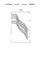
- FIG. 7is a partial plan view of an embodiment of a terminating plate having a multi-row arrangement of the discharge openings.
- FIG. 1shows a sectional view of a write head which is essentially composed of a base body 1 and of a terminating plate 3 which upwardly terminates the base body.
- the base body 1includes lateral raised edgings 4 so that an ink chamber 2 is formed.
- the base body 1can, for example, be a plastic or a glass member to whose lateral edgings 4 the terminating plate 3 composed of conductive material, is applied. This can be accomplished for example, in a galvanoplastic structuring technique.
- the base body 1includes a longitudinal web 5 in the center of the ink chamber 2, the height of this longitudinal web 5 being slightly lower than the height of the lateral edging 4.
- the terminating plate 3not only represents an ink-tight covering toward the outside but also forms the drive elements at the same time.
- These drive elementsare fashioned in the form of webs 6 whose spacing, referred to as columns below, is so small that capillary effects arise.
- the inkis thereby prevented from flowing out given a write head which, as known, functions in accord with what is referred to as the under-pressure method.
- the webs 6extend inwardly in the ink chamber 2 arrow-like, or wedge shaped, in the direction toward the longitudinal web 5 where they form a middle part 7.
- the webs 6 and the middle parts 7thus form the conductor loops.
- Each middle part 7includes a breach 8 which represents the discharge opening.
- the middle parts 7do not lie directly on the surface of the longitudinal web 5 in the idle condition.
- the webs 6here are fashioned at the one side of the ink chamber 2 as mutually insulated and, thus, comprise individually driveable webs.
- the webs 6are connected to one another at the other side of the ink chamber, i.e. they emanate from the terminating plate 3.
- the supply of the ink chamber 2ensues via a supply system (not shown here) which, for example, is connected to one side of the write head at both sides of the longitudinal web 5 via a feed opening.
- the structure of the write headis augmented by a magnet system which, in the example of FIG. 1, is composed of two permanent magnet members 9 and 10 whose north poles N lie opposite one another. It is advantageous when the two pole faces lying opposite one another are spaced at an interval from one another in which a soft iron part 11 is situated.
- the two magnet members 9 and 10are situated below the base body 1 and extend over the full length of the write head.
- a compass of soft iron partscan be provided for improving the concentration of the magnetic field.
- This embodimentis shown in FIG. 1.
- Two soft iron parts 12 and 13 thereinencompass the magnet members 9 and 10 as well as the base plate 1 and extend further into the upper part of the write head.
- the manner of functioning of the arrangement of the inventionis as follows.
- the inkis situated in the inside of the ink chamber 2 at both sides of the longitudinal web 5 under slight static under pressure. As known, this can be achieved in that an ink container (not shown) is located at a lower level than the write head.
- the ink in the ink chamber 2also fills the breaches of discharge openings 8.
- a change in the current flowing through the conductor loopoccurs in a conductor loop 6, 7, this being achieved, for example, by switching the current on, then the webs 6 of the conductor loop lying in the field of the magnet system 9, 10 have a force exerted on them which very rapidly moves the middle part 7 down. This movement is limited by impact against the surface of the longitudinal web 5.
- the mass inertia of the ink quantity contained in the discharge opening 8thereby leads to the ejection of the droplet which is ejected opposite the direction of movement of the middle part.
- the middle part 7 thereuponre-assumes its idle position, whereby the discharge opening 8 is again filled with ink and the quantity of ink used is replenished by suction from the ink reservoir.
- FIG. 2shows the base body 1 and terminating plate 3 in a plan view.
- the terminating plate 3is constructed on the base body 1 and seals the latter and, thus, the ink chamber of the write head toward the outside. At the same time, however, it also represents the drive element unit with the conductor loops. Emanating from the lateral edgings 4, the webs 6 thereof extend inwardly into the ink chamber 2 arrow -like and form the movable middle parts 7 there with the discharge openings 8. The movable middle parts 7 lie above the longitudinal web 5 of the base body 1.
- the ink chamberis connected to an ink supply via feed openings 14. The seal of the write head by means of the terminating plate 3 is guaranteed because the columns 15 between the individual webs 6 are capillary columns.
- the surface of the terminating plate 3is, so to speak, self-cleaning since small quantitites of ink or of ink droplets which proceed to the terminated plate are suctioned back into the ink chamber due to the static under-pressure of the ink as soon as they enter into fluid contact with the ink in a column.
- these advantagesare obtainable with column widths of about 20 ⁇ m.
- the arrangement of the inventionsucceeds in creating extremely small discharge openings, this being advantageous because the ratio of ink quantity in the discharge opening to the ink in the lateral annular gap around the nozzle becomes more unfavorable with increasing length of a discharge opening and the ejection of droplets which always have the same volume and the same speed is made more difficult. Also achieved therewith is that the allocation of discharge openings to drive elements already arises during formation of the drive elements and need not be subsequently achieved by means of involved adjustment or assembly. It is also significant that the cross-talk between neighboring discharge openings is very noticeably reduced, since the stop face of the drive elements is limited to a very narrow region around the discharge openings.
- This reduction of cross-talkcan be promoted in accord with a further embodiment of the invention in that the movable middle parts 7 of the conductor loops rest against the surface of the longitudinal webs in their idle condition. In this case, the movable middle parts are moved out of this idle position, i.e. are moved up, upon a drive executed in the described fashion. In the following return motion into the idle position toward and against the longitudinal web 5, the small quantity of ink contained in the discharge opening is hurled away opposite the motion of the middle part as a consequence of the mass inertia of this quantity of ink and is ejected as an individual droplet.
- the surface of the drive elementis matched to the surface of the stop face.
- This matchingcan ensue in a particularly advantageous way in that the drive elements are galvanoplastically constructed on the stop face.
- a further improvementderives in that a closed cavity 16 is provided in the region around the discharge opening 8 when the middle part 7 rests on the longitudinal web 5.
- a closed cavity 16is provided in the region around the discharge opening 8 when the middle part 7 rests on the longitudinal web 5.
- the cavity 16is formed by a depression in the longitudinal web 5, i.e. in the stop face.
- the cavity 16is formed by an expansion of the discharge opening 8, i.e. is formed in the middle part 7.
- the cavity 16has an oblong shape in either embodiment as shown in FIG. 3 or 4, so that a structure having very narrow middle parts is also possible in this case.
- the movment of the middle part of a conductor loop necessary for the ejection of dropletsis essentially effected by a force which acts on the legs or webs of the conductor loops.
- the course of the field linescomprises two apexes which have a maximum at both sides of the middle parts.
- a magnet system arrangementcan be employed with which what is referred to as an unapexed magnetic field is generated, with which, thus, a field line maximum is reached in the region of the middle parts.
- FIG. 6shows an exemplary embodiment of this development.
- the basic structurecorresponds to the structure which has already been set forth, this being made clear by employing the same reference characters.
- the magnet systemherein is composed of two magnet members 17 and 18 situated below the base body 1, whereby opposite pole faces N or S lie against the base body 1.
- the magnet system 17, 18is covered by a soft iron part 19.
- the interconnectsagain executed in the form of webs 20 lie stretched over the ink chamber 2. They thereby describe an angle of less than 90° with the direction of the longitudinal web 5. This is also true of the part of the web 20 in the region of the longitudinal web 5, i.e. for that part in which the discharge opening 8 is situated.
- the webs 20can be angled off at one side or at both sides in the proximity of their fastening to the base body 1.
- the manner of functioning of the arrangement of FIG. 6essentially corresponds to the manner of functioning already set forth, i.e. a change in current flux in one of the webs 20 exerts a force on the web under the influence of the magnetic field which leads to a movement of the middle part and effects the ejection of a droplet from the discharge opening 8 in the fashion already set forth.
- a maximum of the magnetic field strengthis formed above the contacting line of the two magnet members 17, 18, i.e. the maximum of the magnetic field lines penetrates the webs 20 very close in the region of the discharge openings 8.
- the forcewhich elicits a movement of the middle parts 7 of the webs 20, thus attacks immediately in the region of the discharge openings 8 in this case.
- FIG. 7shows an example of this.
- the conductor loopsare formed on the illustrated terminating plate 21 by the webs 20, whereby the middle parts 7 of the neighboring webs 20 form two rows in the region of the longitudinal web (not shown here).
- the middle part 7 of a web 20 which comprises the discharge opening 8is thereby broadened.
- the discharge openings 8mutually offset, being likewise arranged in two rows.
Landscapes
- Particle Formation And Scattering Control In Inkjet Printers (AREA)
Abstract
Description
Claims (11)
Applications Claiming Priority (2)
| Application Number | Priority Date | Filing Date | Title |
|---|---|---|---|
| DE3500985 | 1985-01-14 | ||
| DE19853500985DE3500985A1 (en) | 1985-01-14 | 1985-01-14 | ARRANGEMENT FOR PRODUCING SINGLE DROPLES IN INK WRITING DEVICES |
Publications (1)
| Publication Number | Publication Date |
|---|---|
| US4620201Atrue US4620201A (en) | 1986-10-28 |
Family
ID=6259786
Family Applications (1)
| Application Number | Title | Priority Date | Filing Date |
|---|---|---|---|
| US06/815,922Expired - LifetimeUS4620201A (en) | 1985-01-14 | 1986-01-03 | Magnetic driver ink jet |
Country Status (3)
| Country | Link |
|---|---|
| US (1) | US4620201A (en) |
| JP (1) | JPS61163865A (en) |
| DE (1) | DE3500985A1 (en) |
Cited By (34)
| Publication number | Priority date | Publication date | Assignee | Title |
|---|---|---|---|---|
| EP0276053A1 (en)* | 1987-01-07 | 1988-07-27 | Domino Printing Sciences Plc | Ink jet printing head |
| WO1993001404A1 (en)* | 1991-07-08 | 1993-01-21 | Yehuda Ivri | Ultrasonic fluid ejector |
| EP0888888A2 (en) | 1997-06-05 | 1999-01-07 | Xerox Corporation | A magnetically actuated ink jet printing device |
| US5938117A (en)* | 1991-04-24 | 1999-08-17 | Aerogen, Inc. | Methods and apparatus for dispensing liquids as an atomized spray |
| US6014970A (en)* | 1998-06-11 | 2000-01-18 | Aerogen, Inc. | Methods and apparatus for storing chemical compounds in a portable inhaler |
| US6205999B1 (en) | 1995-04-05 | 2001-03-27 | Aerogen, Inc. | Methods and apparatus for storing chemical compounds in a portable inhaler |
| US6235177B1 (en) | 1999-09-09 | 2001-05-22 | Aerogen, Inc. | Method for the construction of an aperture plate for dispensing liquid droplets |
| US6467476B1 (en) | 1995-04-05 | 2002-10-22 | Aerogen, Inc. | Liquid dispensing apparatus and methods |
| US6543443B1 (en) | 2000-07-12 | 2003-04-08 | Aerogen, Inc. | Methods and devices for nebulizing fluids |
| US6546927B2 (en) | 2001-03-13 | 2003-04-15 | Aerogen, Inc. | Methods and apparatus for controlling piezoelectric vibration |
| US6550472B2 (en) | 2001-03-16 | 2003-04-22 | Aerogen, Inc. | Devices and methods for nebulizing fluids using flow directors |
| US6554201B2 (en) | 2001-05-02 | 2003-04-29 | Aerogen, Inc. | Insert molded aerosol generator and methods |
| US6629646B1 (en) | 1991-04-24 | 2003-10-07 | Aerogen, Inc. | Droplet ejector with oscillating tapered aperture |
| US6732944B2 (en) | 2001-05-02 | 2004-05-11 | Aerogen, Inc. | Base isolated nebulizing device and methods |
| US6782886B2 (en) | 1995-04-05 | 2004-08-31 | Aerogen, Inc. | Metering pumps for an aerosolizer |
| US6948491B2 (en) | 2001-03-20 | 2005-09-27 | Aerogen, Inc. | Convertible fluid feed system with comformable reservoir and methods |
| US7032590B2 (en) | 2001-03-20 | 2006-04-25 | Aerogen, Inc. | Fluid filled ampoules and methods for their use in aerosolizers |
| US7040549B2 (en) | 1991-04-24 | 2006-05-09 | Aerogen, Inc. | Systems and methods for controlling fluid feed to an aerosol generator |
| US7201167B2 (en) | 2004-04-20 | 2007-04-10 | Aerogen, Inc. | Method and composition for the treatment of lung surfactant deficiency or dysfunction |
| US20070092660A1 (en)* | 2005-10-17 | 2007-04-26 | Samsung Electro-Mechanics Co., Ltd. | Method and device for forming wiring |
| US7290541B2 (en) | 2004-04-20 | 2007-11-06 | Aerogen, Inc. | Aerosol delivery apparatus and method for pressure-assisted breathing systems |
| US7322349B2 (en) | 2000-05-05 | 2008-01-29 | Aerogen, Inc. | Apparatus and methods for the delivery of medicaments to the respiratory system |
| US7331339B2 (en) | 2000-05-05 | 2008-02-19 | Aerogen, Inc. | Methods and systems for operating an aerosol generator |
| US7360536B2 (en) | 2002-01-07 | 2008-04-22 | Aerogen, Inc. | Devices and methods for nebulizing fluids for inhalation |
| US7600511B2 (en) | 2001-11-01 | 2009-10-13 | Novartis Pharma Ag | Apparatus and methods for delivery of medicament to a respiratory system |
| US7628339B2 (en) | 1991-04-24 | 2009-12-08 | Novartis Pharma Ag | Systems and methods for controlling fluid feed to an aerosol generator |
| US7677467B2 (en) | 2002-01-07 | 2010-03-16 | Novartis Pharma Ag | Methods and devices for aerosolizing medicament |
| US7771642B2 (en) | 2002-05-20 | 2010-08-10 | Novartis Ag | Methods of making an apparatus for providing aerosol for medical treatment |
| US7946291B2 (en) | 2004-04-20 | 2011-05-24 | Novartis Ag | Ventilation systems and methods employing aerosol generators |
| US7971588B2 (en) | 2000-05-05 | 2011-07-05 | Novartis Ag | Methods and systems for operating an aerosol generator |
| US8336545B2 (en) | 2000-05-05 | 2012-12-25 | Novartis Pharma Ag | Methods and systems for operating an aerosol generator |
| US8561604B2 (en) | 1995-04-05 | 2013-10-22 | Novartis Ag | Liquid dispensing apparatus and methods |
| US8616195B2 (en) | 2003-07-18 | 2013-12-31 | Novartis Ag | Nebuliser for the production of aerosolized medication |
| US9108211B2 (en) | 2005-05-25 | 2015-08-18 | Nektar Therapeutics | Vibration systems and methods |
Citations (2)
| Publication number | Priority date | Publication date | Assignee | Title |
|---|---|---|---|---|
| US4442443A (en)* | 1982-06-18 | 1984-04-10 | Exxon Research And Engineering Co. | Apparatus and method to eject ink droplets on demand |
| US4546361A (en)* | 1982-10-26 | 1985-10-08 | Ing. C. Olivetti & C., S.P.A. | Ink jet printing method and device |
- 1985
- 1985-01-14DEDE19853500985patent/DE3500985A1/ennot_activeWithdrawn
- 1986
- 1986-01-03USUS06/815,922patent/US4620201A/ennot_activeExpired - Lifetime
- 1986-01-14JPJP61004400Apatent/JPS61163865A/enactivePending
Patent Citations (2)
| Publication number | Priority date | Publication date | Assignee | Title |
|---|---|---|---|---|
| US4442443A (en)* | 1982-06-18 | 1984-04-10 | Exxon Research And Engineering Co. | Apparatus and method to eject ink droplets on demand |
| US4546361A (en)* | 1982-10-26 | 1985-10-08 | Ing. C. Olivetti & C., S.P.A. | Ink jet printing method and device |
Cited By (55)
| Publication number | Priority date | Publication date | Assignee | Title |
|---|---|---|---|---|
| EP0276053A1 (en)* | 1987-01-07 | 1988-07-27 | Domino Printing Sciences Plc | Ink jet printing head |
| US7108197B2 (en)* | 1991-04-24 | 2006-09-19 | Aerogen, Inc. | Droplet ejector with oscillating tapered aperture |
| US7628339B2 (en) | 1991-04-24 | 2009-12-08 | Novartis Pharma Ag | Systems and methods for controlling fluid feed to an aerosol generator |
| US5938117A (en)* | 1991-04-24 | 1999-08-17 | Aerogen, Inc. | Methods and apparatus for dispensing liquids as an atomized spray |
| US20050279851A1 (en)* | 1991-04-24 | 2005-12-22 | Aerogen, Inc. | Method and apparatus for dispensing liquids as an atomized spray |
| US20050263608A1 (en)* | 1991-04-24 | 2005-12-01 | Aerogen, Inc. | Droplet ejector with oscillating tapered aperture |
| US7083112B2 (en) | 1991-04-24 | 2006-08-01 | Aerogen, Inc. | Method and apparatus for dispensing liquids as an atomized spray |
| US6540153B1 (en) | 1991-04-24 | 2003-04-01 | Aerogen, Inc. | Methods and apparatus for dispensing liquids as an atomized spray |
| US6926208B2 (en) | 1991-04-24 | 2005-08-09 | Aerogen, Inc. | Droplet ejector with oscillating tapered aperture |
| US6629646B1 (en) | 1991-04-24 | 2003-10-07 | Aerogen, Inc. | Droplet ejector with oscillating tapered aperture |
| US7040549B2 (en) | 1991-04-24 | 2006-05-09 | Aerogen, Inc. | Systems and methods for controlling fluid feed to an aerosol generator |
| US20070075161A1 (en)* | 1991-04-24 | 2007-04-05 | Aerogen, Inc. | Droplet Ejector With Oscillating Tapered Aperture |
| WO1993001404A1 (en)* | 1991-07-08 | 1993-01-21 | Yehuda Ivri | Ultrasonic fluid ejector |
| US7174888B2 (en) | 1995-04-05 | 2007-02-13 | Aerogen, Inc. | Liquid dispensing apparatus and methods |
| US6640804B2 (en) | 1995-04-05 | 2003-11-04 | Aerogen, Inc. | Liquid dispensing apparatus and methods |
| US6755189B2 (en) | 1995-04-05 | 2004-06-29 | Aerogen, Inc. | Methods and apparatus for storing chemical compounds in a portable inhaler |
| US6782886B2 (en) | 1995-04-05 | 2004-08-31 | Aerogen, Inc. | Metering pumps for an aerosolizer |
| US8561604B2 (en) | 1995-04-05 | 2013-10-22 | Novartis Ag | Liquid dispensing apparatus and methods |
| US6467476B1 (en) | 1995-04-05 | 2002-10-22 | Aerogen, Inc. | Liquid dispensing apparatus and methods |
| US6205999B1 (en) | 1995-04-05 | 2001-03-27 | Aerogen, Inc. | Methods and apparatus for storing chemical compounds in a portable inhaler |
| EP0888888A2 (en) | 1997-06-05 | 1999-01-07 | Xerox Corporation | A magnetically actuated ink jet printing device |
| US8578931B2 (en) | 1998-06-11 | 2013-11-12 | Novartis Ag | Methods and apparatus for storing chemical compounds in a portable inhaler |
| US6014970A (en)* | 1998-06-11 | 2000-01-18 | Aerogen, Inc. | Methods and apparatus for storing chemical compounds in a portable inhaler |
| US7066398B2 (en) | 1999-09-09 | 2006-06-27 | Aerogen, Inc. | Aperture plate and methods for its construction and use |
| US6235177B1 (en) | 1999-09-09 | 2001-05-22 | Aerogen, Inc. | Method for the construction of an aperture plate for dispensing liquid droplets |
| US8398001B2 (en) | 1999-09-09 | 2013-03-19 | Novartis Ag | Aperture plate and methods for its construction and use |
| US7322349B2 (en) | 2000-05-05 | 2008-01-29 | Aerogen, Inc. | Apparatus and methods for the delivery of medicaments to the respiratory system |
| US8336545B2 (en) | 2000-05-05 | 2012-12-25 | Novartis Pharma Ag | Methods and systems for operating an aerosol generator |
| US7971588B2 (en) | 2000-05-05 | 2011-07-05 | Novartis Ag | Methods and systems for operating an aerosol generator |
| US7748377B2 (en) | 2000-05-05 | 2010-07-06 | Novartis Ag | Methods and systems for operating an aerosol generator |
| US7331339B2 (en) | 2000-05-05 | 2008-02-19 | Aerogen, Inc. | Methods and systems for operating an aerosol generator |
| US6543443B1 (en) | 2000-07-12 | 2003-04-08 | Aerogen, Inc. | Methods and devices for nebulizing fluids |
| US6546927B2 (en) | 2001-03-13 | 2003-04-15 | Aerogen, Inc. | Methods and apparatus for controlling piezoelectric vibration |
| US6550472B2 (en) | 2001-03-16 | 2003-04-22 | Aerogen, Inc. | Devices and methods for nebulizing fluids using flow directors |
| US7195011B2 (en) | 2001-03-20 | 2007-03-27 | Aerogen, Inc. | Convertible fluid feed system with comformable reservoir and methods |
| US6948491B2 (en) | 2001-03-20 | 2005-09-27 | Aerogen, Inc. | Convertible fluid feed system with comformable reservoir and methods |
| US7100600B2 (en) | 2001-03-20 | 2006-09-05 | Aerogen, Inc. | Fluid filled ampoules and methods for their use in aerosolizers |
| US7032590B2 (en) | 2001-03-20 | 2006-04-25 | Aerogen, Inc. | Fluid filled ampoules and methods for their use in aerosolizers |
| US8196573B2 (en) | 2001-03-20 | 2012-06-12 | Novartis Ag | Methods and systems for operating an aerosol generator |
| US6732944B2 (en) | 2001-05-02 | 2004-05-11 | Aerogen, Inc. | Base isolated nebulizing device and methods |
| US6978941B2 (en) | 2001-05-02 | 2005-12-27 | Aerogen, Inc. | Base isolated nebulizing device and methods |
| US7104463B2 (en) | 2001-05-02 | 2006-09-12 | Aerogen, Inc. | Base isolated nebulizing device and methods |
| US6554201B2 (en) | 2001-05-02 | 2003-04-29 | Aerogen, Inc. | Insert molded aerosol generator and methods |
| US7600511B2 (en) | 2001-11-01 | 2009-10-13 | Novartis Pharma Ag | Apparatus and methods for delivery of medicament to a respiratory system |
| US8539944B2 (en) | 2002-01-07 | 2013-09-24 | Novartis Ag | Devices and methods for nebulizing fluids for inhalation |
| US7677467B2 (en) | 2002-01-07 | 2010-03-16 | Novartis Pharma Ag | Methods and devices for aerosolizing medicament |
| US7360536B2 (en) | 2002-01-07 | 2008-04-22 | Aerogen, Inc. | Devices and methods for nebulizing fluids for inhalation |
| US7771642B2 (en) | 2002-05-20 | 2010-08-10 | Novartis Ag | Methods of making an apparatus for providing aerosol for medical treatment |
| US8616195B2 (en) | 2003-07-18 | 2013-12-31 | Novartis Ag | Nebuliser for the production of aerosolized medication |
| US7946291B2 (en) | 2004-04-20 | 2011-05-24 | Novartis Ag | Ventilation systems and methods employing aerosol generators |
| US7201167B2 (en) | 2004-04-20 | 2007-04-10 | Aerogen, Inc. | Method and composition for the treatment of lung surfactant deficiency or dysfunction |
| US7267121B2 (en) | 2004-04-20 | 2007-09-11 | Aerogen, Inc. | Aerosol delivery apparatus and method for pressure-assisted breathing systems |
| US7290541B2 (en) | 2004-04-20 | 2007-11-06 | Aerogen, Inc. | Aerosol delivery apparatus and method for pressure-assisted breathing systems |
| US9108211B2 (en) | 2005-05-25 | 2015-08-18 | Nektar Therapeutics | Vibration systems and methods |
| US20070092660A1 (en)* | 2005-10-17 | 2007-04-26 | Samsung Electro-Mechanics Co., Ltd. | Method and device for forming wiring |
Also Published As
| Publication number | Publication date |
|---|---|
| DE3500985A1 (en) | 1986-07-17 |
| JPS61163865A (en) | 1986-07-24 |
Similar Documents
| Publication | Publication Date | Title |
|---|---|---|
| US4620201A (en) | Magnetic driver ink jet | |
| US5519424A (en) | Ink jet print head | |
| US4544933A (en) | Apparatus and method for ink droplet ejection for a printer | |
| US4842493A (en) | Piezoelectric pump | |
| KR100554807B1 (en) | Method and apparatus for ink chamber evacuation | |
| US4641153A (en) | Notched piezo-electric transducer for an ink jet device | |
| US5940096A (en) | Ink jet printhead assembly with non-emitting orifices | |
| US4514743A (en) | Ink jet filtered-chamber print head | |
| US4376284A (en) | Ink jet print head | |
| US20030085959A1 (en) | Compact printhead and method of delivering ink to the printhead | |
| KR101056321B1 (en) | Droplet ejection device | |
| US7296879B2 (en) | Liquid ejection head and method of producing the same | |
| DE19813470B4 (en) | Inkjet printhead | |
| US4376944A (en) | Ink jet print head with tilting nozzle | |
| US20020041301A1 (en) | Ink-jet printer head | |
| US7681995B2 (en) | Liquid ejection head and method of manufacturing the same | |
| JPS5923275B2 (en) | Multi-nozzle liquid particle generator | |
| JPS5840508B2 (en) | Impulse type multi-nozzle inkjet head | |
| US5801734A (en) | Two row flat face charging for high resolution printing | |
| US3786516A (en) | Deflection electrode device for an ink jet printing apparatus | |
| EP0844088A2 (en) | Electrostatic ink-jet printing head and method for manufacturing the same | |
| JPS58124661A (en) | Ink jet recorder | |
| EP0847859B1 (en) | Electrostatic ink-jet printing head | |
| JPS5911255A (en) | Inkjet head | |
| JPS6467351A (en) | Ink jet head |
Legal Events
| Date | Code | Title | Description |
|---|---|---|---|
| AS | Assignment | Owner name:SIEMENS AKTIENGESELLSCHAFT, MUNICH AND BERLIN, GER Free format text:ASSIGNMENT OF ASSIGNORS INTEREST.;ASSIGNORS:HEINZL, JOACHIM;PENNINGSFELD, HANS-DIETER;BERDELLE-HILGE, PETER;REEL/FRAME:004503/0005 Effective date:19851203 | |
| STCF | Information on status: patent grant | Free format text:PATENTED CASE | |
| FEPP | Fee payment procedure | Free format text:PAYOR NUMBER ASSIGNED (ORIGINAL EVENT CODE: ASPN); ENTITY STATUS OF PATENT OWNER: LARGE ENTITY | |
| FPAY | Fee payment | Year of fee payment:4 | |
| FPAY | Fee payment | Year of fee payment:8 | |
| AS | Assignment | Owner name:INKJET SYSTEMS GMBH & CO. KG, GERMANY Free format text:ASSIGNMENT OF ASSIGNORS INTEREST;ASSIGNOR:EASTMAN KODAK COMPANY;REEL/FRAME:007201/0578 Effective date:19940926 | |
| AS | Assignment | Owner name:EASTMAN KODAK COMPANY, NEW YORK Free format text:CORRECTION OF RECORDATION OF ASSIGNMENT RECORDED AT REEL 7201, FRAMES 578-605;ASSIGNOR:INKJET SYSTEMS GMBH 7 CO.KG;REEL/FRAME:007512/0687 Effective date:19940926 | |
| FEPP | Fee payment procedure | Free format text:PAYER NUMBER DE-ASSIGNED (ORIGINAL EVENT CODE: RMPN); ENTITY STATUS OF PATENT OWNER: LARGE ENTITY Free format text:PAYOR NUMBER ASSIGNED (ORIGINAL EVENT CODE: ASPN); ENTITY STATUS OF PATENT OWNER: LARGE ENTITY | |
| FPAY | Fee payment | Year of fee payment:12 |