US4618132A - Rear window light screen particularly for an automobile - Google Patents
Rear window light screen particularly for an automobileDownload PDFInfo
- Publication number
- US4618132A US4618132AUS06/613,739US61373984AUS4618132AUS 4618132 AUS4618132 AUS 4618132AUS 61373984 AUS61373984 AUS 61373984AUS 4618132 AUS4618132 AUS 4618132A
- Authority
- US
- United States
- Prior art keywords
- light
- vanes
- rotating
- admitting
- blocking
- Prior art date
- Legal status (The legal status is an assumption and is not a legal conclusion. Google has not performed a legal analysis and makes no representation as to the accuracy of the status listed.)
- Expired - Fee Related
Links
- 230000000903blocking effectEffects0.000claimsdescription17
- 230000004044responseEffects0.000claimsdescription9
- 238000001514detection methodMethods0.000claimsdescription7
- 230000007246mechanismEffects0.000claimsdescription4
- 230000008878couplingEffects0.000claims2
- 238000010168coupling processMethods0.000claims2
- 238000005859coupling reactionMethods0.000claims2
- 230000009467reductionEffects0.000description4
- 230000005540biological transmissionEffects0.000description3
- 238000010276constructionMethods0.000description2
- 238000003780insertionMethods0.000description2
- 230000037431insertionEffects0.000description2
- 230000004075alterationEffects0.000description1
- 230000000694effectsEffects0.000description1
- 230000004048modificationEffects0.000description1
- 238000012986modificationMethods0.000description1
Images
Classifications
- B—PERFORMING OPERATIONS; TRANSPORTING
- B60—VEHICLES IN GENERAL
- B60J—WINDOWS, WINDSCREENS, NON-FIXED ROOFS, DOORS, OR SIMILAR DEVICES FOR VEHICLES; REMOVABLE EXTERNAL PROTECTIVE COVERINGS SPECIALLY ADAPTED FOR VEHICLES
- B60J1/00—Windows; Windscreens; Accessories therefor
- B60J1/20—Accessories, e.g. wind deflectors, blinds
- B60J1/2011—Blinds; curtains or screens reducing heat or light intensity
- B60J1/2088—Lamellar or like blinds
Definitions
- the present inventionrelates to a rear window light screen or blind, particularly for an automobile, which automatically functions to prevent direct rays of sun from passing through the rear window of an automobile when the vehicle is stopped or parked but allows an unobstructed view through the rear window during operation of the car.
- Another object of the present inventionis to provide a light screen in the rear window of an automobile which will not impede vision through the rear window during operation of the vehicle.
- Still another object of the present inventionis a light screen for use in the rear window of an automobile which is only deployed in the absence of operation of or an operation in the automobile.
- a light screen devicefor selectively blocking light from entering the rear window of an automobile comprising a plurality of vanes, means for rotating the vanes between a light blocking position and a light admitting position, means for generating a vehicle operation signal, and means for controlling the rotating means to rotate the vanes to the light blocking position responsive to the vehicle operation signal indicating non-operation of the vehicle and to the light admitting position responsive to the vehicle operation signal indicating operation of the vehicle.
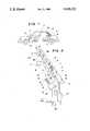
- FIG. 1schematically illustrates an automobile including the light screen device of the present invention.
- FIG. 2illustrates the mechanism of the light screen device of the present invention.
- An automobile 1includes an ignition switch 2 which is electrically associated by a drive mechanism 3 with a light screen device 4.
- the ignition switch 2may be replaced by a seat sensor switch 2A mounted in or on a seat.
- a key 5is adopted for insertion into the ignition switch 2.
- a stationary arm member 6,constitutes a part of the rear light screen 4 and includes a plurality of stationary pins 8, 8A, 8B . . . on which screen vanes 7, 7A, 7B . . . are pivotally supported.
- Meansare provided for rotating the vanes 7, 7A, 7B . . . between a light blocking position and a light admitting position.
- this meanscomprises connector pins 9, 9A, 9B . . . connected to respective screen vanes 7, 7A, 7B . . . at their base ends and to an actuator lever 10.
- the blind vanes 7, 7A, 7B . . .are angularly moved around the respective stationary pins 8, 8A, 8B . . . in a direction as indicated by an arrow C or an arrow D, as the actuator lever 10 is moved in a direction as indicated by an arrow A or an arrow B, respectively.
- the rotating meansfurther includes a pin 11 on the actuator lever 10 at a portion of its length in a loose engagement with a notch 13 of a fork-like drive arm 12.
- the drive arm 12is mounted on a gear 14 at a base end of the arm 12 at 15 so that the drive arm 12 is angularly moved in a direction as indicated by an arrow E or an arrow F as the gear 14 is angularly moved counterclockwise or clockwise, respectively.
- the rotating meansfurther includes a reduction gear system including gears 16, 17 and a transmission gear 18 directly coupled to an electric motor 19, serving as a drive means, on one side, and engaged with the reduction gear system 17, on the other side.
- a reduction gear systemincluding gears 16, 17 and a transmission gear 18 directly coupled to an electric motor 19, serving as a drive means, on one side, and engaged with the reduction gear system 17, on the other side.
- Rotation of the electric motor 19causes angular movement of the arm 12 in the direction of the arrow E or F via the transmission gear 18, the reduction gear system 17, 16 and the gear 14.
- a position detection change-over switch 20includes a contact 21 which is normally biased against the drive arm 12.
- the change-over switch 20is adapted to detect an angular position of the drive arm 12, in other words, whether the blind vanes 7, 7A, 7B . . are opened or shut. The output of the switch 20 is changed depending on the detected position.
- the controlling meanscomprises an electronic control circuit 22 connected to the position detection change-over switch 20 so that, in response to a signal coming from the position detection switch 20, the electronic control circuit 22 applies input terminals 23, 24, of the electric motor 19 with components +, -, or -, 130 , respectively.
- both the ignition switch 2 and the seat sensor switch 2Aare in ON-state while the car 1 is operating, the seat sensor switch 2A being in this state because then a driver is sitting on the seat, so that the power components +, -, are supplied via the electronic control circuit 22 to the input terminals 22, 24, respectively, rotating the motor 19 forwards, to open the blind vanes 7, 7A, 7B . . .
- the light screen devicefurther includes means for generating a vehicle operation signal.
- the generating meanscomprises the ignition switch 2 or the seat sensor 2a.
- an OFF signal from the switch 2 or 2A and an "open screen vanes" signal from the position detection change-over switch 20cause the electronic control circuit 22 to apply the input terminals 23, 24 of the motor 19 with the power components -, +, respectively, to rotate the motor 19 in reverse.
- Reference numeral 25designates a DC power source.
- the electronic control circuit 22is applied with an ON signal from the switch 2 and the signal from the position detection change-over switch 20. Under these circumstances, the terminals 23, 24 of the motor 29 are supplied with the components +, -, respectively.
- the motor 19is rotated in the forward direction and angularly moves the drive arm 12 through the transmission gear 18, the reduction gear system 17, 16 and the gear 14 in the direction as indicated by the arrow E.
- the actuator lever 10is driven through the fork-like portion or notch 13 and the pin 11 moves in the direction indicated by the arrow A.
- Such movement of the actuator lever 10 in the direction of the arrow Acauses the connector pins 9, 9A, 9B . . . to rotate the blind vanes 7, 7A, 7B . . .
- the blind vanes 7, 7A, 7B . . .are maintained open, since the ignition switch 2 is kept in ON-state.
- the OFF signal from the switch 2 and the signal from the position detection change-over switch 20cause the electronic control circuit 22 to supply the input terminals 23, 24 of the motor with the power components -, +, respectively.
- the motor 19is rotated in reverse to shut the blind vanes 7, 7A, 7B . . .
- the screen vanesare automatically maintained open to assure the unobstructed rear view as long as the car is running.
- the blind vanesare reliably shut, however, to intercept the sunlight whenever the car is stopped or parked, i.e., is not in operation.
Landscapes
- Engineering & Computer Science (AREA)
- Mechanical Engineering (AREA)
- Specific Sealing Or Ventilating Devices For Doors And Windows (AREA)
- Window Of Vehicle (AREA)
Abstract
Description
Claims (8)
Applications Claiming Priority (2)
| Application Number | Priority Date | Filing Date | Title |
|---|---|---|---|
| JP1983083789UJPS59187513U (en) | 1983-05-31 | 1983-05-31 | Rear blind device for automobiles, etc. |
| JP58-83789[U] | 1983-05-31 |
Publications (1)
| Publication Number | Publication Date |
|---|---|
| US4618132Atrue US4618132A (en) | 1986-10-21 |
Family
ID=13812407
Family Applications (1)
| Application Number | Title | Priority Date | Filing Date |
|---|---|---|---|
| US06/613,739Expired - Fee RelatedUS4618132A (en) | 1983-05-31 | 1984-05-24 | Rear window light screen particularly for an automobile |
Country Status (2)
| Country | Link |
|---|---|
| US (1) | US4618132A (en) |
| JP (1) | JPS59187513U (en) |
Cited By (9)
| Publication number | Priority date | Publication date | Assignee | Title |
|---|---|---|---|---|
| US5634682A (en)* | 1995-11-07 | 1997-06-03 | Young; Hai T. | Sunshine shelter apparatus for window area of passenger transportation |
| WO1998039171A1 (en)* | 1997-03-05 | 1998-09-11 | Hai Tee Young | Sunshine shelter apparatus for window area of passenger transportation |
| US5884731A (en)* | 1997-02-05 | 1999-03-23 | Young; Hai Tee | Extensible sunshine shelter apparatus for window area of passenger transportation |
| WO1999041480A3 (en)* | 1998-02-17 | 1999-10-28 | Tristeck Ltd | Roll-up shutter |
| US6095230A (en)* | 1998-06-15 | 2000-08-01 | Quaker State Investment Corporation | Vehicle sun shades |
| US6135191A (en)* | 1998-09-08 | 2000-10-24 | Quaker State Investment Corporation | Collapsible vehicle sun shade |
| US20080295408A1 (en)* | 2007-05-31 | 2008-12-04 | Brose Schliesssysteme Gmbh & Co. Kg | Method for Motorized Movement of a Motor Vehicle Door |
| US20110068601A1 (en)* | 2009-09-23 | 2011-03-24 | Gm Global Technology Operations, Inc. | Vehicle Solar Load Reduction System |
| US20140059931A1 (en)* | 2012-09-05 | 2014-03-06 | Leonid J. Tasheiko | Variable window shutter systems and methods |
Citations (14)
| Publication number | Priority date | Publication date | Assignee | Title |
|---|---|---|---|---|
| US2279011A (en)* | 1938-07-07 | 1942-04-07 | Nicholson Joseph | Switch operating mechanism |
| US2565979A (en)* | 1947-09-26 | 1951-08-28 | Harry P Michaelsen | Remotely controlled venetian blind for auto rear windows |
| US2574729A (en)* | 1949-07-15 | 1951-11-13 | Clifford C Coffman | Remote-control blind operator for motor vehicles |
| US2607906A (en)* | 1948-12-06 | 1952-08-19 | Victor S Sang | Automatic glare shield control |
| US2657923A (en)* | 1951-08-27 | 1953-11-03 | John R Andre | Automobile venetian blind and control means therefor |
| US3343868A (en)* | 1966-02-11 | 1967-09-26 | Jr Arman K Manookian | Automatic visors for automotive vehicles or the like |
| US3770313A (en)* | 1970-06-02 | 1973-11-06 | N Jimenez | Automotive auxiliary windshield |
| US3894206A (en)* | 1971-12-18 | 1975-07-08 | Tokai Rika Co Ltd | Pressure responsive switch |
| US4042918A (en)* | 1976-05-04 | 1977-08-16 | Klitzman Charles B | Apparatus indicating an absent golf club |
| US4242672A (en)* | 1977-11-09 | 1980-12-30 | Gault Robert L | Patient monitoring system and switch |
| US4250486A (en)* | 1979-03-19 | 1981-02-10 | Deere & Company | Vehicle motion alarm |
| US4360801A (en)* | 1980-04-14 | 1982-11-23 | Stanley Vemco | Home security and garage door operator system |
| FR2525971A1 (en)* | 1982-05-03 | 1983-11-04 | Mauras Mecanique Gle | Angle positioning mechanism for motor vehicle louvre blinds - uses micromotor controlled by driver to rotate shaft carrying louvre blade coupling linkage |
| US4497515A (en)* | 1983-03-28 | 1985-02-05 | Appelson Jay M | Stake-out curtains for automobiles |
Family Cites Families (1)
| Publication number | Priority date | Publication date | Assignee | Title |
|---|---|---|---|---|
| JPS5846650B2 (en)* | 1979-07-13 | 1983-10-18 | 三恵技研工業株式会社 | hollow multi-tube |
- 1983
- 1983-05-31JPJP1983083789Upatent/JPS59187513U/enactivePending
- 1984
- 1984-05-24USUS06/613,739patent/US4618132A/ennot_activeExpired - Fee Related
Patent Citations (14)
| Publication number | Priority date | Publication date | Assignee | Title |
|---|---|---|---|---|
| US2279011A (en)* | 1938-07-07 | 1942-04-07 | Nicholson Joseph | Switch operating mechanism |
| US2565979A (en)* | 1947-09-26 | 1951-08-28 | Harry P Michaelsen | Remotely controlled venetian blind for auto rear windows |
| US2607906A (en)* | 1948-12-06 | 1952-08-19 | Victor S Sang | Automatic glare shield control |
| US2574729A (en)* | 1949-07-15 | 1951-11-13 | Clifford C Coffman | Remote-control blind operator for motor vehicles |
| US2657923A (en)* | 1951-08-27 | 1953-11-03 | John R Andre | Automobile venetian blind and control means therefor |
| US3343868A (en)* | 1966-02-11 | 1967-09-26 | Jr Arman K Manookian | Automatic visors for automotive vehicles or the like |
| US3770313A (en)* | 1970-06-02 | 1973-11-06 | N Jimenez | Automotive auxiliary windshield |
| US3894206A (en)* | 1971-12-18 | 1975-07-08 | Tokai Rika Co Ltd | Pressure responsive switch |
| US4042918A (en)* | 1976-05-04 | 1977-08-16 | Klitzman Charles B | Apparatus indicating an absent golf club |
| US4242672A (en)* | 1977-11-09 | 1980-12-30 | Gault Robert L | Patient monitoring system and switch |
| US4250486A (en)* | 1979-03-19 | 1981-02-10 | Deere & Company | Vehicle motion alarm |
| US4360801A (en)* | 1980-04-14 | 1982-11-23 | Stanley Vemco | Home security and garage door operator system |
| FR2525971A1 (en)* | 1982-05-03 | 1983-11-04 | Mauras Mecanique Gle | Angle positioning mechanism for motor vehicle louvre blinds - uses micromotor controlled by driver to rotate shaft carrying louvre blade coupling linkage |
| US4497515A (en)* | 1983-03-28 | 1985-02-05 | Appelson Jay M | Stake-out curtains for automobiles |
Cited By (12)
| Publication number | Priority date | Publication date | Assignee | Title |
|---|---|---|---|---|
| US5634682A (en)* | 1995-11-07 | 1997-06-03 | Young; Hai T. | Sunshine shelter apparatus for window area of passenger transportation |
| US5884731A (en)* | 1997-02-05 | 1999-03-23 | Young; Hai Tee | Extensible sunshine shelter apparatus for window area of passenger transportation |
| WO1998039171A1 (en)* | 1997-03-05 | 1998-09-11 | Hai Tee Young | Sunshine shelter apparatus for window area of passenger transportation |
| WO1999041480A3 (en)* | 1998-02-17 | 1999-10-28 | Tristeck Ltd | Roll-up shutter |
| US6453972B1 (en) | 1998-02-17 | 2002-09-24 | Tristeck Ltd. | Roll-up shutter |
| US6095230A (en)* | 1998-06-15 | 2000-08-01 | Quaker State Investment Corporation | Vehicle sun shades |
| US6135191A (en)* | 1998-09-08 | 2000-10-24 | Quaker State Investment Corporation | Collapsible vehicle sun shade |
| US20080295408A1 (en)* | 2007-05-31 | 2008-12-04 | Brose Schliesssysteme Gmbh & Co. Kg | Method for Motorized Movement of a Motor Vehicle Door |
| US9217271B2 (en)* | 2007-05-31 | 2015-12-22 | Brose Schliesssysteme Gmbh & Co. Kg | Method for motorized movement of a motor vehicle door |
| US20110068601A1 (en)* | 2009-09-23 | 2011-03-24 | Gm Global Technology Operations, Inc. | Vehicle Solar Load Reduction System |
| CN102019839A (en)* | 2009-09-23 | 2011-04-20 | 通用汽车环球科技运作公司 | Vehicle solar load reduction system |
| US20140059931A1 (en)* | 2012-09-05 | 2014-03-06 | Leonid J. Tasheiko | Variable window shutter systems and methods |
Also Published As
| Publication number | Publication date |
|---|---|
| JPS59187513U (en) | 1984-12-12 |
Similar Documents
| Publication | Publication Date | Title |
|---|---|---|
| US4618132A (en) | Rear window light screen particularly for an automobile | |
| US6125983A (en) | Electric parking sprag | |
| JPH10138762A (en) | Automatic opening and closing device for pop-up type door | |
| US3154168A (en) | Automobile engine time delay stop safety control | |
| JP2687601B2 (en) | Spoiler device for automobile | |
| JPS5923727A (en) | Safety device for sun roof of automobile | |
| KR19980032933U (en) | Solar Sun Detection Sun Visor | |
| KR100341302B1 (en) | The angle control apparatus of sun visor for vehicle | |
| KR200313244Y1 (en) | Automatic window closing device at start-off in the car | |
| KR0167952B1 (en) | Room mirror auto rotator | |
| JPS5820546A (en) | Wiper device for fender mirror | |
| KR0126982Y1 (en) | Automatic blind device of car rear windshield | |
| KR900009003B1 (en) | Vehicles rear spolier usable for a back mirror | |
| KR960004741Y1 (en) | Inside mirror angle adjuster of car | |
| JP2000052885A (en) | On-vehicle display device | |
| KR100223247B1 (en) | Vehicle side mirror protection | |
| KR100199581B1 (en) | Adjustable rearview mirror | |
| KR200200844Y1 (en) | The car automatic control unit side-mirror | |
| JP2717961B2 (en) | Vehicle sliding door structure | |
| KR19980047198U (en) | Switchgear of car sunroof | |
| KR19980041461U (en) | Self-folding side mirror for pressure detection of vehicle | |
| GB2435919A (en) | Vehicle lamp assembly with variable illuminating direction | |
| KR0149645B1 (en) | Outside mirror revolution device of an automobile | |
| KR0130458Y1 (en) | Betting mode changer of car | |
| KR19980024407U (en) | Anti-glare device of car room mirror |
Legal Events
| Date | Code | Title | Description |
|---|---|---|---|
| AS | Assignment | Owner name:HONDA GIKEN KOGYO KABUSHIKI KAISHA,JAPAN Free format text:ASSIGNMENT OF ASSIGNORS INTEREST;ASSIGNORS:KIMURA, RYOICHI;NOMURA, KANJI;UBUKATA, KAZUMI;AND OTHERS;SIGNING DATES FROM 19840511 TO 19840516;REEL/FRAME:004265/0347 Owner name:JECO KABUSHIKI KAISHA,JAPAN Free format text:ASSIGNMENT OF ASSIGNORS INTEREST;ASSIGNORS:KIMURA, RYOICHI;NOMURA, KANJI;UBUKATA, KAZUMI;AND OTHERS;SIGNING DATES FROM 19840511 TO 19840516;REEL/FRAME:004265/0347 Owner name:JECO KABUSHIKI KAISHA, 790 TAKATUKU KUJI KAWASAKI- Free format text:ASSIGNMENT OF ASSIGNORS INTEREST.;ASSIGNORS:KIMURA, RYOICHI;NOMURA, KANJI;UBUKATA, KAZUMI;AND OTHERS;REEL/FRAME:004265/0347;SIGNING DATES FROM 19840511 TO 19840516 Owner name:HONDA GIKEN KOGYO KABUSHIKI KAISHA, 27-8, JINGUMAE Free format text:ASSIGNMENT OF ASSIGNORS INTEREST.;ASSIGNORS:KIMURA, RYOICHI;NOMURA, KANJI;UBUKATA, KAZUMI;AND OTHERS;REEL/FRAME:004265/0347;SIGNING DATES FROM 19840511 TO 19840516 | |
| CC | Certificate of correction | ||
| FEPP | Fee payment procedure | Free format text:PAYOR NUMBER ASSIGNED (ORIGINAL EVENT CODE: ASPN); ENTITY STATUS OF PATENT OWNER: LARGE ENTITY | |
| FPAY | Fee payment | Year of fee payment:4 | |
| REMI | Maintenance fee reminder mailed | ||
| LAPS | Lapse for failure to pay maintenance fees | ||
| FP | Lapsed due to failure to pay maintenance fee | Effective date:19941026 | |
| STCH | Information on status: patent discontinuation | Free format text:PATENT EXPIRED DUE TO NONPAYMENT OF MAINTENANCE FEES UNDER 37 CFR 1.362 |