US4617927A - Electrosurgical unit - Google Patents
Electrosurgical unitDownload PDFInfo
- Publication number
- US4617927A US4617927AUS06/584,959US58495984AUS4617927AUS 4617927 AUS4617927 AUS 4617927AUS 58495984 AUS58495984 AUS 58495984AUS 4617927 AUS4617927 AUS 4617927A
- Authority
- US
- United States
- Prior art keywords
- voltage
- output
- power
- input
- microprocessor
- Prior art date
- Legal status (The legal status is an assumption and is not a legal conclusion. Google has not performed a legal analysis and makes no representation as to the accuracy of the status listed.)
- Expired - Lifetime
Links
- 239000004065semiconductorSubstances0.000claimsdescription22
- 230000005669field effectEffects0.000claimsdescription7
- 230000004044responseEffects0.000claimsdescription3
- 230000015271coagulationEffects0.000abstractdescription15
- 238000005345coagulationMethods0.000abstractdescription15
- 239000000203mixtureSubstances0.000abstractdescription15
- 239000003990capacitorSubstances0.000description57
- 238000004804windingMethods0.000description30
- 239000000872bufferSubstances0.000description23
- 238000013461designMethods0.000description19
- 230000001276controlling effectEffects0.000description9
- 230000000694effectsEffects0.000description9
- 230000006870functionEffects0.000description7
- 230000001105regulatory effectEffects0.000description7
- 238000010586diagramMethods0.000description6
- 230000009471actionEffects0.000description5
- 230000003321amplificationEffects0.000description5
- 239000013078crystalSubstances0.000description5
- 230000009977dual effectEffects0.000description5
- 230000001965increasing effectEffects0.000description5
- 238000000034methodMethods0.000description5
- 238000003199nucleic acid amplification methodMethods0.000description5
- 238000012360testing methodMethods0.000description5
- 238000012546transferMethods0.000description5
- 230000003287optical effectEffects0.000description4
- 239000007787solidSubstances0.000description4
- 230000008901benefitEffects0.000description3
- 230000033228biological regulationEffects0.000description3
- 238000010276constructionMethods0.000description3
- 238000001514detection methodMethods0.000description3
- 230000036316preloadEffects0.000description3
- 230000000630rising effectEffects0.000description3
- 230000001225therapeutic effectEffects0.000description3
- 229910001369BrassInorganic materials0.000description2
- 239000004677NylonSubstances0.000description2
- 235000014676Phragmites communisNutrition0.000description2
- 240000007320Pinus strobusSpecies0.000description2
- 239000010951brassSubstances0.000description2
- 238000006243chemical reactionMethods0.000description2
- 230000008878couplingEffects0.000description2
- 238000010168coupling processMethods0.000description2
- 238000005859coupling reactionMethods0.000description2
- 230000007423decreaseEffects0.000description2
- 238000002955isolationMethods0.000description2
- 229920001778nylonPolymers0.000description2
- 230000008569processEffects0.000description2
- 238000012545processingMethods0.000description2
- 230000009467reductionEffects0.000description2
- 229920006395saturated elastomerPolymers0.000description2
- 239000000758substrateSubstances0.000description2
- 238000001356surgical procedureMethods0.000description2
- 230000001360synchronised effectEffects0.000description2
- 238000013024troubleshootingMethods0.000description2
- 229910000859α-FeInorganic materials0.000description2
- 239000004831Hot glueSubstances0.000description1
- 230000004913activationEffects0.000description1
- 238000013459approachMethods0.000description1
- 230000009286beneficial effectEffects0.000description1
- 210000004204blood vesselAnatomy0.000description1
- 230000015556catabolic processEffects0.000description1
- 230000008859changeEffects0.000description1
- 239000004020conductorSubstances0.000description1
- 230000007547defectEffects0.000description1
- 230000001419dependent effectEffects0.000description1
- 238000003745diagnosisMethods0.000description1
- 230000036541healthEffects0.000description1
- 230000017525heat dissipationEffects0.000description1
- 230000020169heat generationEffects0.000description1
- 238000010438heat treatmentMethods0.000description1
- 230000001939inductive effectEffects0.000description1
- 230000002401inhibitory effectEffects0.000description1
- 230000007257malfunctionEffects0.000description1
- 238000004519manufacturing processMethods0.000description1
- 238000012986modificationMethods0.000description1
- 230000004048modificationEffects0.000description1
- 238000012544monitoring processMethods0.000description1
- 230000004043responsivenessEffects0.000description1
- 230000001052transient effectEffects0.000description1
- 238000009423ventilationMethods0.000description1
- 238000012795verificationMethods0.000description1
- 125000000391vinyl groupChemical group[H]C([*])=C([H])[H]0.000description1
- 229920002554vinyl polymerPolymers0.000description1
- 230000000007visual effectEffects0.000description1
Images


Classifications
- A—HUMAN NECESSITIES
- A61—MEDICAL OR VETERINARY SCIENCE; HYGIENE
- A61B—DIAGNOSIS; SURGERY; IDENTIFICATION
- A61B18/00—Surgical instruments, devices or methods for transferring non-mechanical forms of energy to or from the body
- A61B18/04—Surgical instruments, devices or methods for transferring non-mechanical forms of energy to or from the body by heating
- A61B18/12—Surgical instruments, devices or methods for transferring non-mechanical forms of energy to or from the body by heating by passing a current through the tissue to be heated, e.g. high-frequency current
- A61B18/1206—Generators therefor
- A—HUMAN NECESSITIES
- A61—MEDICAL OR VETERINARY SCIENCE; HYGIENE
- A61B—DIAGNOSIS; SURGERY; IDENTIFICATION
- A61B18/00—Surgical instruments, devices or methods for transferring non-mechanical forms of energy to or from the body
- A61B18/04—Surgical instruments, devices or methods for transferring non-mechanical forms of energy to or from the body by heating
- A61B18/12—Surgical instruments, devices or methods for transferring non-mechanical forms of energy to or from the body by heating by passing a current through the tissue to be heated, e.g. high-frequency current
- A61B18/1206—Generators therefor
- A61B18/1233—Generators therefor with circuits for assuring patient safety
- A—HUMAN NECESSITIES
- A61—MEDICAL OR VETERINARY SCIENCE; HYGIENE
- A61B—DIAGNOSIS; SURGERY; IDENTIFICATION
- A61B18/00—Surgical instruments, devices or methods for transferring non-mechanical forms of energy to or from the body
- A61B2018/00636—Sensing and controlling the application of energy
- A61B2018/0066—Sensing and controlling the application of energy without feedback, i.e. open loop control
- A—HUMAN NECESSITIES
- A61—MEDICAL OR VETERINARY SCIENCE; HYGIENE
- A61B—DIAGNOSIS; SURGERY; IDENTIFICATION
- A61B18/00—Surgical instruments, devices or methods for transferring non-mechanical forms of energy to or from the body
- A61B18/04—Surgical instruments, devices or methods for transferring non-mechanical forms of energy to or from the body by heating
- A61B18/12—Surgical instruments, devices or methods for transferring non-mechanical forms of energy to or from the body by heating by passing a current through the tissue to be heated, e.g. high-frequency current
- A61B18/14—Probes or electrodes therefor
- A61B2018/1472—Probes or electrodes therefor for use with liquid electrolyte, e.g. virtual electrodes
Definitions
- the inventionin general relates to electrosurgery and in particular to an electrosurgical unit utilizing solid state electronics.
- Electrosurgical generatorswhich produce high frequency electric currents used for cutting of tissue and coagulation of small blood vessels have been well-known for at least fifty years.
- cascode configurationin which one electrical component provides a current gain while another component provides a voltage gain has been known in the electronics field for at least a generation.
- a cascode configurationconsisting of a bipolar transistor and a field effect transistor (FET) connected in series, called a hybrid cascode configuration, has been known for many years. See, for example, United Kingdom Patent Application GB No. 2 053 606 A published Feb. 4, 1981, and the cascode configuration shown on page 6 of the Modern Electronic Circuits Reference Manual by John Markus, (McGraw Hill 1980).
- Such a use of the semiconductor devicenecessarily requires that the device be used in instances when it is not in saturation, in which cases the devices are highly inefficient. Those skilled in the art have believed that this would lead to high power dissipation in an electrosurgical unit with the resultant inefficiency, unreliability, and/or the necessity for ventilating fans which exhaust non-sterile air into the operating room environment.
- the inventionprovides an electrosurgical unit comprising a direct current power source, a means for amplifying connected to the power source comprising: first and second semiconductor devices each having an input and an output, and a control terminal for controlling the electrical flow through the device, the semiconductor devices being connected with their outputs in series with one another and in series and with the load of said amplifier; a first voltage control means for applying a control voltage to the control terminal of the first semiconductor device, the first voltage control means including a means for varying the control voltage over a range corresponding to at least a plurality of conducting states of the first semiconductor device; and a second voltage control means for applying a control voltage to the control terminal of the second semiconductor device; and a means for electrically connecting the means for amplifying to electrosurgical electrodes.
- the first voltage control meanscomprises a means for applying a DC or low frequency signal and the second voltage control means comprises a means for applying a high frequency signal.
- the inventionin one embodiment includes a means for applying a varying voltage to the control terminal of the first semiconductor device for controlling the power of the electrosurgical unit, and the second voltage control means comprises a means for applying a signal of fixed duty cycle.
- the second voltage control meansmay also comprise a means for applying a signal of variable duty cycle for controlling the power of the electrosurgical unit.
- the first semiconductor deviceis a bipolar transistor and the second semiconductor device is a field effect transistor.
- the inventioncomprises an electrosurgical unit comprising a direct current power source, a means for amplifying connected to the power source, the means comprising: a bipolar transistor connected in series with a field effect transistor; a first voltage control means for applying a control voltage to the base of the bipolar transistor; and a second voltage control means for applying a control voltage to the gate of the field effect transistor; and also comprises a means for electrically connecting the means for amplifying to electrosurgical electrodes.
- the means for electrically connecting the amplifier and the electrodes in an electrosurgical unitcomprises a transformer having primary and secondary windings that are wound concentrically about the same axis and are spaced from each other along the axis.
- a first portion of the secondary windingis wound at one end of the primary and a second portion of the secondary is wound at the opposite end of the primary.
- the inventionprovides an electrosurgical unit capable of providing the cut, coagulation, blend and fulguration radio frequency modes with a single, simple amplification circuit.
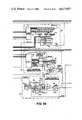
- FIGS. 1A through 1Care a block diagrammatic illustration of a preferred embodiment of the invention; the full electrosurgical unit may be seen by placing FIG. 1A on the left, FIG. 1B in the center and FIG. 1C on the right, in which positions the interconnections between the Figs. are evident;
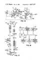
- FIG. 2shows an electrical circuit diagram of the basic hybrid cascode amplifier according to the invention
- FIG. 3is detailed electrical schematic of the hybrid cascode power amplifier of the preferred embodiment of the invention shown in FIG. 1C;
- FIG. 4is a detailed electrical schematic of the output stage of the embodiment of the invention shown in FIG. 1C;
- FIG. 5shows the core of the bipolar transformer utilized in the embodiment of FIG. 4;
- FIG. 6illustrates the method of winding the primary winding on the core of FIG. 5;
- FIG. 7shows the method of winding of the secondary winding on the core of FIG. 5;
- FIG. 8is a partial sectional view of the monopolar transformer utilied in the embodiment of FIG. 4;
- FIG. 9is an external view of the transformer of FIG. 8;
- FIG. 10is a partial sectional end view of the transformer of FIG. 9;
- FIG. 11is a detailed electrical schematic of a portion of the Power Supply of the embodiment of the invention in FIG. 1A;
- FIG. 12is the power-on reset circuitry of the embodiment of the invention shown in FIG. 1A;
- FIG. 13is a detailed electrical schematic of the lamp/relay register of the embodiment of the circuitry shown in FIG. 1A;
- FIG. 14is a detailed electrical schematic of the Gate Waveform Generator/Driver of the embodiment of the invention shown in FIG. 1B;
- FIG. 15 and FIG. 16show a detailed electrical schematic of the Base Voltage Generator/Driver of the embodiment of the invention shown in FIG. 1B.
- FIG. 17is a detailed electrical schematic showing the connections to the microprocessor in the embodiment of the invention shown in FIG. 1A;
- FIG. 18is a block diagram of the microprocessor.
- FIG. 19is a diagram showing the waveform generator counter states at specified times of the counter cycle.
- FIGS. 1A through 1Can electrosurgical unit according to the preferred embodiment of the invention is shown.
- the blocks shownare divided along functional boundaries.
- the schematic diagrams in the following Figs.are divided along the same functional lines where possible. Connections across physical boundaries are shown where they apply.
- the Cut and Coagulation mode settingsare activated via the handswitches and the footswitches 10 which are conventional in electrosurgical units and will not be described further herein.
- a power amplifier 23comprising a first semiconductor device 24 and a second semiconductor device 25 provides the electrical power to the outputs 22 through output circuitry 30.
- a first voltage control means 34comprising Base Voltage Generator/Driver (FIG. 1B) applies a control voltage to control terminal 27 of first semiconductor device 24, and a second voltage control means 33 comprising Gate Waveform Generator/Driver 33 applies a control voltage to control terminal 28 of second semiconductor device 25.
- Outputs 22are conventional electrosurgical connectors for the particular electrodes indicated, and comprise a means for electrically connecting the output circuitry 30 and the means for amplifying 23 to electrosurgical electrodes.
- the power for the electrosurgical unitis provided by Power Supply (source) 36 (FIG. 1A).
- the Power Supply 36converts the AC mains power to the various DC supply voltages required by the circuitry.
- switches 10 and 10c, potentiometers 14 and multiplexer 54comprise a means for producing a predetermined first digital signal representative of a desired characteristic of the unit.
- a portion of power supply 36(shown in FIG. 11) comprises a means for producing a second digital signal representative of an operating characteristic of the electrosurgical unit.
- the Controller 20embodies the intelligence of the unit. It responds to user commands, communicates with the user via displays and tones, directs and supervises the activities of all other modules in the system, performs fault detection and aids in diagnosis.
- the Controller 20includes a memory 50a (FIG. 18) which is a means for storing the signal representative of a desired characteristic of the unit.
- the Display 37provides the user with visual indications of current power settings for each mode, Pure/Blend mode selection, Bipolar Hi/Lo mode selection, which mode is currently activated and indication of fault conditions requiring the user's attention.
- the Gate Waveform Generator/Driver 33produces the FET gate 28 drive signals for the power amplifier under control of the microprocessor 50. It includes circuitry 80 for producing a signal (COAG-Q) which is utilized to suppress the voltage limitation effect (see below) when the system is in Coagulation mode.
- COAG-Qa signal which is utilized to suppress the voltage limitation effect (see below) when the system is in Coagulation mode.
- the Base Voltage Generator/Driver (BVG) 34supplies base current to the power amplifier bipolar transistors 24 at a voltage appropriate to the mode of operation. It includes circuitry 92, 95, 111 for limiting the voltage at the outputs 22.
- the WFG 33 and the portions of the Controller 20 other than memory 51acomprise a means responsive to a first digital signal and a second digital signal for controlling an output means of the electrosurgical unit.
- the BVG 34 and the portions of the Controller 20 other than the memory 50acomprise such a means for controlling an output means.
- the Power Amp (PA) 25responds to its input signals in a fashion necessary to produce therapeutically useful RF currents.
- the RF Output circuitry 30transfers the RF power generated by the power amplifier 23 to the output connector panel.
- the display 37comprises an information output means of the unit.
- the Power Amp 25 and the output circuitry 30comprise a therapeutic output means of the electrosurgical unit.
- the Continuity Detector 39delivers to the microprocessor 50 the status of various contacts (not shown) in the isolated RF output circuit.
- the contactsare those of the conventional hand-switchable bipolar and active monopolar accessories and the two wire patient plate circuit, which are connected to outputs 22.
- Power Supply 36is connected to an AC outlet by power plug 40.
- the unitis turned on or off via switch 41 between power plug 40 and isolation power transformer 42.
- Power Supply 36converts the AC outlet power to the various DC supply voltages required by the unit.
- the nominal supply valuesare shown at the right of power supply 36 in FIG. 1A, and include two switched power supplies 43 and 44 which enhance the safety of the unit.
- Controller 20includes microprocessor 50, the timing for which is provided by a crystal oscillator 51.
- a signal from the 12 volt unregulated output of power supply 36is applied to the microprocessor 50 at input AN1.
- Controller 20further includes multiplexer 54 which multiplexes and feeds the signals from controls 10 and 14 to microprocessor 50.
- Controller 20also includes multiplexer register 57, audio generator 58, expander-decoder 60, lamp/relay register 61 and associated buffers 62 and 63, power on reset circuitry 64 and watchdog timer 65.
- a signal, ISENSEis supplied to multiplexer 54 from power supply 36 which is representative of the current drawn from the 120 volt power supply output. This is calibrated by current sense resistor 45.
- Control signals for the multiplexer 54are provided from the microprocessor 50 and expander-decoder 60 outputs via multiplexer register 57.
- Audio generator 58is controlled via outputs from microprocessor 50 and expander-decoder 60 to produce a signal to drive speaker 59.
- the volume of the audio generator 58is controlled via volume control 66 and a loud/soft signal generated by microprocessor 50.
- Expander-decoder 60receives output signals from microprocessor 50 which are demultiplexed by expander-decoder 60 using synchronization signals /PROG and ALE which are also provided to expander-decoder 60 by microprocessor 50.
- the output signals of expander-decoder 60are provided to multiplexer register 57, audio generator 58, the decoder/driver 70 of the display circuitry 37 (FIG. 1B) the Gate Waveform Generator register 80, the watchdog timer 65 and the lamp/relay register 61.
- the lamp/relay register 61receives output signals from microprocessor 50, expander-decoder 60, and power-on reset circuitry 64 and in turn applies output signals to display circuitry 37 (FIG. 1B) and output circuitry 30 (FIG. 1C) via buffers 62 and 63 respectively.
- the power-on reset circuitryapplies signals to the lamp relay register 61, the microprocessor 50, and the watchdog timer 65.
- the watchdog timer 65uses its own internal timing signals and the inputs from expander-decoder 60 and power-on reset 64 to provide control signals to power relay switches 43 and 44 and microprocessor 50.
- the microprocessor 50also receives input signals from continuity detector 39 (FIG. 1C) and applies control signals to gate driver 88 and base voltage multiplexer 95 (FIG. 1B).
- the Display circuitry 37includes decoder/driver 70, seven segment LED display 71, mode indicators 72, 73 and 74, alarm indicators 75, 76, and 77, inverter 78, and resistor 79.
- the signals from the microprocessor 50 and expander-decoder 60are decoded by the decoder/driver 70 which in turn drives display 71.
- Signals from the lamp/relay register 61drive mode indicator 72, 73, and 74 and alarm indicator 75 and 76.
- a signal from the detector 109is also applied to the plate alarm indicator 76 via inverter 78 and resistor 79.
- a signal from the watchdog timer 65drives machine alarm indicator 77.
- the Gate Waveform Generator/Driver circuitryincludes waveform generator register 80, 18 MHz oscillator 81, waveform generator counter 84, offtime decoder 85, blend counter 86, and gate driver 88.
- the waveform generator register 80receives inputs from microprocessor 50, expander-decoder 60, and waveform generator counter 84 and applies control signals to waveform generator counter 84, OFFTIME decoder 85, base voltage multiplexer 95 and blend counter 86.
- the waveform generator counter 84receives a timing signal from oscillator 81, the preloaded ONTIME signal from waveform generator register 80, and a signal from OFFTIME decoder 85 and in turn provides signals to waveform generator register 80, OFFTIME decoder 85, blend counter 86 and gate driver 88.
- the blend counterreceives the above-indicated signals and applies a signal to the OFFTIME decoder 85 which in turn applies a signal to waveform generator counter 84 in response to the signals previously described.
- the signals from the waveform generator counter 84 and the microprocessor 50control the gate driver 88 to produce the gate drive output signal which is applied to the gate of the field effect transistors 25 in the Power Amplifier 23.
- Base Voltage Generator/Driver 34comprises feed forward gain compensator 90, cut power calibration potentiometer 91, cut reference voltage amplifier 92, coag drive voltage divider 93 comprising resistors 93a and 93b, cut drive voltage potentiometer 94, base voltage multiplexer 95, operational amplifier 97, and base driver amp 98.
- a voltage signal produced by potentiometer 91is applied to feed forward gain compensator 90 which in turn applies a voltage to cut reference amplifier 92.
- Other inputs to cut reference amplifier 92are the +5 reference voltage and a voltage signal, VCOLL from the output voltage sense circuitry 111 in output stage 30 (FIG. 1C).
- Resistor 93ais connected between voltage divider 93 and the +15 power supply while resistor 93b is connected between the ground and the voltage divider.
- the output of cut reference operational amplifier 92is applied to the base voltage multiplexer 95 through potentiometer 94 which is controlled by cut power control 99.
- the other side of potentiometer 94 and the base voltage multiplexer 95are connected to ground.
- the control signals for the base voltage multiplexer 95are provided by outputs of gate waveform generator register 80 and microprocessor 50.
- the output of base voltage multiplexer 95is applied to the non-inverting input of operational amplifier 97, while the inverting input is connected via a voltage divider (FIG. 15) to the output of base driver 98.
- the output of operational amplifier 97is applied to the input of base driver 98 and the +15 volt RF power supply is also applied to base driver 98.
- the output of base driver 98is applied to the base of the bipolar transistors 24 in power amp 23.
- Continuity Detector 39comprises 100 KHz oscillator/driver 100, toroidal transformer 101, isolated power supplies 102, emitters 103, and detectors 106.
- the oscillator driver 100drives the primary circuit of transformer 101, the secondaries of which in turn drive isolated power supplies 102.
- the outputs of the power supplies 102are applied to the emitters 103 which are also connected to the switches (not shown) for the hand, foot, plate, and bipolar electrodes through connectors 22.
- the light from the emitters 103is detected by detectors 106.
- Detector 109which is associated with the emitter which is connected to the plate electrode is applied to the plate alarm indicator 76 as indicated above, and also to the microprocessor 50.
- the outputs of detectors 106are applied to microprocessor 50.
- Output stage 30comprises output relays 110 (which include switches 115 and 116), output voltage sense circuitry 111, monopolar transformer 112 which includes a sense winding 113, bipolar transformer 114, and four capacitors such as 118a.
- the inputs to the output relaysare from the lamp/relay register 61 (FIG. 1A) and the 24 volt relay output voltage.
- the physical connection between the output relays and the switches 115 and 116is shown by a dotted line.
- One side of both monopolar and bipolar transformers 112 and 114is connected to the +120 volt unregulated power supply while the other side is connected to Power Amp 23 through switch 115.
- One side of sense winding 113is connected to ground while the other side is applied to output voltage sense circuitry 111.
- One side of secondary 208 of monopolar transformer 112is connected to the outputs 124, 125, and 126 for the hand and foot controlled monopolar electrodes through switches 116 and capacitor 118a. The other side is connected to ground through the leakage cancellation circuitry 117 and to the plate electrode output 123 through capacitor 118b.
- One side of the secondary 209 of bipolar transformer 114is connected to one of the terminals of bipolar output 122 through capacitor 119a while the other side is connected to another of the terminals of bipolar output 122 through capacitor 119b.
- the Power Amplifier circuitry 23has already been discussed above and will be discussed in considerably more detail below.
- FIG. 2shows a simplified embodiment of the basic hybrid cascode amplifier of the present invention.
- the simplified circuitry of FIG. 2will be useful in understanding the preferred embodiment of the hybrid cascode amplifier which is shown in FIG. 3.
- the FET device 25 and the bipolar device 24a diode 130 and the electrosurgical unit load 131 (which is the amplifier load) are connected in series between ground and the +120 volts power supply. More particularly, the source terminal 25a of the FET 25 is connected to ground while the drain 25b of the FET 25 is connected to the emitter 24a of the bipolar transistor 24.
- the collector 24b of the bipolar transistor 24is connected to the cathode of the diode 130 while the anode of the diode is connected to one side of the load 131.
- the other side of the loadis connected to the positive voltage supply.
- the control terminal or gate 28 of FET 25is connected to a voltage source 134 designated VGATE which in terms of the preferred embodiment of the present invention is the output signal of the Gate Waveform Generator/Driver circuitry 33 (FIG. 1B).
- the other side of the voltage source 134is connected to ground.
- the control terminal or base 27 of bipolar transistor 24is connected to a voltage source designated as VBASE through resistor 137 which is designated Rb.
- the voltage source 139is the output signal of the Base Voltage Generator/Driver 34.
- the other side of the voltage source 139is connected to ground.
- the base 27 of bipolar device 24is also connected to ground through capacitor 135 designated as Cb. This is a bypass capacitor which stores the turnoff charge of bipolar device 24.
- the hybrid cascode stage of the preferred embodiment of the inventionconsists of two separate hybrid cascode sections connected at the collector bus 144.
- One sectioncomprises FET 146 and bipolar transistors 147, 148, and 149, while the other section comprises FET 152 and bipolar transistors 153, 154, and 155. Since the circuitry associated with each of the FETs is identical, and the circuitry associated with each of the bipolar transistors is identical, the circuitry shall be described for only the FET 146 and the transistor 148.
- the circuitry associated with FET 146comprises zener diode 157 and resistors 158 and 159.
- the cathode of diode 157is connected to the line 160 carrying the incoming gate drive voltage, while its anode is connected to the source, S, of FET 146.
- Resistor 158is connected between the cathode of diode 157 and the gate of FET 146 in the line 160 carrying the gate voltage to the gate.
- Resistor 159is connected between the gate, G, of FET 146 and the anode of diode 157.
- the anode of diode 157 and the source, S, of FET 146are grounded.
- the circuitry associated with transistor 148includes resistor 162, capacitors 163 and 164, fuses 165 and 168, resistor 166, and diode 167.
- Resistor 162is connected between the drain, D, of FET 146 and the emitter, E, of transistor 148.
- Fuse 165is connected along the line 169 carrying the base drive voltage VBASE to the base, B, of transistor 148.
- Resistor 166is also connected along the base voltage input line 169 between fuse 165 and base, B.
- Capacitor 163is connected between line 169 and ground at a point between fuse 165 and resistor 166, while capacitor 164 is connected between base, B, and ground.
- the cathode of diode 167is connected to the collector, C, of transistor 148 while the anode of the diode is connected to one side of fuse 168.
- the other side of fuse 168is connected to the collector bus 144.
- the drain, D, of FET 146is connected to the anode of diode 171 and the cathode of the diode is connected to the 120 volt voltage source through resistor 172.
- Zener diode 173 and capacitor 174are connected in parallel between the cathode of diode 171 and ground, with the anode of diode 173 being connected to the ground side.
- the line 169is connected to ground through a parallel zener diode 176 and capacitor 177, with the anode of diode 176 being toward the ground side.
- the collector bus 144is connected to the output circuit (FIG. 4).
- the collector busis connected to either the monopolar transformer 112 or the bipolar transformer 114 depending upon the position of switch 115.
- Much of the output circuit 30 of FIG. 4has been discussed in reference to FIG. 1c, and thus we shall here discuss only those aspects of the circuit which were not discussed therein.
- the output relay circuitry 110includes relay coils 181, 182, and 183 which act on the corresponding relay contacts 116A through 116C and coil 184 which acts on contact 115.
- the relay coils 181 through 183are connected between the input lines /H1-K, /H2-K, /FT-K respectively, and the +24 relay supply voltage.
- Coil 184is connected between the /BIP-K input line and the +24 relay supply voltage.
- Diode 186is connected in series with the coil 184 along the /BIP-K input line with its anode toward the coil.
- Capacitors, such as 185,are connected between each of the four input lines and ground. The input lines are connected to the corresponding signal lines shown as outputs (TO OUTPUT) in FIG. 13.
- the output voltage sense circuitry 111includes SENSE winding 113, diode 190, capacitors 191, 194, and 195, and resistors 192 and 193.
- the anode of diode 190is connected to one side of the SENSE winding 113, while the cathode is connected to the anode of diode 415 (FIG. 16) through resistor 192.
- the other side of SENSE winding 113is connected to ground.
- Capacitor 191is connected between the cathode of diode 190 and the ground line from the SENSE winding 113.
- Resistance 193 and capacitors 194 and 195are connected in parallel between the VCOLL voltage line and the ground line.
- the transformer primary circuitryincludes resistors 201 and 202 and capacitors 203, 204, and 205. Resistor 201 and capacitor 203 are connected in parallel between the 120 volt supply voltage line and the collector bus line. Resistor 202 is connected between the 120 volt line voltage line and the side of primary 207 to which the collector bus is applied.
- Bipolar transformer 114includes primary 206, secondary 209, and core 210.
- Monopolar transformer 112includes primary 207, secondary 208, and core 211.
- the leakage cancellation circuitry 117includes capacitors 212 and 213, inductance 214, and resistance 215. The four are connected in series, in the order just given, between the side of the monopolar secondary which goes to the patient plate and ground.
- FIGS. 5 through 10The construction of the bipolar transformer 114 is shown in FIGS. 5 through 7.
- the unwrapped core 210is shown in FIG. 5.
- the portion of core 210 which will contact primary 206 and secondary 209,is covered with insulating tape 221.
- FIG. 6shows the winding of the preferred 12 turns of the primary 206 on the core 210.
- FIG. 7shows the winding of the preferred 13 turns of the secondary 209 on the core 210.
- the primary and secondaryare wound concentrically about the same axis, six turns of the secondary 209 are wound at one end 206a of the primary 206, another six turns are wound at the other end 206b, and there is one turn crossing over the primary 206.
- the primaryis covered by a layer of insulating tape 220 in FIG. 7. After the secondary is wound, it is also covered by insulating tape.
- FIGS. 8, 9, and 10show the construction of the monopolar transformer.
- the transformeris built on a nonconductive bobbin 229 which consists of a hollow cylinder 230 having four dividers 231, 232, 233, and 234 attached to its outer surface.
- the shape of the dividersis rectangular on one end and circular on the other as shown best in FIG. 10.
- the primary winding 207is wound between the center dividers 232 and 233 with the ends of the primary 207 passing through holes such as 251 (FIG. 9) in the dividers.
- the secondary winding 208is wound between the dividers 231 and 232 and then passes through holes 253 and 254 in dividers 232 and 233 respectively, crossing the primary winding 207, and is then wound between dividers 233 and 234.
- the primary 207 and secondary 208are wound concentrically and a first portion 208a of the secondary 208 is wound at one end 207a of the primary 207, while a second portion 208b of the secondary 208 is wound at the other end 207b of the primary 207.
- the ends of the secondaryare looped through holes, such as 256, in the dividers 231 and 234.
- Each of the windingsare covered with insulated tape, 235.
- the primary windinghas 71/2 turns of wire with the direction of the winding passing from front to rear at the lower portion of FIG. 8.
- the secondary windinghas 27 turns with 8 turns in the first layer 258, 7 turns in each of the second and third layers and 5 turns in the fourth and outer layer. It is preferably wound in a counter-clockwise direction passing from right to left in FIGS. 8 and 9.
- the core 211 of the monopolar transformerconsists of four cylindrical ferrite core pieces 240, 241, 242, and 243 which fit inside of cylinder 230 of bobbin 229.
- the core pieces 240 through 243have a cylindrical bore passing through their centers.
- Rod 246 having threaded endspasses through the centers of core pieces 240 through 243.
- Nonconductive washers 244 and 245fit over the ends of bobbin cylinder 231 and are held in place by nuts 247 and 248 which are screwed on to the ends of rod 246.
- Hot melt adhesive 233is melted into one end of cylinder 231 to hold the cores 211 firmly in position.
- SENSE winding 113is preferably a single wind about primary 207, preferably at the end of the primary 207 connected to the 120 volt line rather than the end connected to the collector, again wound in the counter-clockwise direction. The ends of SENSE winding 113 are twisted together as shown at 259.
- FIG. 11shows the details of the 12 volt unregulated power supply and the production of a signal, AN1, which is fed into the microprocessor, and used by the microprocessor to regulate the duty cycle of the coagulation and bipolar outputs to produce a uniform output power despite variations of the mains voltage.
- the circuitry of FIG. 11comprises a means for producing a second signal representative of an operating characteristic of the electrosurgical unit. This signal is digitized by the A/D converter 50h (FIG. 18) in the microprocessor as will be discussed below.
- the power supply circuitryincludes AC plug 40, a lighted circuit breaker 41 which includes single pole double throw breaker switch 41a and 41b, resistor 268 and light 267 which indicates the on or off condition of the circuit breaker 41, transformer 42a, bridge rectifier 272, and capacitors 275 through 277.
- the symbol 273indicates that the two wires are a twisted pair.
- Voltage regulator 280 and capacitor 281comprise circuitry to produce the 5-volt regulated power supply.
- the green wire of plug 40is connected to chassis, the white wire is connected to one side of primaries 270a and 270b through circuit breaker 41a, while the black wire is connected to the other side of the primaries through circuit breaker 41b and thermofuse 269.
- the two outputs of the transformer secondary 270care applied across bridge rectifier 272.
- Capacitors 275, 276, 277, and 281are connected in parallel across the outputs of bridge rectifier 272.
- the negative output of rectifier 272is grounded and the positive output provides the 12-volt unregulated power supply.
- the positive output of bridge 272is also applied to the input of voltage regulator 280, while the common line is attached to the negative side of the rectifier 272 which is grounded.
- the output of voltage regulator 280provides the 5-volt regulated power supply.
- the circuitry for providing a signal representative of the unregulated 12-volt power supply, which varies directly as the mains voltage, as a control signal to the microprocessercomprises resistors 284, 286, 290, and 291, capacitors 285, and 292, and potentiometer 287.
- the 12-volt power supplyis applied to one side of resistor 284 and the other side is grounded through capacitor 285 and also connected to resistor 286.
- the other side of resistor 286is connected to one input and the output of potentiometer 287.
- the other input of potentiometer 287is grounded through resistor 290.
- the output of potentiometer 287is applied through resistor 291 to the microprocessor (FIG. 1a) to provide the input signal for power regulation.
- the output line 293is grounded through capacitor 292.
- FIG. 12shows the details of the power-on reset circuitry which insures orderly power up of the electrosurgical unit. It includes capacitor 297, resistor 298, diode 299, three input NAND GATE 300, and inverter 304.
- the three inverted inputs of NAND GATE 300are connected to ground through capacitor 297 and the 5-volt power supply through resistor 298. They are also connected to the 5-volt power supply through diode 299, with the cathode of the diode toward the power supply.
- the output of NAND GATE 300provides the POR signal to microprocessor 50 and is also applied to the input of inverter 304.
- the output of inverter 304provides the /POR signal to the lamp/relay register 61 and the watchdog timer 65.
- FIG. 13shows detailed circuitry of the lamp/relay register 61 and the gate waveform generator register 80, both of which receive the P10 through P17 signals from the microprocessor 50.
- the alphabetic or alphanumeric characters on the incoming lines, such as LMPRLYSTB on the line coming into input 11 of chip 61a or P10 coming into input 17 of the same chip,are the names of the signals that are applied to the lines.
- the alphanumeric characters on the inside of the chip and adjacent to the inputs and outputs, such as the D0 which is opposite the number 17 input of chip 61a,indicate the names of the signals for processing purposes within the chips.
- the numbers of the input and output terminalsare useful for determinig the connections between the chips, while the signal names will be useful in describing the operation of the chips below.
- the lamp relay register 61includes octal buffer 61a and 8 inverters, 7 of which (61b through 61c) are part of an O-C buffer.
- the terminal numbers of the inverterscorrespond to the inputs and outputs of the buffer.
- the /LMBRLYSTB signal from the expander-decoderis applied to the number 11 input of buffer 61a and the P10 through P17 signals from the microprocessor 50, emanating from the 25 through 32 output terminals of the microprocessor, are applied to the 17, 18, 14, 13, 4, 7, 8, and 3 inputs respectively of buffer 61a.
- the /POR signalis applied to the inverted 1 input of buffer 61a.
- the 16, 19, 15, 12, 5, 6, 9, and 2 outputs of buffer 61aare connected to the 2, 1, 3, 4, 7, 6, 5, and 9 inputs respectively of buffer 61b.
- the 15, 16, 14, and 13 outputs of buffer 61bprovide the /BIP-K, /H1-K, /H2-K, and /FT-K signals respectively.
- the connections of these outputs of buffer 61bcan best be seen by following the signals indicated to the output circuitry of FIG. 4 and noting the connections, which were discussed above.
- the 15, 10, and 11 outputs of buffer 61bare connected to the bipolar, coag, and cut lights respectively in the display.
- the 12 output of buffer 61bis applied to the patient plate light in the display, while the output of inverter 61d is applied to the operator light in the display.
- the register 80is included in FIG. 13 in order to more easily note the terminals to which the P10 through P17 signals from the microprocessor 50 are applied, but will be discussed in FIG. 14 where they are shown in more detail.
- the circuitryincludes dual D flip flop 80a, octal buffer 80b, crystal oscillator 81, 4 bit counters 316, 317, 318, and 86, inverter 322, NOR gates 324 and 325, AND/OR inverter 327, inverters 331 and 332, clock drivers 334a and 334b, and resistors 338 and 339.
- the symbol at 340indicates that the two wires associated with the loop are coaxial cable.
- the 10 and 13 inputs of flip flop 80aare connected to the 5-volt power supply.
- the /WFTSTB signal from the expander-decoder 60is applied to the 12 input of flip flop 80a.
- the number 13 output of 4 bit counter 316is connected to the 11 input of flip flop 80a.
- the number 9 output of flip flop 80ais connected to the 11 input of buffer 80b.
- the 18, 17, 14, 13, 8, 7, 4, and 3 inputs of buffer 80bare connected respectively to the 25 through 32 outputs of microprocessor 50.
- the inverted 1 input of buffer 806is connected to the 5-volt power supply.
- the 19, 16, 15, and 12 outputs of buffer 80bare connected to the 3, 4, 5, and 6, inputs respectively of counter 316.
- the 9 and 6 outputs of buffer 80bare connected to the 3 and 4 inputs respectively of counter 317.
- the 5 and 6 inputs of counter 317 and the 3, 4, 5, inputs of counter 318are connected to the 5-volt power supply, while the 6 input of counter 318 is grounded.
- the 2 output of buffer 80bis connected to the 1, 10, and 7 inputs of counter 86.
- the 3 and 4 input of counter 86are grounded while the 5 and 6 inputs are connected to the 5-volt power supply.
- the 14 input of oscillator 81is connected to the 5-volt power supply, while the 7 input is grounded.
- the 8 outputis connected to the 2 inputs of counters 316, 317, and 318.
- the 1 and 10 inputs of counters 316, 317, and 318, and the 7 input of counter 316are all connected to the 5-volt power supply.
- the 7 inputs of counters 317 and 318are connected to the 15 output of counter 316.
- the 9 inputs of counters 316, 317, and 318are connected to the 8 output of AND/OR-invert gate 327.
- the 11 output of counter 316is connected to the 12 input of AND-OR-invert gate 327.
- the 14 and 11 outputs of counter 317are connected to the 11 and 4 inputs respectively of AND-OR-invert gate 327.
- the 15 output of counter 317is connected to the 10 input of counter 318.
- the 13 output of counter 318is connected to the 9 input of AND-OR-invert gate 327.
- the 11 output of counter 318is connected to the 2 input of counter 86, the 9 input of NOR gate 324, and the 1, 6, and 10 inputs of AND-OR-invert gate 327.
- the 6 output of buffer 80bis connected to the 12 input of NOR gate 325 and the input of inverter 322.
- the 15 output of counter 86is connected to the 11 input of NOR gate 325 and 5 input of AND-OR-invert gate 327.
- the 13 output of NOR gate 325is connected to the 9 input of counter 86 and the 13 input of AND-OR-invert gate 327.
- the 2 and 3 inputs of AND-OR-invert gate 327are grounded.
- the output of inverter 322provides the /COAG-Q signal which will be discussed in reference to FIG. 15.
- the /RFENA signal from the 38 output of microprocessor 50is applied to the 8 input of NOR gate 324.
- the 10 output of NOR gate 324is applied to the inputs of inverters 331 and 332.
- the outputs of inverters 331 and 332are applied to the inputs of drivers 334a and 334b respectively.
- the inputs of drivers 334a and 334bare also tied to the +15-volt radiofrequency power supply through resistors 336 and 337 respectively.
- the 3 input of the dual driver 334is connected to ground and the 6 input is connected to the 15-volt radiofrequency power supply.
- the dotted line between the drivers 334a and 334bindicate that both are connected to both the ground and 15-volt power supply.
- the output of driver 334ais applied through resistor 338 to the circuitry of FIG. 3 as the Gate A voltage, while the output of driver 334b is applied through resistor 339 to the circuitry of FIG. 3 to provide the Gate B voltage.
- FIG. 15shows the base voltage multiplexer 95 which includes diodes 352 and 357 (which form an analog OR gate) resistor 358, and FET 360.
- Open Collector driver 350 and inverter 322(FIG. 14) also assist in the multiplexing action.
- the voltage divider circuitry 93includes resistors 93a, 351 and 93b.
- the /COAG-Q signal from the output of inverter 322(FIG. 14) is applied to the input of driver 350.
- the output of driver 350is applied to the anode of diode 352 through resistor 351.
- the line between the output of driver 350 and transistor 351is connected to the 15-volt regulated power supply through resistor 93a, while the line between resistor 351 and diode 352 is connected to ground through resistor 93b.
- the cathode of diode 352is connected to the noninverting input (5 input) of operational amplifier 97.
- the CUTDRV-V voltage(which is supplied by the circuitry of FIG. 16) is fed into the multiplexer through circuitry including resistors 355, 356.
- the CUTDRV-V voltage from the output of potentiometer 94(FIG. 16) is applied to the anode of diode 357 through resistor 356.
- the line between the output of potentiometer 94 and resistor 356is grounded through resistor 355.
- the cathode of diode 357is connected to the 5 input of driver 97 and also to ground through resistor 358.
- the /RFENA signal from the 38 output of microprocessor 50is applied to the gate of FET 360, while the source of the FET is connected to ground and the drain is connected to the line between the cathodes of diodes 357 and 352 and the 5 input of op amp 97.
- the inverting input (6 input) of op amp 97is connected to ground through resistor 365.
- the 4 inputis connected to ground and the 8 input is connected to the 15-volt power supply and to ground through capacitors 363 and 364.
- the 7 output of op amp 97is connected to the base of transistor 375 through resistor 372, to the 15-volt power supply through resistor 371, and to the inverting input through capacitor 370.
- the collector of transistor 375is connected to the +15-volt RF power supply, and to ground through capacitor 374.
- the emitterprovides the VBASE signal that drives the bases of the transistors of FIG. 3.
- the emitter of transistor 375is also connected to the inverting input of op amp 97 through resistor 373 and to ground through capacitor 376.
- the VBASE lineis a coaxial cable the outer conductor of which is grounded.
- the CUTDRV-V voltageis provided by the circuitry of FIG. 16.
- the circuitryincludes a dual potentiometer having knob 99 mounted on the front panel which adjusts potentiometers 15 and 94, potentiometer 91, transistor 380, optical isolator 400, operational amplifier 410, capacitors 381, 382, 391, 416, and 417, and resistors 383, 384, 387, 390, 392, 393, 409, 411, and 419 and diode 415.
- One input of potentiometer 15is connected to ground while the other is connected to the +5 reference voltage through resistor 387.
- the output of potentiometer 15provides the CUTSET-V voltage (FIG. 1A) and is also applied to the base of transistor 380 through resistor 384.
- Capacitor 381is connected between the two inputs to potentiometer 15 while capacitor 382 and resistor 383 are connected in parallel between the grounded input and the output.
- the collector of transistor 380is connected to the 5-volt power supply while the emitter is connected to ground through the incandescent lamp in optical isolator 400.
- One input of potentiometer 91is connected to ground through resistor 393 while the other input is connected to the 12-volt unregulated power supply through resistors 390 and 392.
- the line between resistors 390 and 392is connected to ground through capacitor 391.
- the high input and the output of potentiometer 91are connected to the inverting input (2 input) of operational amplifier 410 through the photoresistor side of optical isolator 400.
- the output voltage derived from SENSE winding 113, VCOLL,is applied to the anode of diode 415 which is also connected to ground through capacitors 416 and 417.
- the cathode of diode 415is applied to the inverting input of operational amplifier 410.
- Capacitor 408 and resistor 409are connected in parallel between the output (1 pin) of operational amplifier 410 and the inverting input.
- the noninverting input (pin 3) of operational amplifier 410is connected to the 5-volt reference power supply through resistor 411.
- the output of operational amplifier 410is applied to one input of potentiometer 94, while the other input of the potentiometer is grounded through resistor 419.
- the output of potentiometer 94provides the CUTDRV-V voltage.
- the dotted line in FIG. 16indicates the physical connection of the two potentiometers 15 and 94.
- FIG. 17shows the microprocessor 50, indicating the connections to the microprocessor that have not already been discussed, and also showing the microprocessor signals associated with the various inputs and outputs of the microprocessor.
- the circuitry directly associated with the microprocessor and not previously discussed in detailincludes 3.579 mHz crystal 51, capacitors 426, 429, 433, 434, and 439, and resistors 427, 436, 437, and 438.
- Crystal 51is connected between the 22 and 23 inputs of microprocessor 50 in parallel with resistor 427.
- Microprocessor input 23is grounded through capacitor 426.
- Inputs 19, 20 and 7are grounded.
- Input 6 which is connected to the multiplexer 54 (FIG. 1A)is also grounded through capacitor 429.
- Input 21is connected to ground through capacitor 433 and is also connected to ground through capacitor 434.
- Microprocessor output 38which provides the /RFENA signal is also connected to the 5-volt power supply through resistor 436.
- Output 37is inverted to provide the /PROG signal.
- Inputs 40 and 9are connected through resistor 438, while input 40 is connected to the 5-volt power supply and resistor 9 is connected to ground through resistor 437.
- Inputs 3 and 4are connected to the 5-volt reference power supply and are also connected to ground through capacitor 439.
- FIG. 18shows a block diagram of the microprocessor 50.
- the microprocessorincludes a memory 50a which is a means for storing a first digital signal representative of a predetermined characteristic of the electrosurgical unit.
- the memory 50aincludes a program read-only memory 50b and a data read-write memory 50c.
- the microprocessoralso includes a clock 50d, a central processing unit 50e, a timer/event counter 50f, digital input/output lines 50g, analog/digital converter 50h, and buffers 50i connecting the above parts.
- diode 167is an MR856 diode
- transistor 148is a 430 HV transistor
- FET 146is a IRF131 FET.
- the values of the resistances, capacitances, fuses and other devicesare given next to each one; for example fuse 165 is a 1/4 amp fuse, capacitor 163 is a 1.0 microfarad, 63 volt capacitor, and resistor 166 is a 3.3 ohm, 2 watt resistor.
- switches 116are magnetically controlled reed switches.
- the designations of the various gates, inverters, integrated circuit chips, etc. used in the preferred embodiment, such as the gate 300 and inverter 304 in FIG. 12 and the integrated circuit chip 61a in FIG. 13are given on the part, such as the designation 4023 of gate 300, or next to the part, such as the designation 74LS04 next to inverter 304. In some instances the designation is put on two lines, such as in the case of quad NOR gate 325 (FIG. 14) in which the designation is 74LS02.
- the microprocessor 50is a single chip 8022 microprocessor which is custom-programmed as will be described below. Detailed instructions for programming and using the microprocessor are provided by the manufacturer.
- the bobbin 229 of monopolar transformer 112(FIGS. 8-10) is preferably molded of nylon. Cores 210 and 211 are preferably made of TDK H7C4 ferrite. Rod 246 is preferably a #6-32 threaded brass rod and nuts 248 are preferably brass. Washers 244 and 245 are preferably nylon. Primary windings 206 and 207 are preferably #17 Litz wire while secondaries 208 and 209 and sense winding 259 are preferably #24 PVC stranded wire.
- the tape, such as 220, 221, and 235,is preferably a vinyl tape such as ScotchTM #33.
- Power supply 36produces 8 different power outputs, including a 12-volt unregulated supply.
- the 12-volt unregulated supplyis incorporated into feedfoward circuitry for regulating the power the outputs 22.
- the 12-volt supplyis fed into the microprocessor at input 5 to produce the AN1 signal which controls the duty cycle of the power amplifier in the coagulation and bipolar modes to regulate the output power in these modes.
- the 12-volt unregulated supplyis also fed into the optical isolator and the base voltage generator/driver, as described above, in order to regulate the VBASE voltage to keep the power output constant despite variations in the supply voltage in the cut and blend modes.
- the operation of these two feedforward circuitsshall be described below.
- analog signalsare applied to the AN0 and AN1 analog input ports of the microprocessor.
- An analog-to-digital converter (ADC) 50h on board the microprocessor 50converts the voltage of the external analog signals in the range of 0 to the +5REF voltage to 8-bit internal digital signals in the range 0 to 255.
- An internal 2:1 analog multiplexer under program controldirects one or the other to the ADC.
- AN0is further multiplexed under control of the Mux Register 54 among any of the three power control position signals, BIP, COAG or CUTSET-V, and -ISENSE, a 0 to 1.13 volt signal indicating the amount of current drawn from the +120-volt supply.
- the AN1 inputreads a scaled sample of the unregulated +12-volt supply from which the microprocessor 50 infers the AC mains voltage in its Coag and Bipolar line-voltage compensation routine.
- the digitalized AN0 signalis a first digital signal representative of a desired characteristic of the unit, while the digitized AN1 signal is a second digital signal representative of an operating characteristic of the unit.
- the microprocessor ADC 50his ratiometric, that is, it responds to the ratio of an analog input signal to the voltage +5REF appearing on the AVREF pin.
- signals derived as a ratio of +5REFsuch as the set voltages (xxxSET-V) from the power control pots, will be converted accurately regardless of the actual voltage on +5REF.
- -ISENSE and the signal on AN1are absolute in nature, so the accuracy of their conversion by the ADC 50h depends upon the accuracy of +5REF. For this reason, +5REF is supplied by 1% regulator 280.
- the SUBST pin on the microprocessor 50is tied directly to the IC substrate and helps filter the voltage pulses generated by the internal substrate bias pump. The voltage on SUBST is normally about one volt negative with respect to ground.
- the pot position signals, xxxSET-Vare used in all three cases to determine the value displayed on the digital power displays and to calculate the limiting value for -ISENSE. Further, COAGSET-V and BIPSET-V determine the RF power output in those modes via pulse-width commands delivered to the gate waveform generator (see below). The full scale range of BIPSET-V and COAGSET-V is limited to about two-thirds of +5REF to simplify the conversion of these voltages to a waveform generator command. Trimmers 15b and 15c compensate for tolerance variations in the control pots 14 and are set to yield the correct full dial power display.
- the sensed mains voltage on AN1will modify the commanded pulse width to maintain the available power in coag and bipolar independent of mains variations.
- the ONTIME calculatedis output by the microprocessor at port 1 and decoded by gate waveform register 80 to provide an ONTIME to the gate waveform counter. The operation of the Gate Waveform Generator/Driver to utilize this ONTIME signal will be discussed below. Should a hardware failure cause AN1 to drop to an excessively low value, the microprocessor 50 will declare a failure, as above, rather than trying to command an excessively wide pulse width.
- the trimmer 287is provided on the divider feeding AN1 to compensate for unit-to-unit variations in the gain of the power amplifier to set the measured output power in coag to that displayed on the front panel. This effect is achieved by causing the microprocessor 50 to interpret the mains voltage as slightly high or low, thereby causing the voltage compensation routine to make the commanded pulse width slightly narrower or wider than normal.
- the signal PORis generated by the RC delay circuit of FIG. 12 and goes true for about 250 ms after power is applied to the unit. Connection of this signal to the microprocessor 50 RST pin causes the program to start running at the initialization routine when RST goes false.
- the signal /POR generated by inverter 304is used to clear the lamp/relay register 61 turning off all indicator lamps and relays.
- the power-on reset circuitis designed to ensure orderly power up.
- the +5-volt supplyis essentially at zero volts. This causes capacitor 297 to be essentially discharged through diode 299 and resistor 298.
- the +5-volt supplywill rapidly rise to its regulated voltage causing the microprocessor 50 and other logic to begin operating.
- the voltage on capacitor 297rises at a much slower rate so that after the +5 voltage supply has risen to normal levels, the input to NAND gate 300 sees a logic zero.
- the microprocessor 50is programmed to detect many of its possible internal defects. The detection process necessarily depends upon proper execution of at least a portion of the machine's program. There are a number of possible failures in the microprocessor 50 which evade detection internally, so some external means must be provided to detect them.
- the watchdog timer 65checks the program execution time, which is a reliable indicator of the central processor's health. This method requires that the processor execute certain portions of its program within defined time limits. The execution time is measured by monitoring special output signals which are generated by the program. If the watchdog timer detects these pulses at improper intervals, it will initiate action to minimize the impact of a processor failure.
- the microprocessor 50is programmed to generate a signal, /WDTSTB, once every time the main program loop is executed. Depending on various internal and external conditions, the main loop requires 23 to 35 ms to execute, so the time between successive WDT strobes will normally fall in that range. If, however, the program gets lost, tied up in an endless loop or takes a "shortcut" due to an internal failure, /WDTSTB will occur too early, too late or never again. Having detected this condition, the WDT will take the following action:
- Main program loopis executed continuously, calling the working subroutines and refreshing the watchdog timer circuit on each pass through the loop.
- Bipolar, handcontrol, footswitch and patient plate inputs 122 through 126are monitored for changes. The validity of these input conditions are checked; if more than one command to activate the output is received simultaneously, a multiple alarm flag is set. If any monopolar command is received and the patient plate is not connected, a plate alarm flag will be set. The multiple alarm flag will result in the OPERATOR ERROR indicator being lit. A 862 Hz fixed high volume tone will be sounded. The plate alarm flag will result in the patient PLATE indicator lamp being brightly illuminated. A 705 Hz fixed high volume tone will be sounded. Either error will disable the RF drive and open all output relays 110.
- the Gate Waveform Generator/Driver 33produces the Gate A and Gate B signals for a time controlled by microprocessor 50 (see above) in the following manner.
- the microprocessor 50controls the waveform generator (WFG) via output signals P10 through P17, /WFGSTB and /RFENA (P24).
- WFGwaveform generator
- P24the waveform generator
- /RFENAtrue (low)
- WFGCTR-Q11appears on the power amplifier gate drive lines, GATEA and GATEB.
- /RFENAfalse (high) these drive signals are forced to a low voltage condition, halting generation of RF by the power amplifier.
- the microprocessor 50controls the frequency and duty cycle of the gate waveform by formulating an 8-bit control byte on Port 1 and executing the expander instruction to generate /WFGSTB which, when synchronized with the rising edge of the Q1 output of the WFG counter 84 (WFGCTR-Q1), transfers the control byte to the WFG Register 80.
- the low-order 6 bits of this byteestablishes the duration of the FET conduction time, ONTIME, i.e. the width of the +15 V pulse appearing in GATEA and GATEB, to a resolution of 55.55 ns.
- the two high order bitsselect the duration of the OFFTIME portion of the drive cycle via the Offtime Decoder 85.
- the decoderreloads the WFGCTR with ONTIME, and a new cycle starts.
- the two higher order bits of the 8-bit control byte on Port 1 of microprocessor 50also control the COAG-Q and BLEND-Q signals.
- Cut ModeWhen the Cut Mode is activated Coag-Q and Blend-Q are both made false (low).
- Blend modeWhen the Blend mode is activated Blend-Q is true (high) and COAG-Q is false (low).
- COAG or Bipolar modesWhen either the COAG or Bipolar modes are activated Blend-Q is false and Coag-Q is true (high).
- these signalsare stored in Register 80 and remain unchanged until activation of a different mode changes the higher order bits of the Port 1 output of microprocessor 50.
- the WFGCTR 84is a 12-bit synchronous preloadable binary counter formed from three cascaded 4-bit counter ICs 316, 317, and 318 clocked continuously at 18.00 MHz.
- the count-enable inputs (P & T)are made true for successive stages so that the counter will increment continuously on each rising edge of the 18 MHz clock, until the offtime decoder detects a selected count.
- the decoder 85drives /WFGLD true (low) to the WFGCTR 84 load enable input (LD), causing the counter 84 to assume the state of its preload inputs (ON TIME PRELOAD) on the next clock edge.
- the Offtime Decoder 85will take /WFGLD false (high) immediately after loading has taken place thus allowing the WFGCTR 84 to increment upward from the preloaded value.
- FIG. 19shows the WFG State/Time Line Diagram.
- the Base Voltage Generator/Driverproduces the VBASE signal in the following manner.
- the Base Driveris an analog power amplifier powered from +15RF, a +15 VDC supply which drops to about +1.2 VDC when the Watchdog Timer 65 detects a malfunction (see above). This voltage is low enough to prevent RF output under any combination of hardware failures.
- the Drivercomprises power transistor 375, one-half of a dual op-amp 97 with a minor loop phase lead feedback capacitor 370 and a major loop resistive feedback network, whose overall DC gain is set by resistors 371 and 365 such that VBASE will be 1.85 times the voltage of the driver input signal, BASELEV.
- the MULTIPLEXERselects the source of BASELEV as directed by control signals /RFENA from the microprocessor 50 and COAG-Q from the Gate Waveform Generator (see FIG. 14).
- /RFENAWhen /RFENA is high, BASELEV is forced to less than 0.3 V, reducing VBASE below the 0.6 V necessary to cause base current to flow in the power amplifier 23 and thus disabling RF output.
- this controlis implemented by causing FET 360 to conduit heavily when /RFENA goes high thus pulling BASELEV to ground.
- BASELEVWhen /RFENA is low (true), BASELEV will be set to the more positive of either CUTDRV-V or COAGDRV-V via the analog OR gate formed by diodes 352 and 357.
- COAG-Qis true as in Coag and Bipolar operation, the voltage divider formed by resistors 93A and 93B is unshorted by inverter 322 (FIG. 14) and open-collector driver 350, allowing COAGDRV-V to rise to a level necessary to set VBASE to the desired +10 VDC. This voltage is higher than any which can appear on CUTDRV-V, so it will control BASELEV regardless of the setting of the Cut Power Level control 99.
- BASELEVwill be controlled by CUTDRV-V, which varies from less than +0.5 V to the voltage of CUTDRV-REF (about +5 V) as the Cut Power Level Control 99 is rotated clockwise over its full range.
- Resistor 383tailors the linearity of CUTDRV-V versus dial angle to cause the cutting effectiveness versus dial setting to approximate that of older electrosurgical generators with which the O.R. staff may be more familiar.
- VBASEwill increase, thereby raising the RF power delivered in Cut mode by the Power Amplifier 23.
- CUTDRV-REFis generated by the other half of the dual op amp 410. This stage is configured as an inverting variable gain summing amplifier 410 working around the +5 volt analog reference, +5REF.
- This circuitsums and inverts two analog input signals.
- One inputis a sample of the unregulated +12 volt supply. This sample is produced by the trimmable voltage divider formed by resistors 390, 392, 393, and 91 which is nominally set to produce a CUTDRV-REF voltage of +5.0 V when the AC mains voltage is exactly nominal.
- This voltageenters the summing junction of op amp 410 via the photo resistor part of optoisolator 400.
- the resistance of this pathdecreases from a very high value (several megohms) when the incandescent lamp in optoisolator 400 is dark to a few hundred ohms as the lamp current increases to its full rated value.
- This resistanceadjusts the gain of CUTDRV-REF to variation in +12 V and thus the AC mains voltage. Assuming the lamp is lit brightly, causing a high gain condition, and the mains voltage drops, the sampled +12 V signal will drop below +5REF, causing CUTDRV-REF to rise above +5 V. This results in an increase in VBASE sufficient to overcome the loss of RF output power from the power amplifier 23 caused by a drop in the +120 V supply due to the low AC mains voltage. The opposite action takes place when the mains voltage rises above nominal.
- This feedforward regulationhas the net effect of holding cut power output relatively constant at a given dial setting as the AC mains voltage varies over the full specified range.
- This feedforward regulationhas the net effect of holding cut power output relatively constant at a given dial setting as the AC mains voltage varies over the full specified range.
- the same therapeutic effectcan be expected by the O.R. staff at a given dial setting regardless of variations in mains voltage.
- the feedforward gainor the degree to which VBASE is affected by mains voltage, varies directly with the lamp current in optoisolator 400.
- the lamp currentin turn is controlled by CUTSET-V which is directly proportional, from zero to +5 V, to the position of the Cut Power Level Control 99.
- CUTSET-Vwhich is directly proportional, from zero to +5 V, to the position of the Cut Power Level Control 99.
- the peak to peak voltage on the collector bus 144 and therefore in the RF output transformerwill remain relatively constant regardless of the exact voltage delivered by the +120 VDC supply.
- the RF output powerwill be essentially independent of normal variation of the mains voltage, thus a constant VBASE at a given low dial setting is satisfactory.
- the cut control settingis advanced above about "5”
- the power amplifier 23will saturate during part of the output cycle. When this occurs, the voltage impressed across the RF output transformer 112 or 114 will be nearly equal to the +120 VDC supply and will vary accordingly.
- the portion of the cycle period spent in saturationincreases, therefore increasing the influence of the supply voltage over RF output power.
- the non-linear transfer characteristic of optoisolator 400closely matches the line voltage versus VBASE versus power output characteristics of the Power Amplifier 23.
- a second input to the CUTDRV-REF summing junction 410is a rectified and filtered sample of the peak positive RF output voltage.
- This voltageprovided by the output voltage sense circuitry 111, is utilized by the summing junction to limit the voltage at the outputs 22 when the unit is not in Coag mode.
- VCOLLreaches about +5.6 VDC
- diode 415will conduct, causing CUTDRV-REF to drop, thereby reducing VBASE and the RF power delivered by the power amplifier 23.
- the purpose of this effectis to limit the open circuit RF output voltage in Cut and Blend and thus the amount of power delivered to high load impedances.
- the RF output voltageis sampled by a single-turn auxiliary secondary winding 113 on the monopolar output transformer 112. This winding is phased such that its ungrounded end is in phase with the power amplifier collector bus 144 voltage.
- Capacitor 191(FIG. 4) is charged to the positive peak of the sampled voltage.
- the voltage on capacitor 191is divided by resistors 192 and 193 to produce VCOLL which is applied to the anode of diode 415. Since the op amp 410 will keep the voltage difference between its + and - input terminals equal, VCOLL will have no effect on VBASE until it becomes at least +5REF plus the forward drop of diode 415. At higher VCOLL voltages, VBASE will drop rapidly thus holding the RF output voltage relatively constant.
- This circuitwill begin to act in Cut and Blend at a maximum cut dial setting when the RF load resistance exceeds 700 ohms, and will limit the open-circuit output voltage in those modes to less than 2000 VP-P.
- This circuitwill reduce CUTDRV-REF to nearly zero when operating in Coag, but diode 357 in the analog OR gate will prevent this from affecting VBASE.
- a beneficial side-effect of this circuitis a reduction in AC mains current drain with no RF load to less than 1/3 of that drawn when delivering power to a 400 ohm load.
- the Power Amplifieris configured as a solid-state Hybrid Cascode amplifier for all modes of operation.
- the schematic for the preferred amplifieris shown in FIG. 3.
- FIG. 2shows the basic Hybrid Cascode amplifier of the invention.
- the bipolar device, 24is operated in a common-base mode.
- the base bias voltage, VBASEis on the order of tens of volts, thereby permitting the use of a low-voltage, low resistance FET 25.
- the amplifier's load, Z1is supplied by V+ (100 to 140 VDC).
- the FET's gate 28is driven on and off by a fixed-amplitude, variable frequency and duty-cycle rectangular voltage, VGATE.
- the VGATEIn the OFF condition, the VGATE is near ground, turning off the channel so no drain current can flow. Thus no base or emitter current can flow in the bipolar transistor 24. Since V+ is always greater than VBASE, the collector-base junction is reverse-biased, so no collector current will flow and no power is delivered to the load.
- FET 25After the turn-on transient, FET 25 will be turned on hard and transistor 24 will draw collector current in proportion to its base current, which in turn is controlled by VBASE and resistor 137. At sufficiently high base current, transistor 24 will saturate (collector-base voltage nearly zero), transferring maximum available power to Z1 while transistor 24 and FET 25 dissipate little power due to the low voltage across them.
- Turn-offcommences with VGATE quickly dropping to nearly 0 V thus shutting off the channel. This effectively disconnects transistor 24's emitter 24A from the circuit. Consequently, collector current flowing at that instance has no alternative but to flow out from the base terminal, charging the base bypass capacitor Cb. This process rapidly depletes the charge stored in the bipolar transistor 24 during turn on, resulting in very fast turnoff (0-500 ns).
- transistor 24is fully turned off, power transfer to Z1 will terminate.
- the collector voltagemay rise to many times the value of V+; however, since the emitter is now disconnected, the collector-base voltage can take on the highest value which that junction will sustain with little chance of second-breakdown.
- the base bypass capacitor, Cbis sized to ensure that it can absorb all of the stored turn-off charge without allowing FET drain 25b voltage to approach its breakdown limit. Further, this charge is now available to charge the base 28 on the next cycle, thereby significantly reducing the net current drain from the VBASE supply.
- the saturated operation described abovetakes place in both Coag and Bipolar operation, including during fulgration, and during high-power (>150 W) Cut.
- power increasestake place because the dynamics of Z1 allow transistor 24 to saturate over a greater proportion of the conduction cycle as VBASE is increased. Once saturation occurs, excess stored charge accumulates, extending the time required to remove the charge on turn-off and effectively increasing the duty cycle of the amplifier.
- VBASEis too low to allow saturation, so transistor 24 will conduct only partially, absorbing some of the power which could otherwise be supplied to Z1.
- VGATEis a 33% duty cycle, 0 to +15 volt rectangular wave, and VBASE is varied from about 0.3 to +8.5 VDC to control output power. The same is true in Blend except that VGATE is further modulated to produce four cycles of normal Cut followed by four cycles of inactivity.
- VBASEis fixed at a level to ensure saturation (about +10 V) while VGATE is a 33 KHz, 0 to 10% duty-cycle rectangular wave. This variation in conduction time controls the amount of energy stored in the inductive part of Z1 every cycle and therefore varies the output power level.
- the power amplifier 23(FIG. 3) consists of two separate Hybrid Cascode sections connected at the collector bus 144. Each section then comprises a single FET such as 146, driving the emitters (E) of three bipolar transistors such as 147, 148, and 149. Each base (B) has its own base current control network which is driven from a common VBASE supply. Each collector (C) and each base (B) is separately fused, allowing a failed part to disconnect itself from the circuit without seriously affecting performance. Failure of either FET 146 or 152 will reduce RF power available by about half, since the working half will continue to operate. Voltage snubbing networks protect VGATE, VBASE and the FET drains (D) from being damaged in the event of any transistor failure, thus limiting the extent of failure propagation.
- Each collectoris supplied with a diode such as 167, which allows the voltage on the output bus 144 to swing negative with respect to ground, as it does in all modes of operation at sufficiently high power and low external load.
- RF output powermay be supplied through one of two isolation transformers 112 or 114 (FIG. 4), as selected by the bipolar relay, 115, 184.
- relay 184, 115When deenergized, relay 184, 115 connects the power amplifier collector bus 144 to the monopolar output transformer 112, which is resonated by capacitors 203 and 205 and C3 and damped by resistors 301 and 202.
- the main secondary of transformer 112is capacitively coupled by capacitors 118A and 118B and to the patient plate output jack 123 and, via high-voltage reed relays 116 to the user selected monopolar active accessory connectors 124 thru 126.
- An auxiliary single-turn secondary 113supplies a replica of the power amplifier collector voltage to the VCOLL circuit which rectifies and peak-detects this signal for use by the control circuitry to limit output voltage in Cut (see above).
- a leakage cancellation network 212 thru 215is connected from the patient plate line 216 to ground to help reduce RF leakage due to external patient plate-to-ground capacitance.
- relay 184, 115When relay 184, 115 is energized, it disconnects transformer 112 and supplies the bipolar output transformer 114, with power from the power amplifier 23.
- the primary 206 of transformer 114is resonated by capacitors 203 and 204 and is damped by resistor 201.
- This transformeris designed to meet the particular requirements of bipolar electrosurgery which is characterized by much lower impedances and permissible voltages than those in monopolar operation.
- Its secondary 209is capacitively coupled to the appropriate output connectors.
- the hydrid cascode circuitryis a feature of the invention.
- the transformer designis also a feature of the invention.
- the primary and secondary windings in this designare concentric, but not overlaid.
- the transformer designhas been found to provide high magnetic coupling with low capacitive coupling.
- the former propertyresults in low source impedance at high turns ratios, which permits underwater fulgration, formerly achievable only from the older spark gap electrosurgical units.
- the latter propertyresults in a significant reduction in stray high frequency current, or RF leakage.
- Another feature of the inventionis the high output of the unit.
- One aspect of this high outputis the flatness of the Coagulation power output vs. load curve. This flatness means that if there is no load the system will provide a relatively high voltage at the electrodes. This voltage is sufficient to spark across a typical air gap used by surgeons in fulgration. Once the fulgration begins, the resistance (and voltage) will drop.
- the flat power output vs. load curvemeans that the unit will then provide the high current needed to sustain the fulgration.
- a related aspect of the high outputis the use of a high output transformer. The high ratio of secondary to primary turns permits high power transfer. This high power capability means that the "relatively high voltage" mentioned above will also be high in absolute terms permitting the high voltages to be sustainable under no-load conditions and the high current to be sustainable under loaded conditions.
- the fulgration modeis available when the foot switches 10 or hand switches (not shown) are in the Coag positions (unit in Coag mode) by applying the normal surgical technique for fulgration. That is, if the surgeon activates the surgical electrode Coag switch with the electrode some distance from the tissue, the load impedance will be high and the amplifier produces sufficiently high voltage to cause a spark to jump the gap and initiate fulgration. Once the spark is initiated the impedance becomes nearly the same as in coagulation (when the surgical electrode is touching the tissue) and at such impedance levels the amplifier then produces high currents, which allow the fulgration to continue.
- the VCOLL signal from the sense winding 113limits the open-circuit voltage to less than 2000 VP-P (see above) which significantly inhibits undesirable sparking in the incision.
- This fulgration featureis related to the high turn ratio of the transformers 112, 114 combined with the voltage limiting circuitry 92, 95, 111, 113 (FIGS. 1B and 1C) associated with the VCOLL signal.
- the relatively large number of secondary turns as compared to the number of primary turnsyields the high voltage necessary for fulgration.
- the voltage limiting circuitrylimits the voltage in cut and blend modes, in which fulgration is not desirable.
- FIGS. 2 and 3Another feature of the invention is the simplicity of the amplifier design.
- the simple designs shown in FIGS. 2 and 3provide all four of the desirable modes of operation for the electrosurgical unit.
- This inventionis believed to be the first time that it has been possible to produce all four modes without employing a variety of different amplifiers and/or switching circuitry to change the configuration of the amplifying circuit for different modes or compromising the performance of one or more modes.
- This simplicityhas greatly increased the ruggedness of the electrosurgical unit.
- the feedforward voltage control design described aboveis also a feature of the invention.
- the design describedpermits consistent therapeutic performance even though the input voltage may vary, with minimal heat dissipation.
- One particular feature of the feedforward design that is a feature of the inventionis the variation of the pulse width to account for variations in the voltage supply.
- Another featureis the use of an optoisolator to provide feedforward compensation. As discussed above, the use of the optoisolator permits the power regulation to closely follow the variation in voltage over a very non-linear range.
- the microprocessor control of the electrosurgical unitis another feature of the invention.
- the microprocessorpermits the signals representing desired characteristics of the system, such as the parameters stored in the program memory for controlling turn on and accurate operation of the system, or the signals produced by the inputs 10 and 14, to be stored and used in controlling the electrosurgical system.
- the microprocessorhas significantly enhanced the safety of the unit as compared to prior electrosurgical units. At the same time the performance and responsiveness of the system from the users point of view has been increased.
- a further feature of the inventionis that the principal power consuming components of the power regulating circuitry are also components of the amplifier circuitry. Thus these components perform double duty. As a result, one set of power consuming components, i.e. the power consuming components in the conventional regulated high power supply, are eliminated.
Landscapes
- Health & Medical Sciences (AREA)
- Surgery (AREA)
- Engineering & Computer Science (AREA)
- Life Sciences & Earth Sciences (AREA)
- Biomedical Technology (AREA)
- Otolaryngology (AREA)
- Nuclear Medicine, Radiotherapy & Molecular Imaging (AREA)
- Plasma & Fusion (AREA)
- Physics & Mathematics (AREA)
- Heart & Thoracic Surgery (AREA)
- Medical Informatics (AREA)
- Molecular Biology (AREA)
- Animal Behavior & Ethology (AREA)
- General Health & Medical Sciences (AREA)
- Public Health (AREA)
- Veterinary Medicine (AREA)
- Surgical Instruments (AREA)
Abstract
Description
Claims (4)
Priority Applications (1)
| Application Number | Priority Date | Filing Date | Title |
|---|---|---|---|
| US06/584,959US4617927A (en) | 1984-02-29 | 1984-02-29 | Electrosurgical unit |
Applications Claiming Priority (1)
| Application Number | Priority Date | Filing Date | Title |
|---|---|---|---|
| US06/584,959US4617927A (en) | 1984-02-29 | 1984-02-29 | Electrosurgical unit |
Publications (1)
| Publication Number | Publication Date |
|---|---|
| US4617927Atrue US4617927A (en) | 1986-10-21 |
Family
ID=24339459
Family Applications (1)
| Application Number | Title | Priority Date | Filing Date |
|---|---|---|---|
| US06/584,959Expired - LifetimeUS4617927A (en) | 1984-02-29 | 1984-02-29 | Electrosurgical unit |
Country Status (1)
| Country | Link |
|---|---|
| US (1) | US4617927A (en) |
Cited By (246)
| Publication number | Priority date | Publication date | Assignee | Title |
|---|---|---|---|---|
| US4739759A (en)* | 1985-02-26 | 1988-04-26 | Concept, Inc. | Microprocessor controlled electrosurgical generator |
| US4848335A (en)* | 1988-02-16 | 1989-07-18 | Aspen Laboratories, Inc. | Return electrode contact monitor |
| US4961739A (en)* | 1988-03-07 | 1990-10-09 | Aspen Labatories, Inc. | Waveform generator for electrosurgical apparatus |
| US5108391A (en)* | 1988-05-09 | 1992-04-28 | Karl Storz Endoscopy-America, Inc. | High-frequency generator for tissue cutting and for coagulating in high-frequency surgery |
| WO1993000862A3 (en)* | 1991-07-10 | 1993-03-18 | Electroscope Inc | Electrosurgical apparatus for laparoscopic and like procedures |
| WO1994022383A1 (en)* | 1993-03-30 | 1994-10-13 | Electroscope, Inc. | Electrosurgical apparatus for laparoscopic and like procedures |
| EP0754437A3 (en)* | 1995-06-23 | 1997-03-19 | Gyrus Medical Ltd | An electrosurgical generator and system |
| US5769841A (en)* | 1995-06-13 | 1998-06-23 | Electroscope, Inc. | Electrosurgical apparatus for laparoscopic and like procedures |
| US5792141A (en)* | 1996-03-05 | 1998-08-11 | Medicor Corporation | Electrosurgical device for preventing capacitive coupling and the formation of undesirable current paths |
| US5944715A (en)* | 1996-06-20 | 1999-08-31 | Gyrus Medical Limited | Electrosurgical instrument |
| US6004319A (en)* | 1995-06-23 | 1999-12-21 | Gyrus Medical Limited | Electrosurgical instrument |
| US6013076A (en)* | 1996-01-09 | 2000-01-11 | Gyrus Medical Limited | Electrosurgical instrument |
| US6015406A (en)* | 1996-01-09 | 2000-01-18 | Gyrus Medical Limited | Electrosurgical instrument |
| US6027501A (en)* | 1995-06-23 | 2000-02-22 | Gyrus Medical Limited | Electrosurgical instrument |
| US6039732A (en)* | 1995-04-18 | 2000-03-21 | Olympus Optical Co., Ltd. | Electric operation apparatus |
| US6090106A (en)* | 1996-01-09 | 2000-07-18 | Gyrus Medical Limited | Electrosurgical instrument |
| US6093186A (en)* | 1996-12-20 | 2000-07-25 | Gyrus Medical Limited | Electrosurgical generator and system |
| US6113596A (en)* | 1996-12-30 | 2000-09-05 | Enable Medical Corporation | Combination monopolar-bipolar electrosurgical instrument system, instrument and cable |
| EP1082944A1 (en)* | 1995-06-23 | 2001-03-14 | Gyrus Medical Limited | An electrosurgical generator and system |
| US6210405B1 (en) | 1996-06-20 | 2001-04-03 | Gyrus Medical Limited | Under water treatment |
| US6241723B1 (en)* | 1997-10-15 | 2001-06-05 | Team Medical Llc | Electrosurgical system |
| US6277114B1 (en) | 1998-04-03 | 2001-08-21 | Gyrus Medical Limited | Electrode assembly for an electrosurical instrument |
| US6485487B1 (en)* | 1998-05-05 | 2002-11-26 | Cardiac Pacemakers, Inc. | RF ablation apparatus having high output impedance drivers |
| US6565561B1 (en) | 1996-06-20 | 2003-05-20 | Cyrus Medical Limited | Electrosurgical instrument |
| US20040097914A1 (en)* | 2002-11-19 | 2004-05-20 | Jim Pantera | Electrosurgical generator and method with multiple semi-autonomously executable functions |
| US6780180B1 (en) | 1995-06-23 | 2004-08-24 | Gyrus Medical Limited | Electrosurgical instrument |
| US20060041253A1 (en)* | 2004-08-17 | 2006-02-23 | Newton David W | System and method for performing an electrosurgical procedure |
| US20060041251A1 (en)* | 2004-08-17 | 2006-02-23 | Odell Roger C | Electrosurgical system and method |
| US20060041252A1 (en)* | 2004-08-17 | 2006-02-23 | Odell Roger C | System and method for monitoring electrosurgical instruments |
| US20060111705A1 (en)* | 2004-11-19 | 2006-05-25 | Soring Gmbh | Device for destruction of tumor tissue |
| US20070181043A1 (en)* | 2006-01-25 | 2007-08-09 | Heim Warren P | Coating suitable for surgical instruments |
| US20070255271A1 (en)* | 2000-12-28 | 2007-11-01 | Senorx, Inc. | High frequency power source |
| US20090088737A1 (en)* | 2000-12-28 | 2009-04-02 | Senorx, Inc. | Electrosurgical medical system and method |
| US20090112204A1 (en)* | 2007-10-26 | 2009-04-30 | Encision, Inc. | Multiple Parameter Fault Detection in Electrosurgical Instrument Shields |
| US20110087216A1 (en)* | 2009-10-09 | 2011-04-14 | Ethicon Endo-Surgery, Inc. | Surgical generator for ultrasonic and electrosurgical devices |
| US8007494B1 (en) | 2006-04-27 | 2011-08-30 | Encision, Inc. | Device and method to prevent surgical burns |
| US20120123402A1 (en)* | 2010-11-17 | 2012-05-17 | Tyco Healthcare Group Lp | Method and Apparatus for Vascular Tissue Sealing with Reduced Energy Consumption |
| US8182502B2 (en) | 2007-11-30 | 2012-05-22 | Ethicon Endo-Surgery, Inc. | Folded ultrasonic end effectors with increased active length |
| USD661802S1 (en) | 2007-10-05 | 2012-06-12 | Ethicon Endo-Surgery, Inc. | User interface for a surgical instrument |
| US8226675B2 (en) | 2007-03-22 | 2012-07-24 | Ethicon Endo-Surgery, Inc. | Surgical instruments |
| US8236019B2 (en) | 2007-03-22 | 2012-08-07 | Ethicon Endo-Surgery, Inc. | Ultrasonic surgical instrument and cartilage and bone shaping blades therefor |
| US8253303B2 (en) | 2008-08-06 | 2012-08-28 | Ethicon Endo-Surgery, Inc. | Ultrasonic device for cutting and coagulating with stepped output |
| US8251989B1 (en) | 2006-06-13 | 2012-08-28 | Encision, Inc. | Combined bipolar and monopolar electrosurgical instrument and method |
| US8319400B2 (en) | 2009-06-24 | 2012-11-27 | Ethicon Endo-Surgery, Inc. | Ultrasonic surgical instruments |
| US8323302B2 (en) | 2010-02-11 | 2012-12-04 | Ethicon Endo-Surgery, Inc. | Methods of using ultrasonically powered surgical instruments with rotatable cutting implements |
| US8348967B2 (en) | 2007-07-27 | 2013-01-08 | Ethicon Endo-Surgery, Inc. | Ultrasonic surgical instruments |
| US8382782B2 (en) | 2010-02-11 | 2013-02-26 | Ethicon Endo-Surgery, Inc. | Ultrasonic surgical instruments with partially rotating blade and fixed pad arrangement |
| US8419759B2 (en) | 2010-02-11 | 2013-04-16 | Ethicon Endo-Surgery, Inc. | Ultrasonic surgical instrument with comb-like tissue trimming device |
| US8461744B2 (en) | 2009-07-15 | 2013-06-11 | Ethicon Endo-Surgery, Inc. | Rotating transducer mount for ultrasonic surgical instruments |
| US8469981B2 (en) | 2010-02-11 | 2013-06-25 | Ethicon Endo-Surgery, Inc. | Rotatable cutting implement arrangements for ultrasonic surgical instruments |
| WO2013062978A3 (en)* | 2011-10-24 | 2013-07-11 | Ethicon Endo-Surgery, Inc. | Medical instrument |
| US8486096B2 (en) | 2010-02-11 | 2013-07-16 | Ethicon Endo-Surgery, Inc. | Dual purpose surgical instrument for cutting and coagulating tissue |
| USD687549S1 (en) | 2011-10-24 | 2013-08-06 | Ethicon Endo-Surgery, Inc. | Surgical instrument |
| US8512365B2 (en) | 2007-07-31 | 2013-08-20 | Ethicon Endo-Surgery, Inc. | Surgical instruments |
| US8523889B2 (en) | 2007-07-27 | 2013-09-03 | Ethicon Endo-Surgery, Inc. | Ultrasonic end effectors with increased active length |
| US8531064B2 (en) | 2010-02-11 | 2013-09-10 | Ethicon Endo-Surgery, Inc. | Ultrasonically powered surgical instruments with rotating cutting implement |
| US8546996B2 (en) | 2008-08-06 | 2013-10-01 | Ethicon Endo-Surgery, Inc. | Devices and techniques for cutting and coagulating tissue |
| USD691265S1 (en) | 2011-08-23 | 2013-10-08 | Covidien Ag | Control assembly for portable surgical device |
| US8579928B2 (en) | 2010-02-11 | 2013-11-12 | Ethicon Endo-Surgery, Inc. | Outer sheath and blade arrangements for ultrasonic surgical instruments |
| US8591536B2 (en) | 2007-11-30 | 2013-11-26 | Ethicon Endo-Surgery, Inc. | Ultrasonic surgical instrument blades |
| US8652155B2 (en) | 2007-07-27 | 2014-02-18 | Ethicon Endo-Surgery, Inc. | Surgical instruments |
| US8663220B2 (en) | 2009-07-15 | 2014-03-04 | Ethicon Endo-Surgery, Inc. | Ultrasonic surgical instruments |
| US8709031B2 (en) | 2007-07-31 | 2014-04-29 | Ethicon Endo-Surgery, Inc. | Methods for driving an ultrasonic surgical instrument with modulator |
| US8882791B2 (en) | 2007-07-27 | 2014-11-11 | Ethicon Endo-Surgery, Inc. | Ultrasonic surgical instruments |
| US8900259B2 (en) | 2007-03-22 | 2014-12-02 | Ethicon Endo-Surgery, Inc. | Surgical instruments |
| US8951272B2 (en) | 2010-02-11 | 2015-02-10 | Ethicon Endo-Surgery, Inc. | Seal arrangements for ultrasonically powered surgical instruments |
| US8961547B2 (en) | 2010-02-11 | 2015-02-24 | Ethicon Endo-Surgery, Inc. | Ultrasonic surgical instruments with moving cutting implement |
| US9017326B2 (en) | 2009-07-15 | 2015-04-28 | Ethicon Endo-Surgery, Inc. | Impedance monitoring apparatus, system, and method for ultrasonic surgical instruments |
| USD729741S1 (en) | 2010-10-01 | 2015-05-19 | Ethicon Endo-Surgery, Inc. | Surgical connector |
| US9039694B2 (en) | 2010-10-22 | 2015-05-26 | Just Right Surgical, Llc | RF generator system for surgical vessel sealing |
| US9044261B2 (en) | 2007-07-31 | 2015-06-02 | Ethicon Endo-Surgery, Inc. | Temperature controlled ultrasonic surgical instruments |
| US9095367B2 (en) | 2012-10-22 | 2015-08-04 | Ethicon Endo-Surgery, Inc. | Flexible harmonic waveguides/blades for surgical instruments |
| US9144455B2 (en) | 2010-06-07 | 2015-09-29 | Just Right Surgical, Llc | Low power tissue sealing device and method |
| US9168054B2 (en) | 2009-10-09 | 2015-10-27 | Ethicon Endo-Surgery, Inc. | Surgical generator for ultrasonic and electrosurgical devices |
| US9192431B2 (en) | 2010-07-23 | 2015-11-24 | Ethicon Endo-Surgery, Inc. | Electrosurgical cutting and sealing instrument |
| US9198714B2 (en) | 2012-06-29 | 2015-12-01 | Ethicon Endo-Surgery, Inc. | Haptic feedback devices for surgical robot |
| US9226767B2 (en) | 2012-06-29 | 2016-01-05 | Ethicon Endo-Surgery, Inc. | Closed feedback control for electrosurgical device |
| US9226766B2 (en) | 2012-04-09 | 2016-01-05 | Ethicon Endo-Surgery, Inc. | Serial communication protocol for medical device |
| US9232979B2 (en) | 2012-02-10 | 2016-01-12 | Ethicon Endo-Surgery, Inc. | Robotically controlled surgical instrument |
| US9237921B2 (en) | 2012-04-09 | 2016-01-19 | Ethicon Endo-Surgery, Inc. | Devices and techniques for cutting and coagulating tissue |
| US9241731B2 (en) | 2012-04-09 | 2016-01-26 | Ethicon Endo-Surgery, Inc. | Rotatable electrical connection for ultrasonic surgical instruments |
| US9241728B2 (en) | 2013-03-15 | 2016-01-26 | Ethicon Endo-Surgery, Inc. | Surgical instrument with multiple clamping mechanisms |
| US9259234B2 (en) | 2010-02-11 | 2016-02-16 | Ethicon Endo-Surgery, Llc | Ultrasonic surgical instruments with rotatable blade and hollow sheath arrangements |
| US9265926B2 (en) | 2013-11-08 | 2016-02-23 | Ethicon Endo-Surgery, Llc | Electrosurgical devices |
| US9283045B2 (en) | 2012-06-29 | 2016-03-15 | Ethicon Endo-Surgery, Llc | Surgical instruments with fluid management system |
| US20160074092A1 (en)* | 2012-03-22 | 2016-03-17 | Covidien Lp | Electrosurgical system for communicating information embedded in an audio tone |
| US9295514B2 (en) | 2013-08-30 | 2016-03-29 | Ethicon Endo-Surgery, Llc | Surgical devices with close quarter articulation features |
| US9314294B2 (en) | 2008-08-18 | 2016-04-19 | Encision, Inc. | Enhanced control systems including flexible shielding and support systems for electrosurgical applications |
| US9326788B2 (en) | 2012-06-29 | 2016-05-03 | Ethicon Endo-Surgery, Llc | Lockout mechanism for use with robotic electrosurgical device |
| US9351754B2 (en) | 2012-06-29 | 2016-05-31 | Ethicon Endo-Surgery, Llc | Ultrasonic surgical instruments with distally positioned jaw assemblies |
| US9393037B2 (en) | 2012-06-29 | 2016-07-19 | Ethicon Endo-Surgery, Llc | Surgical instruments with articulating shafts |
| US9408622B2 (en) | 2012-06-29 | 2016-08-09 | Ethicon Endo-Surgery, Llc | Surgical instruments with articulating shafts |
| US9408660B2 (en) | 2014-01-17 | 2016-08-09 | Ethicon Endo-Surgery, Llc | Device trigger dampening mechanism |
| US9439669B2 (en) | 2007-07-31 | 2016-09-13 | Ethicon Endo-Surgery, Llc | Ultrasonic surgical instruments |
| US9439668B2 (en) | 2012-04-09 | 2016-09-13 | Ethicon Endo-Surgery, Llc | Switch arrangements for ultrasonic surgical instruments |
| US9456864B2 (en) | 2010-05-17 | 2016-10-04 | Ethicon Endo-Surgery, Llc | Surgical instruments and end effectors therefor |
| US9492224B2 (en) | 2012-09-28 | 2016-11-15 | EthiconEndo-Surgery, LLC | Multi-function bi-polar forceps |
| US9526565B2 (en) | 2013-11-08 | 2016-12-27 | Ethicon Endo-Surgery, Llc | Electrosurgical devices |
| US9554846B2 (en) | 2010-10-01 | 2017-01-31 | Ethicon Endo-Surgery, Llc | Surgical instrument with jaw member |
| US9554854B2 (en) | 2014-03-18 | 2017-01-31 | Ethicon Endo-Surgery, Llc | Detecting short circuits in electrosurgical medical devices |
| US9610091B2 (en) | 2010-04-12 | 2017-04-04 | Ethicon Endo-Surgery, Llc | Electrosurgical cutting and sealing instruments with jaws having a parallel closure motion |
| US9700339B2 (en) | 2009-05-20 | 2017-07-11 | Ethicon Endo-Surgery, Inc. | Coupling arrangements and methods for attaching tools to ultrasonic surgical instruments |
| US9700333B2 (en) | 2014-06-30 | 2017-07-11 | Ethicon Llc | Surgical instrument with variable tissue compression |
| US9707027B2 (en) | 2010-05-21 | 2017-07-18 | Ethicon Endo-Surgery, Llc | Medical device |
| US9724118B2 (en) | 2012-04-09 | 2017-08-08 | Ethicon Endo-Surgery, Llc | Techniques for cutting and coagulating tissue for ultrasonic surgical instruments |
| US9737355B2 (en) | 2014-03-31 | 2017-08-22 | Ethicon Llc | Controlling impedance rise in electrosurgical medical devices |
| US9737358B2 (en) | 2010-06-10 | 2017-08-22 | Ethicon Llc | Heat management configurations for controlling heat dissipation from electrosurgical instruments |
| US9757186B2 (en) | 2014-04-17 | 2017-09-12 | Ethicon Llc | Device status feedback for bipolar tissue spacer |
| US9795436B2 (en) | 2014-01-07 | 2017-10-24 | Ethicon Llc | Harvesting energy from a surgical generator |
| US9808308B2 (en) | 2010-04-12 | 2017-11-07 | Ethicon Llc | Electrosurgical cutting and sealing instruments with cam-actuated jaws |
| US9814514B2 (en) | 2013-09-13 | 2017-11-14 | Ethicon Llc | Electrosurgical (RF) medical instruments for cutting and coagulating tissue |
| US9820768B2 (en) | 2012-06-29 | 2017-11-21 | Ethicon Llc | Ultrasonic surgical instruments with control mechanisms |
| US9833281B2 (en) | 2008-08-18 | 2017-12-05 | Encision Inc. | Enhanced control systems including flexible shielding and support systems for electrosurgical applications |
| US9848937B2 (en) | 2014-12-22 | 2017-12-26 | Ethicon Llc | End effector with detectable configurations |
| US9861428B2 (en) | 2013-09-16 | 2018-01-09 | Ethicon Llc | Integrated systems for electrosurgical steam or smoke control |
| US9872725B2 (en) | 2015-04-29 | 2018-01-23 | Ethicon Llc | RF tissue sealer with mode selection |
| US9877776B2 (en) | 2014-08-25 | 2018-01-30 | Ethicon Llc | Simultaneous I-beam and spring driven cam jaw closure mechanism |
| US9883884B2 (en) | 2007-03-22 | 2018-02-06 | Ethicon Llc | Ultrasonic surgical instruments |
| US9913680B2 (en) | 2014-04-15 | 2018-03-13 | Ethicon Llc | Software algorithms for electrosurgical instruments |
| US9918775B2 (en) | 2011-04-12 | 2018-03-20 | Covidien Lp | Systems and methods for calibrating power measurements in an electrosurgical generator |
| US10010339B2 (en) | 2007-11-30 | 2018-07-03 | Ethicon Llc | Ultrasonic surgical blades |
| US10034704B2 (en) | 2015-06-30 | 2018-07-31 | Ethicon Llc | Surgical instrument with user adaptable algorithms |
| US10034684B2 (en) | 2015-06-15 | 2018-07-31 | Ethicon Llc | Apparatus and method for dissecting and coagulating tissue |
| US10092348B2 (en) | 2014-12-22 | 2018-10-09 | Ethicon Llc | RF tissue sealer, shear grip, trigger lock mechanism and energy activation |
| US10092310B2 (en) | 2014-03-27 | 2018-10-09 | Ethicon Llc | Electrosurgical devices |
| US10111699B2 (en) | 2014-12-22 | 2018-10-30 | Ethicon Llc | RF tissue sealer, shear grip, trigger lock mechanism and energy activation |
| US10117702B2 (en) | 2015-04-10 | 2018-11-06 | Ethicon Llc | Surgical generator systems and related methods |
| US10130410B2 (en) | 2015-04-17 | 2018-11-20 | Ethicon Llc | Electrosurgical instrument including a cutting member decouplable from a cutting member trigger |
| US10154852B2 (en) | 2015-07-01 | 2018-12-18 | Ethicon Llc | Ultrasonic surgical blade with improved cutting and coagulation features |
| US10159524B2 (en) | 2014-12-22 | 2018-12-25 | Ethicon Llc | High power battery powered RF amplifier topology |
| US10166060B2 (en) | 2011-08-30 | 2019-01-01 | Ethicon Llc | Surgical instruments comprising a trigger assembly |
| US10172669B2 (en) | 2009-10-09 | 2019-01-08 | Ethicon Llc | Surgical instrument comprising an energy trigger lockout |
| US10179022B2 (en) | 2015-12-30 | 2019-01-15 | Ethicon Llc | Jaw position impedance limiter for electrosurgical instrument |
| US10194972B2 (en) | 2014-08-26 | 2019-02-05 | Ethicon Llc | Managing tissue treatment |
| US10194976B2 (en) | 2014-08-25 | 2019-02-05 | Ethicon Llc | Lockout disabling mechanism |
| US10194973B2 (en) | 2015-09-30 | 2019-02-05 | Ethicon Llc | Generator for digitally generating electrical signal waveforms for electrosurgical and ultrasonic surgical instruments |
| US10201365B2 (en) | 2012-10-22 | 2019-02-12 | Ethicon Llc | Surgeon feedback sensing and display methods |
| US10226273B2 (en) | 2013-03-14 | 2019-03-12 | Ethicon Llc | Mechanical fasteners for use with surgical energy devices |
| US10245064B2 (en) | 2016-07-12 | 2019-04-02 | Ethicon Llc | Ultrasonic surgical instrument with piezoelectric central lumen transducer |
| US10251664B2 (en) | 2016-01-15 | 2019-04-09 | Ethicon Llc | Modular battery powered handheld surgical instrument with multi-function motor via shifting gear assembly |
| US10278721B2 (en) | 2010-07-22 | 2019-05-07 | Ethicon Llc | Electrosurgical instrument with separate closure and cutting members |
| USD847990S1 (en) | 2016-08-16 | 2019-05-07 | Ethicon Llc | Surgical instrument |
| US10285724B2 (en) | 2014-07-31 | 2019-05-14 | Ethicon Llc | Actuation mechanisms and load adjustment assemblies for surgical instruments |
| US10285723B2 (en) | 2016-08-09 | 2019-05-14 | Ethicon Llc | Ultrasonic surgical blade with improved heel portion |
| US20190158044A1 (en)* | 2017-11-20 | 2019-05-23 | Murata Manufacturing Co., Ltd. | Power amplifier and compound semiconductor device |
| US10314638B2 (en) | 2015-04-07 | 2019-06-11 | Ethicon Llc | Articulating radio frequency (RF) tissue seal with articulating state sensing |
| US10321950B2 (en) | 2015-03-17 | 2019-06-18 | Ethicon Llc | Managing tissue treatment |
| US10342602B2 (en) | 2015-03-17 | 2019-07-09 | Ethicon Llc | Managing tissue treatment |
| US10357303B2 (en) | 2015-06-30 | 2019-07-23 | Ethicon Llc | Translatable outer tube for sealing using shielded lap chole dissector |
| US10376305B2 (en) | 2016-08-05 | 2019-08-13 | Ethicon Llc | Methods and systems for advanced harmonic energy |
| US10420580B2 (en) | 2016-08-25 | 2019-09-24 | Ethicon Llc | Ultrasonic transducer for surgical instrument |
| US10433900B2 (en) | 2011-07-22 | 2019-10-08 | Ethicon Llc | Surgical instruments for tensioning tissue |
| US10441345B2 (en) | 2009-10-09 | 2019-10-15 | Ethicon Llc | Surgical generator for ultrasonic and electrosurgical devices |
| US10456193B2 (en) | 2016-05-03 | 2019-10-29 | Ethicon Llc | Medical device with a bilateral jaw configuration for nerve stimulation |
| US10463421B2 (en) | 2014-03-27 | 2019-11-05 | Ethicon Llc | Two stage trigger, clamp and cut bipolar vessel sealer |
| US10485607B2 (en) | 2016-04-29 | 2019-11-26 | Ethicon Llc | Jaw structure with distal closure for electrosurgical instruments |
| US10524852B1 (en) | 2014-03-28 | 2020-01-07 | Ethicon Llc | Distal sealing end effector with spacers |
| US10537352B2 (en) | 2004-10-08 | 2020-01-21 | Ethicon Llc | Tissue pads for use with surgical instruments |
| US10555769B2 (en) | 2016-02-22 | 2020-02-11 | Ethicon Llc | Flexible circuits for electrosurgical instrument |
| US10575892B2 (en) | 2015-12-31 | 2020-03-03 | Ethicon Llc | Adapter for electrical surgical instruments |
| US10595929B2 (en) | 2015-03-24 | 2020-03-24 | Ethicon Llc | Surgical instruments with firing system overload protection mechanisms |
| US10595930B2 (en) | 2015-10-16 | 2020-03-24 | Ethicon Llc | Electrode wiping surgical device |
| US10603117B2 (en) | 2017-06-28 | 2020-03-31 | Ethicon Llc | Articulation state detection mechanisms |
| US10603064B2 (en) | 2016-11-28 | 2020-03-31 | Ethicon Llc | Ultrasonic transducer |
| US10639092B2 (en) | 2014-12-08 | 2020-05-05 | Ethicon Llc | Electrode configurations for surgical instruments |
| US10646269B2 (en) | 2016-04-29 | 2020-05-12 | Ethicon Llc | Non-linear jaw gap for electrosurgical instruments |
| CN111150485A (en)* | 2020-01-10 | 2020-05-15 | 上海魅丽纬叶医疗科技有限公司 | A radio frequency ablation control system |
| USRE47996E1 (en) | 2009-10-09 | 2020-05-19 | Ethicon Llc | Surgical generator for ultrasonic and electrosurgical devices |
| US10702329B2 (en) | 2016-04-29 | 2020-07-07 | Ethicon Llc | Jaw structure with distal post for electrosurgical instruments |
| US10716615B2 (en) | 2016-01-15 | 2020-07-21 | Ethicon Llc | Modular battery powered handheld surgical instrument with curved end effectors having asymmetric engagement between jaw and blade |
| US10751117B2 (en) | 2016-09-23 | 2020-08-25 | Ethicon Llc | Electrosurgical instrument with fluid diverter |
| US10765470B2 (en) | 2015-06-30 | 2020-09-08 | Ethicon Llc | Surgical system with user adaptable techniques employing simultaneous energy modalities based on tissue parameters |
| US10779848B2 (en) | 2006-01-20 | 2020-09-22 | Ethicon Llc | Ultrasound medical instrument having a medical ultrasonic blade |
| US10779845B2 (en) | 2012-06-29 | 2020-09-22 | Ethicon Llc | Ultrasonic surgical instruments with distally positioned transducers |
| US10799284B2 (en) | 2017-03-15 | 2020-10-13 | Ethicon Llc | Electrosurgical instrument with textured jaws |
| US10820920B2 (en) | 2017-07-05 | 2020-11-03 | Ethicon Llc | Reusable ultrasonic medical devices and methods of their use |
| US10835307B2 (en) | 2001-06-12 | 2020-11-17 | Ethicon Llc | Modular battery powered handheld surgical instrument containing elongated multi-layered shaft |
| US10842522B2 (en) | 2016-07-15 | 2020-11-24 | Ethicon Llc | Ultrasonic surgical instruments having offset blades |
| USD904611S1 (en) | 2018-10-10 | 2020-12-08 | Bolder Surgical, Llc | Jaw design for a surgical instrument |
| US10856934B2 (en) | 2016-04-29 | 2020-12-08 | Ethicon Llc | Electrosurgical instrument with electrically conductive gap setting and tissue engaging members |
| US10856896B2 (en) | 2005-10-14 | 2020-12-08 | Ethicon Llc | Ultrasonic device for cutting and coagulating |
| US10874418B2 (en) | 2004-02-27 | 2020-12-29 | Ethicon Llc | Ultrasonic surgical shears and method for sealing a blood vessel using same |
| US10893883B2 (en) | 2016-07-13 | 2021-01-19 | Ethicon Llc | Ultrasonic assembly for use with ultrasonic surgical instruments |
| US10898256B2 (en) | 2015-06-30 | 2021-01-26 | Ethicon Llc | Surgical system with user adaptable techniques based on tissue impedance |
| US10912541B2 (en) | 2003-06-03 | 2021-02-09 | Senorx, Inc. | Universal medical device control console |
| US10912580B2 (en) | 2013-12-16 | 2021-02-09 | Ethicon Llc | Medical device |
| US10952759B2 (en) | 2016-08-25 | 2021-03-23 | Ethicon Llc | Tissue loading of a surgical instrument |
| US10959806B2 (en) | 2015-12-30 | 2021-03-30 | Ethicon Llc | Energized medical device with reusable handle |
| US10959771B2 (en) | 2015-10-16 | 2021-03-30 | Ethicon Llc | Suction and irrigation sealing grasper |
| US10987156B2 (en) | 2016-04-29 | 2021-04-27 | Ethicon Llc | Electrosurgical instrument with electrically conductive gap setting member and electrically insulative tissue engaging members |
| US10987123B2 (en) | 2012-06-28 | 2021-04-27 | Ethicon Llc | Surgical instruments with articulating shafts |
| US11020140B2 (en) | 2015-06-17 | 2021-06-01 | Cilag Gmbh International | Ultrasonic surgical blade for use with ultrasonic surgical instruments |
| US11033292B2 (en) | 2013-12-16 | 2021-06-15 | Cilag Gmbh International | Medical device |
| US11033323B2 (en) | 2017-09-29 | 2021-06-15 | Cilag Gmbh International | Systems and methods for managing fluid and suction in electrosurgical systems |
| US11033325B2 (en) | 2017-02-16 | 2021-06-15 | Cilag Gmbh International | Electrosurgical instrument with telescoping suction port and debris cleaner |
| US11051873B2 (en) | 2015-06-30 | 2021-07-06 | Cilag Gmbh International | Surgical system with user adaptable techniques employing multiple energy modalities based on tissue parameters |
| US11090104B2 (en) | 2009-10-09 | 2021-08-17 | Cilag Gmbh International | Surgical generator for ultrasonic and electrosurgical devices |
| US11129670B2 (en) | 2016-01-15 | 2021-09-28 | Cilag Gmbh International | Modular battery powered handheld surgical instrument with selective application of energy based on button displacement, intensity, or local tissue characterization |
| US11129669B2 (en) | 2015-06-30 | 2021-09-28 | Cilag Gmbh International | Surgical system with user adaptable techniques based on tissue type |
| US11229471B2 (en) | 2016-01-15 | 2022-01-25 | Cilag Gmbh International | Modular battery powered handheld surgical instrument with selective application of energy based on tissue characterization |
| US11266430B2 (en) | 2016-11-29 | 2022-03-08 | Cilag Gmbh International | End effector control and calibration |
| US11309852B2 (en) | 2017-11-20 | 2022-04-19 | Murata Manufacturing Co., Ltd. | Power amplifier and compound semiconductor device |
| US11311326B2 (en) | 2015-02-06 | 2022-04-26 | Cilag Gmbh International | Electrosurgical instrument with rotation and articulation mechanisms |
| US11324527B2 (en) | 2012-11-15 | 2022-05-10 | Cilag Gmbh International | Ultrasonic and electrosurgical devices |
| US11413102B2 (en) | 2019-06-27 | 2022-08-16 | Cilag Gmbh International | Multi-access port for surgical robotic systems |
| US11452525B2 (en) | 2019-12-30 | 2022-09-27 | Cilag Gmbh International | Surgical instrument comprising an adjustment system |
| EP4066766A1 (en)* | 2021-03-31 | 2022-10-05 | Erbe Elektromedizin GmbH | Electrosurgical power generator |
| US11484358B2 (en) | 2017-09-29 | 2022-11-01 | Cilag Gmbh International | Flexible electrosurgical instrument |
| US11490951B2 (en) | 2017-09-29 | 2022-11-08 | Cilag Gmbh International | Saline contact with electrodes |
| US11497546B2 (en) | 2017-03-31 | 2022-11-15 | Cilag Gmbh International | Area ratios of patterned coatings on RF electrodes to reduce sticking |
| US11523859B2 (en) | 2012-06-28 | 2022-12-13 | Cilag Gmbh International | Surgical instrument assembly including a removably attachable end effector |
| US11547468B2 (en) | 2019-06-27 | 2023-01-10 | Cilag Gmbh International | Robotic surgical system with safety and cooperative sensing control |
| US11589916B2 (en) | 2019-12-30 | 2023-02-28 | Cilag Gmbh International | Electrosurgical instruments with electrodes having variable energy densities |
| US11607278B2 (en) | 2019-06-27 | 2023-03-21 | Cilag Gmbh International | Cooperative robotic surgical systems |
| US11612445B2 (en) | 2019-06-27 | 2023-03-28 | Cilag Gmbh International | Cooperative operation of robotic arms |
| US11660089B2 (en) | 2019-12-30 | 2023-05-30 | Cilag Gmbh International | Surgical instrument comprising a sensing system |
| US11684412B2 (en) | 2019-12-30 | 2023-06-27 | Cilag Gmbh International | Surgical instrument with rotatable and articulatable surgical end effector |
| US11696776B2 (en) | 2019-12-30 | 2023-07-11 | Cilag Gmbh International | Articulatable surgical instrument |
| US11723729B2 (en) | 2019-06-27 | 2023-08-15 | Cilag Gmbh International | Robotic surgical assembly coupling safety mechanisms |
| US11723716B2 (en) | 2019-12-30 | 2023-08-15 | Cilag Gmbh International | Electrosurgical instrument with variable control mechanisms |
| US11759251B2 (en) | 2019-12-30 | 2023-09-19 | Cilag Gmbh International | Control program adaptation based on device status and user input |
| US11779387B2 (en) | 2019-12-30 | 2023-10-10 | Cilag Gmbh International | Clamp arm jaw to minimize tissue sticking and improve tissue control |
| US11779329B2 (en) | 2019-12-30 | 2023-10-10 | Cilag Gmbh International | Surgical instrument comprising a flex circuit including a sensor system |
| US11786291B2 (en) | 2019-12-30 | 2023-10-17 | Cilag Gmbh International | Deflectable support of RF energy electrode with respect to opposing ultrasonic blade |
| US11812957B2 (en) | 2019-12-30 | 2023-11-14 | Cilag Gmbh International | Surgical instrument comprising a signal interference resolution system |
| US11911063B2 (en) | 2019-12-30 | 2024-02-27 | Cilag Gmbh International | Techniques for detecting ultrasonic blade to electrode contact and reducing power to ultrasonic blade |
| US11931026B2 (en) | 2021-06-30 | 2024-03-19 | Cilag Gmbh International | Staple cartridge replacement |
| US11937866B2 (en) | 2019-12-30 | 2024-03-26 | Cilag Gmbh International | Method for an electrosurgical procedure |
| US11937863B2 (en) | 2019-12-30 | 2024-03-26 | Cilag Gmbh International | Deflectable electrode with variable compression bias along the length of the deflectable electrode |
| US11944366B2 (en) | 2019-12-30 | 2024-04-02 | Cilag Gmbh International | Asymmetric segmented ultrasonic support pad for cooperative engagement with a movable RF electrode |
| US11950797B2 (en) | 2019-12-30 | 2024-04-09 | Cilag Gmbh International | Deflectable electrode with higher distal bias relative to proximal bias |
| US11957342B2 (en) | 2021-11-01 | 2024-04-16 | Cilag Gmbh International | Devices, systems, and methods for detecting tissue and foreign objects during a surgical operation |
| US11974829B2 (en) | 2021-06-30 | 2024-05-07 | Cilag Gmbh International | Link-driven articulation device for a surgical device |
| US11986201B2 (en) | 2019-12-30 | 2024-05-21 | Cilag Gmbh International | Method for operating a surgical instrument |
| US12023086B2 (en) | 2019-12-30 | 2024-07-02 | Cilag Gmbh International | Electrosurgical instrument for delivering blended energy modalities to tissue |
| US12053224B2 (en) | 2019-12-30 | 2024-08-06 | Cilag Gmbh International | Variation in electrode parameters and deflectable electrode to modify energy density and tissue interaction |
| US12059224B2 (en) | 2019-06-27 | 2024-08-13 | Cilag Gmbh International | Robotic surgical system with safety and cooperative sensing control |
| US12064109B2 (en) | 2019-12-30 | 2024-08-20 | Cilag Gmbh International | Surgical instrument comprising a feedback control circuit |
| US12076006B2 (en) | 2019-12-30 | 2024-09-03 | Cilag Gmbh International | Surgical instrument comprising an orientation detection system |
| US12082808B2 (en) | 2019-12-30 | 2024-09-10 | Cilag Gmbh International | Surgical instrument comprising a control system responsive to software configurations |
| US12114912B2 (en) | 2019-12-30 | 2024-10-15 | Cilag Gmbh International | Non-biased deflectable electrode to minimize contact between ultrasonic blade and electrode |
| US12193698B2 (en) | 2016-01-15 | 2025-01-14 | Cilag Gmbh International | Method for self-diagnosing operation of a control switch in a surgical instrument system |
| US12262937B2 (en) | 2019-12-30 | 2025-04-01 | Cilag Gmbh International | User interface for surgical instrument with combination energy modality end-effector |
| US12336747B2 (en) | 2019-12-30 | 2025-06-24 | Cilag Gmbh International | Method of operating a combination ultrasonic / bipolar RF surgical device with a combination energy modality end-effector |
| US12343063B2 (en) | 2019-12-30 | 2025-07-01 | Cilag Gmbh International | Multi-layer clamp arm pad for enhanced versatility and performance of a surgical device |
| US12358136B2 (en) | 2021-06-30 | 2025-07-15 | Cilag Gmbh International | Grasping work determination and indications thereof |
Citations (9)
| Publication number | Priority date | Publication date | Assignee | Title |
|---|---|---|---|---|
| US3594672A (en)* | 1969-07-10 | 1971-07-20 | Transducer Systems Inc | Transducer device |
| US3658067A (en)* | 1969-05-19 | 1972-04-25 | Sybren Corp | Electro-surgical apparatus |
| US3952748A (en)* | 1974-07-18 | 1976-04-27 | Minnesota Mining And Manufacturing Company | Electrosurgical system providing a fulguration current |
| US4030501A (en)* | 1976-01-26 | 1977-06-21 | Minnesota Mining And Manufacturing Company | High frequency-high voltage level electrosurgical unit |
| US4188927A (en)* | 1978-01-12 | 1980-02-19 | Valleylab, Inc. | Multiple source electrosurgical generator |
| GB2053606A (en)* | 1979-06-01 | 1981-02-04 | Gould Advance Ltd | Improvements in and relating to semiconductor switching circuits |
| GB2105200A (en)* | 1981-09-03 | 1983-03-23 | Bard Inc C R | Electrosurgical generator |
| US4429694A (en)* | 1981-07-06 | 1984-02-07 | C. R. Bard, Inc. | Electrosurgical generator |
| US4498475A (en)* | 1982-08-27 | 1985-02-12 | Ipco Corporation | Electrosurgical unit |
- 1984
- 1984-02-29USUS06/584,959patent/US4617927A/ennot_activeExpired - Lifetime
Patent Citations (9)
| Publication number | Priority date | Publication date | Assignee | Title |
|---|---|---|---|---|
| US3658067A (en)* | 1969-05-19 | 1972-04-25 | Sybren Corp | Electro-surgical apparatus |
| US3594672A (en)* | 1969-07-10 | 1971-07-20 | Transducer Systems Inc | Transducer device |
| US3952748A (en)* | 1974-07-18 | 1976-04-27 | Minnesota Mining And Manufacturing Company | Electrosurgical system providing a fulguration current |
| US4030501A (en)* | 1976-01-26 | 1977-06-21 | Minnesota Mining And Manufacturing Company | High frequency-high voltage level electrosurgical unit |
| US4188927A (en)* | 1978-01-12 | 1980-02-19 | Valleylab, Inc. | Multiple source electrosurgical generator |
| GB2053606A (en)* | 1979-06-01 | 1981-02-04 | Gould Advance Ltd | Improvements in and relating to semiconductor switching circuits |
| US4429694A (en)* | 1981-07-06 | 1984-02-07 | C. R. Bard, Inc. | Electrosurgical generator |
| GB2105200A (en)* | 1981-09-03 | 1983-03-23 | Bard Inc C R | Electrosurgical generator |
| US4498475A (en)* | 1982-08-27 | 1985-02-12 | Ipco Corporation | Electrosurgical unit |
Non-Patent Citations (1)
| Title |
|---|
| Markus, Modern Electronic Circuits Reference Manual, (McGraw Hill 1980).* |
Cited By (496)
| Publication number | Priority date | Publication date | Assignee | Title |
|---|---|---|---|---|
| US4739759A (en)* | 1985-02-26 | 1988-04-26 | Concept, Inc. | Microprocessor controlled electrosurgical generator |
| US4848335A (en)* | 1988-02-16 | 1989-07-18 | Aspen Laboratories, Inc. | Return electrode contact monitor |
| US4961739A (en)* | 1988-03-07 | 1990-10-09 | Aspen Labatories, Inc. | Waveform generator for electrosurgical apparatus |
| US5108391A (en)* | 1988-05-09 | 1992-04-28 | Karl Storz Endoscopy-America, Inc. | High-frequency generator for tissue cutting and for coagulating in high-frequency surgery |
| US5688269A (en)* | 1991-07-10 | 1997-11-18 | Electroscope, Inc. | Electrosurgical apparatus for laparoscopic and like procedures |
| WO1993000862A3 (en)* | 1991-07-10 | 1993-03-18 | Electroscope Inc | Electrosurgical apparatus for laparoscopic and like procedures |
| US5312401A (en)* | 1991-07-10 | 1994-05-17 | Electroscope, Inc. | Electrosurgical apparatus for laparoscopic and like procedures |
| WO1994022383A1 (en)* | 1993-03-30 | 1994-10-13 | Electroscope, Inc. | Electrosurgical apparatus for laparoscopic and like procedures |
| US6039732A (en)* | 1995-04-18 | 2000-03-21 | Olympus Optical Co., Ltd. | Electric operation apparatus |
| US5769841A (en)* | 1995-06-13 | 1998-06-23 | Electroscope, Inc. | Electrosurgical apparatus for laparoscopic and like procedures |
| US6174308B1 (en) | 1995-06-23 | 2001-01-16 | Gyrus Medical Limited | Electrosurgical instrument |
| US6416509B1 (en) | 1995-06-23 | 2002-07-09 | Gyrus Medical Limited | Electrosurgical generator and system |
| US6004319A (en)* | 1995-06-23 | 1999-12-21 | Gyrus Medical Limited | Electrosurgical instrument |
| EP0754437A3 (en)* | 1995-06-23 | 1997-03-19 | Gyrus Medical Ltd | An electrosurgical generator and system |
| US6364877B1 (en) | 1995-06-23 | 2002-04-02 | Gyrus Medical Limited | Electrosurgical generator and system |
| US6027501A (en)* | 1995-06-23 | 2000-02-22 | Gyrus Medical Limited | Electrosurgical instrument |
| US6780180B1 (en) | 1995-06-23 | 2004-08-24 | Gyrus Medical Limited | Electrosurgical instrument |
| US6056746A (en)* | 1995-06-23 | 2000-05-02 | Gyrus Medical Limited | Electrosurgical instrument |
| US6306134B1 (en) | 1995-06-23 | 2001-10-23 | Gyrus Medical Limited | Electrosurgical generator and system |
| US6293942B1 (en) | 1995-06-23 | 2001-09-25 | Gyrus Medical Limited | Electrosurgical generator method |
| US6261286B1 (en) | 1995-06-23 | 2001-07-17 | Gyrus Medical Limited | Electrosurgical generator and system |
| EP1082944A1 (en)* | 1995-06-23 | 2001-03-14 | Gyrus Medical Limited | An electrosurgical generator and system |
| US6090106A (en)* | 1996-01-09 | 2000-07-18 | Gyrus Medical Limited | Electrosurgical instrument |
| US6234178B1 (en) | 1996-01-09 | 2001-05-22 | Gyrus Medical Limited | Electrosurgical instrument |
| US6015406A (en)* | 1996-01-09 | 2000-01-18 | Gyrus Medical Limited | Electrosurgical instrument |
| US6013076A (en)* | 1996-01-09 | 2000-01-11 | Gyrus Medical Limited | Electrosurgical instrument |
| US5792141A (en)* | 1996-03-05 | 1998-08-11 | Medicor Corporation | Electrosurgical device for preventing capacitive coupling and the formation of undesirable current paths |
| US6210405B1 (en) | 1996-06-20 | 2001-04-03 | Gyrus Medical Limited | Under water treatment |
| US5944715A (en)* | 1996-06-20 | 1999-08-31 | Gyrus Medical Limited | Electrosurgical instrument |
| US6482202B1 (en) | 1996-06-20 | 2002-11-19 | Gyrus Medical Limited | Under water treatment |
| US6565561B1 (en) | 1996-06-20 | 2003-05-20 | Cyrus Medical Limited | Electrosurgical instrument |
| US6093186A (en)* | 1996-12-20 | 2000-07-25 | Gyrus Medical Limited | Electrosurgical generator and system |
| US6113596A (en)* | 1996-12-30 | 2000-09-05 | Enable Medical Corporation | Combination monopolar-bipolar electrosurgical instrument system, instrument and cable |
| US6241723B1 (en)* | 1997-10-15 | 2001-06-05 | Team Medical Llc | Electrosurgical system |
| US6277114B1 (en) | 1998-04-03 | 2001-08-21 | Gyrus Medical Limited | Electrode assembly for an electrosurical instrument |
| US6485487B1 (en)* | 1998-05-05 | 2002-11-26 | Cardiac Pacemakers, Inc. | RF ablation apparatus having high output impedance drivers |
| US10172664B2 (en) | 2000-12-28 | 2019-01-08 | Senorx, Inc. | Electrosurgical medical system and method |
| US8882760B2 (en)* | 2000-12-28 | 2014-11-11 | Senorx, Inc. | Electrosurgical medical system and method |
| US10517663B2 (en) | 2000-12-28 | 2019-12-31 | Senorx, Inc. | Electrosurgical medical system and method |
| US9750558B2 (en) | 2000-12-28 | 2017-09-05 | Senorx, Inc. | Electrosurgical medical system and method |
| US9750557B2 (en) | 2000-12-28 | 2017-09-05 | Senorx, Inc. | High frequency power source |
| US9408664B2 (en) | 2000-12-28 | 2016-08-09 | Senorx, Inc. | Electrosurgical medical system and method |
| US10278763B2 (en) | 2000-12-28 | 2019-05-07 | Senorx, Inc. | Electrosurgical medical system and method |
| US20070255271A1 (en)* | 2000-12-28 | 2007-11-01 | Senorx, Inc. | High frequency power source |
| US20090088737A1 (en)* | 2000-12-28 | 2009-04-02 | Senorx, Inc. | Electrosurgical medical system and method |
| US11229472B2 (en) | 2001-06-12 | 2022-01-25 | Cilag Gmbh International | Modular battery powered handheld surgical instrument with multiple magnetic position sensors |
| US10835307B2 (en) | 2001-06-12 | 2020-11-17 | Ethicon Llc | Modular battery powered handheld surgical instrument containing elongated multi-layered shaft |
| US6942660B2 (en) | 2002-11-19 | 2005-09-13 | Conmed Corporation | Electrosurgical generator and method with multiple semi-autonomously executable functions |
| US20040097914A1 (en)* | 2002-11-19 | 2004-05-20 | Jim Pantera | Electrosurgical generator and method with multiple semi-autonomously executable functions |
| US10912541B2 (en) | 2003-06-03 | 2021-02-09 | Senorx, Inc. | Universal medical device control console |
| US11730507B2 (en) | 2004-02-27 | 2023-08-22 | Cilag Gmbh International | Ultrasonic surgical shears and method for sealing a blood vessel using same |
| US10874418B2 (en) | 2004-02-27 | 2020-12-29 | Ethicon Llc | Ultrasonic surgical shears and method for sealing a blood vessel using same |
| US20060041253A1 (en)* | 2004-08-17 | 2006-02-23 | Newton David W | System and method for performing an electrosurgical procedure |
| US20060041251A1 (en)* | 2004-08-17 | 2006-02-23 | Odell Roger C | Electrosurgical system and method |
| US7465302B2 (en) | 2004-08-17 | 2008-12-16 | Encision, Inc. | System and method for performing an electrosurgical procedure |
| US8758336B2 (en) | 2004-08-17 | 2014-06-24 | Encision, Inc. | System and method for monitoring electrosurgical systems |
| US20060041252A1 (en)* | 2004-08-17 | 2006-02-23 | Odell Roger C | System and method for monitoring electrosurgical instruments |
| US7422589B2 (en) | 2004-08-17 | 2008-09-09 | Encision, Inc. | System and method for performing an electrosurgical procedure |
| US11006971B2 (en) | 2004-10-08 | 2021-05-18 | Ethicon Llc | Actuation mechanism for use with an ultrasonic surgical instrument |
| US10537352B2 (en) | 2004-10-08 | 2020-01-21 | Ethicon Llc | Tissue pads for use with surgical instruments |
| US20060111705A1 (en)* | 2004-11-19 | 2006-05-25 | Soring Gmbh | Device for destruction of tumor tissue |
| US11998229B2 (en) | 2005-10-14 | 2024-06-04 | Cilag Gmbh International | Ultrasonic device for cutting and coagulating |
| US10856896B2 (en) | 2005-10-14 | 2020-12-08 | Ethicon Llc | Ultrasonic device for cutting and coagulating |
| US10779848B2 (en) | 2006-01-20 | 2020-09-22 | Ethicon Llc | Ultrasound medical instrument having a medical ultrasonic blade |
| US12042168B2 (en) | 2006-01-20 | 2024-07-23 | Cilag Gmbh International | Ultrasound medical instrument having a medical ultrasonic blade |
| US10405916B2 (en) | 2006-01-25 | 2019-09-10 | Team Medical, Llc | Method for coating surgical instruments |
| US9474567B2 (en) | 2006-01-25 | 2016-10-25 | Team Medical, Llc | Method for coating surgical instruments |
| US20070181043A1 (en)* | 2006-01-25 | 2007-08-09 | Heim Warren P | Coating suitable for surgical instruments |
| US8007494B1 (en) | 2006-04-27 | 2011-08-30 | Encision, Inc. | Device and method to prevent surgical burns |
| US8251989B1 (en) | 2006-06-13 | 2012-08-28 | Encision, Inc. | Combined bipolar and monopolar electrosurgical instrument and method |
| US10722261B2 (en) | 2007-03-22 | 2020-07-28 | Ethicon Llc | Surgical instruments |
| US8900259B2 (en) | 2007-03-22 | 2014-12-02 | Ethicon Endo-Surgery, Inc. | Surgical instruments |
| US9050124B2 (en) | 2007-03-22 | 2015-06-09 | Ethicon Endo-Surgery, Inc. | Ultrasonic surgical instrument and cartilage and bone shaping blades therefor |
| US8226675B2 (en) | 2007-03-22 | 2012-07-24 | Ethicon Endo-Surgery, Inc. | Surgical instruments |
| US8236019B2 (en) | 2007-03-22 | 2012-08-07 | Ethicon Endo-Surgery, Inc. | Ultrasonic surgical instrument and cartilage and bone shaping blades therefor |
| US10828057B2 (en) | 2007-03-22 | 2020-11-10 | Ethicon Llc | Ultrasonic surgical instruments |
| US9801648B2 (en) | 2007-03-22 | 2017-10-31 | Ethicon Llc | Surgical instruments |
| US9883884B2 (en) | 2007-03-22 | 2018-02-06 | Ethicon Llc | Ultrasonic surgical instruments |
| US9987033B2 (en) | 2007-03-22 | 2018-06-05 | Ethicon Llc | Ultrasonic surgical instruments |
| US9504483B2 (en) | 2007-03-22 | 2016-11-29 | Ethicon Endo-Surgery, Llc | Surgical instruments |
| US8882791B2 (en) | 2007-07-27 | 2014-11-11 | Ethicon Endo-Surgery, Inc. | Ultrasonic surgical instruments |
| US10398466B2 (en) | 2007-07-27 | 2019-09-03 | Ethicon Llc | Ultrasonic end effectors with increased active length |
| US12324602B2 (en) | 2007-07-27 | 2025-06-10 | Cilag Gmbh International | Ultrasonic end effectors with increased active length |
| US9414853B2 (en) | 2007-07-27 | 2016-08-16 | Ethicon Endo-Surgery, Llc | Ultrasonic end effectors with increased active length |
| US8652155B2 (en) | 2007-07-27 | 2014-02-18 | Ethicon Endo-Surgery, Inc. | Surgical instruments |
| US8348967B2 (en) | 2007-07-27 | 2013-01-08 | Ethicon Endo-Surgery, Inc. | Ultrasonic surgical instruments |
| US9913656B2 (en) | 2007-07-27 | 2018-03-13 | Ethicon Llc | Ultrasonic surgical instruments |
| US11690641B2 (en) | 2007-07-27 | 2023-07-04 | Cilag Gmbh International | Ultrasonic end effectors with increased active length |
| US8523889B2 (en) | 2007-07-27 | 2013-09-03 | Ethicon Endo-Surgery, Inc. | Ultrasonic end effectors with increased active length |
| US10531910B2 (en) | 2007-07-27 | 2020-01-14 | Ethicon Llc | Surgical instruments |
| US9220527B2 (en) | 2007-07-27 | 2015-12-29 | Ethicon Endo-Surgery, Llc | Surgical instruments |
| US8808319B2 (en) | 2007-07-27 | 2014-08-19 | Ethicon Endo-Surgery, Inc. | Surgical instruments |
| US9707004B2 (en) | 2007-07-27 | 2017-07-18 | Ethicon Llc | Surgical instruments |
| US9642644B2 (en) | 2007-07-27 | 2017-05-09 | Ethicon Endo-Surgery, Llc | Surgical instruments |
| US11607268B2 (en) | 2007-07-27 | 2023-03-21 | Cilag Gmbh International | Surgical instruments |
| US9636135B2 (en) | 2007-07-27 | 2017-05-02 | Ethicon Endo-Surgery, Llc | Ultrasonic surgical instruments |
| US12220143B2 (en) | 2007-07-31 | 2025-02-11 | Cilag Gmbh International | Temperature controlled ultrasonic surgical instruments |
| US8709031B2 (en) | 2007-07-31 | 2014-04-29 | Ethicon Endo-Surgery, Inc. | Methods for driving an ultrasonic surgical instrument with modulator |
| US9044261B2 (en) | 2007-07-31 | 2015-06-02 | Ethicon Endo-Surgery, Inc. | Temperature controlled ultrasonic surgical instruments |
| US10426507B2 (en) | 2007-07-31 | 2019-10-01 | Ethicon Llc | Ultrasonic surgical instruments |
| US12268900B2 (en) | 2007-07-31 | 2025-04-08 | Cilag Gmbh International | Surgical instruments |
| US11058447B2 (en) | 2007-07-31 | 2021-07-13 | Cilag Gmbh International | Temperature controlled ultrasonic surgical instruments |
| US9445832B2 (en) | 2007-07-31 | 2016-09-20 | Ethicon Endo-Surgery, Llc | Surgical instruments |
| US9439669B2 (en) | 2007-07-31 | 2016-09-13 | Ethicon Endo-Surgery, Llc | Ultrasonic surgical instruments |
| US10420579B2 (en) | 2007-07-31 | 2019-09-24 | Ethicon Llc | Surgical instruments |
| US8512365B2 (en) | 2007-07-31 | 2013-08-20 | Ethicon Endo-Surgery, Inc. | Surgical instruments |
| US11877734B2 (en) | 2007-07-31 | 2024-01-23 | Cilag Gmbh International | Ultrasonic surgical instruments |
| US11666784B2 (en) | 2007-07-31 | 2023-06-06 | Cilag Gmbh International | Surgical instruments |
| US8623027B2 (en) | 2007-10-05 | 2014-01-07 | Ethicon Endo-Surgery, Inc. | Ergonomic surgical instruments |
| US10828059B2 (en) | 2007-10-05 | 2020-11-10 | Ethicon Llc | Ergonomic surgical instruments |
| USD661802S1 (en) | 2007-10-05 | 2012-06-12 | Ethicon Endo-Surgery, Inc. | User interface for a surgical instrument |
| USD661804S1 (en) | 2007-10-05 | 2012-06-12 | Ethicon Endo-Surgery, Inc. | User interface for a surgical instrument |
| US9486236B2 (en) | 2007-10-05 | 2016-11-08 | Ethicon Endo-Surgery, Llc | Ergonomic surgical instruments |
| USD661803S1 (en) | 2007-10-05 | 2012-06-12 | Ethicon Endo-Surgery, Inc. | User interface for a surgical instrument |
| USD661801S1 (en) | 2007-10-05 | 2012-06-12 | Ethicon Endo-Surgery, Inc. | User interface for a surgical instrument |
| US9848902B2 (en) | 2007-10-05 | 2017-12-26 | Ethicon Llc | Ergonomic surgical instruments |
| US20090112204A1 (en)* | 2007-10-26 | 2009-04-30 | Encision, Inc. | Multiple Parameter Fault Detection in Electrosurgical Instrument Shields |
| US8460284B2 (en) | 2007-10-26 | 2013-06-11 | Encision, Inc. | Multiple parameter fault detection in electrosurgical instrument shields |
| US9254165B2 (en) | 2007-10-26 | 2016-02-09 | Encision, Inc. | Multiple parameter fault detection in electrosurgical instrument shields |
| US9757183B2 (en) | 2007-10-26 | 2017-09-12 | Encision Inc. | Multiple parameter fault detection in electrosurgical instrument shields |
| US9066747B2 (en) | 2007-11-30 | 2015-06-30 | Ethicon Endo-Surgery, Inc. | Ultrasonic surgical instrument blades |
| US8372102B2 (en) | 2007-11-30 | 2013-02-12 | Ethicon Endo-Surgery, Inc. | Folded ultrasonic end effectors with increased active length |
| US8591536B2 (en) | 2007-11-30 | 2013-11-26 | Ethicon Endo-Surgery, Inc. | Ultrasonic surgical instrument blades |
| US10010339B2 (en) | 2007-11-30 | 2018-07-03 | Ethicon Llc | Ultrasonic surgical blades |
| US12369939B2 (en) | 2007-11-30 | 2025-07-29 | Cilag Gmbh International | Ultrasonic surgical blades |
| US10888347B2 (en) | 2007-11-30 | 2021-01-12 | Ethicon Llc | Ultrasonic surgical blades |
| US12383296B2 (en) | 2007-11-30 | 2025-08-12 | Cilag Gmbh International | Ultrasonic surgical instrument blades |
| US11439426B2 (en) | 2007-11-30 | 2022-09-13 | Cilag Gmbh International | Ultrasonic surgical blades |
| US10463887B2 (en) | 2007-11-30 | 2019-11-05 | Ethicon Llc | Ultrasonic surgical blades |
| US11266433B2 (en) | 2007-11-30 | 2022-03-08 | Cilag Gmbh International | Ultrasonic surgical instrument blades |
| US10245065B2 (en) | 2007-11-30 | 2019-04-02 | Ethicon Llc | Ultrasonic surgical blades |
| US10045794B2 (en) | 2007-11-30 | 2018-08-14 | Ethicon Llc | Ultrasonic surgical blades |
| US11253288B2 (en) | 2007-11-30 | 2022-02-22 | Cilag Gmbh International | Ultrasonic surgical instrument blades |
| US9339289B2 (en) | 2007-11-30 | 2016-05-17 | Ehticon Endo-Surgery, LLC | Ultrasonic surgical instrument blades |
| US11766276B2 (en) | 2007-11-30 | 2023-09-26 | Cilag Gmbh International | Ultrasonic surgical blades |
| US10265094B2 (en) | 2007-11-30 | 2019-04-23 | Ethicon Llc | Ultrasonic surgical blades |
| US10441308B2 (en) | 2007-11-30 | 2019-10-15 | Ethicon Llc | Ultrasonic surgical instrument blades |
| US11690643B2 (en) | 2007-11-30 | 2023-07-04 | Cilag Gmbh International | Ultrasonic surgical blades |
| US10433866B2 (en) | 2007-11-30 | 2019-10-08 | Ethicon Llc | Ultrasonic surgical blades |
| US10433865B2 (en) | 2007-11-30 | 2019-10-08 | Ethicon Llc | Ultrasonic surgical blades |
| US8182502B2 (en) | 2007-11-30 | 2012-05-22 | Ethicon Endo-Surgery, Inc. | Folded ultrasonic end effectors with increased active length |
| US8704425B2 (en) | 2008-08-06 | 2014-04-22 | Ethicon Endo-Surgery, Inc. | Ultrasonic device for cutting and coagulating with stepped output |
| US8779648B2 (en) | 2008-08-06 | 2014-07-15 | Ethicon Endo-Surgery, Inc. | Ultrasonic device for cutting and coagulating with stepped output |
| US8749116B2 (en) | 2008-08-06 | 2014-06-10 | Ethicon Endo-Surgery, Inc. | Devices and techniques for cutting and coagulating tissue |
| US9795808B2 (en) | 2008-08-06 | 2017-10-24 | Ethicon Llc | Devices and techniques for cutting and coagulating tissue |
| US9504855B2 (en) | 2008-08-06 | 2016-11-29 | Ethicon Surgery, LLC | Devices and techniques for cutting and coagulating tissue |
| US10335614B2 (en) | 2008-08-06 | 2019-07-02 | Ethicon Llc | Devices and techniques for cutting and coagulating tissue |
| US8253303B2 (en) | 2008-08-06 | 2012-08-28 | Ethicon Endo-Surgery, Inc. | Ultrasonic device for cutting and coagulating with stepped output |
| US10022568B2 (en) | 2008-08-06 | 2018-07-17 | Ethicon Llc | Devices and techniques for cutting and coagulating tissue |
| US10022567B2 (en) | 2008-08-06 | 2018-07-17 | Ethicon Llc | Devices and techniques for cutting and coagulating tissue |
| US9072539B2 (en) | 2008-08-06 | 2015-07-07 | Ethicon Endo-Surgery, Inc. | Devices and techniques for cutting and coagulating tissue |
| US9089360B2 (en) | 2008-08-06 | 2015-07-28 | Ethicon Endo-Surgery, Inc. | Devices and techniques for cutting and coagulating tissue |
| US11890491B2 (en) | 2008-08-06 | 2024-02-06 | Cilag Gmbh International | Devices and techniques for cutting and coagulating tissue |
| US8546996B2 (en) | 2008-08-06 | 2013-10-01 | Ethicon Endo-Surgery, Inc. | Devices and techniques for cutting and coagulating tissue |
| US9833281B2 (en) | 2008-08-18 | 2017-12-05 | Encision Inc. | Enhanced control systems including flexible shielding and support systems for electrosurgical applications |
| US9314294B2 (en) | 2008-08-18 | 2016-04-19 | Encision, Inc. | Enhanced control systems including flexible shielding and support systems for electrosurgical applications |
| US9700339B2 (en) | 2009-05-20 | 2017-07-11 | Ethicon Endo-Surgery, Inc. | Coupling arrangements and methods for attaching tools to ultrasonic surgical instruments |
| US10709906B2 (en) | 2009-05-20 | 2020-07-14 | Ethicon Llc | Coupling arrangements and methods for attaching tools to ultrasonic surgical instruments |
| US9498245B2 (en) | 2009-06-24 | 2016-11-22 | Ethicon Endo-Surgery, Llc | Ultrasonic surgical instruments |
| US8334635B2 (en) | 2009-06-24 | 2012-12-18 | Ethicon Endo-Surgery, Inc. | Transducer arrangements for ultrasonic surgical instruments |
| US8344596B2 (en) | 2009-06-24 | 2013-01-01 | Ethicon Endo-Surgery, Inc. | Transducer arrangements for ultrasonic surgical instruments |
| US8319400B2 (en) | 2009-06-24 | 2012-11-27 | Ethicon Endo-Surgery, Inc. | Ultrasonic surgical instruments |
| US8546999B2 (en) | 2009-06-24 | 2013-10-01 | Ethicon Endo-Surgery, Inc. | Housing arrangements for ultrasonic surgical instruments |
| US8754570B2 (en) | 2009-06-24 | 2014-06-17 | Ethicon Endo-Surgery, Inc. | Ultrasonic surgical instruments comprising transducer arrangements |
| US8650728B2 (en) | 2009-06-24 | 2014-02-18 | Ethicon Endo-Surgery, Inc. | Method of assembling a transducer for a surgical instrument |
| US8461744B2 (en) | 2009-07-15 | 2013-06-11 | Ethicon Endo-Surgery, Inc. | Rotating transducer mount for ultrasonic surgical instruments |
| US9764164B2 (en) | 2009-07-15 | 2017-09-19 | Ethicon Llc | Ultrasonic surgical instruments |
| US10688321B2 (en) | 2009-07-15 | 2020-06-23 | Ethicon Llc | Ultrasonic surgical instruments |
| US8663220B2 (en) | 2009-07-15 | 2014-03-04 | Ethicon Endo-Surgery, Inc. | Ultrasonic surgical instruments |
| US9017326B2 (en) | 2009-07-15 | 2015-04-28 | Ethicon Endo-Surgery, Inc. | Impedance monitoring apparatus, system, and method for ultrasonic surgical instruments |
| US11717706B2 (en) | 2009-07-15 | 2023-08-08 | Cilag Gmbh International | Ultrasonic surgical instruments |
| US8773001B2 (en) | 2009-07-15 | 2014-07-08 | Ethicon Endo-Surgery, Inc. | Rotating transducer mount for ultrasonic surgical instruments |
| US20110087216A1 (en)* | 2009-10-09 | 2011-04-14 | Ethicon Endo-Surgery, Inc. | Surgical generator for ultrasonic and electrosurgical devices |
| US12408967B2 (en) | 2009-10-09 | 2025-09-09 | Cilag Gmbh International | Surgical generator for ultrasonic and electrosurgical devices |
| US9039695B2 (en) | 2009-10-09 | 2015-05-26 | Ethicon Endo-Surgery, Inc. | Surgical generator for ultrasonic and electrosurgical devices |
| US9623237B2 (en) | 2009-10-09 | 2017-04-18 | Ethicon Endo-Surgery, Llc | Surgical generator for ultrasonic and electrosurgical devices |
| US9050093B2 (en) | 2009-10-09 | 2015-06-09 | Ethicon Endo-Surgery, Inc. | Surgical generator for ultrasonic and electrosurgical devices |
| US9060775B2 (en) | 2009-10-09 | 2015-06-23 | Ethicon Endo-Surgery, Inc. | Surgical generator for ultrasonic and electrosurgical devices |
| US10265117B2 (en) | 2009-10-09 | 2019-04-23 | Ethicon Llc | Surgical generator method for controlling and ultrasonic transducer waveform for ultrasonic and electrosurgical devices |
| US10263171B2 (en) | 2009-10-09 | 2019-04-16 | Ethicon Llc | Surgical generator for ultrasonic and electrosurgical devices |
| US9060776B2 (en) | 2009-10-09 | 2015-06-23 | Ethicon Endo-Surgery, Inc. | Surgical generator for ultrasonic and electrosurgical devices |
| US11090104B2 (en) | 2009-10-09 | 2021-08-17 | Cilag Gmbh International | Surgical generator for ultrasonic and electrosurgical devices |
| US10441345B2 (en) | 2009-10-09 | 2019-10-15 | Ethicon Llc | Surgical generator for ultrasonic and electrosurgical devices |
| US10201382B2 (en) | 2009-10-09 | 2019-02-12 | Ethicon Llc | Surgical generator for ultrasonic and electrosurgical devices |
| USRE47996E1 (en) | 2009-10-09 | 2020-05-19 | Ethicon Llc | Surgical generator for ultrasonic and electrosurgical devices |
| US8956349B2 (en)* | 2009-10-09 | 2015-02-17 | Ethicon Endo-Surgery, Inc. | Surgical generator for ultrasonic and electrosurgical devices |
| US11871982B2 (en) | 2009-10-09 | 2024-01-16 | Cilag Gmbh International | Surgical generator for ultrasonic and electrosurgical devices |
| US10172669B2 (en) | 2009-10-09 | 2019-01-08 | Ethicon Llc | Surgical instrument comprising an energy trigger lockout |
| US9168054B2 (en) | 2009-10-09 | 2015-10-27 | Ethicon Endo-Surgery, Inc. | Surgical generator for ultrasonic and electrosurgical devices |
| US8951248B2 (en) | 2009-10-09 | 2015-02-10 | Ethicon Endo-Surgery, Inc. | Surgical generator for ultrasonic and electrosurgical devices |
| US8986302B2 (en) | 2009-10-09 | 2015-03-24 | Ethicon Endo-Surgery, Inc. | Surgical generator for ultrasonic and electrosurgical devices |
| WO2011044338A3 (en)* | 2009-10-09 | 2011-10-27 | Ethicon Endo-Surgery, Inc. | Surgical generator for ultrasonic devices and for electrosurgical devices |
| US9107689B2 (en) | 2010-02-11 | 2015-08-18 | Ethicon Endo-Surgery, Inc. | Dual purpose surgical instrument for cutting and coagulating tissue |
| US9962182B2 (en) | 2010-02-11 | 2018-05-08 | Ethicon Llc | Ultrasonic surgical instruments with moving cutting implement |
| US11382642B2 (en) | 2010-02-11 | 2022-07-12 | Cilag Gmbh International | Rotatable cutting implements with friction reducing material for ultrasonic surgical instruments |
| US8382782B2 (en) | 2010-02-11 | 2013-02-26 | Ethicon Endo-Surgery, Inc. | Ultrasonic surgical instruments with partially rotating blade and fixed pad arrangement |
| US8323302B2 (en) | 2010-02-11 | 2012-12-04 | Ethicon Endo-Surgery, Inc. | Methods of using ultrasonically powered surgical instruments with rotatable cutting implements |
| US10835768B2 (en) | 2010-02-11 | 2020-11-17 | Ethicon Llc | Dual purpose surgical instrument for cutting and coagulating tissue |
| US9259234B2 (en) | 2010-02-11 | 2016-02-16 | Ethicon Endo-Surgery, Llc | Ultrasonic surgical instruments with rotatable blade and hollow sheath arrangements |
| US8419759B2 (en) | 2010-02-11 | 2013-04-16 | Ethicon Endo-Surgery, Inc. | Ultrasonic surgical instrument with comb-like tissue trimming device |
| US8531064B2 (en) | 2010-02-11 | 2013-09-10 | Ethicon Endo-Surgery, Inc. | Ultrasonically powered surgical instruments with rotating cutting implement |
| US9510850B2 (en) | 2010-02-11 | 2016-12-06 | Ethicon Endo-Surgery, Llc | Ultrasonic surgical instruments |
| US9848901B2 (en) | 2010-02-11 | 2017-12-26 | Ethicon Llc | Dual purpose surgical instrument for cutting and coagulating tissue |
| US9649126B2 (en) | 2010-02-11 | 2017-05-16 | Ethicon Endo-Surgery, Llc | Seal arrangements for ultrasonically powered surgical instruments |
| US9427249B2 (en) | 2010-02-11 | 2016-08-30 | Ethicon Endo-Surgery, Llc | Rotatable cutting implements with friction reducing material for ultrasonic surgical instruments |
| US10117667B2 (en) | 2010-02-11 | 2018-11-06 | Ethicon Llc | Control systems for ultrasonically powered surgical instruments |
| US8486096B2 (en) | 2010-02-11 | 2013-07-16 | Ethicon Endo-Surgery, Inc. | Dual purpose surgical instrument for cutting and coagulating tissue |
| US8579928B2 (en) | 2010-02-11 | 2013-11-12 | Ethicon Endo-Surgery, Inc. | Outer sheath and blade arrangements for ultrasonic surgical instruments |
| US8951272B2 (en) | 2010-02-11 | 2015-02-10 | Ethicon Endo-Surgery, Inc. | Seal arrangements for ultrasonically powered surgical instruments |
| US10299810B2 (en) | 2010-02-11 | 2019-05-28 | Ethicon Llc | Rotatable cutting implements with friction reducing material for ultrasonic surgical instruments |
| US11369402B2 (en) | 2010-02-11 | 2022-06-28 | Cilag Gmbh International | Control systems for ultrasonically powered surgical instruments |
| US8469981B2 (en) | 2010-02-11 | 2013-06-25 | Ethicon Endo-Surgery, Inc. | Rotatable cutting implement arrangements for ultrasonic surgical instruments |
| US8961547B2 (en) | 2010-02-11 | 2015-02-24 | Ethicon Endo-Surgery, Inc. | Ultrasonic surgical instruments with moving cutting implement |
| US9610091B2 (en) | 2010-04-12 | 2017-04-04 | Ethicon Endo-Surgery, Llc | Electrosurgical cutting and sealing instruments with jaws having a parallel closure motion |
| US9808308B2 (en) | 2010-04-12 | 2017-11-07 | Ethicon Llc | Electrosurgical cutting and sealing instruments with cam-actuated jaws |
| US9456864B2 (en) | 2010-05-17 | 2016-10-04 | Ethicon Endo-Surgery, Llc | Surgical instruments and end effectors therefor |
| US9707027B2 (en) | 2010-05-21 | 2017-07-18 | Ethicon Endo-Surgery, Llc | Medical device |
| US11090103B2 (en) | 2010-05-21 | 2021-08-17 | Cilag Gmbh International | Medical device |
| US9144455B2 (en) | 2010-06-07 | 2015-09-29 | Just Right Surgical, Llc | Low power tissue sealing device and method |
| US11399884B2 (en) | 2010-06-07 | 2022-08-02 | Bolder Surgical, Llc | Low power tissue sealing device and method |
| US10166064B2 (en) | 2010-06-07 | 2019-01-01 | Just Right Surgical, Llc | Low-power tissue sealing device and method |
| US11998260B2 (en) | 2010-06-07 | 2024-06-04 | Bolder Surgical, Llc | Low-power tissue sealing device and method |
| US9737358B2 (en) | 2010-06-10 | 2017-08-22 | Ethicon Llc | Heat management configurations for controlling heat dissipation from electrosurgical instruments |
| US10278721B2 (en) | 2010-07-22 | 2019-05-07 | Ethicon Llc | Electrosurgical instrument with separate closure and cutting members |
| US9192431B2 (en) | 2010-07-23 | 2015-11-24 | Ethicon Endo-Surgery, Inc. | Electrosurgical cutting and sealing instrument |
| US10524854B2 (en) | 2010-07-23 | 2020-01-07 | Ethicon Llc | Surgical instrument |
| USD752740S1 (en) | 2010-10-01 | 2016-03-29 | Ethicon Endo-Surgery, Llc | Surgical connector |
| US9707030B2 (en) | 2010-10-01 | 2017-07-18 | Ethicon Endo-Surgery, Llc | Surgical instrument with jaw member |
| US9554846B2 (en) | 2010-10-01 | 2017-01-31 | Ethicon Endo-Surgery, Llc | Surgical instrument with jaw member |
| USD730297S1 (en) | 2010-10-01 | 2015-05-26 | Ethicon Endo-Surgery, Inc. | Surgical connector |
| USD729741S1 (en) | 2010-10-01 | 2015-05-19 | Ethicon Endo-Surgery, Inc. | Surgical connector |
| US10342599B2 (en) | 2010-10-22 | 2019-07-09 | Just Right Surgical, Llc | RF generator system for surgical vessel sealing |
| US9039694B2 (en) | 2010-10-22 | 2015-05-26 | Just Right Surgical, Llc | RF generator system for surgical vessel sealing |
| US9649149B2 (en) | 2010-10-22 | 2017-05-16 | Just Right Surgical, Llc | RF generator system for surgical vessel sealing |
| US9867654B2 (en) | 2010-11-17 | 2018-01-16 | Covidien Lp | Method and apparatus for vascular tissue sealing with reduced energy consumption |
| US8932293B2 (en)* | 2010-11-17 | 2015-01-13 | Covidien Lp | Method and apparatus for vascular tissue sealing with reduced energy consumption |
| US20120123402A1 (en)* | 2010-11-17 | 2012-05-17 | Tyco Healthcare Group Lp | Method and Apparatus for Vascular Tissue Sealing with Reduced Energy Consumption |
| US9918775B2 (en) | 2011-04-12 | 2018-03-20 | Covidien Lp | Systems and methods for calibrating power measurements in an electrosurgical generator |
| US10433900B2 (en) | 2011-07-22 | 2019-10-08 | Ethicon Llc | Surgical instruments for tensioning tissue |
| USD700699S1 (en) | 2011-08-23 | 2014-03-04 | Covidien Ag | Handle for portable surgical device |
| USD700966S1 (en) | 2011-08-23 | 2014-03-11 | Covidien Ag | Portable surgical device |
| USD700967S1 (en) | 2011-08-23 | 2014-03-11 | Covidien Ag | Handle for portable surgical device |
| USD691265S1 (en) | 2011-08-23 | 2013-10-08 | Covidien Ag | Control assembly for portable surgical device |
| US10166060B2 (en) | 2011-08-30 | 2019-01-01 | Ethicon Llc | Surgical instruments comprising a trigger assembly |
| US9333025B2 (en) | 2011-10-24 | 2016-05-10 | Ethicon Endo-Surgery, Llc | Battery initialization clip |
| US9421060B2 (en) | 2011-10-24 | 2016-08-23 | Ethicon Endo-Surgery, Llc | Litz wire battery powered device |
| US10779876B2 (en) | 2011-10-24 | 2020-09-22 | Ethicon Llc | Battery powered surgical instrument |
| US9314292B2 (en) | 2011-10-24 | 2016-04-19 | Ethicon Endo-Surgery, Llc | Trigger lockout mechanism |
| WO2013062978A3 (en)* | 2011-10-24 | 2013-07-11 | Ethicon Endo-Surgery, Inc. | Medical instrument |
| USD687549S1 (en) | 2011-10-24 | 2013-08-06 | Ethicon Endo-Surgery, Inc. | Surgical instrument |
| US9414880B2 (en) | 2011-10-24 | 2016-08-16 | Ethicon Endo-Surgery, Llc | User interface in a battery powered device |
| US9283027B2 (en) | 2011-10-24 | 2016-03-15 | Ethicon Endo-Surgery, Llc | Battery drain kill feature in a battery powered device |
| US9232979B2 (en) | 2012-02-10 | 2016-01-12 | Ethicon Endo-Surgery, Inc. | Robotically controlled surgical instrument |
| US9925003B2 (en) | 2012-02-10 | 2018-03-27 | Ethicon Endo-Surgery, Llc | Robotically controlled surgical instrument |
| US10729494B2 (en) | 2012-02-10 | 2020-08-04 | Ethicon Llc | Robotically controlled surgical instrument |
| US20160074092A1 (en)* | 2012-03-22 | 2016-03-17 | Covidien Lp | Electrosurgical system for communicating information embedded in an audio tone |
| US9237921B2 (en) | 2012-04-09 | 2016-01-19 | Ethicon Endo-Surgery, Inc. | Devices and techniques for cutting and coagulating tissue |
| US9439668B2 (en) | 2012-04-09 | 2016-09-13 | Ethicon Endo-Surgery, Llc | Switch arrangements for ultrasonic surgical instruments |
| US10517627B2 (en) | 2012-04-09 | 2019-12-31 | Ethicon Llc | Switch arrangements for ultrasonic surgical instruments |
| US9700343B2 (en) | 2012-04-09 | 2017-07-11 | Ethicon Endo-Surgery, Llc | Devices and techniques for cutting and coagulating tissue |
| US9226766B2 (en) | 2012-04-09 | 2016-01-05 | Ethicon Endo-Surgery, Inc. | Serial communication protocol for medical device |
| US11419626B2 (en) | 2012-04-09 | 2022-08-23 | Cilag Gmbh International | Switch arrangements for ultrasonic surgical instruments |
| US12167866B2 (en) | 2012-04-09 | 2024-12-17 | Cilag Gmbh International | Switch arrangements for ultrasonic surgical instruments |
| US9241731B2 (en) | 2012-04-09 | 2016-01-26 | Ethicon Endo-Surgery, Inc. | Rotatable electrical connection for ultrasonic surgical instruments |
| US9724118B2 (en) | 2012-04-09 | 2017-08-08 | Ethicon Endo-Surgery, Llc | Techniques for cutting and coagulating tissue for ultrasonic surgical instruments |
| US11523859B2 (en) | 2012-06-28 | 2022-12-13 | Cilag Gmbh International | Surgical instrument assembly including a removably attachable end effector |
| US11839420B2 (en) | 2012-06-28 | 2023-12-12 | Cilag Gmbh International | Stapling assembly comprising a firing member push tube |
| US11547465B2 (en) | 2012-06-28 | 2023-01-10 | Cilag Gmbh International | Surgical end effector jaw and electrode configurations |
| US10987123B2 (en) | 2012-06-28 | 2021-04-27 | Ethicon Llc | Surgical instruments with articulating shafts |
| US10966747B2 (en) | 2012-06-29 | 2021-04-06 | Ethicon Llc | Haptic feedback devices for surgical robot |
| US9820768B2 (en) | 2012-06-29 | 2017-11-21 | Ethicon Llc | Ultrasonic surgical instruments with control mechanisms |
| US10335182B2 (en) | 2012-06-29 | 2019-07-02 | Ethicon Llc | Surgical instruments with articulating shafts |
| US10335183B2 (en) | 2012-06-29 | 2019-07-02 | Ethicon Llc | Feedback devices for surgical control systems |
| US10441310B2 (en) | 2012-06-29 | 2019-10-15 | Ethicon Llc | Surgical instruments with curved section |
| US11717311B2 (en) | 2012-06-29 | 2023-08-08 | Cilag Gmbh International | Surgical instruments with articulating shafts |
| US11602371B2 (en) | 2012-06-29 | 2023-03-14 | Cilag Gmbh International | Ultrasonic surgical instruments with control mechanisms |
| US9408622B2 (en) | 2012-06-29 | 2016-08-09 | Ethicon Endo-Surgery, Llc | Surgical instruments with articulating shafts |
| US10993763B2 (en) | 2012-06-29 | 2021-05-04 | Ethicon Llc | Lockout mechanism for use with robotic electrosurgical device |
| US11583306B2 (en) | 2012-06-29 | 2023-02-21 | Cilag Gmbh International | Surgical instruments with articulating shafts |
| US9351754B2 (en) | 2012-06-29 | 2016-05-31 | Ethicon Endo-Surgery, Llc | Ultrasonic surgical instruments with distally positioned jaw assemblies |
| US11871955B2 (en) | 2012-06-29 | 2024-01-16 | Cilag Gmbh International | Surgical instruments with articulating shafts |
| US9198714B2 (en) | 2012-06-29 | 2015-12-01 | Ethicon Endo-Surgery, Inc. | Haptic feedback devices for surgical robot |
| US12268408B2 (en) | 2012-06-29 | 2025-04-08 | Cilag Gmbh International | Haptic feedback devices for surgical robot |
| US10524872B2 (en) | 2012-06-29 | 2020-01-07 | Ethicon Llc | Closed feedback control for electrosurgical device |
| US10842580B2 (en) | 2012-06-29 | 2020-11-24 | Ethicon Llc | Ultrasonic surgical instruments with control mechanisms |
| US10779845B2 (en) | 2012-06-29 | 2020-09-22 | Ethicon Llc | Ultrasonic surgical instruments with distally positioned transducers |
| US9226767B2 (en) | 2012-06-29 | 2016-01-05 | Ethicon Endo-Surgery, Inc. | Closed feedback control for electrosurgical device |
| US11096752B2 (en) | 2012-06-29 | 2021-08-24 | Cilag Gmbh International | Closed feedback control for electrosurgical device |
| US10543008B2 (en) | 2012-06-29 | 2020-01-28 | Ethicon Llc | Ultrasonic surgical instruments with distally positioned jaw assemblies |
| US11426191B2 (en) | 2012-06-29 | 2022-08-30 | Cilag Gmbh International | Ultrasonic surgical instruments with distally positioned jaw assemblies |
| US9393037B2 (en) | 2012-06-29 | 2016-07-19 | Ethicon Endo-Surgery, Llc | Surgical instruments with articulating shafts |
| US9737326B2 (en) | 2012-06-29 | 2017-08-22 | Ethicon Endo-Surgery, Llc | Haptic feedback devices for surgical robot |
| US9713507B2 (en) | 2012-06-29 | 2017-07-25 | Ethicon Endo-Surgery, Llc | Closed feedback control for electrosurgical device |
| US9283045B2 (en) | 2012-06-29 | 2016-03-15 | Ethicon Endo-Surgery, Llc | Surgical instruments with fluid management system |
| US10398497B2 (en) | 2012-06-29 | 2019-09-03 | Ethicon Llc | Lockout mechanism for use with robotic electrosurgical device |
| US9326788B2 (en) | 2012-06-29 | 2016-05-03 | Ethicon Endo-Surgery, Llc | Lockout mechanism for use with robotic electrosurgical device |
| US9492224B2 (en) | 2012-09-28 | 2016-11-15 | EthiconEndo-Surgery, LLC | Multi-function bi-polar forceps |
| US10881449B2 (en) | 2012-09-28 | 2021-01-05 | Ethicon Llc | Multi-function bi-polar forceps |
| US11179173B2 (en) | 2012-10-22 | 2021-11-23 | Cilag Gmbh International | Surgical instrument |
| US9095367B2 (en) | 2012-10-22 | 2015-08-04 | Ethicon Endo-Surgery, Inc. | Flexible harmonic waveguides/blades for surgical instruments |
| US9795405B2 (en) | 2012-10-22 | 2017-10-24 | Ethicon Llc | Surgical instrument |
| US10201365B2 (en) | 2012-10-22 | 2019-02-12 | Ethicon Llc | Surgeon feedback sensing and display methods |
| US11324527B2 (en) | 2012-11-15 | 2022-05-10 | Cilag Gmbh International | Ultrasonic and electrosurgical devices |
| US11272952B2 (en) | 2013-03-14 | 2022-03-15 | Cilag Gmbh International | Mechanical fasteners for use with surgical energy devices |
| US10226273B2 (en) | 2013-03-14 | 2019-03-12 | Ethicon Llc | Mechanical fasteners for use with surgical energy devices |
| US9743947B2 (en) | 2013-03-15 | 2017-08-29 | Ethicon Endo-Surgery, Llc | End effector with a clamp arm assembly and blade |
| US9241728B2 (en) | 2013-03-15 | 2016-01-26 | Ethicon Endo-Surgery, Inc. | Surgical instrument with multiple clamping mechanisms |
| US9295514B2 (en) | 2013-08-30 | 2016-03-29 | Ethicon Endo-Surgery, Llc | Surgical devices with close quarter articulation features |
| US9814514B2 (en) | 2013-09-13 | 2017-11-14 | Ethicon Llc | Electrosurgical (RF) medical instruments for cutting and coagulating tissue |
| US10925659B2 (en) | 2013-09-13 | 2021-02-23 | Ethicon Llc | Electrosurgical (RF) medical instruments for cutting and coagulating tissue |
| US9861428B2 (en) | 2013-09-16 | 2018-01-09 | Ethicon Llc | Integrated systems for electrosurgical steam or smoke control |
| US9949788B2 (en) | 2013-11-08 | 2018-04-24 | Ethicon Endo-Surgery, Llc | Electrosurgical devices |
| US9526565B2 (en) | 2013-11-08 | 2016-12-27 | Ethicon Endo-Surgery, Llc | Electrosurgical devices |
| US9265926B2 (en) | 2013-11-08 | 2016-02-23 | Ethicon Endo-Surgery, Llc | Electrosurgical devices |
| US10912603B2 (en) | 2013-11-08 | 2021-02-09 | Ethicon Llc | Electrosurgical devices |
| US10912580B2 (en) | 2013-12-16 | 2021-02-09 | Ethicon Llc | Medical device |
| US11033292B2 (en) | 2013-12-16 | 2021-06-15 | Cilag Gmbh International | Medical device |
| US10856929B2 (en) | 2014-01-07 | 2020-12-08 | Ethicon Llc | Harvesting energy from a surgical generator |
| US9795436B2 (en) | 2014-01-07 | 2017-10-24 | Ethicon Llc | Harvesting energy from a surgical generator |
| US9408660B2 (en) | 2014-01-17 | 2016-08-09 | Ethicon Endo-Surgery, Llc | Device trigger dampening mechanism |
| US10932847B2 (en) | 2014-03-18 | 2021-03-02 | Ethicon Llc | Detecting short circuits in electrosurgical medical devices |
| US10779879B2 (en) | 2014-03-18 | 2020-09-22 | Ethicon Llc | Detecting short circuits in electrosurgical medical devices |
| US9554854B2 (en) | 2014-03-18 | 2017-01-31 | Ethicon Endo-Surgery, Llc | Detecting short circuits in electrosurgical medical devices |
| US10092310B2 (en) | 2014-03-27 | 2018-10-09 | Ethicon Llc | Electrosurgical devices |
| US10463421B2 (en) | 2014-03-27 | 2019-11-05 | Ethicon Llc | Two stage trigger, clamp and cut bipolar vessel sealer |
| US11399855B2 (en) | 2014-03-27 | 2022-08-02 | Cilag Gmbh International | Electrosurgical devices |
| US10524852B1 (en) | 2014-03-28 | 2020-01-07 | Ethicon Llc | Distal sealing end effector with spacers |
| US10349999B2 (en) | 2014-03-31 | 2019-07-16 | Ethicon Llc | Controlling impedance rise in electrosurgical medical devices |
| US11471209B2 (en) | 2014-03-31 | 2022-10-18 | Cilag Gmbh International | Controlling impedance rise in electrosurgical medical devices |
| US9737355B2 (en) | 2014-03-31 | 2017-08-22 | Ethicon Llc | Controlling impedance rise in electrosurgical medical devices |
| US9913680B2 (en) | 2014-04-15 | 2018-03-13 | Ethicon Llc | Software algorithms for electrosurgical instruments |
| US11337747B2 (en) | 2014-04-15 | 2022-05-24 | Cilag Gmbh International | Software algorithms for electrosurgical instruments |
| US9757186B2 (en) | 2014-04-17 | 2017-09-12 | Ethicon Llc | Device status feedback for bipolar tissue spacer |
| US9700333B2 (en) | 2014-06-30 | 2017-07-11 | Ethicon Llc | Surgical instrument with variable tissue compression |
| US10285724B2 (en) | 2014-07-31 | 2019-05-14 | Ethicon Llc | Actuation mechanisms and load adjustment assemblies for surgical instruments |
| US11413060B2 (en) | 2014-07-31 | 2022-08-16 | Cilag Gmbh International | Actuation mechanisms and load adjustment assemblies for surgical instruments |
| US9877776B2 (en) | 2014-08-25 | 2018-01-30 | Ethicon Llc | Simultaneous I-beam and spring driven cam jaw closure mechanism |
| US10194976B2 (en) | 2014-08-25 | 2019-02-05 | Ethicon Llc | Lockout disabling mechanism |
| US10194972B2 (en) | 2014-08-26 | 2019-02-05 | Ethicon Llc | Managing tissue treatment |
| US10639092B2 (en) | 2014-12-08 | 2020-05-05 | Ethicon Llc | Electrode configurations for surgical instruments |
| US9848937B2 (en) | 2014-12-22 | 2017-12-26 | Ethicon Llc | End effector with detectable configurations |
| US10751109B2 (en) | 2014-12-22 | 2020-08-25 | Ethicon Llc | High power battery powered RF amplifier topology |
| US10159524B2 (en) | 2014-12-22 | 2018-12-25 | Ethicon Llc | High power battery powered RF amplifier topology |
| US10092348B2 (en) | 2014-12-22 | 2018-10-09 | Ethicon Llc | RF tissue sealer, shear grip, trigger lock mechanism and energy activation |
| US10111699B2 (en) | 2014-12-22 | 2018-10-30 | Ethicon Llc | RF tissue sealer, shear grip, trigger lock mechanism and energy activation |
| US11311326B2 (en) | 2015-02-06 | 2022-04-26 | Cilag Gmbh International | Electrosurgical instrument with rotation and articulation mechanisms |
| US10321950B2 (en) | 2015-03-17 | 2019-06-18 | Ethicon Llc | Managing tissue treatment |
| US10342602B2 (en) | 2015-03-17 | 2019-07-09 | Ethicon Llc | Managing tissue treatment |
| US10595929B2 (en) | 2015-03-24 | 2020-03-24 | Ethicon Llc | Surgical instruments with firing system overload protection mechanisms |
| US10314638B2 (en) | 2015-04-07 | 2019-06-11 | Ethicon Llc | Articulating radio frequency (RF) tissue seal with articulating state sensing |
| US10117702B2 (en) | 2015-04-10 | 2018-11-06 | Ethicon Llc | Surgical generator systems and related methods |
| US10130410B2 (en) | 2015-04-17 | 2018-11-20 | Ethicon Llc | Electrosurgical instrument including a cutting member decouplable from a cutting member trigger |
| US9872725B2 (en) | 2015-04-29 | 2018-01-23 | Ethicon Llc | RF tissue sealer with mode selection |
| US10034684B2 (en) | 2015-06-15 | 2018-07-31 | Ethicon Llc | Apparatus and method for dissecting and coagulating tissue |
| US12156674B2 (en) | 2015-06-17 | 2024-12-03 | Cilag Gmbh International | Ultrasonic surgical blade for use with ultrasonic surgical instruments |
| US11020140B2 (en) | 2015-06-17 | 2021-06-01 | Cilag Gmbh International | Ultrasonic surgical blade for use with ultrasonic surgical instruments |
| US10357303B2 (en) | 2015-06-30 | 2019-07-23 | Ethicon Llc | Translatable outer tube for sealing using shielded lap chole dissector |
| US10898256B2 (en) | 2015-06-30 | 2021-01-26 | Ethicon Llc | Surgical system with user adaptable techniques based on tissue impedance |
| US10952788B2 (en) | 2015-06-30 | 2021-03-23 | Ethicon Llc | Surgical instrument with user adaptable algorithms |
| US10034704B2 (en) | 2015-06-30 | 2018-07-31 | Ethicon Llc | Surgical instrument with user adaptable algorithms |
| US11051873B2 (en) | 2015-06-30 | 2021-07-06 | Cilag Gmbh International | Surgical system with user adaptable techniques employing multiple energy modalities based on tissue parameters |
| US10765470B2 (en) | 2015-06-30 | 2020-09-08 | Ethicon Llc | Surgical system with user adaptable techniques employing simultaneous energy modalities based on tissue parameters |
| US11553954B2 (en) | 2015-06-30 | 2023-01-17 | Cilag Gmbh International | Translatable outer tube for sealing using shielded lap chole dissector |
| US11141213B2 (en) | 2015-06-30 | 2021-10-12 | Cilag Gmbh International | Surgical instrument with user adaptable techniques |
| US11903634B2 (en) | 2015-06-30 | 2024-02-20 | Cilag Gmbh International | Surgical instrument with user adaptable techniques |
| US11129669B2 (en) | 2015-06-30 | 2021-09-28 | Cilag Gmbh International | Surgical system with user adaptable techniques based on tissue type |
| US10154852B2 (en) | 2015-07-01 | 2018-12-18 | Ethicon Llc | Ultrasonic surgical blade with improved cutting and coagulation features |
| US10687884B2 (en) | 2015-09-30 | 2020-06-23 | Ethicon Llc | Circuits for supplying isolated direct current (DC) voltage to surgical instruments |
| US10624691B2 (en) | 2015-09-30 | 2020-04-21 | Ethicon Llc | Techniques for operating generator for digitally generating electrical signal waveforms and surgical instruments |
| US10736685B2 (en) | 2015-09-30 | 2020-08-11 | Ethicon Llc | Generator for digitally generating combined electrical signal waveforms for ultrasonic surgical instruments |
| US11058475B2 (en) | 2015-09-30 | 2021-07-13 | Cilag Gmbh International | Method and apparatus for selecting operations of a surgical instrument based on user intention |
| US10610286B2 (en) | 2015-09-30 | 2020-04-07 | Ethicon Llc | Techniques for circuit topologies for combined generator |
| US11766287B2 (en) | 2015-09-30 | 2023-09-26 | Cilag Gmbh International | Methods for operating generator for digitally generating electrical signal waveforms and surgical instruments |
| US11559347B2 (en) | 2015-09-30 | 2023-01-24 | Cilag Gmbh International | Techniques for circuit topologies for combined generator |
| US10194973B2 (en) | 2015-09-30 | 2019-02-05 | Ethicon Llc | Generator for digitally generating electrical signal waveforms for electrosurgical and ultrasonic surgical instruments |
| US10751108B2 (en) | 2015-09-30 | 2020-08-25 | Ethicon Llc | Protection techniques for generator for digitally generating electrosurgical and ultrasonic electrical signal waveforms |
| US11033322B2 (en) | 2015-09-30 | 2021-06-15 | Ethicon Llc | Circuit topologies for combined generator |
| US10959771B2 (en) | 2015-10-16 | 2021-03-30 | Ethicon Llc | Suction and irrigation sealing grasper |
| US10595930B2 (en) | 2015-10-16 | 2020-03-24 | Ethicon Llc | Electrode wiping surgical device |
| US11666375B2 (en) | 2015-10-16 | 2023-06-06 | Cilag Gmbh International | Electrode wiping surgical device |
| US10959806B2 (en) | 2015-12-30 | 2021-03-30 | Ethicon Llc | Energized medical device with reusable handle |
| US10179022B2 (en) | 2015-12-30 | 2019-01-15 | Ethicon Llc | Jaw position impedance limiter for electrosurgical instrument |
| US10575892B2 (en) | 2015-12-31 | 2020-03-03 | Ethicon Llc | Adapter for electrical surgical instruments |
| US11229471B2 (en) | 2016-01-15 | 2022-01-25 | Cilag Gmbh International | Modular battery powered handheld surgical instrument with selective application of energy based on tissue characterization |
| US11058448B2 (en) | 2016-01-15 | 2021-07-13 | Cilag Gmbh International | Modular battery powered handheld surgical instrument with multistage generator circuits |
| US11896280B2 (en) | 2016-01-15 | 2024-02-13 | Cilag Gmbh International | Clamp arm comprising a circuit |
| US11051840B2 (en) | 2016-01-15 | 2021-07-06 | Ethicon Llc | Modular battery powered handheld surgical instrument with reusable asymmetric handle housing |
| US10779849B2 (en) | 2016-01-15 | 2020-09-22 | Ethicon Llc | Modular battery powered handheld surgical instrument with voltage sag resistant battery pack |
| US11974772B2 (en) | 2016-01-15 | 2024-05-07 | Cilag GmbH Intemational | Modular battery powered handheld surgical instrument with variable motor control limits |
| US10251664B2 (en) | 2016-01-15 | 2019-04-09 | Ethicon Llc | Modular battery powered handheld surgical instrument with multi-function motor via shifting gear assembly |
| US11751929B2 (en) | 2016-01-15 | 2023-09-12 | Cilag Gmbh International | Modular battery powered handheld surgical instrument with selective application of energy based on tissue characterization |
| US12193698B2 (en) | 2016-01-15 | 2025-01-14 | Cilag Gmbh International | Method for self-diagnosing operation of a control switch in a surgical instrument system |
| US12402906B2 (en) | 2016-01-15 | 2025-09-02 | Cilag Gmbh International | Modular battery powered handheld surgical instrument and methods therefor |
| US12201339B2 (en) | 2016-01-15 | 2025-01-21 | Cilag Gmbh International | Modular battery powered handheld surgical instrument with selective application of energy based on tissue characterization |
| US11229450B2 (en) | 2016-01-15 | 2022-01-25 | Cilag Gmbh International | Modular battery powered handheld surgical instrument with motor drive |
| US12239360B2 (en) | 2016-01-15 | 2025-03-04 | Cilag Gmbh International | Modular battery powered handheld surgical instrument with selective application of energy based on button displacement, intensity, or local tissue characterization |
| US10537351B2 (en) | 2016-01-15 | 2020-01-21 | Ethicon Llc | Modular battery powered handheld surgical instrument with variable motor control limits |
| US10299821B2 (en) | 2016-01-15 | 2019-05-28 | Ethicon Llc | Modular battery powered handheld surgical instrument with motor control limit profile |
| US10842523B2 (en) | 2016-01-15 | 2020-11-24 | Ethicon Llc | Modular battery powered handheld surgical instrument and methods therefor |
| US11684402B2 (en) | 2016-01-15 | 2023-06-27 | Cilag Gmbh International | Modular battery powered handheld surgical instrument with selective application of energy based on tissue characterization |
| US10716615B2 (en) | 2016-01-15 | 2020-07-21 | Ethicon Llc | Modular battery powered handheld surgical instrument with curved end effectors having asymmetric engagement between jaw and blade |
| US10709469B2 (en) | 2016-01-15 | 2020-07-14 | Ethicon Llc | Modular battery powered handheld surgical instrument with energy conservation techniques |
| US10828058B2 (en) | 2016-01-15 | 2020-11-10 | Ethicon Llc | Modular battery powered handheld surgical instrument with motor control limits based on tissue characterization |
| US11129670B2 (en) | 2016-01-15 | 2021-09-28 | Cilag Gmbh International | Modular battery powered handheld surgical instrument with selective application of energy based on button displacement, intensity, or local tissue characterization |
| US11134978B2 (en) | 2016-01-15 | 2021-10-05 | Cilag Gmbh International | Modular battery powered handheld surgical instrument with self-diagnosing control switches for reusable handle assembly |
| US11202670B2 (en) | 2016-02-22 | 2021-12-21 | Cilag Gmbh International | Method of manufacturing a flexible circuit electrode for electrosurgical instrument |
| US10555769B2 (en) | 2016-02-22 | 2020-02-11 | Ethicon Llc | Flexible circuits for electrosurgical instrument |
| US10646269B2 (en) | 2016-04-29 | 2020-05-12 | Ethicon Llc | Non-linear jaw gap for electrosurgical instruments |
| US10702329B2 (en) | 2016-04-29 | 2020-07-07 | Ethicon Llc | Jaw structure with distal post for electrosurgical instruments |
| US10856934B2 (en) | 2016-04-29 | 2020-12-08 | Ethicon Llc | Electrosurgical instrument with electrically conductive gap setting and tissue engaging members |
| US10485607B2 (en) | 2016-04-29 | 2019-11-26 | Ethicon Llc | Jaw structure with distal closure for electrosurgical instruments |
| US10987156B2 (en) | 2016-04-29 | 2021-04-27 | Ethicon Llc | Electrosurgical instrument with electrically conductive gap setting member and electrically insulative tissue engaging members |
| US11864820B2 (en) | 2016-05-03 | 2024-01-09 | Cilag Gmbh International | Medical device with a bilateral jaw configuration for nerve stimulation |
| US10456193B2 (en) | 2016-05-03 | 2019-10-29 | Ethicon Llc | Medical device with a bilateral jaw configuration for nerve stimulation |
| US10966744B2 (en) | 2016-07-12 | 2021-04-06 | Ethicon Llc | Ultrasonic surgical instrument with piezoelectric central lumen transducer |
| US11883055B2 (en) | 2016-07-12 | 2024-01-30 | Cilag Gmbh International | Ultrasonic surgical instrument with piezoelectric central lumen transducer |
| US10245064B2 (en) | 2016-07-12 | 2019-04-02 | Ethicon Llc | Ultrasonic surgical instrument with piezoelectric central lumen transducer |
| US10893883B2 (en) | 2016-07-13 | 2021-01-19 | Ethicon Llc | Ultrasonic assembly for use with ultrasonic surgical instruments |
| US10842522B2 (en) | 2016-07-15 | 2020-11-24 | Ethicon Llc | Ultrasonic surgical instruments having offset blades |
| US12114914B2 (en) | 2016-08-05 | 2024-10-15 | Cilag Gmbh International | Methods and systems for advanced harmonic energy |
| US11344362B2 (en) | 2016-08-05 | 2022-05-31 | Cilag Gmbh International | Methods and systems for advanced harmonic energy |
| US10376305B2 (en) | 2016-08-05 | 2019-08-13 | Ethicon Llc | Methods and systems for advanced harmonic energy |
| US10285723B2 (en) | 2016-08-09 | 2019-05-14 | Ethicon Llc | Ultrasonic surgical blade with improved heel portion |
| USD1049376S1 (en) | 2016-08-16 | 2024-10-29 | Cilag Gmbh International | Surgical instrument |
| USD847990S1 (en) | 2016-08-16 | 2019-05-07 | Ethicon Llc | Surgical instrument |
| USD924400S1 (en) | 2016-08-16 | 2021-07-06 | Cilag Gmbh International | Surgical instrument |
| US10420580B2 (en) | 2016-08-25 | 2019-09-24 | Ethicon Llc | Ultrasonic transducer for surgical instrument |
| US11925378B2 (en) | 2016-08-25 | 2024-03-12 | Cilag Gmbh International | Ultrasonic transducer for surgical instrument |
| US11350959B2 (en) | 2016-08-25 | 2022-06-07 | Cilag Gmbh International | Ultrasonic transducer techniques for ultrasonic surgical instrument |
| US10779847B2 (en) | 2016-08-25 | 2020-09-22 | Ethicon Llc | Ultrasonic transducer to waveguide joining |
| US10952759B2 (en) | 2016-08-25 | 2021-03-23 | Ethicon Llc | Tissue loading of a surgical instrument |
| US11839422B2 (en) | 2016-09-23 | 2023-12-12 | Cilag Gmbh International | Electrosurgical instrument with fluid diverter |
| US10751117B2 (en) | 2016-09-23 | 2020-08-25 | Ethicon Llc | Electrosurgical instrument with fluid diverter |
| US12295644B2 (en) | 2016-09-23 | 2025-05-13 | Cilag Gmbh International | Electrosurgical instrument with fluid diverter |
| US10603064B2 (en) | 2016-11-28 | 2020-03-31 | Ethicon Llc | Ultrasonic transducer |
| US11998230B2 (en) | 2016-11-29 | 2024-06-04 | Cilag Gmbh International | End effector control and calibration |
| US11266430B2 (en) | 2016-11-29 | 2022-03-08 | Cilag Gmbh International | End effector control and calibration |
| US11033325B2 (en) | 2017-02-16 | 2021-06-15 | Cilag Gmbh International | Electrosurgical instrument with telescoping suction port and debris cleaner |
| US12023087B2 (en) | 2017-03-15 | 2024-07-02 | Cilag Gmbh International | Electrosurgical instrument with textured jaws |
| US10799284B2 (en) | 2017-03-15 | 2020-10-13 | Ethicon Llc | Electrosurgical instrument with textured jaws |
| US11497546B2 (en) | 2017-03-31 | 2022-11-15 | Cilag Gmbh International | Area ratios of patterned coatings on RF electrodes to reduce sticking |
| US10603117B2 (en) | 2017-06-28 | 2020-03-31 | Ethicon Llc | Articulation state detection mechanisms |
| US10820920B2 (en) | 2017-07-05 | 2020-11-03 | Ethicon Llc | Reusable ultrasonic medical devices and methods of their use |
| US12390264B2 (en) | 2017-09-29 | 2025-08-19 | Cilag Gmbh International | Systems and methods for managing fluid and suction in electrosurgical systems |
| US11484358B2 (en) | 2017-09-29 | 2022-11-01 | Cilag Gmbh International | Flexible electrosurgical instrument |
| US11490951B2 (en) | 2017-09-29 | 2022-11-08 | Cilag Gmbh International | Saline contact with electrodes |
| US11033323B2 (en) | 2017-09-29 | 2021-06-15 | Cilag Gmbh International | Systems and methods for managing fluid and suction in electrosurgical systems |
| US20190158044A1 (en)* | 2017-11-20 | 2019-05-23 | Murata Manufacturing Co., Ltd. | Power amplifier and compound semiconductor device |
| US10778159B2 (en)* | 2017-11-20 | 2020-09-15 | Murata Manufacturing Co., Ltd. | Power amplifier and compound semiconductor device |
| US11309852B2 (en) | 2017-11-20 | 2022-04-19 | Murata Manufacturing Co., Ltd. | Power amplifier and compound semiconductor device |
| USD904611S1 (en) | 2018-10-10 | 2020-12-08 | Bolder Surgical, Llc | Jaw design for a surgical instrument |
| US11607278B2 (en) | 2019-06-27 | 2023-03-21 | Cilag Gmbh International | Cooperative robotic surgical systems |
| US12059224B2 (en) | 2019-06-27 | 2024-08-13 | Cilag Gmbh International | Robotic surgical system with safety and cooperative sensing control |
| US11413102B2 (en) | 2019-06-27 | 2022-08-16 | Cilag Gmbh International | Multi-access port for surgical robotic systems |
| US11547468B2 (en) | 2019-06-27 | 2023-01-10 | Cilag Gmbh International | Robotic surgical system with safety and cooperative sensing control |
| US11612445B2 (en) | 2019-06-27 | 2023-03-28 | Cilag Gmbh International | Cooperative operation of robotic arms |
| US11723729B2 (en) | 2019-06-27 | 2023-08-15 | Cilag Gmbh International | Robotic surgical assembly coupling safety mechanisms |
| US11812957B2 (en) | 2019-12-30 | 2023-11-14 | Cilag Gmbh International | Surgical instrument comprising a signal interference resolution system |
| US11744636B2 (en) | 2019-12-30 | 2023-09-05 | Cilag Gmbh International | Electrosurgical systems with integrated and external power sources |
| US11986234B2 (en) | 2019-12-30 | 2024-05-21 | Cilag Gmbh International | Surgical system communication pathways |
| US11986201B2 (en) | 2019-12-30 | 2024-05-21 | Cilag Gmbh International | Method for operating a surgical instrument |
| US11944366B2 (en) | 2019-12-30 | 2024-04-02 | Cilag Gmbh International | Asymmetric segmented ultrasonic support pad for cooperative engagement with a movable RF electrode |
| US11911063B2 (en) | 2019-12-30 | 2024-02-27 | Cilag Gmbh International | Techniques for detecting ultrasonic blade to electrode contact and reducing power to ultrasonic blade |
| US11937863B2 (en) | 2019-12-30 | 2024-03-26 | Cilag Gmbh International | Deflectable electrode with variable compression bias along the length of the deflectable electrode |
| US12023086B2 (en) | 2019-12-30 | 2024-07-02 | Cilag Gmbh International | Electrosurgical instrument for delivering blended energy modalities to tissue |
| US11786291B2 (en) | 2019-12-30 | 2023-10-17 | Cilag Gmbh International | Deflectable support of RF energy electrode with respect to opposing ultrasonic blade |
| US11786294B2 (en) | 2019-12-30 | 2023-10-17 | Cilag Gmbh International | Control program for modular combination energy device |
| US12053224B2 (en) | 2019-12-30 | 2024-08-06 | Cilag Gmbh International | Variation in electrode parameters and deflectable electrode to modify energy density and tissue interaction |
| US11974801B2 (en) | 2019-12-30 | 2024-05-07 | Cilag Gmbh International | Electrosurgical instrument with flexible wiring assemblies |
| US12064109B2 (en) | 2019-12-30 | 2024-08-20 | Cilag Gmbh International | Surgical instrument comprising a feedback control circuit |
| US12076006B2 (en) | 2019-12-30 | 2024-09-03 | Cilag Gmbh International | Surgical instrument comprising an orientation detection system |
| US12082808B2 (en) | 2019-12-30 | 2024-09-10 | Cilag Gmbh International | Surgical instrument comprising a control system responsive to software configurations |
| US12114912B2 (en) | 2019-12-30 | 2024-10-15 | Cilag Gmbh International | Non-biased deflectable electrode to minimize contact between ultrasonic blade and electrode |
| US11779329B2 (en) | 2019-12-30 | 2023-10-10 | Cilag Gmbh International | Surgical instrument comprising a flex circuit including a sensor system |
| US11779387B2 (en) | 2019-12-30 | 2023-10-10 | Cilag Gmbh International | Clamp arm jaw to minimize tissue sticking and improve tissue control |
| US11759251B2 (en) | 2019-12-30 | 2023-09-19 | Cilag Gmbh International | Control program adaptation based on device status and user input |
| US11452525B2 (en) | 2019-12-30 | 2022-09-27 | Cilag Gmbh International | Surgical instrument comprising an adjustment system |
| US11723716B2 (en) | 2019-12-30 | 2023-08-15 | Cilag Gmbh International | Electrosurgical instrument with variable control mechanisms |
| US11937866B2 (en) | 2019-12-30 | 2024-03-26 | Cilag Gmbh International | Method for an electrosurgical procedure |
| US11950797B2 (en) | 2019-12-30 | 2024-04-09 | Cilag Gmbh International | Deflectable electrode with higher distal bias relative to proximal bias |
| US11707318B2 (en) | 2019-12-30 | 2023-07-25 | Cilag Gmbh International | Surgical instrument with jaw alignment features |
| US11696776B2 (en) | 2019-12-30 | 2023-07-11 | Cilag Gmbh International | Articulatable surgical instrument |
| US12262937B2 (en) | 2019-12-30 | 2025-04-01 | Cilag Gmbh International | User interface for surgical instrument with combination energy modality end-effector |
| US11684412B2 (en) | 2019-12-30 | 2023-06-27 | Cilag Gmbh International | Surgical instrument with rotatable and articulatable surgical end effector |
| US11660089B2 (en) | 2019-12-30 | 2023-05-30 | Cilag Gmbh International | Surgical instrument comprising a sensing system |
| US12349961B2 (en) | 2019-12-30 | 2025-07-08 | Cilag Gmbh International | Electrosurgical instrument with electrodes operable in bipolar and monopolar modes |
| US11589916B2 (en) | 2019-12-30 | 2023-02-28 | Cilag Gmbh International | Electrosurgical instruments with electrodes having variable energy densities |
| US12336747B2 (en) | 2019-12-30 | 2025-06-24 | Cilag Gmbh International | Method of operating a combination ultrasonic / bipolar RF surgical device with a combination energy modality end-effector |
| US12343063B2 (en) | 2019-12-30 | 2025-07-01 | Cilag Gmbh International | Multi-layer clamp arm pad for enhanced versatility and performance of a surgical device |
| CN111150485A (en)* | 2020-01-10 | 2020-05-15 | 上海魅丽纬叶医疗科技有限公司 | A radio frequency ablation control system |
| US12207860B2 (en) | 2021-03-31 | 2025-01-28 | Erbe Elektromedizin Gmbh | Electromedical power generator |
| EP4066766A1 (en)* | 2021-03-31 | 2022-10-05 | Erbe Elektromedizin GmbH | Electrosurgical power generator |
| US12358136B2 (en) | 2021-06-30 | 2025-07-15 | Cilag Gmbh International | Grasping work determination and indications thereof |
| US11974829B2 (en) | 2021-06-30 | 2024-05-07 | Cilag Gmbh International | Link-driven articulation device for a surgical device |
| US11931026B2 (en) | 2021-06-30 | 2024-03-19 | Cilag Gmbh International | Staple cartridge replacement |
| US11957342B2 (en) | 2021-11-01 | 2024-04-16 | Cilag Gmbh International | Devices, systems, and methods for detecting tissue and foreign objects during a surgical operation |
Similar Documents
| Publication | Publication Date | Title |
|---|---|---|
| US4617927A (en) | Electrosurgical unit | |
| US4569345A (en) | High output electrosurgical unit | |
| US4574801A (en) | Electrosurgical unit with regulated output | |
| US4463759A (en) | Universal finger/foot switch adaptor for tube-type electrosurgical instrument | |
| US4244371A (en) | High-frequency surgical apparatus | |
| US4122854A (en) | Electrosurgical apparatus | |
| US4231372A (en) | Safety monitoring circuit for electrosurgical unit | |
| US4827927A (en) | Apparatus for changing the output power level of an electrosurgical generator while remaining in the sterile field of a surgical procedure | |
| US3885569A (en) | Electrosurgical unit | |
| US5633578A (en) | Electrosurgical generator adaptors | |
| US5718719A (en) | Switch apparatus and method for switching between multiple electrodes for diagnostic and therapeutic procedures | |
| US4662369A (en) | Electrosurgical apparatus having a safety circuit | |
| US4188927A (en) | Multiple source electrosurgical generator | |
| US4102341A (en) | Electric knife device | |
| US7938825B2 (en) | Multiple RF return pad contact detection system | |
| US6740079B1 (en) | Electrosurgical generator | |
| US4844063A (en) | Surgical diathermy apparatus | |
| US5234427A (en) | Electrosurgical unit | |
| US4363324A (en) | Electromedical apparatus | |
| US5443462A (en) | Electrical apparatus for controlling the supply of power to an insertable electrode | |
| EP0171967A2 (en) | Electrosurgical generator | |
| EP0024653B1 (en) | Apparatus for supplying power to an electrosurgical device | |
| CA1091771A (en) | High frequency-high voltage level electrosurgical unit | |
| JPS6447276A (en) | Electric source circuit | |
| US4498475A (en) | Electrosurgical unit |
Legal Events
| Date | Code | Title | Description |
|---|---|---|---|
| AS | Assignment | Owner name:ASPEN LABORATORIES, INC. 181 INVERNESS DRIVE WEST Free format text:ASSIGNMENT OF ASSIGNORS INTEREST.;ASSIGNOR:MANES, MICHAEL R.;REEL/FRAME:004413/0337 Effective date:19840518 | |
| STCF | Information on status: patent grant | Free format text:PATENTED CASE | |
| FEPP | Fee payment procedure | Free format text:PAT HOLDER CLAIMS SMALL ENTITY STATUS - SMALL BUSINESS (ORIGINAL EVENT CODE: SM02); ENTITY STATUS OF PATENT OWNER: LARGE ENTITY | |
| FEPP | Fee payment procedure | Free format text:PAYOR NUMBER ASSIGNED (ORIGINAL EVENT CODE: ASPN); ENTITY STATUS OF PATENT OWNER: LARGE ENTITY | |
| FEPP | Fee payment procedure | Free format text:PAYMENT IS IN EXCESS OF AMOUNT REQUIRED. REFUND SCHEDULED (ORIGINAL EVENT CODE: F169); ENTITY STATUS OF PATENT OWNER: LARGE ENTITY | |
| REFU | Refund | Free format text:REFUND - PAYMENT OF MAINTENANCE FEE, 4TH YR, SMALL ENTITY, PL 97-247 (ORIGINAL EVENT CODE: R273); ENTITY STATUS OF PATENT OWNER: LARGE ENTITY | |
| FPAY | Fee payment | Year of fee payment:4 | |
| FEPP | Fee payment procedure | Free format text:PAT HLDR NO LONGER CLAIMS SMALL ENT STAT AS SMALL BUSINESS (ORIGINAL EVENT CODE: LSM2); ENTITY STATUS OF PATENT OWNER: LARGE ENTITY | |
| FPAY | Fee payment | Year of fee payment:8 | |
| AS | Assignment | Owner name:CHASE MANHATTAN BANK, AS ADMINISTRATIVE AGENT, THE Free format text:SECURITY INTEREST;ASSIGNORS:CONMED CORPORATION (NY CORPORATION);ASPEN LABORATORIES, INC. (CO CORPORATION);CONMED ANDOVER MEDICAL, INC. (NY CORPORATION);AND OTHERS;REEL/FRAME:009187/0010 Effective date:19971231 | |
| FPAY | Fee payment | Year of fee payment:12 |