US4617637A - Servo control system for a reciprocating piston respirator - Google Patents
Servo control system for a reciprocating piston respiratorDownload PDFInfo
- Publication number
- US4617637A US4617637AUS06/753,275US75327585AUS4617637AUS 4617637 AUS4617637 AUS 4617637AUS 75327585 AUS75327585 AUS 75327585AUS 4617637 AUS4617637 AUS 4617637A
- Authority
- US
- United States
- Prior art keywords
- piston
- generating
- signal
- torque
- produce
- Prior art date
- Legal status (The legal status is an assumption and is not a legal conclusion. Google has not performed a legal analysis and makes no representation as to the accuracy of the status listed.)
- Expired - Lifetime
Links
- 238000000034methodMethods0.000claimsabstractdescription38
- 230000004044responseEffects0.000claimsdescription8
- 230000003068static effectEffects0.000claimsdescription8
- 238000012545processingMethods0.000claimsdescription4
- 230000001133accelerationEffects0.000claims2
- 238000006073displacement reactionMethods0.000claims1
- 230000001939inductive effectEffects0.000claims1
- 238000005070samplingMethods0.000claims1
- 230000003287optical effectEffects0.000description15
- 238000010586diagramMethods0.000description10
- 230000006870functionEffects0.000description7
- 238000012423maintenanceMethods0.000description4
- 230000003434inspiratory effectEffects0.000description3
- 238000005259measurementMethods0.000description3
- 238000006243chemical reactionMethods0.000description2
- 238000012986modificationMethods0.000description2
- 230000004048modificationEffects0.000description2
- 230000009466transformationEffects0.000description2
- 238000000844transformationMethods0.000description2
- 230000007704transitionEffects0.000description2
- 241000238876AcariSpecies0.000description1
- 238000013459approachMethods0.000description1
- 230000005540biological transmissionEffects0.000description1
- 238000009530blood pressure measurementMethods0.000description1
- 235000014121butterNutrition0.000description1
- 230000008878couplingEffects0.000description1
- 238000010168coupling processMethods0.000description1
- 238000005859coupling reactionMethods0.000description1
- 238000001514detection methodMethods0.000description1
- 230000013011matingEffects0.000description1
- 230000010355oscillationEffects0.000description1
- 230000002093peripheral effectEffects0.000description1
- 230000009467reductionEffects0.000description1
- 238000012552reviewMethods0.000description1
- 230000001360synchronised effectEffects0.000description1
Images


Classifications
- G—PHYSICS
- G05—CONTROLLING; REGULATING
- G05B—CONTROL OR REGULATING SYSTEMS IN GENERAL; FUNCTIONAL ELEMENTS OF SUCH SYSTEMS; MONITORING OR TESTING ARRANGEMENTS FOR SUCH SYSTEMS OR ELEMENTS
- G05B19/00—Programme-control systems
- G05B19/02—Programme-control systems electric
- G05B19/18—Numerical control [NC], i.e. automatically operating machines, in particular machine tools, e.g. in a manufacturing environment, so as to execute positioning, movement or co-ordinated operations by means of programme data in numerical form
- G05B19/19—Numerical control [NC], i.e. automatically operating machines, in particular machine tools, e.g. in a manufacturing environment, so as to execute positioning, movement or co-ordinated operations by means of programme data in numerical form characterised by positioning or contouring control systems, e.g. to control position from one programmed point to another or to control movement along a programmed continuous path
- G05B19/21—Numerical control [NC], i.e. automatically operating machines, in particular machine tools, e.g. in a manufacturing environment, so as to execute positioning, movement or co-ordinated operations by means of programme data in numerical form characterised by positioning or contouring control systems, e.g. to control position from one programmed point to another or to control movement along a programmed continuous path using an incremental digital measuring device
- G05B19/23—Numerical control [NC], i.e. automatically operating machines, in particular machine tools, e.g. in a manufacturing environment, so as to execute positioning, movement or co-ordinated operations by means of programme data in numerical form characterised by positioning or contouring control systems, e.g. to control position from one programmed point to another or to control movement along a programmed continuous path using an incremental digital measuring device for point-to-point control
- G05B19/231—Numerical control [NC], i.e. automatically operating machines, in particular machine tools, e.g. in a manufacturing environment, so as to execute positioning, movement or co-ordinated operations by means of programme data in numerical form characterised by positioning or contouring control systems, e.g. to control position from one programmed point to another or to control movement along a programmed continuous path using an incremental digital measuring device for point-to-point control the positional error is used to control continuously the servomotor according to its magnitude
- A—HUMAN NECESSITIES
- A61—MEDICAL OR VETERINARY SCIENCE; HYGIENE
- A61M—DEVICES FOR INTRODUCING MEDIA INTO, OR ONTO, THE BODY; DEVICES FOR TRANSDUCING BODY MEDIA OR FOR TAKING MEDIA FROM THE BODY; DEVICES FOR PRODUCING OR ENDING SLEEP OR STUPOR
- A61M16/00—Devices for influencing the respiratory system of patients by gas treatment, e.g. ventilators; Tracheal tubes
- A61M16/0051—Devices for influencing the respiratory system of patients by gas treatment, e.g. ventilators; Tracheal tubes with alarm devices
- A—HUMAN NECESSITIES
- A61—MEDICAL OR VETERINARY SCIENCE; HYGIENE
- A61M—DEVICES FOR INTRODUCING MEDIA INTO, OR ONTO, THE BODY; DEVICES FOR TRANSDUCING BODY MEDIA OR FOR TAKING MEDIA FROM THE BODY; DEVICES FOR PRODUCING OR ENDING SLEEP OR STUPOR
- A61M16/00—Devices for influencing the respiratory system of patients by gas treatment, e.g. ventilators; Tracheal tubes
- A61M16/021—Devices for influencing the respiratory system of patients by gas treatment, e.g. ventilators; Tracheal tubes operated by electrical means
- A61M16/022—Control means therefor
- A61M16/024—Control means therefor including calculation means, e.g. using a processor
- A61M16/026—Control means therefor including calculation means, e.g. using a processor specially adapted for predicting, e.g. for determining an information representative of a flow limitation during a ventilation cycle by using a root square technique or a regression analysis
- A—HUMAN NECESSITIES
- A61—MEDICAL OR VETERINARY SCIENCE; HYGIENE
- A61M—DEVICES FOR INTRODUCING MEDIA INTO, OR ONTO, THE BODY; DEVICES FOR TRANSDUCING BODY MEDIA OR FOR TAKING MEDIA FROM THE BODY; DEVICES FOR PRODUCING OR ENDING SLEEP OR STUPOR
- A61M16/00—Devices for influencing the respiratory system of patients by gas treatment, e.g. ventilators; Tracheal tubes
- A61M16/0057—Pumps therefor
- A61M16/0072—Tidal volume piston pumps
- G—PHYSICS
- G05—CONTROLLING; REGULATING
- G05B—CONTROL OR REGULATING SYSTEMS IN GENERAL; FUNCTIONAL ELEMENTS OF SUCH SYSTEMS; MONITORING OR TESTING ARRANGEMENTS FOR SUCH SYSTEMS OR ELEMENTS
- G05B2219/00—Program-control systems
- G05B2219/30—Nc systems
- G05B2219/33—Director till display
- G05B2219/33324—What to diagnose, whole system, test, simulate
- G—PHYSICS
- G05—CONTROLLING; REGULATING
- G05B—CONTROL OR REGULATING SYSTEMS IN GENERAL; FUNCTIONAL ELEMENTS OF SUCH SYSTEMS; MONITORING OR TESTING ARRANGEMENTS FOR SUCH SYSTEMS OR ELEMENTS
- G05B2219/00—Program-control systems
- G05B2219/30—Nc systems
- G05B2219/34—Director, elements to supervisory
- G05B2219/34215—Microprocessor
- G—PHYSICS
- G05—CONTROLLING; REGULATING
- G05B—CONTROL OR REGULATING SYSTEMS IN GENERAL; FUNCTIONAL ELEMENTS OF SUCH SYSTEMS; MONITORING OR TESTING ARRANGEMENTS FOR SUCH SYSTEMS OR ELEMENTS
- G05B2219/00—Program-control systems
- G05B2219/30—Nc systems
- G05B2219/37—Measurements
- G05B2219/37399—Pressure
- G—PHYSICS
- G05—CONTROLLING; REGULATING
- G05B—CONTROL OR REGULATING SYSTEMS IN GENERAL; FUNCTIONAL ELEMENTS OF SUCH SYSTEMS; MONITORING OR TESTING ARRANGEMENTS FOR SUCH SYSTEMS OR ELEMENTS
- G05B2219/00—Program-control systems
- G05B2219/30—Nc systems
- G05B2219/41—Servomotor, servo controller till figures
- G05B2219/41309—Hydraulic or pneumatic drive
- G—PHYSICS
- G05—CONTROLLING; REGULATING
- G05B—CONTROL OR REGULATING SYSTEMS IN GENERAL; FUNCTIONAL ELEMENTS OF SUCH SYSTEMS; MONITORING OR TESTING ARRANGEMENTS FOR SUCH SYSTEMS OR ELEMENTS
- G05B2219/00—Program-control systems
- G05B2219/30—Nc systems
- G05B2219/42—Servomotor, servo controller kind till VSS
- G05B2219/42162—Model reference adaptive control MRAC, correction fictive-real error, position
- G—PHYSICS
- G05—CONTROLLING; REGULATING
- G05B—CONTROL OR REGULATING SYSTEMS IN GENERAL; FUNCTIONAL ELEMENTS OF SUCH SYSTEMS; MONITORING OR TESTING ARRANGEMENTS FOR SUCH SYSTEMS OR ELEMENTS
- G05B2219/00—Program-control systems
- G05B2219/30—Nc systems
- G05B2219/42—Servomotor, servo controller kind till VSS
- G05B2219/42237—Pwm pulse width modulation, pulse to position modulation ppm
- Y—GENERAL TAGGING OF NEW TECHNOLOGICAL DEVELOPMENTS; GENERAL TAGGING OF CROSS-SECTIONAL TECHNOLOGIES SPANNING OVER SEVERAL SECTIONS OF THE IPC; TECHNICAL SUBJECTS COVERED BY FORMER USPC CROSS-REFERENCE ART COLLECTIONS [XRACs] AND DIGESTS
- Y10—TECHNICAL SUBJECTS COVERED BY FORMER USPC
- Y10T—TECHNICAL SUBJECTS COVERED BY FORMER US CLASSIFICATION
- Y10T74/00—Machine element or mechanism
- Y10T74/20—Control lever and linkage systems
- Y10T74/20576—Elements
- Y10T74/20732—Handles
- Y10T74/2078—Handle bars
- Y10T74/20828—Handholds and grips
Definitions
- the present inventionpertains generally to servo control systems and particularly to a servo control system for a reciprocating piston respirator.
- U.S. Pat. No. 4,384,825 issued May 24, 1983 to Thomas et aldiscloses a pump having a speed control circuit 16 which senses the motor speed of the pump drive motor 12 and provides an error signal to drive the motor 12 to maintain the pump speed constant.
- U.S. Pat. No. 4,498,843 issued Feb. 12, 1985 to Schneider et aldiscloses a microprocessor 118 that senses the rotational speed of the pump output shaft using a optical encoding wheel and develops a driving voltage for electric motor 12.
- U.S. Pat. No. 4,276,003 issued June 30, 1981 to Perkins et aldiscloses a reciprocating piston pump wherein a reciprocating bearing mating with screw threads on the piston shaft cause the reciprocating piston to move.
- the motor control device 56controls the movement of the piston.
- the present inventionovercomes the disadvantages and limitations of the prior art by providing a system for generating predetermined flow characteristics in a reciprocating piston respirator by controlling movement of a piston comprising, a detector for generating a detected position signal indicative of a current actual position of the piston in the reciprocating piston respirator, an analysis device for using nonlinear predictive servo control techniques employing the detected position signal to generate a control system representative of a force sufficient to move the piston in the reciprocating piston respirator to a stored next position to produce the predetermined flow characteristics, and a device for generating the force sufficient to move the piston in the reciprocating respirator in response to the control signal.
- the present inventionmay also comprise a method of generating predetermined flow characteristics in a reciprocating piston respirator comprising the steps of, generating position data indicative of a plurality of positions which a piston must assume in the reciprocating piston respirator at a plurality of successive substantially equally spaced segment times to produce the predetermined flow characteristics, detecting a current actual position of the piston at the plurality of successive substantially equally spaced time segments to produce actual position data, analyzing said position data and said actual position data using nonlinear, predictive servo control techniques by performing time domain analysis of frictional, pressure and inertial factors affecting movement of the piston to generate a control signal representative of a predicted force required to move the piston a difference distance ( ⁇ D next) equal to the difference between the current actual position and a next position (L next) of the position data for each next segment, and generating the predicted force in response to the control signal.
- ⁇ D nextdifference distance
- L nextnext position of the position data for each next segment
- the advantages of the present inventionare that it utilizes nonlinear time domain predictive analysis techniques of servo control which provide a highly accurate method of controlling the relatively low velocity movement of the piston of the present invention in a reciprocating piston respirator.
- the present inventiondoes not require the use of an expensive tachometer for deriving velocity information, but rather, employs a shaft encoder to derive position information for nonlinear time domain analysis.
- Locational position datais derived for a plurality of substantially equal segment times which describes the position which the piston must assume to produce the desired flow characteristics. Hence, the distance which the piston must move during each time interval is known in advance so that time required to move the piston can be predicted in advance.
- These predictive servo control techniquesrely upon feed forward methods of control, rather than feedback methods of control used in classical servo control. Actual location positional data provided by the shaft encoder is sufficiently accurate to provide a precise method of generating data to utilize predictive servo control techniques.
- FIG. 1is a schematic block diagram illustrating the system of the present invention.
- FIG. 2is a schematic block diagram illustrating the microprocessor of the present invention.
- FIG. 3is a graph of segment time vs. position values illustrating movement of the piston of the present invention.
- FIG. 4is a graph of flow velocity vs. segment times illustrating the flow profile produced by movement of the piston as illustrated in FIG. 3.
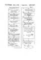
- FIG. 5is a schematic flow diagram illustrating the overall control program utilized in conjunction with the microprocessor.
- FIG. 6is a schematic flow diagram illustrating the program utilized for controlling movement of the piston of the present invention.
- FIG. 7is a schematic flow diagram illustrating the servo control program utilized in the flow diagram illustrated in FIG. 4.
- FIG. 1is a schematic block diagram of the control system 10 for the reciprocating piston respirator system of the present invention.
- the control systemutilizes a microprocessor 12 which generates a control signal 14 in response to a predictive servo control algorithm which utilizes data from input setting controls 16, detected position signal 18 from shaft encoder 20 and pressure signal 22 from pressure transducer 24.
- the signal produced by pulse-width modulator 26has an average power corresponding to control signal input 14.
- the pulse-width modulated signalis applied to motor 28 which rotates a shaft 30 with a torque proportional to the average power of the pulse-width modulated signal.
- the reciprocating piston respiratorcan utilize a threaded shaft mounted in a piston in the manner disclosed in the above cited U.S. Pat. No. 4,493,614 which produces a linear movement of the piston in response to the rotational movement of the shaft 30.
- Pulse-width modulator 26pulse-width modulates a supply voltage 32 provided from a voltage supply selector 34.
- Voltage supply selector 34selects either the utility input 36, internal battery input 38, or an external battery input 40 for use as supply voltage 32.
- the supply voltage 32is monitored by power sensor 42 to detect the magnitude of the supply voltage during application of peak torque during each stroke of the piston pump 26. This provides an accurate measurement of the magnitude of the supply voltage.
- the power sensor signal 44is applied to microprocessor 12 to adjust control signal 14 to provide the proper pulse-width modulation.
- Microprocessor 12may have one or more factor tables stored therein for generating position data to produce one or more preselected flow profiles. Torque and duty factor equations are also stored in the microprocssor 12 which utilizes frictional, pressure and inertial factors affecting movement of the piston in piston pump 46 for analysis using nonlinear time domain predictive servo control techniques.
- FIG. 2is a detailed block diagram of the microprocessor 12 and its associated devices.
- Microprocessor 12uses a central processing unit 50 comprising an Intel 8085AH-1.
- the CPUis a complete 8 bit parallel central processing unit with a 0.65 microsecond instruction cycle.
- the memory systemis coupled to CPU 50 through bus 52.
- the memoryincludes a read only memory 54, a read-write memory 56 and a non-volatile memory 58.
- Read only memory 54consists of a number of binary information cells which are programmed outside of the device to contain program and data information.
- Read-write memory 56consists of a number of binary information cells that, under program control, CPU 50 uses as a scratch pad for storing temporary data.
- Read-write memory 56may be implemented using static or dynamic random access memory components.
- An Intel 2128can be used which comprises a 16,384 bit static random access memory organized in 2,048 words by 8 bits. It employs fully static circuitry which eliminates the need for clocks, refresh, or address set and hold times. The auto power-down feature cuts power consumption when the device is disabled.
- Non-volatile random access memory (RAM) 58provides serial access static RAM access-ability and electronically erasable programmable read only memory (EEPROM) non-volatibility. Device operation is primarily controlled through instructions which are clocked into the device as 16-bit words.
- the non-volatile memoryprovides semi-permanent storage of maintenance parameter settings. Extra storage can be used to report failures within the system for maintenance analysis.
- Clock 60provides a clock pulse signal to bus 52 to control synchronous data transfers.
- Encoder 20provides a phase encoded signal which is differentiated by quadrature differentiator 62 which applies downcounts to downcounter 64 and upcounts to upcounter 66.
- Quadrature differentiator 62comprises a standard phase comparitor device.
- Downcounter 64 and upcounter 66can comprise Intel 8256 MURT timers which accumulate the up and down counts indicative of the position of the piston in the reciprocating piston respirator.
- the downcount signals 68 and upcount signal 70are applied to CPU 50.
- Clock 60generates a clock signal which is applied to CPU 50 segment timer 72 and countertimer 74.
- Clock 60provides timing to operate the system illustrated in FIG. 2.
- Segment timer 70can comprise an Intel 8254 timer for producing segment time signals indicating the transition point between time intervals.
- Segment timer 72is coupled to CPU 50 which computes the length of a segment interval. The length of the segment interval is loaded into segment timer 72. Segment timer 72 then provides a segment time signal indicating transition between time intervals.
- Countertimer 74can also comprise an Intel 8254 programmable interval timer compatible for PWM drive which produces the pulse-width modulated control signal 76 which is proportional to the average voltage to be applied to the drive motor 28.
- a 5.12 megahertz signalis clocked into the countertimer 74 from system clock 60.
- a 20 kilohertz signal divided from system clock 60acts as a gating signal for countertimer 74.
- Countertimer 74is operated in a retriggerable one shot mode to produce a 20 kilohertz pulse-width modulated (PWM) signal for driving piston motor 28.
- PWMpulse-width modulated
- countertimer 74is loaded by CPU 50 within an appropriate duty factor (DF) signal.
- the duty factor signalis computed by CPU 50 at each segment time regardless of the stroke length.
- the duty factor signalis derived from a torque equation based on information provided by encoder 20, parameters of the torque equation and detected parameter inputs through analog to digital converter (ADC) 78.
- Countertimer 74initiates a countdown sequence from a predetermined number loaded by CPU 50 with the onset of each 20 kilohertz pulse, counting at the 5.12 megahertz rate provided by system clock 60.
- the pulse-width modulated control signal 76 produced by countertimer 74is a 20 kilohertz pulse train with the width of each pulse directly proportional to the desired duty factor signal. This technique provides 255 different duty factor settings from full-off to full-on operation.
- the torque equation stored in CPU 50updates the torque required for the next segment of the total 50 segments throughout each stroke.
- the segment intervalis computed for each designated stroke at the end of each breath when the piston returns to its home position.
- all control settingsare updated and new piston equation parameters are calculated for the stroke.
- the new time interval for each strokeis loaded into segment timer 72.
- Segment timer 72is clocked by an 80 kilohertz signal divided by input from system clock 60. Segment timer 72 then counts the prescribed time interval and provides an interrupt signal to CPU 50.
- the interrupt to CPU 50invokes the torque equation at each segment time to update the duty factor signal applied to countertimer 74.
- ADC 78reads analog voltages from volume potentiometer 80, breath per minute potentiometer 82, flow rate potentiometer 84 power sensor 42 and pressure transducer 24.
- ADC 78digitizes the input signals with information representative of the voltage level of the signal.
- the ADCis an integrated circuit device with an 8 channel multiplexer, an 8 bit analog to digital convertor and microprocessor compatible controlled logic.
- the 8 channel multiplexercan be controlled by a microprocessor through a three bit address decoder with addresses loaded to select any one of eight single ended analog signals connected directly to the comparator.
- the ADCuses successive approximation conversion techniques featuring a high impedance chopper stabilized comparator, a 256 end compensated voltage divider and a successive approximation register.
- the comparison and converting methods used in the ADC 78eliminate the possibility for missing codes, non-monotonicity and the need for zero and full scale adjustment. Ratiometric conversion is provided by access to the reference voltage terminals.
- Volume potentiometer 80produces analog voltage indicative of the selected volume to be delivered.
- the breath per minute (BPM) potentiometer 82generates an analog signal indicative of the selected breath per minute rate to be delivered by the reciprocating piston respirator.
- Flow rate potentiometer 84produces an analog signal representative of the selected tidal flow rate (peak flow rate) to be delivered by the reciprocating piston respirator.
- the breath per minute input and flow rate inputdetermine the inspiratory to expiratory ratio.
- Power sensor 42senses the voltage level of the power source during application of peak torque during the inspiratory stroke of the piston.
- Pressure transducer 24provides a pressure signal at each segment time during the stroke.
- FIG. 1discloses the three voltages which are sensed, i.e., utility input power, internal battery power and external battery power.
- Pressure transducer 24provides a highly sensitive reading of pressure applied to the piston at each segment time which is used in the torque equation to compute the pressure which will be applied against the piston during movement in the next segment.
- the converter 78is coupled directly to bus 52 to transmit the digitzed data to CPU 50.
- Digital input ports 86provide high speed parallel data input from flow profile selector 88, limit switches 90 and optical zero detector 92.
- Flow profile selector 88provides a digital input of the flow profile desired to be produced by the reciprocating respirator.
- the digital inputcan comprise a digital selector switch.
- Limit switches 90are located within the reciprocating piston respirator cylinder to indicate movement of the piston beyond its limit points within the cylinder. The limit switches signal the CPU to stop movement of the piston immediately.
- Optical zero detector 92produces an optical detector adjacent the bulkhead to precisely locate the piston adjacent the bulkhead.
- Optical zero detector 92produces a zero reference input which provides a piston homing indicator at the end of each inhalation stroke. It assures an accurate piston reference position for the start of each breath.
- Digital output ports 94comprise parallel digital outputs which can be provided through peripheral interface adapters that are programmed for output. Digital output ports 94 can be used for high speed parallel data transmission or discreet output of any control compatible to binary format for switching external functions.
- CPU 50produces LED enunciator outputs 96 which comprise six front panel LEDs and one internal LED. The LED indicators are controlled by the microprocessor through discreet latch registers.
- Motor-in signal 98 and motor-out signal 100are also produced by digital output ports 94 to indicate the direction of the movement of the motor 28.
- Butter 99receives the PWM control signal 76, motor-in signal 98 and motor-out signal 100 and produces a polarized electrical power signal which is substantially proportional to the output force necessary to drive the piston pump 46.
- Display driver 102 and display 104provide an LCD display of data produced by the central processing unit 50.
- Display driver 102comprises a serial input LDC driver to drive LCD display 104.
- Datasuch as tidal volume, patient breath rate, inspiratory-expiratory ratio and other parameters of the system can be displayed on display 104.
- Serial port 106is coupled directly to bus 52.
- Bus 52comprises a full duplex asynchronous receiver/transmitter.
- a programmable baud rate generatoris included within serial port 106 to permit a variety of operating speeds without external components.
- Maintenance terminal 108comprises a dumb type terminal which can be plugged into a board socket. Under friendly software communicates with the maintenance terminal 108 to establish parameters of the system.
- FIG. 3comprises a graph of distance of movement of the piston within piston pump 46 vs. time.
- FIG. 3plots position values 200 versus segment times 202. Both the position values 200 and segment times 202 are arbitrary values as illustrated in FIG. 3. In accordance with the preferred embodiment, fifty separate segment times are utilized.
- Plot 204indicates the positional values 200 which the piston must assume at the plurality of substantially equally spaced segment times 202 to produce the selected flow profile 206 illustrated in FIG. 4.
- a plurality of factor tablescan be stored in microprocessor 12 to provide various positional values 200 to produce a plurality of selected flow profiles.
- Selected flow profile 206, illustrated in Figure, 4comprises a commonly used sinusoidally shaped flow profile.
- the factor tablesgenerate position data 208 which comprise curve 204.
- the plurality of substantially equally spaced segment times 202are separated by a plurality of substantially equal time intervals 210.
- the pistonmay assume a current actual position (L now ) 212 at a current segment time 214.
- the position value 200 of the current actual position 212differs from the position data 208 at current segment time 214.
- the torque equation of the present inventiondetermines the position value 200 of the position data 208 for next segment 216 which comprises the next position (L.sub. next) 218. By looking ahead in a predictive manner, the torque equation can determine the difference distance ( ⁇ D next ) 220 which the piston must move to achieve the next position 218 at the next segment time 222. The difference distance ( ⁇ D next ) 220 must be moved by the piston during the next segment interval 224.
- a pistonmay have been at a previous actual position (L last ) 226 at a previous segment time 228.
- the torque equationdetermines the previous difference distance ( ⁇ D last ) which the piston should have moved within the previous segment interval 232. Consequently, the torque equation determines the current actual position 212 of the piston at each current segment time 214 as it moves along curve 204 and compares the current actual position 212 with the next position 218 to prevent the torque required to move the piston the difference distance 220.
- FIG. 4illustrates the selected flow profile 206 produced at the respirator output 47. When the piston assumes the positions indicated by position data 208, produced by the factor table, the selected flow profile 206 is produced as illustrated in FIG. 4.
- FIG. 5comprises a flow diagram of the microprocessor illustrated in FIG. 2.
- the power-on reset function 152functions to reset the hardware.
- Start-up diagnostics 154proceed through the diagnostic system and indicate to the operator the operational condition of the system. For example, each of the LED's is flashed to indicate that they are working. Additionally, the LCD display is operated to show its working condition.
- the initialized hardware and software step 156functions to clear the registers so that the microprocessor can operate from a known state.
- the reset watch dog step 158is a safety step for triggering operation of the microprocessor if it has gone into a stop or runaway mode.
- the input digital step 160functions to read the flow profile selector 88, limit switches 90 and optical detector 92, as illustrated in FIG. 2.
- the scale analog step 162sets-up ADC 78 to periodically read front panel potentiometers 80, 82, 84, power supple 42, pressure transducer 24. Analog inputs are read about ten times per second.
- the check status of power and low pressure step 162checks the input power supply from the power sensor 42 and determines if the battery needs to be charged.
- the power control step 166selects the source of power to be used by the system.
- Alarm out step 168reveals the status of the entire system and determines if an alarm is necessary.
- Breath calculate step 170reads the parameter inputs of the systems and performs arithmetic operations.
- Load display buffer 172reads the operational values of the systems and feeds these values to the operator by way of display driver 102.
- LED control step 174reviews the data base status and controls the LEDs to be lit. The program then recirculates to the reset watchdog and software step 158.
- the piston operation programis schematically illustrated in the flow chart disclosed in FIG. 6.
- the programbegins with a start-up step 134 which initializes the program.
- the programthen proceeds to a seek step 136 which moves the piston in a forward direction toward a bulkhead.
- Decision block 138detects whenever the optical zero signal has been produced by optical zero detector 92. If the optical zero detector has not produced a signal, the program recirculates to the beginning of the seek step 136 to continue moving the piston. As soon as the optical zero mark is detected the program moves to the inner turn around step 140 which stops the drive motor 28 and produces a reverse torque in the motor to drive it away from the bulkhead.
- the programthen proceeds to the cleared zero sensor decision step 142 to detect if optical zero detector 92 has ceased producing a signal to indicate that the piston has cleared the optical zero detector as a result of the application of reverse torque in the inner turn around step 140. If optical zero detector 92 is producing a signal, the program recirculates to inner turn around step 140, as indicated by feedback loop 144. As soon as the piston clears the zero point, the program proceeds to the adjust friction term step 146 which functions to adjust the "A" term of the torque equation based on the actual piston travel time last stroke, which is representative of the static friction of the system.
- the "A" termcomprises the only free standing constant of the system and is adjusted at step 146 at the beginning of each stroke to compensate for differences in the predicted movement to the actual movement of the piston.
- the programthen proceeds to the expiration cycle and calls the servo control program disclosed in FIG. 7.
- the programthen proceeds to the encoder counter zero detected decision block 150 which detects if the shaft encoder of counter 166 has reached a full loaded value indicating that the piston has moved a predetermined programmed distance within the reciprocating piston respirator.
- the full volume to be deliveredwhich is selected on potentiometer 80, is loaded as a predetermined count in CPU 50.
- a comparisonis made between the count in up-counter 66 and the predetermined loaded value to determine if the piston has moved the preselected distance to provide the preselected volume.
- the programproceeds to outer turn around step 152 which stops the motor.
- the programthen proceeds to the patient trigger decision box step 154 to determine if a patient trigger has been received to proceed with the movement of the piston.
- the patient triggercan be produced by an inspiratory effort by the patient or an automatic trigger provided by the system. If no trigger has been received, the piston remains in a stopped or paused position.
- the programproceeds to the inspiration step 156 which calls the servo control.
- the piston control programproceeds to decision block 158 to determine if the optical zero has been detected. If it has not, it recirculates to the inspiration step 156 by way of return loop 160. If the optical zero has been detected, the program then proceeds to the inner turn around step 140 by way of return loop 162.
- FIG. 7comprises a flow diagram of the servo control program.
- the servo control programis called by the inspiration or expiration step of the piston operation program at the segment interrupt time.
- the segment interrupt timeis the segment time at which the end of a segment interval has been reached. Constants of the duty factor equation ae also read at this time.
- the torque equationis set forth below:
- ⁇ tperiod of a single time interval
- Kppressure proportionality factor
- L nextstored next position of said piston at a next segment time
- L lastprevious actual position of said piston at a previous segment time
- K ainertia factor of piston
- ⁇ D nextthe difference between position values for said next position (L next ) and said current actual position (L now );
- ⁇ D lastthe difference between position values for said current actual position (L now ) and said previous actual position (L last ).
- the torque equationis an equation which predicts the torque required to move the piston the desired distance indicated by the position data using the current actual position of the piston and the current pressure.
- the piston datais the data generated by a factor table stored in the microprocessor which determines the position which the piston must assume in the cylinder to produce a selected flow profile.
- the torque equationtherefore, determines the torque required to move the piston across the next segment using predictive servo control techniques.
- the torque equationuses time domain analysis and comprises a nonlinear equation. It is based upon distance measurements rather than velocity measurements and pressure measurements resulting in the nonlinear nature of the equation.
- the duty factor equationuses the result of the torque equation to produce the duty factor necessary to produce the torque to drive the piston across the next segment.
- Each of the constants which are read into the microprocessor pertaining to the torque and duty factor equationsare either derived empirically or calculated with the exception of the static friction term (A), which is adjusted during the course of each stroke.
- the duty factor equationis set forth below:
- K 1proportionality factor relating torque produced by said electric motor to current supplied to said electric motor
- K 2proportionality factor relating back-emf of said electric motor and velocity of said piston
- V smeasured supply voltage
- ⁇ tperiod of a single time interval.
- step 166the program proceeds to the read volume setting step 168 which reads the value of the potentiometer 80 indicating the select volume.
- step 170the program then proceeds to step 170 to calculate the total distance the piston is to move in accordance with the volume setting.
- step 172The program then proceeds to step 172 to apply the factor table for the selected flow profile input from flow profile selector 88.
- the total distance the piston is movedis factored by the selected factor table to produce the position data indicating the positional values which the piston must assume in a predetermined number of substantially equal segment times to produce the selected flow profile.
- step 174The program then proceeds to step 174 to store the locational position data generated from the selected factor table.
- the encoder counters comprising upcounters 66 and downcounters 64are then read by the program at the segment time to generate a current actual position (L now ) of the piston at step 176.
- the programthen proceeds to step 178 to compare the stored next position (L next ) for the next segment time with the current actual position (L now ) to compute a difference distance signal ( ⁇ D next ).
- step 180The program then computes a friction factor of the torque equation at step 180 to determine the frictional factors which affect the piston.
- step 182to read the pressure signal from pressure transducer 24. This information is used in step 184 to compute the pressure factor from the torque equation.
- the inertial factor of the torque equationis then computed at step 186.
- the programthen proceeds to step 188 to read the storage supply voltage magnitude detected at the midpoint of the last stroke, which is provided to the microprocessor by power sensor 42. This data is then used in step 190 together with the torque data and the resistance of the coils to compute the duty factor signal from the duty factor equation using computed torque and detected supply voltage magnitude.
- the programthen proceeds to step 192 to clamp the computed duty factor signal to the counter time acceptance range.
- the programthen proceeds to a return function at step 194.
- the present inventiontherefore provides a control system for smoothly moving a piston in a reciprocating piston respirator using predictive servo control techniques which results in a very precise manner of controlling the movement of the piston.
- the present inventiondoes not rely upon expensive and relatively inaccurate tachometers to produce velocity data, but rather, utilizes an inexpensive and accurate shaft encoder to produce locational position information.
- the present inventionuses nonlinear time domain analysis rather than linear frequency domain analysis to produce a much more accurate model of the required movement of the piston to produce the selected flow profiles. As a result, the flow profiles generated by the device are considerally more precise than profiles which could be produced by a much more expensive device using linear frequency domain analysis.
Landscapes
- Health & Medical Sciences (AREA)
- Engineering & Computer Science (AREA)
- General Health & Medical Sciences (AREA)
- Public Health (AREA)
- Anesthesiology (AREA)
- Biomedical Technology (AREA)
- Heart & Thoracic Surgery (AREA)
- Hematology (AREA)
- Life Sciences & Earth Sciences (AREA)
- Animal Behavior & Ethology (AREA)
- Emergency Medicine (AREA)
- Pulmonology (AREA)
- Veterinary Medicine (AREA)
- Human Computer Interaction (AREA)
- Manufacturing & Machinery (AREA)
- Physics & Mathematics (AREA)
- General Physics & Mathematics (AREA)
- Automation & Control Theory (AREA)
- Control Of Electric Motors In General (AREA)
- Compressor (AREA)
- Compressors, Vaccum Pumps And Other Relevant Systems (AREA)
- Flow Control (AREA)
Abstract
Description
______________________________________ Inventor U.S. Pat. No. Issue Date ______________________________________ McGuire 3,610,782 October 5, 1971 Perkins et al 4,276,003 June 30, 1981 Thomas et al 4,384,825 May 24, 1983 Schneider et al 4,498,843 February 12, 1985 ______________________________________
T=A+B(Δnext/t)+C(ΔD next/t).sup.2 +Kp+Kp(P.sub.now +ΔD.sub.next)+Ka(ΔD.sub.next -ΔD.sub.last)/Δt.sup.2
DF=(T·r+K.sub.1 K.sub.2 ΔD.sub.next /Δt)/k.sub.1 V.sub.5
Claims (11)
Priority Applications (6)
| Application Number | Priority Date | Filing Date | Title |
|---|---|---|---|
| US06/753,275US4617637A (en) | 1985-07-09 | 1985-07-09 | Servo control system for a reciprocating piston respirator |
| CA000510352ACA1237507A (en) | 1985-07-09 | 1986-05-29 | Servo control system for a reciprocating piston respirator |
| AU59984/86AAU586376B2 (en) | 1985-07-09 | 1986-06-05 | Servo control system for a reciprocating piston respirator |
| EP19860903995EP0229781A4 (en) | 1985-07-09 | 1986-06-05 | Servo control system for a reciprocating piston respirator. |
| PCT/US1986/001258WO1987000319A1 (en) | 1985-07-09 | 1986-06-05 | Servo control system for a reciprocating piston respirator |
| DK115387ADK115387A (en) | 1985-07-09 | 1987-03-06 | SERVICE CONTROL ARRANGEMENT FOR A RESPIRATOR WITH RECIPROCATING STAMP |
Applications Claiming Priority (1)
| Application Number | Priority Date | Filing Date | Title |
|---|---|---|---|
| US06/753,275US4617637A (en) | 1985-07-09 | 1985-07-09 | Servo control system for a reciprocating piston respirator |
Publications (1)
| Publication Number | Publication Date |
|---|---|
| US4617637Atrue US4617637A (en) | 1986-10-14 |
Family
ID=25029953
Family Applications (1)
| Application Number | Title | Priority Date | Filing Date |
|---|---|---|---|
| US06/753,275Expired - LifetimeUS4617637A (en) | 1985-07-09 | 1985-07-09 | Servo control system for a reciprocating piston respirator |
Country Status (6)
| Country | Link |
|---|---|
| US (1) | US4617637A (en) |
| EP (1) | EP0229781A4 (en) |
| AU (1) | AU586376B2 (en) |
| CA (1) | CA1237507A (en) |
| DK (1) | DK115387A (en) |
| WO (1) | WO1987000319A1 (en) |
Cited By (92)
| Publication number | Priority date | Publication date | Assignee | Title |
|---|---|---|---|---|
| EP0202043A3 (en)* | 1985-05-11 | 1987-12-23 | Lucas Industries Public Limited Company | Control for a stepper motor or other synchronous motor |
| JPS6485667A (en)* | 1986-11-04 | 1989-03-30 | Bird Products Corp | Method and ventilator for giving plural respirations which are substantially same |
| EP0283141A3 (en)* | 1987-02-21 | 1989-10-11 | University Of Manitoba | Lung ventilator device |
| US4912753A (en)* | 1988-04-04 | 1990-03-27 | Hughes Aircraft Company | Robot axis controller employing feedback and open loop (feedforward) control |
| US4919596A (en)* | 1987-12-04 | 1990-04-24 | Pacesetter Infusion, Ltd. | Fluid delivery control and monitoring apparatus for a medication infusion system |
| US4957107A (en)* | 1988-05-10 | 1990-09-18 | Sipin Anatole J | Gas delivery means |
| US4971049A (en)* | 1989-11-06 | 1990-11-20 | Pulsair, Inc. | Pressure sensor control device for supplying oxygen |
| EP0322503A3 (en)* | 1987-12-29 | 1991-09-25 | Daihatsu Diesel Mfg. Co., Ltd. | Fluid apparatus |
| US5092739A (en)* | 1987-05-14 | 1992-03-03 | Nomix Manufacturing Company Limited | Electronic pump control |
| US5092326A (en)* | 1987-11-19 | 1992-03-03 | Winn Bryan D | Apparatus and method for a ventilator system |
| US5097424A (en)* | 1986-12-31 | 1992-03-17 | Elmed Genevri Srl | Constant flow and controlled ventilation, pressure responsive pulmotor |
| WO1992014930A1 (en)* | 1991-02-19 | 1992-09-03 | Milton Roy Company | Stator current based malfunction detecting system in a variable flow delivery pump |
| WO1992014505A3 (en)* | 1991-02-19 | 1992-12-10 | Univ Manitoba | Piston-based ventilator design and operation |
| USH1282H (en) | 1990-02-05 | 1994-02-01 | The United States Of America As Represented By The Secretary Of The Army | Fluidic volume-cycled respirator |
| FR2695320A1 (en)* | 1992-09-04 | 1994-03-11 | Sefam | Regulation method for air flow in respirator - using rate of change of flow samples to detect inspiration, and comparison of flow with integral of inspiration flow to detect expiration |
| US5341497A (en)* | 1991-10-16 | 1994-08-23 | Ohmeda Inc. | Method and apparatus for a computer system to detect program faults and permit recovery from such faults |
| WO1994027201A1 (en)* | 1993-05-11 | 1994-11-24 | Mannesmann Rexroth Gmbh | Control for a hydraulic drive |
| US5425716A (en)* | 1991-08-09 | 1995-06-20 | Atom Kabushiki Kaisha | Infusion apparatus |
| US5474062A (en)* | 1987-11-04 | 1995-12-12 | Bird Products Corporation | Medical ventilator |
| WO1996011717A1 (en)* | 1994-10-14 | 1996-04-25 | Bird Products Corporation | Portable drag compressor powered mechanical ventilator |
| FR2733688A1 (en)* | 1995-05-05 | 1996-11-08 | Saime Sarl | Respiratory assisting apparatus using diaphragm compressor |
| WO1997021154A1 (en)* | 1995-12-01 | 1997-06-12 | Simeon Krumov Lekarski | Automatic system and method for regulation of the operation of an automatic valve |
| US5673689A (en)* | 1995-02-09 | 1997-10-07 | Puritan Bennett Corporation | Piston based ventilator |
| US5676525A (en)* | 1993-02-19 | 1997-10-14 | Neovation Ag | Vacuum limiting medical pump |
| US5829335A (en)* | 1993-05-11 | 1998-11-03 | Mannesmann Rexroth Gmbh | Control for hydraulic drive or actuator |
| US6076523A (en)* | 1998-01-15 | 2000-06-20 | Nellcor Puritan Bennett | Oxygen blending in a piston ventilator |
| US6135967A (en) | 1999-04-26 | 2000-10-24 | Fiorenza; Anthony Joseph | Respiratory ventilator with automatic flow calibration |
| US6142150A (en)* | 1998-03-24 | 2000-11-07 | Nellcor Puritan-Bennett | Compliance compensation in volume control ventilator |
| US6192283B1 (en) | 1998-07-31 | 2001-02-20 | Siemens Energy & Automation, Inc. | Method and apparatus for adaptive control of a system or device |
| US6240919B1 (en) | 1999-06-07 | 2001-06-05 | Macdonald John J. | Method for providing respiratory airway support pressure |
| US6321748B1 (en)* | 1998-03-10 | 2001-11-27 | Nellcor Puritan Bennett | Closed loop control in a piston ventilator |
| US6478026B1 (en) | 1999-03-13 | 2002-11-12 | Thomas J. Wood | Nasal ventilation interface |
| US6537032B1 (en)* | 1999-09-24 | 2003-03-25 | Daikin Industries, Ltd. | Load dependent variable speed hydraulic unit |
| US6679259B2 (en)* | 2000-08-22 | 2004-01-20 | DRäGER MEDIZINTECHNIK GMBH | Process for controlling a respirator |
| US20040134498A1 (en)* | 2001-10-25 | 2004-07-15 | Roger Strickland | Nasal cannula |
| US20040182397A1 (en)* | 2003-03-21 | 2004-09-23 | Innomed Technologies, Inc. | Nasal interface including ventilation insert |
| US20050028821A1 (en)* | 2003-08-06 | 2005-02-10 | Wood Thomas J. | Nasal interface and system including ventilation insert |
| US20050028823A1 (en)* | 2000-03-13 | 2005-02-10 | Wood Thomas J. | Nasal ventilation interface |
| US20050039757A1 (en)* | 1999-03-13 | 2005-02-24 | Wood Thomas J. | Ventilation interface for sleep apnea therapy |
| US20050045182A1 (en)* | 2003-08-06 | 2005-03-03 | Wood Thomas J. | Nasal interface and system including ventilation insert |
| US20050126574A1 (en)* | 2000-03-13 | 2005-06-16 | Wood Thomas J. | Ventilation interface for sleep apnea therapy |
| US20050133040A1 (en)* | 2003-09-10 | 2005-06-23 | Wood Thomas J. | Nasal interface and system including ventilation insert |
| US20050193843A1 (en)* | 2004-02-29 | 2005-09-08 | Niels Laugwitz | Control device and method for a vibratory machine |
| US20050236000A1 (en)* | 2003-08-05 | 2005-10-27 | Wood Thomas J | Nasal ventilation interface and system |
| US20060029634A1 (en)* | 2004-08-06 | 2006-02-09 | Berg Michael C | Porous structures |
| US20060124131A1 (en)* | 2004-12-10 | 2006-06-15 | Respcare, Inc. | Hybrid ventilation mask with nasal interface and method for configuring such a mask |
| US7191781B2 (en) | 2003-08-05 | 2007-03-20 | Innomed Technologies, Inc. | Nasal ventilation interface and system |
| USD550836S1 (en) | 2005-07-06 | 2007-09-11 | Respcare, Inc. | Ventilation interface |
| USD551340S1 (en) | 2000-03-13 | 2007-09-18 | Innomed Technologies, Inc. | Nasal interface |
| US20070215154A1 (en)* | 2006-03-15 | 2007-09-20 | Borrello Michael A | Closed loop control system for a high frequency oscillation ventilator |
| US20070221221A1 (en)* | 2006-02-23 | 2007-09-27 | Cooke Richard H | Ventilator for Rapid Response to Respiratory Disease Conditions |
| US20070272249A1 (en)* | 2006-05-10 | 2007-11-29 | Sanjay Chandran | Ventilation interface |
| US20080129063A1 (en)* | 2006-12-01 | 2008-06-05 | Samsung Electronics Co., Ltd. | Vacuum type pickup apparatus and vacuum type pickup Method |
| USD583047S1 (en) | 2007-04-09 | 2008-12-16 | Respcare, Inc. | Ventilation interface |
| USD591419S1 (en) | 2008-01-08 | 2009-04-28 | Mergenet Solutions, Inc. | Ventilation portion of a ventilation apparatus |
| US7559327B2 (en) | 2005-05-31 | 2009-07-14 | Respcare, Inc. | Ventilation interface |
| USD597199S1 (en) | 2006-04-28 | 2009-07-28 | Resmed Limited | Respiratory mask frame |
| US7658189B2 (en) | 2003-12-31 | 2010-02-09 | Resmed Limited | Compact oronasal patient interface |
| USD623288S1 (en) | 2006-04-28 | 2010-09-07 | Resmed Limited | Patient interface |
| US20100306992A1 (en)* | 2006-02-23 | 2010-12-09 | Richard Henry Cooke | Ventilator for Rapid Response to Respiratory Disease Conditions |
| US7958893B2 (en) | 2001-09-07 | 2011-06-14 | Resmed Limited | Cushion for a respiratory mask assembly |
| US8136525B2 (en) | 2004-12-24 | 2012-03-20 | Resmed Limited | Mask system |
| US8261745B2 (en) | 2004-12-10 | 2012-09-11 | Respcare, Inc. | Ventilation interface |
| US8291906B2 (en) | 2008-06-04 | 2012-10-23 | Resmed Limited | Patient interface systems |
| US8297285B2 (en) | 2006-07-28 | 2012-10-30 | Resmed Limited | Delivery of respiratory therapy |
| US8421368B2 (en) | 2007-07-31 | 2013-04-16 | Lsi Industries, Inc. | Control of light intensity using pulses of a fixed duration and frequency |
| US8485192B2 (en) | 2005-01-12 | 2013-07-16 | Resmed Limited | Cushion for patient interface |
| US8517023B2 (en) | 2007-01-30 | 2013-08-27 | Resmed Limited | Mask system with interchangeable headgear connectors |
| US8522784B2 (en) | 2008-03-04 | 2013-09-03 | Resmed Limited | Mask system |
| US8604709B2 (en) | 2007-07-31 | 2013-12-10 | Lsi Industries, Inc. | Methods and systems for controlling electrical power to DC loads |
| US8789532B2 (en) | 2006-03-10 | 2014-07-29 | Respcare, Inc. | Ventilation mask |
| US8807135B2 (en) | 2004-06-03 | 2014-08-19 | Resmed Limited | Cushion for a patient interface |
| US8869797B2 (en) | 2007-04-19 | 2014-10-28 | Resmed Limited | Cushion and cushion to frame assembly mechanism for patient interface |
| US8869798B2 (en) | 2008-09-12 | 2014-10-28 | Resmed Limited | Foam-based interfacing structure method and apparatus |
| US8903577B2 (en) | 2009-10-30 | 2014-12-02 | Lsi Industries, Inc. | Traction system for electrically powered vehicles |
| US8905031B2 (en) | 2008-06-04 | 2014-12-09 | Resmed Limited | Patient interface systems |
| US8944061B2 (en) | 2005-10-14 | 2015-02-03 | Resmed Limited | Cushion to frame assembly mechanism |
| US20150153747A1 (en)* | 2012-08-06 | 2015-06-04 | Mitsubishi Electric Corporation | Torque control device |
| US9138553B2 (en) | 2000-03-13 | 2015-09-22 | Innomed Technologies, Inc. | Ventilation interface for sleep apnea therapy |
| US9162034B2 (en) | 2006-07-28 | 2015-10-20 | Resmed Limited | Delivery of respiratory therapy |
| US9381316B2 (en) | 2005-10-25 | 2016-07-05 | Resmed Limited | Interchangeable mask assembly |
| US9480809B2 (en) | 2007-07-30 | 2016-11-01 | Resmed Limited | Patient interface |
| CN106267509A (en)* | 2016-08-03 | 2017-01-04 | 刘芳 | A kind of air flue humidification pump |
| US9987450B2 (en) | 2008-03-04 | 2018-06-05 | Resmed Limited | Interface including a foam cushioning element |
| US10166357B2 (en) | 2006-12-15 | 2019-01-01 | Resmed Limited | Delivery of respiratory therapy with nasal interface |
| US10307554B2 (en) | 2002-11-06 | 2019-06-04 | Resmed Limited | Mask and components thereof |
| CN110987506A (en)* | 2019-12-26 | 2020-04-10 | 成都康拓兴业科技有限责任公司 | Breathing simulation system and control method |
| US10786642B2 (en) | 2009-01-30 | 2020-09-29 | ResMed Pty Ltd | Patient interface structure and method/tool for manufacturing same |
| US11129953B2 (en) | 2008-03-04 | 2021-09-28 | ResMed Pty Ltd | Foam respiratory mask |
| US11331447B2 (en) | 2008-03-04 | 2022-05-17 | ResMed Pty Ltd | Mask system with snap-fit shroud |
| US20240291409A1 (en)* | 2022-06-08 | 2024-08-29 | Zhejiang University Advanced Electrical Equipment Innovation Center | Nonlinear predictive position control method suitable for biaxial permanent magnet servo system |
| CN118793600A (en)* | 2024-09-12 | 2024-10-18 | 成都水木医疗科技有限公司 | Sinusoidal flow generator and generation method for testing ventilator and anesthesia system |
Citations (15)
| Publication number | Priority date | Publication date | Assignee | Title |
|---|---|---|---|---|
| US1406141A (en)* | 1921-03-05 | 1922-02-07 | Anston George | Respiratory apparatus |
| US4108574A (en)* | 1977-01-21 | 1978-08-22 | International Paper Company | Apparatus and method for the indirect measurement and control of the flow rate of a liquid in a piping system |
| GB1541852A (en)* | 1975-10-24 | 1979-03-07 | Hoffmann La Roche | Respiration apparatus |
| US4197576A (en)* | 1976-08-04 | 1980-04-08 | Juan Martin Sanchez | Adaptive-predictive control system |
| US4215681A (en)* | 1975-08-07 | 1980-08-05 | Assistance Technique Medicale Serdahl, S.A. | Respirator for the treatment of persons suffering from respiratory insufficiencies |
| US4276003A (en)* | 1977-03-04 | 1981-06-30 | California Institute Of Technology | Reciprocating piston pump system with screw drive |
| US4277832A (en)* | 1979-10-01 | 1981-07-07 | General Electric Company | Fluid flow control system |
| US4326837A (en)* | 1978-12-15 | 1982-04-27 | Gilson Medical Electronics | Pumping apparatus using a stepping motor |
| US4358322A (en)* | 1976-05-27 | 1982-11-09 | Uop Inc. | Process for separating a ketose from an aldose by selective adsorption |
| US4384825A (en)* | 1980-10-31 | 1983-05-24 | The Bendix Corporation | Personal sampling pump |
| US4425805A (en)* | 1980-10-31 | 1984-01-17 | Tokyo Shibaura Denki Kabushiki Kaisha | Respiration flowmeter |
| US4432063A (en)* | 1981-10-06 | 1984-02-14 | Cincinnati Milacron Inc. | Apparatus for automatically moving a robot arm along a nonprogrammed path |
| US4458321A (en)* | 1981-08-19 | 1984-07-03 | The Charles Stark Draper Laboratory, Inc. | Self-teaching robot feedback system |
| US4493614A (en)* | 1982-10-08 | 1985-01-15 | Lifecare Services, Inc. | Pump for a portable ventilator |
| US4498843A (en)* | 1982-08-02 | 1985-02-12 | Schneider Philip H | Insulin infusion pump |
Family Cites Families (2)
| Publication number | Priority date | Publication date | Assignee | Title |
|---|---|---|---|---|
| US3610782A (en)* | 1969-10-06 | 1971-10-05 | Precision Control Products Cor | Controlled pump |
| US4036221A (en)* | 1972-05-01 | 1977-07-19 | Sutter Hospitals Medical Research Foundation | Respirator |
- 1985
- 1985-07-09USUS06/753,275patent/US4617637A/ennot_activeExpired - Lifetime
- 1986
- 1986-05-29CACA000510352Apatent/CA1237507A/ennot_activeExpired
- 1986-06-05WOPCT/US1986/001258patent/WO1987000319A1/ennot_activeApplication Discontinuation
- 1986-06-05AUAU59984/86Apatent/AU586376B2/ennot_activeCeased
- 1986-06-05EPEP19860903995patent/EP0229781A4/ennot_activeWithdrawn
- 1987
- 1987-03-06DKDK115387Apatent/DK115387A/ennot_activeApplication Discontinuation
Patent Citations (15)
| Publication number | Priority date | Publication date | Assignee | Title |
|---|---|---|---|---|
| US1406141A (en)* | 1921-03-05 | 1922-02-07 | Anston George | Respiratory apparatus |
| US4215681A (en)* | 1975-08-07 | 1980-08-05 | Assistance Technique Medicale Serdahl, S.A. | Respirator for the treatment of persons suffering from respiratory insufficiencies |
| GB1541852A (en)* | 1975-10-24 | 1979-03-07 | Hoffmann La Roche | Respiration apparatus |
| US4358322A (en)* | 1976-05-27 | 1982-11-09 | Uop Inc. | Process for separating a ketose from an aldose by selective adsorption |
| US4197576A (en)* | 1976-08-04 | 1980-04-08 | Juan Martin Sanchez | Adaptive-predictive control system |
| US4108574A (en)* | 1977-01-21 | 1978-08-22 | International Paper Company | Apparatus and method for the indirect measurement and control of the flow rate of a liquid in a piping system |
| US4276003A (en)* | 1977-03-04 | 1981-06-30 | California Institute Of Technology | Reciprocating piston pump system with screw drive |
| US4326837A (en)* | 1978-12-15 | 1982-04-27 | Gilson Medical Electronics | Pumping apparatus using a stepping motor |
| US4277832A (en)* | 1979-10-01 | 1981-07-07 | General Electric Company | Fluid flow control system |
| US4384825A (en)* | 1980-10-31 | 1983-05-24 | The Bendix Corporation | Personal sampling pump |
| US4425805A (en)* | 1980-10-31 | 1984-01-17 | Tokyo Shibaura Denki Kabushiki Kaisha | Respiration flowmeter |
| US4458321A (en)* | 1981-08-19 | 1984-07-03 | The Charles Stark Draper Laboratory, Inc. | Self-teaching robot feedback system |
| US4432063A (en)* | 1981-10-06 | 1984-02-14 | Cincinnati Milacron Inc. | Apparatus for automatically moving a robot arm along a nonprogrammed path |
| US4498843A (en)* | 1982-08-02 | 1985-02-12 | Schneider Philip H | Insulin infusion pump |
| US4493614A (en)* | 1982-10-08 | 1985-01-15 | Lifecare Services, Inc. | Pump for a portable ventilator |
Non-Patent Citations (6)
| Title |
|---|
| Coles et al., "Computer Control of Respiration and Anaesthesia", Medical and Biological Engineering, May 1973, pp. 262-267. |
| Coles et al., Computer Control of Respiration and Anaesthesia , Medical and Biological Engineering, May 1973, pp. 262 267.* |
| Jain et al., "A Control System for Long-Term Ventilation of the Lungs", IEEE Transactions on Biomedical Engineering, Jan. 1972, pp. 47-53. |
| Jain et al., A Control System for Long Term Ventilation of the Lungs , IEEE Transactions on Biomedical Engineering, Jan. 1972, pp. 47 53.* |
| Moore et al., "Improved Algorithm for Direct Digital Control", Instruments and Control Systems, Jan. 1970, pp. 70-74. |
| Moore et al., Improved Algorithm for Direct Digital Control , Instruments and Control Systems, Jan. 1970, pp. 70 74.* |
Cited By (245)
| Publication number | Priority date | Publication date | Assignee | Title |
|---|---|---|---|---|
| EP0202043A3 (en)* | 1985-05-11 | 1987-12-23 | Lucas Industries Public Limited Company | Control for a stepper motor or other synchronous motor |
| JPS6485667A (en)* | 1986-11-04 | 1989-03-30 | Bird Products Corp | Method and ventilator for giving plural respirations which are substantially same |
| EP0282675A3 (en)* | 1986-11-04 | 1990-01-03 | Bird Products Corporation | Flow control valve for a medical ventilator |
| US5097424A (en)* | 1986-12-31 | 1992-03-17 | Elmed Genevri Srl | Constant flow and controlled ventilation, pressure responsive pulmotor |
| EP0283141A3 (en)* | 1987-02-21 | 1989-10-11 | University Of Manitoba | Lung ventilator device |
| US5107830A (en)* | 1987-02-21 | 1992-04-28 | University Of Manitoba | Lung ventilator device |
| US5044362A (en)* | 1987-02-21 | 1991-09-03 | University Of Manitoba | Lung ventilator device |
| US5092739A (en)* | 1987-05-14 | 1992-03-03 | Nomix Manufacturing Company Limited | Electronic pump control |
| US5474062A (en)* | 1987-11-04 | 1995-12-12 | Bird Products Corporation | Medical ventilator |
| US5092326A (en)* | 1987-11-19 | 1992-03-03 | Winn Bryan D | Apparatus and method for a ventilator system |
| US4919596A (en)* | 1987-12-04 | 1990-04-24 | Pacesetter Infusion, Ltd. | Fluid delivery control and monitoring apparatus for a medication infusion system |
| EP0322503A3 (en)* | 1987-12-29 | 1991-09-25 | Daihatsu Diesel Mfg. Co., Ltd. | Fluid apparatus |
| US4912753A (en)* | 1988-04-04 | 1990-03-27 | Hughes Aircraft Company | Robot axis controller employing feedback and open loop (feedforward) control |
| US4957107A (en)* | 1988-05-10 | 1990-09-18 | Sipin Anatole J | Gas delivery means |
| WO1991006336A1 (en)* | 1989-11-06 | 1991-05-16 | Rotariu William J | Pressure sensor control device for supplying oxygen |
| US4971049A (en)* | 1989-11-06 | 1990-11-20 | Pulsair, Inc. | Pressure sensor control device for supplying oxygen |
| USH1282H (en) | 1990-02-05 | 1994-02-01 | The United States Of America As Represented By The Secretary Of The Army | Fluidic volume-cycled respirator |
| WO1992014505A3 (en)* | 1991-02-19 | 1992-12-10 | Univ Manitoba | Piston-based ventilator design and operation |
| JPH06502222A (en)* | 1991-02-19 | 1994-03-10 | マイクロエレクトロニクス アンド コンピューター テクノロジー コーポレイション | Improved Direct Copper Lighting Method and Solution |
| US5540222A (en)* | 1991-02-19 | 1996-07-30 | University Of Manitoba | Piston-based ventilator design and operation |
| US5201636A (en)* | 1991-02-19 | 1993-04-13 | Milton Roy Company | Stator current based malfunction detecting system in a variable flow delivery pump |
| JP2512669B2 (en) | 1991-02-19 | 1996-07-03 | ユニヴァーシティ オブ マニトバ | Piston type ventilation device |
| WO1992014930A1 (en)* | 1991-02-19 | 1992-09-03 | Milton Roy Company | Stator current based malfunction detecting system in a variable flow delivery pump |
| EP0691135A1 (en)* | 1991-02-19 | 1996-01-10 | University Of Manitoba | Piston-based ventilator design and operation |
| US5425716A (en)* | 1991-08-09 | 1995-06-20 | Atom Kabushiki Kaisha | Infusion apparatus |
| US5341497A (en)* | 1991-10-16 | 1994-08-23 | Ohmeda Inc. | Method and apparatus for a computer system to detect program faults and permit recovery from such faults |
| FR2695320A1 (en)* | 1992-09-04 | 1994-03-11 | Sefam | Regulation method for air flow in respirator - using rate of change of flow samples to detect inspiration, and comparison of flow with integral of inspiration flow to detect expiration |
| US5676525A (en)* | 1993-02-19 | 1997-10-14 | Neovation Ag | Vacuum limiting medical pump |
| DE4415055C1 (en)* | 1993-05-11 | 1995-05-18 | Rexroth Mannesmann Gmbh | Hydraulic drive control |
| EP0626628A1 (en)* | 1993-05-11 | 1994-11-30 | MANNESMANN REXROTH GmbH | Control system for a hydraulic drive |
| WO1994027201A1 (en)* | 1993-05-11 | 1994-11-24 | Mannesmann Rexroth Gmbh | Control for a hydraulic drive |
| US5829335A (en)* | 1993-05-11 | 1998-11-03 | Mannesmann Rexroth Gmbh | Control for hydraulic drive or actuator |
| US5881722A (en) | 1994-10-14 | 1999-03-16 | Bird Products Corporation | Portable drag compressor powered mechanical ventilator |
| US6526970B2 (en) | 1994-10-14 | 2003-03-04 | Devries Douglas F. | Portable drag compressor powered mechanical ventilator |
| US7849854B2 (en) | 1994-10-14 | 2010-12-14 | Bird Products Corporation | Portable drag compressor powered mechanical ventilator |
| US5694926A (en) | 1994-10-14 | 1997-12-09 | Bird Products Corporation | Portable drag compressor powered mechanical ventilator |
| WO1996011717A1 (en)* | 1994-10-14 | 1996-04-25 | Bird Products Corporation | Portable drag compressor powered mechanical ventilator |
| US5868133A (en)* | 1994-10-14 | 1999-02-09 | Bird Products Corporation | Portable drag compressor powered mechanical ventilator |
| US20070144521A1 (en)* | 1994-10-14 | 2007-06-28 | Bird Products Corporation | Portable drag compressor powered mechanical ventilator |
| US6877511B2 (en) | 1994-10-14 | 2005-04-12 | Bird Products Corporation | Portable drag compressor powered mechanical ventilator |
| US20090084381A1 (en)* | 1994-10-14 | 2009-04-02 | Bird Products Corporation | Portable drag compressor powered mechanical ventilator |
| US7222623B2 (en) | 1994-10-14 | 2007-05-29 | Birds Products Corporation | Portable drag compressor powered mechanical ventilator |
| US5915382A (en)* | 1995-02-09 | 1999-06-29 | Puritan-Bennett Corporation | Piston based ventillator |
| US5673689A (en)* | 1995-02-09 | 1997-10-07 | Puritan Bennett Corporation | Piston based ventilator |
| FR2733688A1 (en)* | 1995-05-05 | 1996-11-08 | Saime Sarl | Respiratory assisting apparatus using diaphragm compressor |
| WO1997021154A1 (en)* | 1995-12-01 | 1997-06-12 | Simeon Krumov Lekarski | Automatic system and method for regulation of the operation of an automatic valve |
| US6412483B1 (en)* | 1998-01-15 | 2002-07-02 | Nellcor Puritan Bennett | Oxygen blending in a piston ventilator |
| US6076523A (en)* | 1998-01-15 | 2000-06-20 | Nellcor Puritan Bennett | Oxygen blending in a piston ventilator |
| US6321748B1 (en)* | 1998-03-10 | 2001-11-27 | Nellcor Puritan Bennett | Closed loop control in a piston ventilator |
| US6142150A (en)* | 1998-03-24 | 2000-11-07 | Nellcor Puritan-Bennett | Compliance compensation in volume control ventilator |
| US6192283B1 (en) | 1998-07-31 | 2001-02-20 | Siemens Energy & Automation, Inc. | Method and apparatus for adaptive control of a system or device |
| US6478026B1 (en) | 1999-03-13 | 2002-11-12 | Thomas J. Wood | Nasal ventilation interface |
| US6997177B2 (en) | 1999-03-13 | 2006-02-14 | Inno Med Technologies, Inc. | Ventilation interface for sleep apnea therapy |
| US20050039757A1 (en)* | 1999-03-13 | 2005-02-24 | Wood Thomas J. | Ventilation interface for sleep apnea therapy |
| US6135967A (en) | 1999-04-26 | 2000-10-24 | Fiorenza; Anthony Joseph | Respiratory ventilator with automatic flow calibration |
| US6240919B1 (en) | 1999-06-07 | 2001-06-05 | Macdonald John J. | Method for providing respiratory airway support pressure |
| US6537032B1 (en)* | 1999-09-24 | 2003-03-25 | Daikin Industries, Ltd. | Load dependent variable speed hydraulic unit |
| US9919121B2 (en) | 2000-03-13 | 2018-03-20 | Innomed Healthscience, Inc. | Ventilation interface for sleep apnea therapy |
| US7188624B2 (en) | 2000-03-13 | 2007-03-13 | Innomed Technologies Inc. | Ventilation interface for sleep apnea therapy |
| USD551340S1 (en) | 2000-03-13 | 2007-09-18 | Innomed Technologies, Inc. | Nasal interface |
| US9138553B2 (en) | 2000-03-13 | 2015-09-22 | Innomed Technologies, Inc. | Ventilation interface for sleep apnea therapy |
| US20050126574A1 (en)* | 2000-03-13 | 2005-06-16 | Wood Thomas J. | Ventilation interface for sleep apnea therapy |
| US6994089B2 (en) | 2000-03-13 | 2006-02-07 | Innomed Technologies, Inc | Nasal ventilation interface |
| US20050028823A1 (en)* | 2000-03-13 | 2005-02-10 | Wood Thomas J. | Nasal ventilation interface |
| US7059328B2 (en) | 2000-03-13 | 2006-06-13 | Innomed Technologies, Inc. | Ventilation interface for sleep apnea therapy |
| US6679259B2 (en)* | 2000-08-22 | 2004-01-20 | DRäGER MEDIZINTECHNIK GMBH | Process for controlling a respirator |
| US8733358B2 (en) | 2001-09-07 | 2014-05-27 | Resmed Limited | Cushion for a respiratory mask assembly |
| US10850057B2 (en) | 2001-09-07 | 2020-12-01 | ResMed Pty Ltd | Cushion for a respiratory mask assembly |
| US9724488B2 (en) | 2001-09-07 | 2017-08-08 | Resmed Limited | Cushion for a respiratory mask assembly |
| US7958893B2 (en) | 2001-09-07 | 2011-06-14 | Resmed Limited | Cushion for a respiratory mask assembly |
| US7047974B2 (en) | 2001-10-25 | 2006-05-23 | Innomed Technologies, Inc. | Nasal cannula |
| US20040134498A1 (en)* | 2001-10-25 | 2004-07-15 | Roger Strickland | Nasal cannula |
| US10307554B2 (en) | 2002-11-06 | 2019-06-04 | Resmed Limited | Mask and components thereof |
| US10940283B2 (en) | 2002-11-06 | 2021-03-09 | ResMed Pty Ltd | Mask and components thereof |
| US11406784B2 (en) | 2002-11-06 | 2022-08-09 | ResMed Pty Ltd | Mask and components thereof |
| US11666725B2 (en) | 2002-11-06 | 2023-06-06 | ResMed Pty Ltd | Mask and components thereof |
| US20040182397A1 (en)* | 2003-03-21 | 2004-09-23 | Innomed Technologies, Inc. | Nasal interface including ventilation insert |
| US7234465B2 (en) | 2003-08-05 | 2007-06-26 | Innomed Technologies, Inc. | Nasal ventilation interface and system |
| US7191781B2 (en) | 2003-08-05 | 2007-03-20 | Innomed Technologies, Inc. | Nasal ventilation interface and system |
| US20060150982A1 (en)* | 2003-08-05 | 2006-07-13 | Wood Thomas J | Nasal ventilation interface and system |
| US20050236000A1 (en)* | 2003-08-05 | 2005-10-27 | Wood Thomas J | Nasal ventilation interface and system |
| US7000613B2 (en) | 2003-08-06 | 2006-02-21 | Innomed Technologies, Inc. | Nasal interface and system including ventilation insert |
| US20050028821A1 (en)* | 2003-08-06 | 2005-02-10 | Wood Thomas J. | Nasal interface and system including ventilation insert |
| US20050045182A1 (en)* | 2003-08-06 | 2005-03-03 | Wood Thomas J. | Nasal interface and system including ventilation insert |
| US7472707B2 (en) | 2003-08-06 | 2009-01-06 | Innomed Technologies, Inc. | Nasal interface and system including ventilation insert |
| US20050133040A1 (en)* | 2003-09-10 | 2005-06-23 | Wood Thomas J. | Nasal interface and system including ventilation insert |
| US10646677B2 (en) | 2003-12-31 | 2020-05-12 | ResMed Pty Ltd | Compact oronasal patient interface |
| US9220860B2 (en) | 2003-12-31 | 2015-12-29 | Resmed Limited | Compact oronasal patient interface |
| US11229762B2 (en) | 2003-12-31 | 2022-01-25 | ResMed Pty Ltd | Compact oronasal patient interface |
| US11077275B2 (en) | 2003-12-31 | 2021-08-03 | ResMed Pty Ltd | Compact oronasal patient interface |
| US7942148B2 (en) | 2003-12-31 | 2011-05-17 | Resmed Limited | Compact oronasal patient interface |
| US11633562B2 (en) | 2003-12-31 | 2023-04-25 | ResMed Pty Ltd | Compact oronasal patient interface |
| US7658189B2 (en) | 2003-12-31 | 2010-02-09 | Resmed Limited | Compact oronasal patient interface |
| US7708017B2 (en) | 2003-12-31 | 2010-05-04 | Resmed Limited | Compact oronasal patient interface |
| US9067033B2 (en) | 2003-12-31 | 2015-06-30 | Resmed Limited | Compact oronasal patient interface |
| US10569042B2 (en) | 2003-12-31 | 2020-02-25 | ResMed Pty Ltd | Compact oronasal patient interface |
| US10806886B2 (en) | 2003-12-31 | 2020-10-20 | ResMed Pty Ltd | Compact oronasal patient interface |
| US20050193843A1 (en)* | 2004-02-29 | 2005-09-08 | Niels Laugwitz | Control device and method for a vibratory machine |
| US7567857B2 (en)* | 2004-02-29 | 2009-07-28 | Bomag Gmbh | Control device and method for a vibratory machine |
| US9238116B2 (en) | 2004-06-03 | 2016-01-19 | Redmed Limited | Cushion for a patient interface |
| US8807135B2 (en) | 2004-06-03 | 2014-08-19 | Resmed Limited | Cushion for a patient interface |
| US20060029634A1 (en)* | 2004-08-06 | 2006-02-09 | Berg Michael C | Porous structures |
| US20060124131A1 (en)* | 2004-12-10 | 2006-06-15 | Respcare, Inc. | Hybrid ventilation mask with nasal interface and method for configuring such a mask |
| US8042539B2 (en) | 2004-12-10 | 2011-10-25 | Respcare, Inc. | Hybrid ventilation mask with nasal interface and method for configuring such a mask |
| US8261745B2 (en) | 2004-12-10 | 2012-09-11 | Respcare, Inc. | Ventilation interface |
| US8136525B2 (en) | 2004-12-24 | 2012-03-20 | Resmed Limited | Mask system |
| US8567404B2 (en) | 2005-01-12 | 2013-10-29 | Resmed Limited | Cushion for patient interface |
| US8578935B2 (en) | 2005-01-12 | 2013-11-12 | Resmed Limited | Cushion for patient interface |
| US8573215B2 (en) | 2005-01-12 | 2013-11-05 | Resmed Limited | Cushion for patient interface |
| US10456544B2 (en) | 2005-01-12 | 2019-10-29 | ResMed Pty Ltd | Cushion for patient interface |
| US9295800B2 (en) | 2005-01-12 | 2016-03-29 | Resmed Limited | Cushion for patient interface |
| US8616211B2 (en) | 2005-01-12 | 2013-12-31 | Resmed Limited | Cushion for patient interface |
| US8613280B2 (en) | 2005-01-12 | 2013-12-24 | Resmed Limited | Cushion for patient interface |
| US8485192B2 (en) | 2005-01-12 | 2013-07-16 | Resmed Limited | Cushion for patient interface |
| US8613281B2 (en) | 2005-01-12 | 2013-12-24 | Resmed Limited | Cushion for patient interface |
| US8573214B2 (en) | 2005-01-12 | 2013-11-05 | Resmed Limited | Cushion for patient interface |
| US8573213B2 (en) | 2005-01-12 | 2013-11-05 | Resmed Limited | Cushion for patient interface |
| US11607515B2 (en) | 2005-01-12 | 2023-03-21 | ResMed Pty Ltd | Cushion for patient interface |
| US8550083B2 (en) | 2005-01-12 | 2013-10-08 | Resmed Limited | Cushion for patient interface |
| US8550081B2 (en) | 2005-01-12 | 2013-10-08 | Resmed Limited | Cushion for patient interface |
| US8550082B2 (en) | 2005-01-12 | 2013-10-08 | Resmed Limited | Cushion for patient interface |
| US8555885B2 (en) | 2005-01-12 | 2013-10-15 | Resmed Limited | Cushion for patient interface |
| US7559327B2 (en) | 2005-05-31 | 2009-07-14 | Respcare, Inc. | Ventilation interface |
| US10569041B2 (en) | 2005-06-06 | 2020-02-25 | ResMed Pty Ltd | Mask system |
| US10561812B2 (en) | 2005-06-06 | 2020-02-18 | ResMed Pty Ltd | Mask system |
| US10603461B2 (en) | 2005-06-06 | 2020-03-31 | ResMed Pty Ltd | Mask system |
| US9032955B2 (en) | 2005-06-06 | 2015-05-19 | Resmed Limited | Mask system |
| US10864340B2 (en) | 2005-06-06 | 2020-12-15 | ResMed Pty Ltd | Mask system |
| US8915251B2 (en) | 2005-06-06 | 2014-12-23 | Resmed Limited | Mask system |
| USD550836S1 (en) | 2005-07-06 | 2007-09-11 | Respcare, Inc. | Ventilation interface |
| US8944061B2 (en) | 2005-10-14 | 2015-02-03 | Resmed Limited | Cushion to frame assembly mechanism |
| US12011540B2 (en) | 2005-10-14 | 2024-06-18 | ResMed Pty Ltd | Cushion/frame sub-assembly connectable to outer frame |
| US11529487B2 (en) | 2005-10-14 | 2022-12-20 | ResMed Pty Ltd | Cushion to frame assembly mechanism |
| US10434273B2 (en) | 2005-10-14 | 2019-10-08 | ResMed Pty Ltd | Cushion to frame assembly mechanism |
| US11633564B2 (en) | 2005-10-14 | 2023-04-25 | ResMed Pty Ltd | Cushion to frame assembly mechanism |
| US11833305B2 (en) | 2005-10-14 | 2023-12-05 | ResMed Pty Ltd | Cushion/frame assembly for a patient interface |
| US10137270B2 (en) | 2005-10-14 | 2018-11-27 | Resmed Limited | Cushion to frame assembly mechanism |
| US11369765B2 (en) | 2005-10-14 | 2022-06-28 | ResMed Pty Ltd | Cushion to frame assembly mechanism |
| US11890418B2 (en) | 2005-10-25 | 2024-02-06 | ResMed Pty Ltd | Interchangeable mask assembly |
| US9381316B2 (en) | 2005-10-25 | 2016-07-05 | Resmed Limited | Interchangeable mask assembly |
| US9962510B2 (en) | 2005-10-25 | 2018-05-08 | Resmed Limited | Respiratory mask assembly |
| US10183138B2 (en) | 2005-10-25 | 2019-01-22 | Resmed Limited | Interchangeable mask assembly |
| US11052211B2 (en) | 2005-10-25 | 2021-07-06 | ResMed Pty Ltd | Interchangeable mask assembly |
| US11596757B2 (en) | 2005-10-25 | 2023-03-07 | ResMed Pty Ltd | Interchangeable mask assembly |
| USD583049S1 (en) | 2005-12-23 | 2008-12-16 | Respcare, Inc. | Ventilation interface |
| USD597659S1 (en) | 2005-12-23 | 2009-08-04 | Respcare, Inc. | Ventilation interface |
| USD583048S1 (en) | 2005-12-23 | 2008-12-16 | Respcare, Inc. | Ventilation interface |
| US20100306992A1 (en)* | 2006-02-23 | 2010-12-09 | Richard Henry Cooke | Ventilator for Rapid Response to Respiratory Disease Conditions |
| US8960194B2 (en) | 2006-02-23 | 2015-02-24 | Spacelabs Healthcare Llc | Ventilator for rapid response to respiratory disease conditions |
| US20070221221A1 (en)* | 2006-02-23 | 2007-09-27 | Cooke Richard H | Ventilator for Rapid Response to Respiratory Disease Conditions |
| US8789532B2 (en) | 2006-03-10 | 2014-07-29 | Respcare, Inc. | Ventilation mask |
| US20110126833A1 (en)* | 2006-03-15 | 2011-06-02 | Borrello Michael A | Closed loop control system for a high frequency oscillation ventilator |
| US20070215154A1 (en)* | 2006-03-15 | 2007-09-20 | Borrello Michael A | Closed loop control system for a high frequency oscillation ventilator |
| EP2954917A1 (en) | 2006-03-15 | 2015-12-16 | CareFusion 207, Inc. | High frequency oscillation ventilator with a closed loop control system |
| US8434482B2 (en) | 2006-03-15 | 2013-05-07 | Carefusion 207, Inc. | Closed loop control system for a high frequency oscillation ventilator |
| US7861716B2 (en) | 2006-03-15 | 2011-01-04 | Carefusion 207, Inc. | Closed loop control system for a high frequency oscillation ventilator |
| USD623288S1 (en) | 2006-04-28 | 2010-09-07 | Resmed Limited | Patient interface |
| USD757927S1 (en) | 2006-04-28 | 2016-05-31 | Resmed Limited | Frame for patient interface |
| USD669576S1 (en) | 2006-04-28 | 2012-10-23 | Resmed Limited | Respiratory mask frame |
| USD652909S1 (en) | 2006-04-28 | 2012-01-24 | Resmed Limited | Respiratory mask frame |
| USD645557S1 (en) | 2006-04-28 | 2011-09-20 | Resmed Limited | Paired set of prongs for patient interface |
| USD703312S1 (en) | 2006-04-28 | 2014-04-22 | Resmed Limited | Patient interface |
| USD626646S1 (en) | 2006-04-28 | 2010-11-02 | Resmed Limited | Cushion for patient interface |
| USD597199S1 (en) | 2006-04-28 | 2009-07-28 | Resmed Limited | Respiratory mask frame |
| USD659237S1 (en) | 2006-04-28 | 2012-05-08 | Resmed Limited | Patient interface |
| US8887725B2 (en) | 2006-05-10 | 2014-11-18 | Respcare, Inc. | Ventilation interface |
| US20070272249A1 (en)* | 2006-05-10 | 2007-11-29 | Sanjay Chandran | Ventilation interface |
| US11135386B2 (en) | 2006-07-28 | 2021-10-05 | ResMed Pty Ltd | Multicomponent respiratory therapy interface |
| US10512744B2 (en) | 2006-07-28 | 2019-12-24 | ResMed Pty Ltd | Mask system comprising a combined air delivery and stabilizing structure |
| US8297285B2 (en) | 2006-07-28 | 2012-10-30 | Resmed Limited | Delivery of respiratory therapy |
| US10507297B2 (en) | 2006-07-28 | 2019-12-17 | ResMed Pty Ltd | Delivery of respiratory therapy |
| US11497873B2 (en) | 2006-07-28 | 2022-11-15 | ResMed Pty Ltd | Delivery of respiratory therapy using a detachable manifold |
| US10500362B2 (en) | 2006-07-28 | 2019-12-10 | ResMed Pty Ltd | Delivery of respiratory therapy using collapsible inlet conduits |
| US9937312B2 (en) | 2006-07-28 | 2018-04-10 | Resmed Limited | Delivery of respiratory therapy with foam interface |
| US10556080B2 (en) | 2006-07-28 | 2020-02-11 | ResMed Pty Ltd | Mask system comprising a combined air delivery and stabilizing structure |
| US9827391B2 (en) | 2006-07-28 | 2017-11-28 | Resmed Limited | Delivery of respiratory therapy |
| US11376384B2 (en) | 2006-07-28 | 2022-07-05 | ResMed Pty Ltd | Delivery of respiratory therapy using conduits with varying wall thicknesses |
| US9162034B2 (en) | 2006-07-28 | 2015-10-20 | Resmed Limited | Delivery of respiratory therapy |
| US11020558B2 (en) | 2006-07-28 | 2021-06-01 | ResMed Pty Ltd | Delivery of respiratory therapy |
| US10974008B2 (en) | 2006-07-28 | 2021-04-13 | ResMed Pty Ltd | Delivery of respiratory therapy using collapsible inlet conduits |
| US20080168990A1 (en)* | 2006-10-13 | 2008-07-17 | Richard Henry Cooke | Ventilator for Rapid Response to Respiratory Disease Conditions |
| US8714156B2 (en) | 2006-10-13 | 2014-05-06 | Spacelabs Healthcare, Llc | Ventilator for rapid response to respiratory disease conditions |
| US20080129063A1 (en)* | 2006-12-01 | 2008-06-05 | Samsung Electronics Co., Ltd. | Vacuum type pickup apparatus and vacuum type pickup Method |
| US10166357B2 (en) | 2006-12-15 | 2019-01-01 | Resmed Limited | Delivery of respiratory therapy with nasal interface |
| US11446461B2 (en) | 2006-12-15 | 2022-09-20 | ResMed Pty Ltd | Delivery of respiratory therapy |
| US8960196B2 (en) | 2007-01-30 | 2015-02-24 | Resmed Limited | Mask system with interchangeable headgear connectors |
| US8517023B2 (en) | 2007-01-30 | 2013-08-27 | Resmed Limited | Mask system with interchangeable headgear connectors |
| US9937315B2 (en) | 2007-01-30 | 2018-04-10 | Resmed Limited | Mask with removable headgear connector |
| US10864342B2 (en) | 2007-01-30 | 2020-12-15 | ResMed Pty Ltd | Mask with removable headgear connector |
| US12151065B2 (en) | 2007-01-30 | 2024-11-26 | ResMed Pty Ltd | Mask system with removable headgear connector |
| US11992618B2 (en) | 2007-01-30 | 2024-05-28 | ResMed Pty Ltd | Mask with headgear and rigidizers |
| USD583047S1 (en) | 2007-04-09 | 2008-12-16 | Respcare, Inc. | Ventilation interface |
| US8869797B2 (en) | 2007-04-19 | 2014-10-28 | Resmed Limited | Cushion and cushion to frame assembly mechanism for patient interface |
| US10195384B2 (en) | 2007-04-19 | 2019-02-05 | Resmed Limited | Cushion and cushion to frame assembly mechanism for patient interface |
| US11452834B2 (en) | 2007-07-30 | 2022-09-27 | ResMed Pty Ltd | Patient interface |
| US10675428B2 (en) | 2007-07-30 | 2020-06-09 | ResMed Pty Ltd | Patient interface |
| US9480809B2 (en) | 2007-07-30 | 2016-11-01 | Resmed Limited | Patient interface |
| US11660415B2 (en) | 2007-07-30 | 2023-05-30 | ResMed Pty Ltd | Patient interface |
| US11642484B2 (en) | 2007-07-30 | 2023-05-09 | ResMed Pty Ltd | Patient interface |
| US12370335B2 (en) | 2007-07-30 | 2025-07-29 | ResMed Pty Ltd | Patient interface |
| US8604709B2 (en) | 2007-07-31 | 2013-12-10 | Lsi Industries, Inc. | Methods and systems for controlling electrical power to DC loads |
| US8421368B2 (en) | 2007-07-31 | 2013-04-16 | Lsi Industries, Inc. | Control of light intensity using pulses of a fixed duration and frequency |
| USD591419S1 (en) | 2008-01-08 | 2009-04-28 | Mergenet Solutions, Inc. | Ventilation portion of a ventilation apparatus |
| US9027556B2 (en) | 2008-03-04 | 2015-05-12 | Resmed Limited | Mask system |
| US8550084B2 (en) | 2008-03-04 | 2013-10-08 | Resmed Limited | Mask system |
| US9950131B2 (en) | 2008-03-04 | 2018-04-24 | Resmed Limited | Mask system with snap-fit shroud |
| US11077274B2 (en) | 2008-03-04 | 2021-08-03 | ResMed Pty Ltd | Mask system with snap-fit shroud |
| US12208208B2 (en) | 2008-03-04 | 2025-01-28 | ResMed Pty Ltd | Mask system with shroud and vent holes |
| US11129953B2 (en) | 2008-03-04 | 2021-09-28 | ResMed Pty Ltd | Foam respiratory mask |
| US9757533B2 (en) | 2008-03-04 | 2017-09-12 | Resmed Limited | Mask system with snap-fit shroud |
| US11969552B2 (en) | 2008-03-04 | 2024-04-30 | ResMed Pty Ltd | Mask system with radially positioned vent holes |
| US11305085B2 (en) | 2008-03-04 | 2022-04-19 | ResMed Pty Ltd | Mask system with snap-fit shroud |
| US11331447B2 (en) | 2008-03-04 | 2022-05-17 | ResMed Pty Ltd | Mask system with snap-fit shroud |
| US9962511B2 (en) | 2008-03-04 | 2018-05-08 | Resmed Limited | Mask system with snap-fit shroud |
| US11833277B2 (en) | 2008-03-04 | 2023-12-05 | ResMed Pty Ltd | Mask system with snap-fit shroud |
| US9770568B2 (en) | 2008-03-04 | 2017-09-26 | Resmed Limited | Mask system with snap-fit shroud |
| US11395893B2 (en) | 2008-03-04 | 2022-07-26 | ResMed Pty Ltd | Mask system with snap-fit shroud |
| US10751496B2 (en) | 2008-03-04 | 2020-08-25 | ResMed Pty Ltd | Mask system with shroud |
| US9119931B2 (en) | 2008-03-04 | 2015-09-01 | Resmed Limited | Mask system |
| US8522784B2 (en) | 2008-03-04 | 2013-09-03 | Resmed Limited | Mask system |
| US9987450B2 (en) | 2008-03-04 | 2018-06-05 | Resmed Limited | Interface including a foam cushioning element |
| US11529486B2 (en) | 2008-03-04 | 2022-12-20 | ResMed Pty Ltd | Mask system with shroud having extended headgear connector arms |
| US11529488B2 (en) | 2008-03-04 | 2022-12-20 | ResMed Pty Ltd | Mask system with snap-fit shroud |
| US8528561B2 (en) | 2008-03-04 | 2013-09-10 | Resmed Limited | Mask system |
| US11369766B2 (en) | 2008-06-04 | 2022-06-28 | Resmed Pty Ltd. | Patient interface systems |
| US11752293B2 (en) | 2008-06-04 | 2023-09-12 | ResMed Pty Ltd | Patient interface systems |
| US10512745B2 (en) | 2008-06-04 | 2019-12-24 | RedMed Pty Ltd | Patient interface systems |
| US10869982B2 (en) | 2008-06-04 | 2020-12-22 | ResMed Pty Ltd | Patient interface systems |
| US10029063B2 (en) | 2008-06-04 | 2018-07-24 | Resmed Limited | Patient interface systems |
| US8905031B2 (en) | 2008-06-04 | 2014-12-09 | Resmed Limited | Patient interface systems |
| US8291906B2 (en) | 2008-06-04 | 2012-10-23 | Resmed Limited | Patient interface systems |
| US12144927B2 (en) | 2008-06-04 | 2024-11-19 | ResMed Pty Ltd | Patient interface systems |
| US9149594B2 (en) | 2008-06-04 | 2015-10-06 | Resmed Limited | Patient interface systems |
| US10245404B2 (en) | 2008-06-04 | 2019-04-02 | Resmed Limited | Patient interface systems |
| US8869798B2 (en) | 2008-09-12 | 2014-10-28 | Resmed Limited | Foam-based interfacing structure method and apparatus |
| US10265489B2 (en) | 2008-09-12 | 2019-04-23 | Resmed Limited | Foam-based interfacing structure |
| US12070552B2 (en) | 2008-09-12 | 2024-08-27 | ResMed Pty Ltd | Foam-based interfacing structure |
| US10786642B2 (en) | 2009-01-30 | 2020-09-29 | ResMed Pty Ltd | Patient interface structure and method/tool for manufacturing same |
| US8903577B2 (en) | 2009-10-30 | 2014-12-02 | Lsi Industries, Inc. | Traction system for electrically powered vehicles |
| US20150153747A1 (en)* | 2012-08-06 | 2015-06-04 | Mitsubishi Electric Corporation | Torque control device |
| CN106267509B (en)* | 2016-08-03 | 2019-07-09 | 刘芳 | A kind of air flue humidification pump |
| CN106267509A (en)* | 2016-08-03 | 2017-01-04 | 刘芳 | A kind of air flue humidification pump |
| CN110987506A (en)* | 2019-12-26 | 2020-04-10 | 成都康拓兴业科技有限责任公司 | Breathing simulation system and control method |
| US20240291409A1 (en)* | 2022-06-08 | 2024-08-29 | Zhejiang University Advanced Electrical Equipment Innovation Center | Nonlinear predictive position control method suitable for biaxial permanent magnet servo system |
| CN118793600A (en)* | 2024-09-12 | 2024-10-18 | 成都水木医疗科技有限公司 | Sinusoidal flow generator and generation method for testing ventilator and anesthesia system |
Also Published As
| Publication number | Publication date |
|---|---|
| EP0229781A1 (en) | 1987-07-29 |
| CA1237507A (en) | 1988-05-31 |
| DK115387D0 (en) | 1987-03-06 |
| EP0229781A4 (en) | 1988-10-06 |
| AU586376B2 (en) | 1989-07-06 |
| WO1987000319A1 (en) | 1987-01-15 |
| AU5998486A (en) | 1987-01-30 |
| DK115387A (en) | 1987-05-08 |
Similar Documents
| Publication | Publication Date | Title |
|---|---|---|
| US4617637A (en) | Servo control system for a reciprocating piston respirator | |
| US4587967A (en) | Oxygen enriched reciprocating piston respirator | |
| US5383826A (en) | User interface console for exercise equipment | |
| US7091683B1 (en) | Method of monitoring and controlling the seating of screws to the optimum point of grip independent of screw size and material density | |
| US4371819A (en) | Pulse width modulation speed control | |
| US4449078A (en) | Apparatus for providing an optimal opening and closing of a door | |
| CA1284347C (en) | Method and device for controlling the acceleration of an electric stepping motor | |
| CA1191387A (en) | Print head motor control system using analog and digital feedback | |
| US4042863A (en) | Incrementally controllable motor drive system | |
| US5203499A (en) | Process and apparatus for controlling an interior space temperature of a motor vehicle | |
| US4961037A (en) | Stepping motor control device | |
| EP0102165A1 (en) | Speed detection apparatus and method | |
| US4554492A (en) | Motor control system | |
| JPS59106890A (en) | Controller for controlling rotating speed completely automated for sewing machine and automatic sewing machine | |
| JPH0716555B2 (en) | Sewing machine controller | |
| EP0099977B1 (en) | Digital servo system for motor control | |
| EP0076050B1 (en) | Pressure source | |
| JPS61193204A (en) | industrial robot | |
| US10350373B2 (en) | Instrument for the deposition of adipose tissue in lipomodelling | |
| EP0166744B1 (en) | A programmed microprocessor for a speed control system for a d.c. motor | |
| JPS61258691A (en) | Servo motor controller | |
| JPS6346524A (en) | Valve controller | |
| JPH04282710A (en) | Speed control system | |
| JPH0123268B2 (en) | ||
| SU992065A1 (en) | Device for determining pulsating pump capacity |
Legal Events
| Date | Code | Title | Description |
|---|---|---|---|
| AS | Assignment | Owner name:LIFECARE SERVICES, INC., 5505 CENTRAL AVE., BOULDE Free format text:ASSIGNMENT OF ASSIGNORS INTEREST.;ASSIGNORS:CHU, RAYMOND D.;RUBNER, ANTHONY C.;FELLINGER, MICHAEL W.;REEL/FRAME:004429/0467 Effective date:19850709 | |
| STCF | Information on status: patent grant | Free format text:PATENTED CASE | |
| FEPP | Fee payment procedure | Free format text:PAYOR NUMBER ASSIGNED (ORIGINAL EVENT CODE: ASPN); ENTITY STATUS OF PATENT OWNER: LARGE ENTITY | |
| FPAY | Fee payment | Year of fee payment:4 | |
| AS | Assignment | Owner name:LIFECARE INTERNATIONAL, INC., A CORP. OF CO Free format text:CHANGE OF NAME;ASSIGNOR:LIFECARE SERVICES, INC., A CORP. OF CO;REEL/FRAME:006158/0652 Effective date:19920421 | |
| FPAY | Fee payment | Year of fee payment:8 | |
| AS | Assignment | Owner name:RESPIRONICS, INC., PENNSYLVANIA Free format text:ASSIGNMENT OF ASSIGNORS INTEREST;ASSIGNOR:LIFECARE INTERNATIONAL, INC.;REEL/FRAME:008382/0397 Effective date:19970129 | |
| FEPP | Fee payment procedure | Free format text:PAT HLDR NO LONGER CLAIMS SMALL ENT STAT AS SMALL BUSINESS (ORIGINAL EVENT CODE: LSM2); ENTITY STATUS OF PATENT OWNER: LARGE ENTITY | |
| FPAY | Fee payment | Year of fee payment:12 |