US4617461A - Fluorescent optical switch and keyboard apparatus - Google Patents
Fluorescent optical switch and keyboard apparatusDownload PDFInfo
- Publication number
- US4617461A US4617461AUS06/603,876US60387684AUS4617461AUS 4617461 AUS4617461 AUS 4617461AUS 60387684 AUS60387684 AUS 60387684AUS 4617461 AUS4617461 AUS 4617461A
- Authority
- US
- United States
- Prior art keywords
- photo
- diode
- fluorescent
- key
- light
- Prior art date
- Legal status (The legal status is an assumption and is not a legal conclusion. Google has not performed a legal analysis and makes no representation as to the accuracy of the status listed.)
- Expired - Fee Related
Links
- 230000003287optical effectEffects0.000titleclaimsabstractdescription13
- 239000011159matrix materialSubstances0.000claimsabstractdescription7
- 239000000463materialSubstances0.000claimsdescription7
- 239000011248coating agentSubstances0.000claimsdescription5
- 238000000576coating methodMethods0.000claimsdescription5
- 230000000903blocking effectEffects0.000claims1
- 230000000994depressogenic effectEffects0.000abstractdescription4
- 108091008695photoreceptorsProteins0.000abstractdescription3
- 238000010276constructionMethods0.000description3
- 230000009471actionEffects0.000description2
- 230000000712assemblyEffects0.000description2
- 238000000429assemblyMethods0.000description2
- 238000010586diagramMethods0.000description2
- 230000003213activating effectEffects0.000description1
- 230000004913activationEffects0.000description1
- 238000001994activationMethods0.000description1
- 230000008859changeEffects0.000description1
- 239000002131composite materialSubstances0.000description1
- 230000000694effectsEffects0.000description1
- 230000014759maintenance of locationEffects0.000description1
- 230000007246mechanismEffects0.000description1
- 230000005693optoelectronicsEffects0.000description1
- 230000000717retained effectEffects0.000description1
Images


Classifications
- H—ELECTRICITY
- H03—ELECTRONIC CIRCUITRY
- H03K—PULSE TECHNIQUE
- H03K17/00—Electronic switching or gating, i.e. not by contact-making and –breaking
- H03K17/94—Electronic switching or gating, i.e. not by contact-making and –breaking characterised by the way in which the control signals are generated
- H03K17/965—Switches controlled by moving an element forming part of the switch
- H03K17/968—Switches controlled by moving an element forming part of the switch using opto-electronic devices
- H03K17/969—Switches controlled by moving an element forming part of the switch using opto-electronic devices having a plurality of control members, e.g. keyboard
Definitions
- This inventionrelates generally to photo-optical keyboard apparatus and more specifically to the concept of utilizing a single photo-optical component as both a light generator and light detector in a matrix array for use, for example, in a keyboard.
- the present inventionis based upon the concept that a single component can be employed to perform two completely different though related functions.
- one discrete electrical componentnamely an optical-photo diode
- one discrete electrical componentis capable of functioning both as a light generating device as well as a light detecting device by means of suitable electronic circuitry.
- the photo-diodeBy coating the movable portion of a key switch (blade) with fluorescent material and arranging the key blade adjacent to the active portion of a common photo-diode, the photo-diode through suitable biasing can be caused to first emit light and then to detect the reflected light emitted by the fluorescent material on the key blade.
- the light emitted by the LEDcauses fluorescence in the material which persists long enough to be detected by the LED when it is later biased as a detector.
- the lightis caused to be reflected back onto the diode which now acts as a photoreceptor due to the timed change in bias producing an output signal indicating that the switch has been activated or closed.
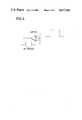
- FIG. 1is a schematic diagram of the fluorescent key concept of the present invention
- FIG. 2are waveforms illustrating the LED and photoreceptor actions of the photodiode of the present invention
- FIG. 3is a schematic illustration of the comparator amplifier and waveforms for the invention.
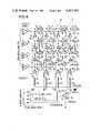
- FIG. 4is a diagrammatic illustration of a photo-optical keyboard in accordance with the present invention.
- FIG. 5is a schematic representation of a power supply for the keyboard implementation of the invention.
- FIG. 6illustrates the drive waveforms for the keyboard of the subject invention.
- FIGS. 7A, 7Bcomprise a combined functional schematic and associated waveforms for a row driver for the keyboard of the subject inventions.
- a switching device 10in accordance with the present invention, is seen to include a conventional photodiode 12 which is disposed adjacent to the movable portion, e.g., blade 14, of a keyboard key member 16.
- the confronting (facing) portion of blade 14is provided with a fluorescent light reflective surface 18 thereon.
- Diode 12is first forward biased, FIG. 1, so that the diode acts as a light emitting member (LED) when point ⁇ a is driven negative during time T 1 (FIG. 2). During this time node ⁇ b is also negative. During time T 2 , point ⁇ a is driven positive. Diode 12 is now reverse biased and acts as a photodiode detecting the light incident on surface 18.
- the key surface coating 18comprises a fluorescent material which has the property of retaining optical energy and gradually re-emitting this energy in the form of light as required.
- the construction in accordance with the present inventionminimizes the requirement for numerous photodiodes and photodetectors as well as simplifying the associated electronics effectively providing a noise-free switching apparatus.
- Fluorescent photo-optical keyboard apparatus 26conceived in accordance with the teaching of this invention is illustrated diagrammatically in more or less detail in FIGS. 4, 5 and 6, which will be described hereinafter.
- the keyboard 26comprises 16 fluorescent optical switching devices 10 arranged in a 4 ⁇ 4 array matrix (hex keyboard of 16 keys identified as 16).
- FIG. 5The power distribution is shown schematically in FIG. 5 and is intended to be self-explanatory as applied to the keyboard of FIG. 4. It is noted that FIG. 5 exemplifies an amplifier as designated A 3 in FIG. 4.
- the schematically illustrated keyboard of FIG. 4comprises an array of rows and columns of keys 16 arranged in the previously mentioned 4 ⁇ 4 matrix.
- Each key stem or blade 14carries a fluorescent coating 18 and is disposed adjacent to a respective opto-electronic component, e.g., a photodiode 12.
- the rows of keysare identified as K 0 through K f inclusive, while the diodes 12 are labeled D 0 through D f inclusive.
- the diodes 12are disposed in columns (as shown in FIG. 4) and are serially, electrically coupled to respective amplifiers identified as A 0 , A 1 , A 2 , and A 3 of electrical amplifier package 24.
- the negative poles of diodes 12are electrically serially connected to a respective row driver 28, each of which is capable of responding to three states of operation, as earlier described in connection with FIG. 1.
- the outputs of amplifiers A 0 through A 3are individually connected to an operably associated microcomputer over lines identified as Y 0 through Y 3 , respectively.
- Bias resistors 30are connected between the positive pole of each diode and the reference ground connection.
- diodes D 0 through D 3With the voltages and currents as shown in FIG. 5 and FIG. 6 when X 0 is driven "low", i.e., near system ground, diodes D 0 through D 3 become immediately forward biased and act as LEDs, emitting light. If any one of the keys (K 0 through K 3 ), 16 are actuated, i.e., depressed, fluorescent surface 18 is exposed to the light and stores optical energy for emission later on.
- X 0is pulled to a H 2 state so no signal can flow and the cycle is repeated for the keys in row X 1 .
- X 0is activated and V 2 and hence Y 2 is observed to be active high signal it amounts to key K 2 being activated which is common element for X 0 row and Y 2 column. This is illustrated in FIG. 4.
- K 0 . . . K 3 activationsdetermined when X 0 is activated.
- FIG. 6illustrates X 0 through X 3 waveforms during operation of the system.
- the microcomputereasily generates such a set of waveforms and accepts Y 0 through Y 3 signals and validates which key or keys have been actuated.
- the systemeffectively provides for N-key rollover while maintaining all other functions of conventional keyboards while simultaneously greatly reducing the number of relatively expensive components required for the system.
- Each rowis scanned, one at a time and Y 0 . . . Y 3 provide information about wich key or keys are deactivated.
- each keyhas unique identification code in terms of X signals and -Y- signals and can be identified uniquely. In case of multiple closure the keys are identified in scanning sequence. This is the property of -N- key rollover, which the present system has.
Landscapes
- Input From Keyboards Or The Like (AREA)
Abstract
Description
1. Field of the Invention
This invention relates generally to photo-optical keyboard apparatus and more specifically to the concept of utilizing a single photo-optical component as both a light generator and light detector in a matrix array for use, for example, in a keyboard.
2. Description of the Prior Art
The vast majority of presently available photo-optical keyboard constructions utilize multiple light generators and multiple light detectors. Usually, these components are arranged in rows and columns with the light generators disposed at the row positions and the light detectors disposed at the column positions or vice versa depending on the designer's choice.
This multiplicity of component assemblies is not only expensive but also complicated to assemble, maintain and operate as a result of the miniaturization involved. In addition, the printed wiring boards which are required for such apparatus are also expensive to produce due to the complex circuitry employed with the multiplicity of component assemblies.
The present invention is based upon the concept that a single component can be employed to perform two completely different though related functions. In the present instance, it has been discovered that one discrete electrical component, namely an optical-photo diode, is capable of functioning both as a light generating device as well as a light detecting device by means of suitable electronic circuitry. By coating the movable portion of a key switch (blade) with fluorescent material and arranging the key blade adjacent to the active portion of a common photo-diode, the photo-diode through suitable biasing can be caused to first emit light and then to detect the reflected light emitted by the fluorescent material on the key blade. Thus by moving the key under finger pressure, for example, the light emitted by the LED causes fluorescence in the material which persists long enough to be detected by the LED when it is later biased as a detector. The light is caused to be reflected back onto the diode which now acts as a photoreceptor due to the timed change in bias producing an output signal indicating that the switch has been activated or closed.
By arranging a plurality of fluorescent optical key switches in an array matrix of rows and columns, a low-cost, photo-optical keyboard has been conceived. The electronics involved is fairly straightforward and inexpensive and provides a keyboard with N-key rollover as well as the typical keyboard features of conventional keyboards but with the greatly reduced component complexity while increasing component and system reliability. The construction is capable of operating at very low voltage and current levels which in turn reduces the heat generated while tending to increase overall reliability of the system.
FIG. 1 is a schematic diagram of the fluorescent key concept of the present invention;
FIG. 2 are waveforms illustrating the LED and photoreceptor actions of the photodiode of the present invention;
FIG. 3 is a schematic illustration of the comparator amplifier and waveforms for the invention;
FIG. 4 is a diagrammatic illustration of a photo-optical keyboard in accordance with the present invention;
FIG. 5 is a schematic representation of a power supply for the keyboard implementation of the invention; and
FIG. 6 illustrates the drive waveforms for the keyboard of the subject invention.
FIGS. 7A, 7B comprise a combined functional schematic and associated waveforms for a row driver for the keyboard of the subject inventions.
In order to minimize the number of light generating and receiving devices, e.g., LEDs and photodetectors, it has been proposed to employ the same physical component both as a light emitter as well as a light detector in a switching mechanism. It is further proposed to provide a keyboard array utilizing these same components in a matrix arrangement effectively reducing the number of previously required separate light generators and detectors.
As shown in the highly diagrammatic schematic illustration of FIG. 1, aswitching device 10 in accordance with the present invention, is seen to include aconventional photodiode 12 which is disposed adjacent to the movable portion, e.g.,blade 14, of akeyboard key member 16. The confronting (facing) portion ofblade 14 is provided with a fluorescent lightreflective surface 18 thereon.
In the "up" or inactive position ofswitch 10, thelight rays 20 exiting fromLED 12 are ineffective since thereflective surface 18 is out of position relative to the active portion of the LED. However, in the "down" or active position ofswitch 10, thelight rays 20 are reflected back from thefluorescent surface 18 onto the active surface of thediode 12.
With key 16 in the "up" or inactive position (not pressed), no light will be incident uponsurface 18 and there will be no light retention. Point ○b will be near 0 volts as seen in Section I of FIG. 2 (trace 2).
Whenkey 16 is depressed or activated to the "down" position, during time T1 (whendiode 10 is acting as an LED), light from the diode strikes thefluorescent surface 18 ofkey 16 and optical energy is voluntarily retained by the surface. During time T2, (Section II of the diagram), this surface becomes a light emitter and the emittedrays 20 now strike thediode 12 which acts as a photodiode. This action causes a photocurrent I to flow throughdiode 12 generating a positive going signal at ○b as seen at T2 in FIG. 2, (Section II). This signal signifies thatkey 16 has been activated or pressed "down". Processing this signal through anelectrical amplifier 24 provides a clean logic signal at ○c FIG. 2, as shown at Section II T2. The optical retentivity of thefluorescent material coating 18 should last for a minimum of a few milliseconds in order to give a conclusive (positive) light output during interval T2 Section II.
The construction in accordance with the present invention minimizes the requirement for numerous photodiodes and photodetectors as well as simplifying the associated electronics effectively providing a noise-free switching apparatus.
Fluorescent photo-optical keyboard apparatus 26 conceived in accordance with the teaching of this invention is illustrated diagrammatically in more or less detail in FIGS. 4, 5 and 6, which will be described hereinafter.
As seen first in FIG. 4, thekeyboard 26 comprises 16 fluorescentoptical switching devices 10 arranged in a 4×4 array matrix (hex keyboard of 16 keys identified as 16).
The power distribution is shown schematically in FIG. 5 and is intended to be self-explanatory as applied to the keyboard of FIG. 4. It is noted that FIG. 5 exemplifies an amplifier as designated A3 in FIG. 4.
The schematically illustrated keyboard of FIG. 4 comprises an array of rows and columns ofkeys 16 arranged in the previously mentioned 4×4 matrix. Each key stem orblade 14 carries afluorescent coating 18 and is disposed adjacent to a respective opto-electronic component, e.g., aphotodiode 12. The rows of keys are identified as K0 through Kf inclusive, while thediodes 12 are labeled D0 through Df inclusive.
Thediodes 12 are disposed in columns (as shown in FIG. 4) and are serially, electrically coupled to respective amplifiers identified as A0, A1, A2, and A3 ofelectrical amplifier package 24. The negative poles ofdiodes 12 are electrically serially connected to arespective row driver 28, each of which is capable of responding to three states of operation, as earlier described in connection with FIG. 1.
The outputs of amplifiers A0 through A3 are individually connected to an operably associated microcomputer over lines identified as Y0 through Y3, respectively.Bias resistors 30 are connected between the positive pole of each diode and the reference ground connection.
With the voltages and currents as shown in FIG. 5 and FIG. 6 when X0 is driven "low", i.e., near system ground, diodes D0 through D3 become immediately forward biased and act as LEDs, emitting light. If any one of the keys (K0 through K3), 16 are actuated, i.e., depressed,fluorescent surface 18 is exposed to the light and stores optical energy for emission later on.
When X0 is driven high (near Vcc, substantially equal to 5 volts) D0 through D3 become reverse biased and act as photodiodes. The light emitted by any key surface now actuated (which has been exposed before and is now storing optical energy), strikes thecorresponding diode 12 producing a photocurrent through this latter member. This causes the corresponding voltages V0 through V3 to go more positive than the reference voltage VR, which in turn causes the system output lines Y0 through Y3 to go high (refer to FIG. 4). By observing the relationship between X and Y signals, it then becomes possible to identify the key being actuated. Any signals on output lines Y0 through Y3 indicates those keys in row X0 were depressed. To scan row X1, X0 is pulled to a H2 state so no signal can flow and the cycle is repeated for the keys in row X1. For example if X0 is activated and V2 and hence Y2 is observed to be active high signal it amounts to key K2 being activated which is common element for X0 row and Y2 column. This is illustrated in FIG. 4. Thus K0 . . . K3 activations determined when X0 is activated.
When X0 is pulled to a Hz (high impedance) state,Row 0 is effectively disconnected. By activating X1, it is possible to determine K4 through K7 key actuations, and so on.
The complete scanning of the keyboard is accomplished by sequentially actuating row drivers for X0 through X3 and observing Y0 through Y3. It is noted that actuations of X signifies the steps of pulling it first low, then high and finally into its tri-state (3rd state).
FIG. 6 illustrates X0 through X3 waveforms during operation of the system. The microcomputer easily generates such a set of waveforms and accepts Y0 through Y3 signals and validates which key or keys have been actuated.
Thus, if Y0 through Y3 =0100 during X0 at high level, this signals that key K1 is actuated. On the other hand, if Y0 through Y3 =1100 when X2 is activated, this signals two keys KC and KD have been actuated. The microprocessor will generate a logic low or high on a data line, connected to the input of a tri-state bus driver device such as SN 4LS241. Also it will generate a tri-state control signal. The composite effect is a waveform similar to -X0 -, as shown in FIGS. 7A and 7B.
Thus, the system effectively provides for N-key rollover while maintaining all other functions of conventional keyboards while simultaneously greatly reducing the number of relatively expensive components required for the system. Each row is scanned, one at a time and Y0 . . . Y3 provide information about wich key or keys are deactivated. Thus, each key has unique identification code in terms of X signals and -Y- signals and can be identified uniquely. In case of multiple closure the keys are identified in scanning sequence. This is the property of -N- key rollover, which the present system has.
Claims (7)
1. Fluorescent optical switch and keyboard apparatus comprising:
photo-optical means adapted to operate in a light emitting, a light receiving and a passive mode,
fluorescent means disposed adjacent to said photo-optical means and capable of movement from a light blocking to a light passing position, and
circuit means interconnected to said photo-optical means for energizing said photo-optical means to a level causing said photo-optical means to emit light for impingement upon said fluorescent means when said fluorescent means is disposed in a light fluorescent position, said circuit means thereafter biasing said photo-optical means so as to cause said photo-optical means to act as a light receptor and to generate an electrical signal output indicating the actuation of the device.
2. The combination according to claim 1 wherein said photo-optical means further comprises a photo-diode.
3. The combination according to claim 1 wherein said fluorescent means is carried by the key stem of a photo-optical keyboard.
4. The combination according to claim 1 wherein said fluorescent means comprises a fluorescent coating on a support structure.
5. Fluorescent optical switch and keyboard apparatus comprising:
a matrix array of rows and columns of keys arranged to form a keyboard,
a photo-diode disposed adjacent to the key stem of each key,
a fluorescent material having a delay time commensurate with the response time of said photo-diode coated on one portion of said key stem,
electrical circuit means for biasing said photo-diode first in a forward direction so as to cause the diode to emit light for impingement upon the fluorescent material and for then biasing said photo-diode in the reverse direction causing said diode to act as a light receptor, and
microprocessor means for controlling the electrical signals input to and output from said photo-diode effective to indicate key actuation.
6. The combination according to claim 5 further including a row driver for each row of photo-diode and being capable of responding to three discrete states of operation of said diodes.
7. The combination according to claim 5 wherein said microprocessor means further includes a separate amplifier for each column of photo-diode.
Priority Applications (1)
| Application Number | Priority Date | Filing Date | Title |
|---|---|---|---|
| US06/603,876US4617461A (en) | 1984-04-25 | 1984-04-25 | Fluorescent optical switch and keyboard apparatus |
Applications Claiming Priority (1)
| Application Number | Priority Date | Filing Date | Title |
|---|---|---|---|
| US06/603,876US4617461A (en) | 1984-04-25 | 1984-04-25 | Fluorescent optical switch and keyboard apparatus |
Publications (1)
| Publication Number | Publication Date |
|---|---|
| US4617461Atrue US4617461A (en) | 1986-10-14 |
Family
ID=24417289
Family Applications (1)
| Application Number | Title | Priority Date | Filing Date |
|---|---|---|---|
| US06/603,876Expired - Fee RelatedUS4617461A (en) | 1984-04-25 | 1984-04-25 | Fluorescent optical switch and keyboard apparatus |
Country Status (1)
| Country | Link |
|---|---|
| US (1) | US4617461A (en) |
Cited By (50)
| Publication number | Priority date | Publication date | Assignee | Title |
|---|---|---|---|---|
| US4692612A (en)* | 1986-06-13 | 1987-09-08 | Karel Havel | Switch position detector and indicator with multicolor light emitter |
| US4795900A (en)* | 1986-03-27 | 1989-01-03 | Sadao Kokubu | Optical switch device employing a fluorescent substance with a radioactive element as a light source |
| US4806908A (en)* | 1987-05-14 | 1989-02-21 | Astronics Corporation | Low profile backlighted keyboard |
| US4847508A (en)* | 1986-03-27 | 1989-07-11 | Sadao Kokubu | Photo-coupler switch with delay function using a fluorescent substance as the delay means |
| US4868384A (en)* | 1987-08-04 | 1989-09-19 | Josef Franken | Electric pressure switch |
| US4878722A (en)* | 1988-06-24 | 1989-11-07 | Korry Electronics Company | Wavelength encoded optical switches |
| US6322229B1 (en) | 1998-11-13 | 2001-11-27 | Questech International, Inc. | Backlighting for computer keyboard |
| WO2001067160A3 (en)* | 2000-03-10 | 2002-01-03 | Tidal Photonics Inc | Apparatus and methods relating to fluorescent optical switches |
| US20030137338A1 (en)* | 2000-12-25 | 2003-07-24 | Toshiyuki Hisatsune | Electronic apparatus |
| US6765503B1 (en) | 1998-11-13 | 2004-07-20 | Lightpath Technologies, Inc. | Backlighting for computer keyboard |
| US6871978B2 (en) | 1998-11-13 | 2005-03-29 | Lightpath Technologies, Inc. | Computer keyboard backlighting |
| US20050104846A1 (en)* | 2003-11-19 | 2005-05-19 | Adapathya Ravi S. | Apparatus, system, and process for demarking control objects using direct non-visible light |
| US20050184885A1 (en)* | 2004-02-24 | 2005-08-25 | Nokia Corporation | Optical keyboard with geodesic optical elements |
| US20060011461A1 (en)* | 1998-11-13 | 2006-01-19 | Chan Sam E J | Computer keyboard backlighting |
| US20080212307A1 (en)* | 1998-11-13 | 2008-09-04 | Chan Sam E J | Computer keyboard backlighting |
| US20090091478A1 (en)* | 1998-11-13 | 2009-04-09 | Chan Sam E J | Computer keyboard backlighting |
| US7855715B1 (en)* | 2005-07-27 | 2010-12-21 | James Harrison Bowen | Switch with depth and lateral articulation detection using optical beam |
| US9395822B2 (en) | 2014-03-03 | 2016-07-19 | Peter Hinz | Keycap including a liquid crystal panel and polarizing glyphs |
| US9542016B2 (en) | 2012-09-13 | 2017-01-10 | Apple Inc. | Optical sensing mechanisms for input devices |
| US9709956B1 (en) | 2013-08-09 | 2017-07-18 | Apple Inc. | Tactile switch for an electronic device |
| US9753436B2 (en) | 2013-06-11 | 2017-09-05 | Apple Inc. | Rotary input mechanism for an electronic device |
| US9797752B1 (en) | 2014-07-16 | 2017-10-24 | Apple Inc. | Optical encoder with axially aligned sensor |
| US9797753B1 (en) | 2014-08-27 | 2017-10-24 | Apple Inc. | Spatial phase estimation for optical encoders |
| US9891651B2 (en) | 2016-02-27 | 2018-02-13 | Apple Inc. | Rotatable input mechanism having adjustable output |
| US9952682B2 (en) | 2015-04-15 | 2018-04-24 | Apple Inc. | Depressible keys with decoupled electrical and mechanical functionality |
| US9952558B2 (en) | 2015-03-08 | 2018-04-24 | Apple Inc. | Compressible seal for rotatable and translatable input mechanisms |
| US10019097B2 (en) | 2016-07-25 | 2018-07-10 | Apple Inc. | Force-detecting input structure |
| US10018966B2 (en) | 2015-04-24 | 2018-07-10 | Apple Inc. | Cover member for an input mechanism of an electronic device |
| US10048802B2 (en) | 2014-02-12 | 2018-08-14 | Apple Inc. | Rejection of false turns of rotary inputs for electronic devices |
| US10061399B2 (en) | 2016-07-15 | 2018-08-28 | Apple Inc. | Capacitive gap sensor ring for an input device |
| US10066970B2 (en) | 2014-08-27 | 2018-09-04 | Apple Inc. | Dynamic range control for optical encoders |
| US10145711B2 (en) | 2015-03-05 | 2018-12-04 | Apple Inc. | Optical encoder with direction-dependent optical properties having an optically anisotropic region to produce a first and a second light distribution |
| US10190891B1 (en) | 2014-07-16 | 2019-01-29 | Apple Inc. | Optical encoder for detecting rotational and axial movement |
| US10551798B1 (en) | 2016-05-17 | 2020-02-04 | Apple Inc. | Rotatable crown for an electronic device |
| US10599101B2 (en) | 2014-09-02 | 2020-03-24 | Apple Inc. | Wearable electronic device |
| US10664074B2 (en) | 2017-06-19 | 2020-05-26 | Apple Inc. | Contact-sensitive crown for an electronic watch |
| US10962935B1 (en) | 2017-07-18 | 2021-03-30 | Apple Inc. | Tri-axis force sensor |
| US11011328B2 (en)* | 2019-06-18 | 2021-05-18 | Lite-On Electronics (Guangzhou) Limited | Key module, keyboard and electronic device using same |
| US11181863B2 (en) | 2018-08-24 | 2021-11-23 | Apple Inc. | Conductive cap for watch crown |
| US11194298B2 (en) | 2018-08-30 | 2021-12-07 | Apple Inc. | Crown assembly for an electronic watch |
| US11194299B1 (en) | 2019-02-12 | 2021-12-07 | Apple Inc. | Variable frictional feedback device for a digital crown of an electronic watch |
| US11269376B2 (en) | 2020-06-11 | 2022-03-08 | Apple Inc. | Electronic device |
| US11360440B2 (en) | 2018-06-25 | 2022-06-14 | Apple Inc. | Crown for an electronic watch |
| US11550268B2 (en) | 2020-06-02 | 2023-01-10 | Apple Inc. | Switch module for electronic crown assembly |
| US11561515B2 (en) | 2018-08-02 | 2023-01-24 | Apple Inc. | Crown for an electronic watch |
| US11796968B2 (en) | 2018-08-30 | 2023-10-24 | Apple Inc. | Crown assembly for an electronic watch |
| US11796961B2 (en) | 2018-08-24 | 2023-10-24 | Apple Inc. | Conductive cap for watch crown |
| US12092996B2 (en) | 2021-07-16 | 2024-09-17 | Apple Inc. | Laser-based rotation sensor for a crown of an electronic watch |
| US12189347B2 (en) | 2022-06-14 | 2025-01-07 | Apple Inc. | Rotation sensor for a crown of an electronic watch |
| US12259690B2 (en) | 2018-08-24 | 2025-03-25 | Apple Inc. | Watch crown having a conductive surface |
Citations (2)
| Publication number | Priority date | Publication date | Assignee | Title |
|---|---|---|---|---|
| US4379968A (en)* | 1980-12-24 | 1983-04-12 | Burroughs Corp. | Photo-optical keyboard having light attenuating means |
| US4480182A (en)* | 1982-03-16 | 1984-10-30 | Burroughs Corporation | Single plane optical membrane switch and keyboard |
- 1984
- 1984-04-25USUS06/603,876patent/US4617461A/ennot_activeExpired - Fee Related
Patent Citations (2)
| Publication number | Priority date | Publication date | Assignee | Title |
|---|---|---|---|---|
| US4379968A (en)* | 1980-12-24 | 1983-04-12 | Burroughs Corp. | Photo-optical keyboard having light attenuating means |
| US4480182A (en)* | 1982-03-16 | 1984-10-30 | Burroughs Corporation | Single plane optical membrane switch and keyboard |
Cited By (121)
| Publication number | Priority date | Publication date | Assignee | Title |
|---|---|---|---|---|
| US4795900A (en)* | 1986-03-27 | 1989-01-03 | Sadao Kokubu | Optical switch device employing a fluorescent substance with a radioactive element as a light source |
| US4847508A (en)* | 1986-03-27 | 1989-07-11 | Sadao Kokubu | Photo-coupler switch with delay function using a fluorescent substance as the delay means |
| US4692612A (en)* | 1986-06-13 | 1987-09-08 | Karel Havel | Switch position detector and indicator with multicolor light emitter |
| US4806908A (en)* | 1987-05-14 | 1989-02-21 | Astronics Corporation | Low profile backlighted keyboard |
| US4868384A (en)* | 1987-08-04 | 1989-09-19 | Josef Franken | Electric pressure switch |
| US4878722A (en)* | 1988-06-24 | 1989-11-07 | Korry Electronics Company | Wavelength encoded optical switches |
| US6322229B1 (en) | 1998-11-13 | 2001-11-27 | Questech International, Inc. | Backlighting for computer keyboard |
| US20060011461A1 (en)* | 1998-11-13 | 2006-01-19 | Chan Sam E J | Computer keyboard backlighting |
| US20090091478A1 (en)* | 1998-11-13 | 2009-04-09 | Chan Sam E J | Computer keyboard backlighting |
| US20080212307A1 (en)* | 1998-11-13 | 2008-09-04 | Chan Sam E J | Computer keyboard backlighting |
| US6765503B1 (en) | 1998-11-13 | 2004-07-20 | Lightpath Technologies, Inc. | Backlighting for computer keyboard |
| US6871978B2 (en) | 1998-11-13 | 2005-03-29 | Lightpath Technologies, Inc. | Computer keyboard backlighting |
| US20050083214A1 (en)* | 1998-11-13 | 2005-04-21 | Chan Sam E.J. | Backlighting for computer keyboard |
| US7335843B2 (en) | 1998-11-13 | 2008-02-26 | Firefly International, Inc. | Computer keyboard backlighting |
| WO2001067160A3 (en)* | 2000-03-10 | 2002-01-03 | Tidal Photonics Inc | Apparatus and methods relating to fluorescent optical switches |
| US20050145802A1 (en)* | 2000-03-10 | 2005-07-07 | Mackinnon Nicholas B. | Apparatus and methods relating to fluorescent optical switches |
| US6721471B2 (en) | 2000-03-10 | 2004-04-13 | Tidal Photonics, Inc. | Apparatus and methods relating to fluorescent optical switches |
| US7224307B2 (en)* | 2000-12-25 | 2007-05-29 | Sony Corporation | Electronic device |
| US20030137338A1 (en)* | 2000-12-25 | 2003-07-24 | Toshiyuki Hisatsune | Electronic apparatus |
| US20050104846A1 (en)* | 2003-11-19 | 2005-05-19 | Adapathya Ravi S. | Apparatus, system, and process for demarking control objects using direct non-visible light |
| US20050184885A1 (en)* | 2004-02-24 | 2005-08-25 | Nokia Corporation | Optical keyboard with geodesic optical elements |
| US7042371B2 (en)* | 2004-02-24 | 2006-05-09 | Nokia Corporation | Optical keyboard with geodesic optical elements |
| US20110026997A1 (en)* | 2005-07-27 | 2011-02-03 | Bowen James H | Switch with Depth and Lateral Articulation Detection |
| US7855715B1 (en)* | 2005-07-27 | 2010-12-21 | James Harrison Bowen | Switch with depth and lateral articulation detection using optical beam |
| US7982716B2 (en)* | 2005-07-27 | 2011-07-19 | Bowen James H | Switch with depth and lateral articulation detection |
| US9542016B2 (en) | 2012-09-13 | 2017-01-10 | Apple Inc. | Optical sensing mechanisms for input devices |
| US9857892B2 (en) | 2012-09-13 | 2018-01-02 | Apple Inc. | Optical sensing mechanisms for input devices |
| US10234828B2 (en) | 2013-06-11 | 2019-03-19 | Apple Inc. | Rotary input mechanism for an electronic device |
| US9753436B2 (en) | 2013-06-11 | 2017-09-05 | Apple Inc. | Rotary input mechanism for an electronic device |
| US11531306B2 (en) | 2013-06-11 | 2022-12-20 | Apple Inc. | Rotary input mechanism for an electronic device |
| US9886006B2 (en) | 2013-06-11 | 2018-02-06 | Apple Inc. | Rotary input mechanism for an electronic device |
| US9709956B1 (en) | 2013-08-09 | 2017-07-18 | Apple Inc. | Tactile switch for an electronic device |
| US10331081B2 (en) | 2013-08-09 | 2019-06-25 | Apple Inc. | Tactile switch for an electronic device |
| US10962930B2 (en) | 2013-08-09 | 2021-03-30 | Apple Inc. | Tactile switch for an electronic device |
| US10216147B2 (en) | 2013-08-09 | 2019-02-26 | Apple Inc. | Tactile switch for an electronic device |
| US12181840B2 (en) | 2013-08-09 | 2024-12-31 | Apple Inc. | Tactile switch for an electronic device |
| US10175652B2 (en) | 2013-08-09 | 2019-01-08 | Apple Inc. | Tactile switch for an electronic device |
| US9971305B2 (en) | 2013-08-09 | 2018-05-15 | Apple Inc. | Tactile switch for an electronic device |
| US11886149B2 (en) | 2013-08-09 | 2024-01-30 | Apple Inc. | Tactile switch for an electronic device |
| US9836025B2 (en) | 2013-08-09 | 2017-12-05 | Apple Inc. | Tactile switch for an electronic device |
| US10732571B2 (en) | 2013-08-09 | 2020-08-04 | Apple Inc. | Tactile switch for an electronic device |
| US10331082B2 (en) | 2013-08-09 | 2019-06-25 | Apple Inc. | Tactile switch for an electronic device |
| US11347351B2 (en) | 2014-02-12 | 2022-05-31 | Apple Inc. | Rejection of false turns of rotary inputs for electronic devices |
| US10048802B2 (en) | 2014-02-12 | 2018-08-14 | Apple Inc. | Rejection of false turns of rotary inputs for electronic devices |
| US11669205B2 (en) | 2014-02-12 | 2023-06-06 | Apple Inc. | Rejection of false turns of rotary inputs for electronic devices |
| US12045416B2 (en) | 2014-02-12 | 2024-07-23 | Apple Inc. | Rejection of false turns of rotary inputs for electronic devices |
| US10884549B2 (en) | 2014-02-12 | 2021-01-05 | Apple Inc. | Rejection of false turns of rotary inputs for electronic devices |
| US12307047B2 (en) | 2014-02-12 | 2025-05-20 | Apple Inc. | Rejection of false turns of rotary inputs for electronic devices |
| US10613685B2 (en) | 2014-02-12 | 2020-04-07 | Apple Inc. | Rejection of false turns of rotary inputs for electronic devices |
| US10222909B2 (en) | 2014-02-12 | 2019-03-05 | Apple Inc. | Rejection of false turns of rotary inputs for electronic devices |
| US9395822B2 (en) | 2014-03-03 | 2016-07-19 | Peter Hinz | Keycap including a liquid crystal panel and polarizing glyphs |
| US10190891B1 (en) | 2014-07-16 | 2019-01-29 | Apple Inc. | Optical encoder for detecting rotational and axial movement |
| US11015960B2 (en) | 2014-07-16 | 2021-05-25 | Apple Inc. | Optical encoder for detecting crown movement |
| US9797752B1 (en) | 2014-07-16 | 2017-10-24 | Apple Inc. | Optical encoder with axially aligned sensor |
| US10533879B2 (en) | 2014-07-16 | 2020-01-14 | Apple Inc. | Optical encoder with axially aligned sensor |
| US10066970B2 (en) | 2014-08-27 | 2018-09-04 | Apple Inc. | Dynamic range control for optical encoders |
| US9797753B1 (en) | 2014-08-27 | 2017-10-24 | Apple Inc. | Spatial phase estimation for optical encoders |
| US10599101B2 (en) | 2014-09-02 | 2020-03-24 | Apple Inc. | Wearable electronic device |
| US10942491B2 (en) | 2014-09-02 | 2021-03-09 | Apple Inc. | Wearable electronic device |
| US11474483B2 (en) | 2014-09-02 | 2022-10-18 | Apple Inc. | Wearable electronic device |
| US11567457B2 (en) | 2014-09-02 | 2023-01-31 | Apple Inc. | Wearable electronic device |
| US10613485B2 (en) | 2014-09-02 | 2020-04-07 | Apple Inc. | Wearable electronic device |
| US10620591B2 (en) | 2014-09-02 | 2020-04-14 | Apple Inc. | Wearable electronic device |
| US10627783B2 (en) | 2014-09-02 | 2020-04-21 | Apple Inc. | Wearable electronic device |
| US11762342B2 (en) | 2014-09-02 | 2023-09-19 | Apple Inc. | Wearable electronic device |
| US11221590B2 (en) | 2014-09-02 | 2022-01-11 | Apple Inc. | Wearable electronic device |
| US10145711B2 (en) | 2015-03-05 | 2018-12-04 | Apple Inc. | Optical encoder with direction-dependent optical properties having an optically anisotropic region to produce a first and a second light distribution |
| US10655988B2 (en) | 2015-03-05 | 2020-05-19 | Apple Inc. | Watch with rotatable optical encoder having a spindle defining an array of alternating regions extending along an axial direction parallel to the axis of a shaft |
| US11002572B2 (en) | 2015-03-05 | 2021-05-11 | Apple Inc. | Optical encoder with direction-dependent optical properties comprising a spindle having an array of surface features defining a concave contour along a first direction and a convex contour along a second direction |
| US10845764B2 (en) | 2015-03-08 | 2020-11-24 | Apple Inc. | Compressible seal for rotatable and translatable input mechanisms |
| US9952558B2 (en) | 2015-03-08 | 2018-04-24 | Apple Inc. | Compressible seal for rotatable and translatable input mechanisms |
| US11988995B2 (en) | 2015-03-08 | 2024-05-21 | Apple Inc. | Compressible seal for rotatable and translatable input mechanisms |
| US10037006B2 (en) | 2015-03-08 | 2018-07-31 | Apple Inc. | Compressible seal for rotatable and translatable input mechanisms |
| US9952682B2 (en) | 2015-04-15 | 2018-04-24 | Apple Inc. | Depressible keys with decoupled electrical and mechanical functionality |
| US10018966B2 (en) | 2015-04-24 | 2018-07-10 | Apple Inc. | Cover member for an input mechanism of an electronic device |
| US10222756B2 (en) | 2015-04-24 | 2019-03-05 | Apple Inc. | Cover member for an input mechanism of an electronic device |
| US9891651B2 (en) | 2016-02-27 | 2018-02-13 | Apple Inc. | Rotatable input mechanism having adjustable output |
| US10579090B2 (en) | 2016-02-27 | 2020-03-03 | Apple Inc. | Rotatable input mechanism having adjustable output |
| US12104929B2 (en) | 2016-05-17 | 2024-10-01 | Apple Inc. | Rotatable crown for an electronic device |
| US10551798B1 (en) | 2016-05-17 | 2020-02-04 | Apple Inc. | Rotatable crown for an electronic device |
| US11513613B2 (en) | 2016-07-15 | 2022-11-29 | Apple Inc. | Capacitive gap sensor ring for an input device |
| US10509486B2 (en) | 2016-07-15 | 2019-12-17 | Apple Inc. | Capacitive gap sensor ring for an electronic watch |
| US10061399B2 (en) | 2016-07-15 | 2018-08-28 | Apple Inc. | Capacitive gap sensor ring for an input device |
| US10955937B2 (en) | 2016-07-15 | 2021-03-23 | Apple Inc. | Capacitive gap sensor ring for an input device |
| US10379629B2 (en) | 2016-07-15 | 2019-08-13 | Apple Inc. | Capacitive gap sensor ring for an electronic watch |
| US12086331B2 (en) | 2016-07-15 | 2024-09-10 | Apple Inc. | Capacitive gap sensor ring for an input device |
| US11720064B2 (en) | 2016-07-25 | 2023-08-08 | Apple Inc. | Force-detecting input structure |
| US11385599B2 (en) | 2016-07-25 | 2022-07-12 | Apple Inc. | Force-detecting input structure |
| US12105479B2 (en) | 2016-07-25 | 2024-10-01 | Apple Inc. | Force-detecting input structure |
| US10572053B2 (en) | 2016-07-25 | 2020-02-25 | Apple Inc. | Force-detecting input structure |
| US10019097B2 (en) | 2016-07-25 | 2018-07-10 | Apple Inc. | Force-detecting input structure |
| US10296125B2 (en) | 2016-07-25 | 2019-05-21 | Apple Inc. | Force-detecting input structure |
| US10948880B2 (en) | 2016-07-25 | 2021-03-16 | Apple Inc. | Force-detecting input structure |
| US10664074B2 (en) | 2017-06-19 | 2020-05-26 | Apple Inc. | Contact-sensitive crown for an electronic watch |
| US10962935B1 (en) | 2017-07-18 | 2021-03-30 | Apple Inc. | Tri-axis force sensor |
| US12066795B2 (en) | 2017-07-18 | 2024-08-20 | Apple Inc. | Tri-axis force sensor |
| US12105480B2 (en) | 2018-06-25 | 2024-10-01 | Apple Inc. | Crown for an electronic watch |
| US11360440B2 (en) | 2018-06-25 | 2022-06-14 | Apple Inc. | Crown for an electronic watch |
| US11754981B2 (en) | 2018-06-25 | 2023-09-12 | Apple Inc. | Crown for an electronic watch |
| US11906937B2 (en) | 2018-08-02 | 2024-02-20 | Apple Inc. | Crown for an electronic watch |
| US12282302B2 (en) | 2018-08-02 | 2025-04-22 | Apple Inc. | Crown for an electronic watch |
| US11561515B2 (en) | 2018-08-02 | 2023-01-24 | Apple Inc. | Crown for an electronic watch |
| US12259690B2 (en) | 2018-08-24 | 2025-03-25 | Apple Inc. | Watch crown having a conductive surface |
| US11181863B2 (en) | 2018-08-24 | 2021-11-23 | Apple Inc. | Conductive cap for watch crown |
| US11796961B2 (en) | 2018-08-24 | 2023-10-24 | Apple Inc. | Conductive cap for watch crown |
| US12276943B2 (en) | 2018-08-24 | 2025-04-15 | Apple Inc. | Conductive cap for watch crown |
| US12326697B2 (en) | 2018-08-30 | 2025-06-10 | Apple Inc. | Crown assembly for an electronic watch |
| US11796968B2 (en) | 2018-08-30 | 2023-10-24 | Apple Inc. | Crown assembly for an electronic watch |
| US11194298B2 (en) | 2018-08-30 | 2021-12-07 | Apple Inc. | Crown assembly for an electronic watch |
| US11194299B1 (en) | 2019-02-12 | 2021-12-07 | Apple Inc. | Variable frictional feedback device for a digital crown of an electronic watch |
| US11860587B2 (en) | 2019-02-12 | 2024-01-02 | Apple Inc. | Variable frictional feedback device for a digital crown of an electronic watch |
| US12346070B2 (en) | 2019-02-12 | 2025-07-01 | Apple Inc. | Variable frictional feedback device for a digital crown of an electronic watch |
| US11011328B2 (en)* | 2019-06-18 | 2021-05-18 | Lite-On Electronics (Guangzhou) Limited | Key module, keyboard and electronic device using same |
| US11815860B2 (en) | 2020-06-02 | 2023-11-14 | Apple Inc. | Switch module for electronic crown assembly |
| US12189342B2 (en) | 2020-06-02 | 2025-01-07 | Apple Inc. | Switch module for electronic crown assembly |
| US11550268B2 (en) | 2020-06-02 | 2023-01-10 | Apple Inc. | Switch module for electronic crown assembly |
| US11983035B2 (en) | 2020-06-11 | 2024-05-14 | Apple Inc. | Electronic device |
| US11269376B2 (en) | 2020-06-11 | 2022-03-08 | Apple Inc. | Electronic device |
| US11635786B2 (en) | 2020-06-11 | 2023-04-25 | Apple Inc. | Electronic optical sensing device |
| US12092996B2 (en) | 2021-07-16 | 2024-09-17 | Apple Inc. | Laser-based rotation sensor for a crown of an electronic watch |
| US12189347B2 (en) | 2022-06-14 | 2025-01-07 | Apple Inc. | Rotation sensor for a crown of an electronic watch |
Similar Documents
| Publication | Publication Date | Title |
|---|---|---|
| US4617461A (en) | Fluorescent optical switch and keyboard apparatus | |
| US5550856A (en) | Electro-optical device | |
| US20130271428A1 (en) | Scanning of a touch screen | |
| US20030201956A1 (en) | Image display | |
| TWI678716B (en) | Optical axis keyboard | |
| US4999688A (en) | Optical logic element with short switching time | |
| US4739163A (en) | Position locating optical coder utilizing optical fiber | |
| GB2178166A (en) | Optical coordinate input device | |
| CN111464167B (en) | Electronic device with non-contact intelligent key and control method thereof | |
| JPS61194784A (en) | optical object detection circuit | |
| US5321252A (en) | Improved driver circuitry for multiple sensors | |
| US4596984A (en) | Digital data input circuit | |
| JP2980288B2 (en) | Light detection device | |
| JP2558115B2 (en) | Camera barrel position detection device | |
| JPH1021008A (en) | Optical touch switch device | |
| US4950882A (en) | Opto-electrical exclusive or logic gates | |
| JPH09181673A (en) | Infrared communication device | |
| SU984039A1 (en) | Voltage-to-code converter | |
| JPH0648886Y2 (en) | Photo-interrupter | |
| SU1046939A1 (en) | Optoelectronic module | |
| JPH01165222A (en) | Driving circuit for semiconductor switching element | |
| JP2935823B2 (en) | Input/Output Devices | |
| JPS6245187A (en) | Image storage device | |
| JP3104390B2 (en) | Switch device with touch panel | |
| JPH0277824A (en) | Optical coordinate input device and its position indicator |
Legal Events
| Date | Code | Title | Description |
|---|---|---|---|
| AS | Assignment | Owner name:BURROUGHS CORPORATION, DETROIT, MI A MI CORP. Free format text:ASSIGNMENT OF ASSIGNORS INTEREST.;ASSIGNORS:SUBBARAO, WUNNAVA V.;ELY, RICHARD I.;REEL/FRAME:004254/0437 Effective date:19840413 | |
| AS | Assignment | Owner name:UNISYS CORPORATION, PENNSYLVANIA Free format text:MERGER;ASSIGNOR:BURROUGHS CORPORATION;REEL/FRAME:005012/0501 Effective date:19880509 | |
| FPAY | Fee payment | Year of fee payment:4 | |
| FEPP | Fee payment procedure | Free format text:PAYOR NUMBER ASSIGNED (ORIGINAL EVENT CODE: ASPN); ENTITY STATUS OF PATENT OWNER: LARGE ENTITY | |
| FPAY | Fee payment | Year of fee payment:8 | |
| REMI | Maintenance fee reminder mailed | ||
| LAPS | Lapse for failure to pay maintenance fees | ||
| FP | Lapsed due to failure to pay maintenance fee | Effective date:19981014 | |
| STCH | Information on status: patent discontinuation | Free format text:PATENT EXPIRED DUE TO NONPAYMENT OF MAINTENANCE FEES UNDER 37 CFR 1.362 |