US4617019A - Catheter - Google Patents
CatheterDownload PDFInfo
- Publication number
- US4617019A US4617019AUS06/655,853US65585384AUS4617019AUS 4617019 AUS4617019 AUS 4617019AUS 65585384 AUS65585384 AUS 65585384AUS 4617019 AUS4617019 AUS 4617019A
- Authority
- US
- United States
- Prior art keywords
- tubing
- distal end
- proximal
- wall portion
- end wall
- Prior art date
- Legal status (The legal status is an assumption and is not a legal conclusion. Google has not performed a legal analysis and makes no representation as to the accuracy of the status listed.)
- Expired - Lifetime
Links
Images


Classifications
- A—HUMAN NECESSITIES
- A61—MEDICAL OR VETERINARY SCIENCE; HYGIENE
- A61M—DEVICES FOR INTRODUCING MEDIA INTO, OR ONTO, THE BODY; DEVICES FOR TRANSDUCING BODY MEDIA OR FOR TAKING MEDIA FROM THE BODY; DEVICES FOR PRODUCING OR ENDING SLEEP OR STUPOR
- A61M25/00—Catheters; Hollow probes
- A61M25/0009—Making of catheters or other medical or surgical tubes
- A61M25/001—Forming the tip of a catheter, e.g. bevelling process, join or taper
- A—HUMAN NECESSITIES
- A61—MEDICAL OR VETERINARY SCIENCE; HYGIENE
- A61M—DEVICES FOR INTRODUCING MEDIA INTO, OR ONTO, THE BODY; DEVICES FOR TRANSDUCING BODY MEDIA OR FOR TAKING MEDIA FROM THE BODY; DEVICES FOR PRODUCING OR ENDING SLEEP OR STUPOR
- A61M25/00—Catheters; Hollow probes
- A61M25/0021—Catheters; Hollow probes characterised by the form of the tubing
- A—HUMAN NECESSITIES
- A61—MEDICAL OR VETERINARY SCIENCE; HYGIENE
- A61M—DEVICES FOR INTRODUCING MEDIA INTO, OR ONTO, THE BODY; DEVICES FOR TRANSDUCING BODY MEDIA OR FOR TAKING MEDIA FROM THE BODY; DEVICES FOR PRODUCING OR ENDING SLEEP OR STUPOR
- A61M25/00—Catheters; Hollow probes
- A61M25/0067—Catheters; Hollow probes characterised by the distal end, e.g. tips
- A61M25/0068—Static characteristics of the catheter tip, e.g. shape, atraumatic tip, curved tip or tip structure
- A61M25/007—Side holes, e.g. their profiles or arrangements; Provisions to keep side holes unblocked
Definitions
- This inventionrelates to catheters and more particularly to an intercostal catheter and to the method of making the same.
- intercostal cathetershave a distal end which may be inserted into the plural cavity of a patient for maintaining a negative pressure in the plural cavity where required and/or to remove wound drainage fluid from a wound or surgical incision to aid the healing process.
- an intercostal catheterhaving a funnel-like proximal end formed at an angle to the longitudinal axis of the tube and which has a point at the proximal tip.
- the distal endis a blunt end normal to the axis of the tube and is provided with a plurality of drainage openings in the sidewall adjacent the distal end.
- the proximal endmay serve as a tube connector for connecting tubing to a drainage collection system that may include a source of suction.
- the proximal endis generally inserted through the surgical incision and then pulled, such as with forceps, through a secondary incision to the exterior of the patient until the distal end moves into the desired location within the patient.
- the open proximal end of the cathetertends to close reducing damage to the patient.
- the proximal end of the cath teris formed in accordance with that patent by placing the tubing from which it is formed in a clamp, pressing the tube flat, and then cutting at the desired angle.
- an intercostal cathetercan be pinched, such as by forceps or by the fingers, and forced or tunneled from the exterior of the patient through an entrance incision, such as a stab wound or incision which passes between the ribs of the patient.
- a cathetermay be connected to a suction source to maintain the plural cavity at a negative pressure to allow the lung to expand for breathing and so that fluid can readily drain from the wound.
- the distal end of the catheterhas a blunt end or is formed normal to the longitudinal axis of the tube, and is squeezed by the fingers or by forceps and moved into the incision from the exterior of the patient
- the opposed sides of the substantially flattened endtend to increase in size and present a wide tube end extending normal to the tube axis.
- the cathetertends to tear or otherwise damage flesh during its movement through the incision into its desired location within the patient.
- undesirable protuberancesoccur when the distal end of the intercostal catheter is flattened during insertion.
- Trocar cathetershave also been used for closed-chest drainage.
- insertion of the catheter and pointed trocar into the patienthas the potential danger of damaging the patient, such as piercing the lung, as a result of the insertion technique.
- Another object of the present inventionis to provide an intercostal catheter having a distal end with a shape which when laterally compressed can be readily inserted into an incision of a patient from the exterior of the patient with minimal traumatic effects.
- Still another object of the present inventionis to provide an improved method of making a catheter of the above type.
- Still another object of the present inventionis to provide an intercostal catheter and method of making the same which substantially avoids one or more of the above mentioned problems or disadvantages associated with prior art devices.
- a method of making a catheterincludes the steps of severing flexible tubing including cutting the tubing at an angle to the longitudinal axis of the tubing to form a distal end wall that has a distal tip, and a proximal end wall portion inclined radially inwardly. A part of the proximal wall portion is displaced to substantially prevent the proximal wall portion from extending distally beyond the outer edge of the end wall when the distal end portion is flattened for insertion into a patient.
- an intercostal catheteris provided which is made in accordance with the above-mentioned method.
- FIG. 1is a top view of an intercostal catheter made in accordance with the present invention
- FIGS. 2-4are illustrations of cutting steps employed in the manufacture of the catheter of FIG. 1;
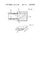
- FIG. 5is a longitudinal cross-sectional side view, on an enlarged scale, of the distal end portion of the tubing subsequent to the cutting step of FIG. 4;
- FIG. 6is a bottom plan view of the distal end portion of the tubing of FIG. 5;
- FIG. 7is a side view of the tubing shown in FIGS. 5 and 6 but with opposed sides clamped together for purpose of explanation;
- FIG. 8is a fragmentary longitudinal cross-sectional view, on an enlarged scale, of the tubing shown in FIG. 7;
- FIG. 9is an illustration of another step in the process of making the catheter of FIG. 1;
- FIG. 10is a side view illustrating the of the distal end portion of the tubing subsequent to the step illustrated in FIG. 9 but with the distal end of the tubing flattened;
- FIG. 11is a fragmentary longitudinal cross-sectional view, on an enlarged scale, of the tubing shown in FIG. 10.
- an intercostal catheter 10including a flexible tube 12 having a proximal end portion 14 and a distal end portion 16.
- Tube 12may be formed of a suitable, resilient and flexible material such as natural or synthetic rubber, a thermosetting plastic, or a thermoplastic.
- the tube 12is an extrusion formed of a thermoplastic material such as a plastisized polyvinyl chloride or the like.
- the tubeis formed of a clear or transparent plastic.
- the proximal end portion 14is shown as being tapered with an end opening 17 and a surrounding proximal end wall 18 generally in a plane at an acute angle, for example, 20° to the center line or longitudinal axis of the tube.
- the end wall 18is generally eliptical as viewed in FIG. 1.
- the tube 12may be formed from extruded tubing having a smoothly curving enlarged portion which may be cut at an angle such as by use of a knife.
- the tapered proximal end 14serves as a tube connector so that a tube such as a suction tube or tube connector (not shown) can be inserted into the tapered proximal end and frictionally connected in fluid tight sealing engagement with catheter 10.
- the tube 12is of substantially constant diameter.
- the proximal end portion 14may be made if desired in accordance with the clamping and cutting steps disclosed in U.S. Pat. No. 3,295,527. In cases where open chest surgery has been performed, the proximal end 14 may be inserted into the original incision and pulled through a secondary incision to place the distal end portion 16 at the desired location within the patient.
- Distal end 16has a distal end opening 20 and end wall 22 which includes a generally eliptical portion 24 generally in a plane at an acute angle to the longitudinal axis of the tube 12, and an arcuate tip portion 26 which is in a plane generally normal to the tube axis.
- a plurality of drainage holes 28are provided in the sidewall of the tube 12 near the distal opening 20.
- the distal arcuate tip 26provides a leading end which is stiffer and resists bending to greater extent than would a pointed tip like that at the proximal end 14.
- the distal end portion 16is adapted to be inserted from the exterior of the patient into a catheter insertion incision, such as a stab wound, and into the desired internal area such as the pleural cavity of the patient for the purpose of providing a negative pressure in the pleural cavity and/or draining fluid from the patient to enhance healing. Insertion of catheter 10 is performed in this manner especially in the case of closed chest drainage where no primary surgical incision has been made for performing an operation.
- the insertion of the catheter 10 by inserting the distal end 16 into the pateint from the exterior of the patientmay, of course, be performed, if desired, even if there is a primary surgical incision.
- the distal end portion 16is formed in accordance with the present invention such that it can be inserted into an incision in a patient with minimal trauma or damage to the patient, as will be discussed hereafter.
- tubingsuch as extruded polyvinyl chloride tubing, indicated at 30, and having a lumen 31, is placed on a platen or chopping board 32 below a vertically reciprocal knife or chopping blade 34.
- the bottom cutting edge of blade 34 and the longitudinal axis of tubing 30are angularly related so that the blade will cut through the tubing, for example, in a plane including a line 36 in FIG. 3.
- Line 36is in a plane at an acute angle, such as an angle of 35° with respect to the longitudinal axis of the tubing 30.
- the knife 34when actuated, comes down and engages and partially flattens the tubing 30 which is supported by the platen by moving one side of the tubing toward the other along the cutting line and cuts through the tubing.
- Tubing 30is thus severed by a chopping action, the knife passing through and engaging the platen.
- the tubing 30then appears as shown in FIG. 4.
- the tubingmay also be cut by the knife 34 or by any other suitable means in a plane including the line indicated at 38 in FIG. 4.
- Line 38is in a plane normal to the longitudinal axis of tubing 30.
- the tubingis cut through to remove a pointed distal tip portion 40 from the tubing. In some cases both angular and normal cuts may be performed by a suitably shaped blade.
- the thus far processed distal end portion of tubing 30is illustrated in FIGS. 5-7.
- the distal end portion of tubing 30, subsequent to the cutting steps indicated in FIGS. 3 and 4has an end wall indicated generally at 42 which has radially inner and outer edges 44 and 46.
- End wall 42includes a somewhat eliptical end wall portion 48 which is generally in a plane at an angle to the longitudinal axis of the tubing 30, and a blunt acurate tip end wall portion 49 in a plane generally normal to the axis of the tubing and which connects with the end wall portion 48.
- the end wall 42terminates at the proximal end thereof in a heel or proximal end wall portion 50 which is inclined radially inwardly and distally from the outer surface of tubing 30.
- the most proximal points on the inner and outer edges 44 and 46are indicated, respectively, at 52 and 54 and are at the inner and outer surfaces, respectively, of tubing 30.
- the end wall 42has a pair of opposed side wall portions 56 and 58 which are connected between the heel 50 and tip 49.
- the distal end of tubing 30is shown in FIG. 7 substantially flattened as a result of the application of forces to the opposed sides of the tubing shown in FIGS. 5 and 6, for example, by arms 60 and 62 of a clamp or forceps and by the forces as indicated by the arrows in FIG. 6.
- the most proximal point 52 on the inner edge 44 of the end wall 42moves generally distally outwardly, so that a protuberance of the end wall 42 is produced as indicated in FIGS. 7 and 8.
- the protuberanceis formed by a portion of the heel 50 of the end wall 42 protruding beyond the outer edge 46 of the end wall 42 while the opposed side wall portions 56 and 58 of the end wall are approximately in the same plane.
- a portion of inner edge 44, the most proximal point 52 of the inner edge 44, and a small surface of the lumen 31protrude distally beyond the outer edge 46.
- This protuberanceoccurs when the opposed sides of the tube adjacent the heel 50 are forced together with tube being creased or folded at the line 64 in FIG. 6.
- Line 64is at the outer surface of the tubing 30 and intersects the most proximal points 52 and 54 of the inner and outer edges dividing the tubing end in symmetrical halves.
- the most proximal point 52 of the inner edgeis shown in longitudinal alignment with point 54 but is radially inwardly thereof. This protuerance occurs if the tubing is similary pinched at the heel 50 between the thumb and a finger.
- an intercostal catheteris made so that it is free of such a protuberance so that the catheter may be pinched or flattened at the heel and passed through an incision without coring or tearing flesh and in general with minimal trauma or deleterious effects to patient. This is accomplished by reshaping, or displacing a portion of the distal end of tubing 30, or removing a part of the proximal portion of the distal end wall, as will be discussed herein.
- a portion of the heel 50is displaced from the distal end of the tubing.
- the tubing material displacedis indicated in FIGS. 5 and 6 between the inner edge 44 and a dashed line 70.
- the most proximal point of the inner edge 44is moved proximally to the dashed line 70 as indicated by a point 72 in FIGS. 5 and 6.
- the slope or incline of the new heel 50is increased and especially between points 54 and 72.
- the material of the heel 50is displaced by melting the plastic material of the heel 50 and distributing it along the tubing.
- the distal end of tubing 30is inserted into a heated melt mold illustrated embodiment, the distal end of tubing 30 is inserted into a heated melt mold such as indicated at 75 in FIG. 9 which not only displaces a portion of heel 50 to prevent the protuberance but also radiuses or rounds the sharp edges resulting from severing the tubing 30.
- the tubingafter being removed from the mold 75, flattened and creased longitudinally at the proximal most points on the new heel 76 (such as along a line 64, FIG. 6), has no protuberance at the distal end of the tubing.
- the mold 75as will be apparent to those skilled in the art, is formed so that as the distal end of tubing 30 moves into the heated mold, the material will flow from the heel area and be spread out onto other surfaces.
- the step indicated in FIG. 9not only simultaneously results in a catheter free of the protuberance or barb indicated in FIG. 7, but efficiently also removes the sharp edges and provides a radius on all sharp edges. Removal of sharp edges, of course, reduces tissue damage.
- the distal end portion of the tubemay be provided with sidewall fluid drainage openings 28, as shown in FIGS. 1 and 10, by conventional or suitable punching apparatus well known to those in the art.
- the distal end 16 of FIG. 10is the same distal end of tubing 30 of FIG. 7 but after the melt-molding step indicated in FIG. 9 and after openings 28 have been made.
- a distal end portion shown in FIG. 10is the finished distal end of the catheter 10 of FIG.
- the intercostal catheter 10 of FIG. 1can thus be utilized for both open and closed chest drainage situations.
- the proximal end 14 of catheter 10may be pulled through a secondary incision from the interior of the patient when there is an original incision by means of a forceps.
- Catheter 10may be used where it is desired to collapse or flatten the distal end 16 by forceps or fingers and pass the distal end into an incision from the exterior of the patient to a desired position within the patient.
- the inclined distal end portion 22 of the catheter 10aids in passing the end through an incision while the blunt tip 26 resists bending that might otherwise interfere with insertion.
- Severing plastic tubing by chopping it as shown and described hereinis quick and easy so that it is an economical method of severing.
- choppingproduces a tube that has a protrusion like that shown in FIGS. 7 and 8 and which is readily avoided in the final product by displacing or removing the heel portion of the distal end opening or end wall as described herein.
- the severing of the tubecan also be performed by a scissors or a scissors-like cutting device.
- Severing the tubing by chopping or by use of a scissorsgenerally produces a heel tha results in an undesirable protuberance but which can be eliminated or reduced by suitable heat melting in accordance with this invention.
Landscapes
- Health & Medical Sciences (AREA)
- Life Sciences & Earth Sciences (AREA)
- Biophysics (AREA)
- Pulmonology (AREA)
- Engineering & Computer Science (AREA)
- Anesthesiology (AREA)
- Biomedical Technology (AREA)
- Heart & Thoracic Surgery (AREA)
- Hematology (AREA)
- Animal Behavior & Ethology (AREA)
- General Health & Medical Sciences (AREA)
- Public Health (AREA)
- Veterinary Medicine (AREA)
- Media Introduction/Drainage Providing Device (AREA)
Abstract
Description
This invention relates to catheters and more particularly to an intercostal catheter and to the method of making the same.
As is well known, intercostal catheters have a distal end which may be inserted into the plural cavity of a patient for maintaining a negative pressure in the plural cavity where required and/or to remove wound drainage fluid from a wound or surgical incision to aid the healing process.
In U.S. Pat. No. 3,295,527, an intercostal catheter is shown having a funnel-like proximal end formed at an angle to the longitudinal axis of the tube and which has a point at the proximal tip. The distal end is a blunt end normal to the axis of the tube and is provided with a plurality of drainage openings in the sidewall adjacent the distal end. The proximal end may serve as a tube connector for connecting tubing to a drainage collection system that may include a source of suction. Where a surgical incision has been made for performing surgery, the proximal end is generally inserted through the surgical incision and then pulled, such as with forceps, through a secondary incision to the exterior of the patient until the distal end moves into the desired location within the patient. As the forceps pull the proximal end through the second incision, the open proximal end of the catheter tends to close reducing damage to the patient. The proximal end of the cath ter is formed in accordance with that patent by placing the tubing from which it is formed in a clamp, pressing the tube flat, and then cutting at the desired angle.
In cases where the chest of the patient is closed, for example, where there has been no incision into the plural cavity or open chest surgery but where there has been a puncture of the lung or other internal damage, such as due to an accident, the distal end of an intercostal catheter can be pinched, such as by forceps or by the fingers, and forced or tunneled from the exterior of the patient through an entrance incision, such as a stab wound or incision which passes between the ribs of the patient. Such a catheter may be connected to a suction source to maintain the plural cavity at a negative pressure to allow the lung to expand for breathing and so that fluid can readily drain from the wound.
Where the distal end of the catheter has a blunt end or is formed normal to the longitudinal axis of the tube, and is squeezed by the fingers or by forceps and moved into the incision from the exterior of the patient, the opposed sides of the substantially flattened end tend to increase in size and present a wide tube end extending normal to the tube axis. As a result, the catheter tends to tear or otherwise damage flesh during its movement through the incision into its desired location within the patient. In some other catheter constructions, undesirable protuberances occur when the distal end of the intercostal catheter is flattened during insertion.
Trocar catheters have also been used for closed-chest drainage. However, insertion of the catheter and pointed trocar into the patient has the potential danger of damaging the patient, such as piercing the lung, as a result of the insertion technique.
It is therefore an object of the present invention to provide an improved catheter having a distal end for insertion into an incision wherein the distal end is shaped to reduce or eliminate undesirable protuberances when flattened for insertion.
Another object of the present invention is to provide an intercostal catheter having a distal end with a shape which when laterally compressed can be readily inserted into an incision of a patient from the exterior of the patient with minimal traumatic effects.
Still another object of the present invention is to provide an improved method of making a catheter of the above type.
Still another object of the present invention is to provide an intercostal catheter and method of making the same which substantially avoids one or more of the above mentioned problems or disadvantages associated with prior art devices.
In accordance with one aspect of the invention, a method of making a catheter is provided which includes the steps of severing flexible tubing including cutting the tubing at an angle to the longitudinal axis of the tubing to form a distal end wall that has a distal tip, and a proximal end wall portion inclined radially inwardly. A part of the proximal wall portion is displaced to substantially prevent the proximal wall portion from extending distally beyond the outer edge of the end wall when the distal end portion is flattened for insertion into a patient. In accordance with another aspect of the invention, an intercostal catheter is provided which is made in accordance with the above-mentioned method.
These, as well as other objects and advantages of the present invention, will become apparent from the following detailed description and accompanying drawings.
FIG. 1 is a top view of an intercostal catheter made in accordance with the present invention;
FIGS. 2-4 are illustrations of cutting steps employed in the manufacture of the catheter of FIG. 1;
FIG. 5 is a longitudinal cross-sectional side view, on an enlarged scale, of the distal end portion of the tubing subsequent to the cutting step of FIG. 4;
FIG. 6 is a bottom plan view of the distal end portion of the tubing of FIG. 5;
FIG. 7 is a side view of the tubing shown in FIGS. 5 and 6 but with opposed sides clamped together for purpose of explanation;
FIG. 8 is a fragmentary longitudinal cross-sectional view, on an enlarged scale, of the tubing shown in FIG. 7;
FIG. 9 is an illustration of another step in the process of making the catheter of FIG. 1;
FIG. 10 is a side view illustrating the of the distal end portion of the tubing subsequent to the step illustrated in FIG. 9 but with the distal end of the tubing flattened; and
FIG. 11 is a fragmentary longitudinal cross-sectional view, on an enlarged scale, of the tubing shown in FIG. 10.
Referring now to the drawings and particularly of FIG. 1, anintercostal catheter 10 is shown including aflexible tube 12 having aproximal end portion 14 and adistal end portion 16.Tube 12 may be formed of a suitable, resilient and flexible material such as natural or synthetic rubber, a thermosetting plastic, or a thermoplastic. Preferably, thetube 12 is an extrusion formed of a thermoplastic material such as a plastisized polyvinyl chloride or the like. Preferably the tube is formed of a clear or transparent plastic.
Theproximal end portion 14 is shown as being tapered with an end opening 17 and a surroundingproximal end wall 18 generally in a plane at an acute angle, for example, 20° to the center line or longitudinal axis of the tube. Theend wall 18 is generally eliptical as viewed in FIG. 1. Thetube 12 may be formed from extruded tubing having a smoothly curving enlarged portion which may be cut at an angle such as by use of a knife. The taperedproximal end 14 serves as a tube connector so that a tube such as a suction tube or tube connector (not shown) can be inserted into the tapered proximal end and frictionally connected in fluid tight sealing engagement withcatheter 10. Except for the enlarged proximal end portion, thetube 12 is of substantially constant diameter. Theproximal end portion 14 may be made if desired in accordance with the clamping and cutting steps disclosed in U.S. Pat. No. 3,295,527. In cases where open chest surgery has been performed, theproximal end 14 may be inserted into the original incision and pulled through a secondary incision to place thedistal end portion 16 at the desired location within the patient.
The present invention is especially concerned with thedistal end portion 16 ofcatheter 10.Distal end 16 has a distal end opening 20 andend wall 22 which includes a generallyeliptical portion 24 generally in a plane at an acute angle to the longitudinal axis of thetube 12, and anarcuate tip portion 26 which is in a plane generally normal to the tube axis. A plurality ofdrainage holes 28 are provided in the sidewall of thetube 12 near thedistal opening 20. The distalarcuate tip 26 provides a leading end which is stiffer and resists bending to greater extent than would a pointed tip like that at theproximal end 14.
Thedistal end portion 16 is adapted to be inserted from the exterior of the patient into a catheter insertion incision, such as a stab wound, and into the desired internal area such as the pleural cavity of the patient for the purpose of providing a negative pressure in the pleural cavity and/or draining fluid from the patient to enhance healing. Insertion ofcatheter 10 is performed in this manner especially in the case of closed chest drainage where no primary surgical incision has been made for performing an operation. The insertion of thecatheter 10 by inserting thedistal end 16 into the pateint from the exterior of the patient may, of course, be performed, if desired, even if there is a primary surgical incision. Thedistal end portion 16 is formed in accordance with the present invention such that it can be inserted into an incision in a patient with minimal trauma or damage to the patient, as will be discussed hereafter.
Referring now to FIG. 2, in the manufacture ofcatheter 10, tubing such as extruded polyvinyl chloride tubing, indicated at 30, and having alumen 31, is placed on a platen or choppingboard 32 below a vertically reciprocal knife or choppingblade 34. The bottom cutting edge ofblade 34 and the longitudinal axis oftubing 30 are angularly related so that the blade will cut through the tubing, for example, in a plane including aline 36 in FIG. 3.Line 36 is in a plane at an acute angle, such as an angle of 35° with respect to the longitudinal axis of thetubing 30. Theknife 34, when actuated, comes down and engages and partially flattens thetubing 30 which is supported by the platen by moving one side of the tubing toward the other along the cutting line and cuts through the tubing. Tubing 30 is thus severed by a chopping action, the knife passing through and engaging the platen. Thetubing 30 then appears as shown in FIG. 4. The tubing may also be cut by theknife 34 or by any other suitable means in a plane including the line indicated at 38 in FIG. 4.Line 38 is in a plane normal to the longitudinal axis oftubing 30. As indicated in FIG. 4, the tubing is cut through to remove a pointeddistal tip portion 40 from the tubing. In some cases both angular and normal cuts may be performed by a suitably shaped blade. The thus far processed distal end portion oftubing 30 is illustrated in FIGS. 5-7.
As seen FIGS. 5 and 6, the distal end portion oftubing 30, subsequent to the cutting steps indicated in FIGS. 3 and 4 has an end wall indicated generally at 42 which has radially inner andouter edges End wall 42 includes a somewhat elipticalend wall portion 48 which is generally in a plane at an angle to the longitudinal axis of thetubing 30, and a blunt acurate tipend wall portion 49 in a plane generally normal to the axis of the tubing and which connects with theend wall portion 48. Theend wall 42 terminates at the proximal end thereof in a heel or proximalend wall portion 50 which is inclined radially inwardly and distally from the outer surface oftubing 30. The most proximal points on the inner andouter edges tubing 30. Theend wall 42 has a pair of opposedside wall portions heel 50 andtip 49.
For purposes of illustration only, the distal end oftubing 30 is shown in FIG. 7 substantially flattened as a result of the application of forces to the opposed sides of the tubing shown in FIGS. 5 and 6, for example, byarms proximal point 52 on theinner edge 44 of theend wall 42 moves generally distally outwardly, so that a protuberance of theend wall 42 is produced as indicated in FIGS. 7 and 8. The protuberance is formed by a portion of theheel 50 of theend wall 42 protruding beyond theouter edge 46 of theend wall 42 while the opposedside wall portions inner edge 44, the mostproximal point 52 of theinner edge 44, and a small surface of thelumen 31 protrude distally beyond theouter edge 46. This protuberance occurs when the opposed sides of the tube adjacent theheel 50 are forced together with tube being creased or folded at theline 64 in FIG. 6.Line 64 is at the outer surface of thetubing 30 and intersects the mostproximal points proximal point 52 of the inner edge is shown in longitudinal alignment withpoint 54 but is radially inwardly thereof. This protuerance occurs if the tubing is similary pinched at theheel 50 between the thumb and a finger.
It is seen from FIG. 7 that if thetubing 30 thus far processed was flattened at theheel 50 by creasing atline 64, and then inserted into an incision from the exterior of the patient, that the protuberance of theheel 50 would act as a barb and could produce deleterious effects on th flesh of the patient. However, in accordance with the present invention, an intercostal catheter is made so that it is free of such a protuberance so that the catheter may be pinched or flattened at the heel and passed through an incision without coring or tearing flesh and in general with minimal trauma or deleterious effects to patient. This is accomplished by reshaping, or displacing a portion of the distal end oftubing 30, or removing a part of the proximal portion of the distal end wall, as will be discussed herein.
In providing an intercostal catheter without a heel protuberance or deleterious barb, such as indicated in FIGS. 7 and 8, a portion of theheel 50 is displaced from the distal end of the tubing. For purposes of illustration and understanding, the tubing material displaced is indicated in FIGS. 5 and 6 between theinner edge 44 and a dashedline 70. In effect, the most proximal point of theinner edge 44 is moved proximally to the dashedline 70 as indicated by apoint 72 in FIGS. 5 and 6. In this way, the slope or incline of thenew heel 50 is increased and especially betweenpoints tubing 30 is pinched or flattened by opposing forces such as indicated by the arrows in FIG. 6, no protuberance is formed. This is because the new proximal extremity of the end wall and the new inneredge including point 72 will not extend distally beyond theouter edge 46 of the end wall upon being compressed or flattened and creased online 64.
Preferably, the material of theheel 50 is displaced by melting the plastic material of theheel 50 and distributing it along the tubing. In the preferred illustrated embodiment, the distal end oftubing 30 is inserted into a heated melt mold illustrated embodiment, the distal end oftubing 30 is inserted into a heated melt mold such as indicated at 75 in FIG. 9 which not only displaces a portion ofheel 50 to prevent the protuberance but also radiuses or rounds the sharp edges resulting from severing thetubing 30.
As seen in FIG. 9, the tubing, after being removed from themold 75, flattened and creased longitudinally at the proximal most points on the new heel 76 (such as along aline 64, FIG. 6), has no protuberance at the distal end of the tubing. Themold 75, as will be apparent to those skilled in the art, is formed so that as the distal end oftubing 30 moves into the heated mold, the material will flow from the heel area and be spread out onto other surfaces.
The step indicated in FIG. 9 not only simultaneously results in a catheter free of the protuberance or barb indicated in FIG. 7, but efficiently also removes the sharp edges and provides a radius on all sharp edges. Removal of sharp edges, of course, reduces tissue damage. The distal end portion of the tube may be provided with sidewallfluid drainage openings 28, as shown in FIGS. 1 and 10, by conventional or suitable punching apparatus well known to those in the art. Thedistal end 16 of FIG. 10 is the same distal end oftubing 30 of FIG. 7 but after the melt-molding step indicated in FIG. 9 and afteropenings 28 have been made. Thus, a distal end portion shown in FIG. 10 is the finished distal end of thecatheter 10 of FIG. 1 but in the pinched or flattened condition ready for insertion into an incision from the exterior of the patient. It is seen in FIG. 10 that no protrusion or barb extends distally from thedistal end wall 22 of the catheter when the catheter is pinched or folded at the heel. As seen also from FIG. 11, the new heel, indicated at 76, moves distally but not distally past the distal end of the tube when the distal end is flattened or pinched at the heel.
Theintercostal catheter 10 of FIG. 1 can thus be utilized for both open and closed chest drainage situations. For Example, as pointed out previously theproximal end 14 ofcatheter 10 may be pulled through a secondary incision from the interior of the patient when there is an original incision by means of a forceps.Catheter 10, on the other hand, may be used where it is desired to collapse or flatten thedistal end 16 by forceps or fingers and pass the distal end into an incision from the exterior of the patient to a desired position within the patient. The inclineddistal end portion 22 of thecatheter 10 aids in passing the end through an incision while theblunt tip 26 resists bending that might otherwise interfere with insertion.
Severing plastic tubing by chopping it as shown and described herein is quick and easy so that it is an economical method of severing. Generally, such chopping produces a tube that has a protrusion like that shown in FIGS. 7 and 8 and which is readily avoided in the final product by displacing or removing the heel portion of the distal end opening or end wall as described herein. The severing of the tube can also be performed by a scissors or a scissors-like cutting device. Severing the tubing by chopping or by use of a scissors generally produces a heel tha results in an undesirable protuberance but which can be eliminated or reduced by suitable heat melting in accordance with this invention.
As various changes could be made in the above described construction and method without departing from the true spirit and scope of the invention, it is intended that all matter contained in the above description and shown in the accompanying drawings be interpreted as illustrative.
Claims (17)
1. In a method of making a catheter, the steps of severing resilient flexible tubing including cutting the tubing generally in a plane at an angle to the longitudinal axis of the tubing to effect a distal end wall having a distal tip, a proximal wall portion, and a pair of opposed sidewalls connecting the distal tip with the proximal wall portion, and such that the proximal wall portion protrudes distally beyond the dista end of the tubing when the opposed end walls are pinched together adjacent the proximal end wall portion, and the tubing being in a substantially unflattened state at the cutting site when said step of severing is initiated, displacing a sufficient part of the proximal wall portion to substantially prevent the proximal wall portion from protruding distally beyond the distal end of the tubing when the sidewalls are pinched together adjacent the proximal end wall portion.
2. The method of claim 1 wherein said step of displacing a sufficient part of the proximal wall portion includes the step of melt-forming a part of the proximal wall portion.
3. The method of claim 2 wherein said tubing has a constant diameter portion, and said step of severing the flexible tubing is made by chopping the tubing in the constant diameter portion with a cutting element while the tubing is on a platen.
4. The method of claim 2 wherein said step of melt-forming includes providing a melt-forming mold, and inserting the distal end of the tubing into the mold, the mold being shaped to displace the sufficient part of the proximal wall portion.
5. The method of claim 4 wherein said mold is shaped to further effect rounding of all edges of the distal end of the tubing by melting the edges during insertion of the distal end of the tubing in the mold.
6. The method of claim 5 wherein said cutting of the tubing is made by chopping the tubing with a cutting element while on a platen.
7. In a method of making an intercostal catheter having a distal end wall adapted to be inserted into an incision in a patient from the exterior of the patient, the steps of severing resilient flexible tubing including cutting the tubing in a plane at an angle to the longitudinal axis of the tubing to effect a distal end wall having radially inner and outer edges and defining a distal end opening, the distal end wall having a distal tip, a proximal end wall portion inclined radially inwardly, and opposed side wall portions connected between the distal tip and the tubing being in a substantially unflattened state at the cutting site when said step of severing is initiated, proximal end wall portion, the proximal end wall portion being invertible in response to the substantial flattening of the distal end of the tubing by movement of the opposed sidewall portions together with the tubing creased longitudinally at the most proximal point on the outer edge to thereby effect a protruding part of the proximal end wall portion that etends distally outwardly beyond the outer edge of the end wall, and displacing a sufficient portion of the proximal end wall portion to substantially prevent the proximal end wall portion from extending beyond the outer edge when the distal end of the tubing is similarly flattened.
8. The method of claim 7 wherein said displacing step includes melting a portion of the proximal end wall portion.
9. The method of claim 8 wherein said melting step includes inserting the distal end of the tubing in a heated mold.
10. The method of claim 9 wherein said severing step comprises chopping the tubing on a platen.
11. The method of claim 9 wherein all sharp edges are rounded by melting during said insertion of the distal end in the mold.
12. The method of claim 7 wherein the tubing has an enlarged tapered portion, and includes the step of cutting through the tapered portion to provide an open tube connector at the proximal end of the tubing.
13. An intercostal catheter made according to claim 7.
14. The intercostal catheter of claim 13 further including a proximal open end tapered to serve as a tube connector.
15. The method of claim 1 wherein said cutting step includes placing the tubing in its normal unflattened state between a cutting blade and platen means, and moving the blade to engage a portion of the tubing while in the unflattened state and thereafter passing the blade through the tubing.
16. The method of claim 15 wherein the tubing is formed of a thermoplastic material.
17. The method of claim 8 wherein the tubing is formed of a thermoplastic maerial and is normally circular in cross-section.
Priority Applications (1)
| Application Number | Priority Date | Filing Date | Title |
|---|---|---|---|
| US06/655,853US4617019A (en) | 1984-09-28 | 1984-09-28 | Catheter |
Applications Claiming Priority (1)
| Application Number | Priority Date | Filing Date | Title |
|---|---|---|---|
| US06/655,853US4617019A (en) | 1984-09-28 | 1984-09-28 | Catheter |
Publications (1)
| Publication Number | Publication Date |
|---|---|
| US4617019Atrue US4617019A (en) | 1986-10-14 |
Family
ID=24630654
Family Applications (1)
| Application Number | Title | Priority Date | Filing Date |
|---|---|---|---|
| US06/655,853Expired - LifetimeUS4617019A (en) | 1984-09-28 | 1984-09-28 | Catheter |
Country Status (1)
| Country | Link |
|---|---|
| US (1) | US4617019A (en) |
Cited By (69)
| Publication number | Priority date | Publication date | Assignee | Title |
|---|---|---|---|---|
| EP0253606A3 (en)* | 1986-07-14 | 1990-05-02 | David S. Sheridan | Marlin thoracic catheter |
| JPH02501319A (en)* | 1987-05-14 | 1990-05-10 | ベロイト・コーポレイション | head box |
| US5037403A (en)* | 1989-11-08 | 1991-08-06 | Cordis Corporation | Pigtail catheter with angled apertures |
| US5057083A (en)* | 1989-07-25 | 1991-10-15 | C. R. Bard, Inc. | Vascular dilator with truncated tip |
| US5085648A (en)* | 1990-09-13 | 1992-02-04 | Becton Dickinson And Company | Dual diameter needle with a smooth transition |
| US5207658A (en)* | 1991-11-14 | 1993-05-04 | Rosen Howard J | Prick resistant medical needle for intravenous injections |
| US5209742A (en)* | 1989-09-13 | 1993-05-11 | Cordis Corporation | Curved catheter with eccentric lumen |
| US5342325A (en)* | 1992-12-07 | 1994-08-30 | Dlp, Incorporated | Introducer needle and catheter assembly |
| US5354288A (en)* | 1993-02-24 | 1994-10-11 | Minnesota Mining And Manufacturing Company | Low velocity aortic cannula |
| US5554138A (en)* | 1994-12-12 | 1996-09-10 | Medovations | Thoracic catheter with elongated pulling lead |
| EP0513836B1 (en)* | 1991-05-17 | 1997-03-05 | Act Medical, Inc. | Device having a radiopaque marker for endoscopic accessories and method of making same |
| US5616137A (en)* | 1995-02-22 | 1997-04-01 | Minnesota Mining And Manufacturing Company | Low velocity aortic cannula |
| US5643226A (en)* | 1993-02-24 | 1997-07-01 | Minnesota Mining And Manufacturing | Low velocity aortic cannula |
| US5833662A (en)* | 1995-01-19 | 1998-11-10 | Stevens; Robert C. | Hemostasis cannula system |
| US5876383A (en)* | 1997-09-30 | 1999-03-02 | Grooters; Robert K. | Cannula |
| US6186987B1 (en) | 1997-09-30 | 2001-02-13 | Ronald K. Grooters | Aortic cannula with spoon-shaped lip |
| US6206852B1 (en) | 1999-12-15 | 2001-03-27 | Advanced Cardiovascular Systems, Inc. | Balloon catheter having a small profile catheter |
| US6254578B1 (en) | 1997-09-30 | 2001-07-03 | Ronald K. Grooters | Aortic cannula with tapered tip |
| KR100349240B1 (en)* | 2000-04-08 | 2002-08-19 | 민병무 | A check valve typed thoracic cavity inserting tube |
| US6712797B1 (en) | 2000-09-19 | 2004-03-30 | Board Of Supervisors Of Louisiana State University And Agricultural And Mechanical College | Blood return catheter |
| US6951555B1 (en) | 1998-03-16 | 2005-10-04 | Chase Medical, L.P. | Catheter having integral expandable/collapsible lumen |
| US20060135916A1 (en)* | 2004-12-16 | 2006-06-22 | Smiths Medical Asd, Inc. | Catheter with direction orientation |
| US20070123935A1 (en)* | 2005-11-30 | 2007-05-31 | Myers Gene E | Method and apparatus for contemporaneous formation of a body structure opening and homologous pedicle |
| WO2008104603A1 (en)* | 2007-02-28 | 2008-09-04 | Coloplast A/S | Method for rounding edges of openings in a tubular body and a product thereof |
| US20080236358A1 (en)* | 2007-03-27 | 2008-10-02 | Vitullo Jeffrey M | Catheter trimmer |
| WO2008155145A1 (en)* | 2007-06-20 | 2008-12-24 | Unomedical A/S | A catheter and a method and an apparatus for making such catheter |
| US20090187143A1 (en)* | 2008-01-18 | 2009-07-23 | Ev3 Inc. | Angled tip catheter |
| US20100004597A1 (en)* | 2006-08-02 | 2010-01-07 | Unomedical A/S | Insertion Device |
| US20100030155A1 (en)* | 2006-08-02 | 2010-02-04 | Steffen Gyrn | Cannula and Delivery Device |
| US20100137829A1 (en)* | 2007-02-02 | 2010-06-03 | Nielsen Henrik Boeje | Injection Gateway |
| US20100140125A1 (en)* | 2007-02-02 | 2010-06-10 | Orla Mathiasen | Injection Site for Injecting Medication |
| WO2011047753A1 (en)* | 2009-10-19 | 2011-04-28 | Ferrosan Medical Devices A/S | Malleable tip for agent applicator to a target site |
| US7985199B2 (en) | 2005-03-17 | 2011-07-26 | Unomedical A/S | Gateway system |
| US8012126B2 (en) | 2006-10-31 | 2011-09-06 | Unomedical A/S | Infusion set |
| US8062250B2 (en) | 2004-08-10 | 2011-11-22 | Unomedical A/S | Cannula device |
| US8221355B2 (en) | 2004-03-26 | 2012-07-17 | Unomedical A/S | Injection device for infusion set |
| US8246588B2 (en) | 2007-07-18 | 2012-08-21 | Unomedical A/S | Insertion device with pivoting action |
| US8303549B2 (en) | 2005-12-23 | 2012-11-06 | Unomedical A/S | Injection device |
| US8430850B2 (en) | 2007-07-03 | 2013-04-30 | Unomedical A/S | Inserter having bistable equilibrium states |
| US8439838B2 (en) | 2006-06-07 | 2013-05-14 | Unomedical A/S | Inserter for transcutaneous sensor |
| US8486003B2 (en) | 2007-07-10 | 2013-07-16 | Unomedical A/S | Inserter having two springs |
| US8562567B2 (en) | 2009-07-30 | 2013-10-22 | Unomedical A/S | Inserter device with horizontal moving part |
| US8790311B2 (en) | 2006-06-09 | 2014-07-29 | Unomedical A/S | Mounting pad |
| US9211379B2 (en) | 2006-02-28 | 2015-12-15 | Unomedical A/S | Inserter for infusion part and infusion part provided with needle protector |
| US9254373B2 (en) | 2008-12-22 | 2016-02-09 | Unomedical A/S | Medical device comprising adhesive pad |
| US9415159B2 (en) | 2010-03-30 | 2016-08-16 | Unomedical A/S | Medical device |
| US9440051B2 (en) | 2011-10-27 | 2016-09-13 | Unomedical A/S | Inserter for a multiplicity of subcutaneous parts |
| US9533092B2 (en) | 2009-08-07 | 2017-01-03 | Unomedical A/S | Base part for a medication delivery device |
| US9566384B2 (en) | 2008-02-20 | 2017-02-14 | Unomedical A/S | Insertion device with horizontally moving part |
| US9724127B2 (en) | 2010-09-27 | 2017-08-08 | Unomedical A/S | Insertion system and insertion kit |
| US10369277B2 (en) | 2005-09-12 | 2019-08-06 | Unomedical A/S | Invisible needle |
| US10532152B2 (en)* | 2010-03-17 | 2020-01-14 | Solvay Specialty Polymers Usa, L.L.C. | Needles made of a particular plastic material |
| CN111529019A (en)* | 2020-04-10 | 2020-08-14 | 周倩柔 | Obstetric artificial membrane rupture device |
| US10898643B2 (en) | 2008-02-13 | 2021-01-26 | Unomedical A/S | Sealing between a cannula part and a fluid path |
| US11020526B2 (en) | 2010-10-04 | 2021-06-01 | Unomedical A/S | Sprinkler cannula |
| US11110261B2 (en) | 2011-10-19 | 2021-09-07 | Unomedical A/S | Infusion tube system and method for manufacture |
| US11197689B2 (en) | 2011-10-05 | 2021-12-14 | Unomedical A/S | Inserter for simultaneous insertion of multiple transcutaneous parts |
| US11395665B2 (en) | 2018-05-01 | 2022-07-26 | Incept, Llc | Devices and methods for removing obstructive material, from an intravascular site |
| US11439799B2 (en) | 2019-12-18 | 2022-09-13 | Imperative Care, Inc. | Split dilator aspiration system |
| US11471582B2 (en) | 2018-07-06 | 2022-10-18 | Incept, Llc | Vacuum transfer tool for extendable catheter |
| US11504020B2 (en) | 2019-10-15 | 2022-11-22 | Imperative Care, Inc. | Systems and methods for multivariate stroke detection |
| US11517335B2 (en) | 2018-07-06 | 2022-12-06 | Incept, Llc | Sealed neurovascular extendable catheter |
| US11553935B2 (en) | 2019-12-18 | 2023-01-17 | Imperative Care, Inc. | Sterile field clot capture module for use in thrombectomy system |
| US11565082B2 (en) | 2020-03-10 | 2023-01-31 | Imperative Care, Inc. | Enhanced flexibility neurovascular catheter |
| US11819228B2 (en) | 2019-12-18 | 2023-11-21 | Imperative Care, Inc. | Methods and systems for treating a pulmonary embolism |
| US11903588B2 (en) | 2017-01-06 | 2024-02-20 | Incept, Llc | Thromboresistant coatings for aneurysm treatment devices |
| US12232838B2 (en) | 2021-08-12 | 2025-02-25 | Imperative Care, Inc. | Method of robotically performing a neurovascular procedure |
| USD1077996S1 (en) | 2021-10-18 | 2025-06-03 | Imperative Care, Inc. | Inline fluid filter |
| US12343479B2 (en) | 2016-02-24 | 2025-07-01 | Incept, Llc | Neurovascular catheter |
Citations (8)
| Publication number | Priority date | Publication date | Assignee | Title |
|---|---|---|---|---|
| US1879249A (en)* | 1931-04-07 | 1932-09-27 | Honsaker Charles Coy | Colonic tube |
| US2972779A (en)* | 1954-06-07 | 1961-02-28 | Baxter Don Inc | Plastic tubing process |
| US3064651A (en)* | 1959-05-26 | 1962-11-20 | Henderson Edward | Hypodermic needle |
| US3190290A (en)* | 1962-02-08 | 1965-06-22 | Brunswick Corp | Intercostal catheters |
| US3295527A (en)* | 1964-04-10 | 1967-01-03 | Sheridan Corp | Intercostal catheter |
| US3625793A (en)* | 1969-09-23 | 1971-12-07 | David S Sheridan | Balloon-type catheters and method of manufacture |
| US3656486A (en)* | 1970-04-08 | 1972-04-18 | Jack R Robertson | Instrument for inserting a suprapubic catheter |
| JPS5769861A (en)* | 1980-10-20 | 1982-04-28 | Terumo Corp | Method of working inserting nose section of catheter |
- 1984
- 1984-09-28USUS06/655,853patent/US4617019A/ennot_activeExpired - Lifetime
Patent Citations (8)
| Publication number | Priority date | Publication date | Assignee | Title |
|---|---|---|---|---|
| US1879249A (en)* | 1931-04-07 | 1932-09-27 | Honsaker Charles Coy | Colonic tube |
| US2972779A (en)* | 1954-06-07 | 1961-02-28 | Baxter Don Inc | Plastic tubing process |
| US3064651A (en)* | 1959-05-26 | 1962-11-20 | Henderson Edward | Hypodermic needle |
| US3190290A (en)* | 1962-02-08 | 1965-06-22 | Brunswick Corp | Intercostal catheters |
| US3295527A (en)* | 1964-04-10 | 1967-01-03 | Sheridan Corp | Intercostal catheter |
| US3625793A (en)* | 1969-09-23 | 1971-12-07 | David S Sheridan | Balloon-type catheters and method of manufacture |
| US3656486A (en)* | 1970-04-08 | 1972-04-18 | Jack R Robertson | Instrument for inserting a suprapubic catheter |
| JPS5769861A (en)* | 1980-10-20 | 1982-04-28 | Terumo Corp | Method of working inserting nose section of catheter |
Cited By (94)
| Publication number | Priority date | Publication date | Assignee | Title |
|---|---|---|---|---|
| EP0253606A3 (en)* | 1986-07-14 | 1990-05-02 | David S. Sheridan | Marlin thoracic catheter |
| JPH02501319A (en)* | 1987-05-14 | 1990-05-10 | ベロイト・コーポレイション | head box |
| US5057083A (en)* | 1989-07-25 | 1991-10-15 | C. R. Bard, Inc. | Vascular dilator with truncated tip |
| US5209742A (en)* | 1989-09-13 | 1993-05-11 | Cordis Corporation | Curved catheter with eccentric lumen |
| US5037403A (en)* | 1989-11-08 | 1991-08-06 | Cordis Corporation | Pigtail catheter with angled apertures |
| US5085648A (en)* | 1990-09-13 | 1992-02-04 | Becton Dickinson And Company | Dual diameter needle with a smooth transition |
| EP0513836B1 (en)* | 1991-05-17 | 1997-03-05 | Act Medical, Inc. | Device having a radiopaque marker for endoscopic accessories and method of making same |
| US5207658A (en)* | 1991-11-14 | 1993-05-04 | Rosen Howard J | Prick resistant medical needle for intravenous injections |
| US5342325A (en)* | 1992-12-07 | 1994-08-30 | Dlp, Incorporated | Introducer needle and catheter assembly |
| US5354288A (en)* | 1993-02-24 | 1994-10-11 | Minnesota Mining And Manufacturing Company | Low velocity aortic cannula |
| US5643226A (en)* | 1993-02-24 | 1997-07-01 | Minnesota Mining And Manufacturing | Low velocity aortic cannula |
| US5685865A (en)* | 1993-02-24 | 1997-11-11 | Minnesota Mining And Manufacturing Company | Low velocity aortic cannula |
| US5554138A (en)* | 1994-12-12 | 1996-09-10 | Medovations | Thoracic catheter with elongated pulling lead |
| US5833662A (en)* | 1995-01-19 | 1998-11-10 | Stevens; Robert C. | Hemostasis cannula system |
| US5616137A (en)* | 1995-02-22 | 1997-04-01 | Minnesota Mining And Manufacturing Company | Low velocity aortic cannula |
| US5876383A (en)* | 1997-09-30 | 1999-03-02 | Grooters; Robert K. | Cannula |
| US6186987B1 (en) | 1997-09-30 | 2001-02-13 | Ronald K. Grooters | Aortic cannula with spoon-shaped lip |
| US6758834B2 (en) | 1997-09-30 | 2004-07-06 | Ronald K. Grooters | Aortic cannula with spoon-shaped lip |
| US6254578B1 (en) | 1997-09-30 | 2001-07-03 | Ronald K. Grooters | Aortic cannula with tapered tip |
| US6951555B1 (en) | 1998-03-16 | 2005-10-04 | Chase Medical, L.P. | Catheter having integral expandable/collapsible lumen |
| US6206852B1 (en) | 1999-12-15 | 2001-03-27 | Advanced Cardiovascular Systems, Inc. | Balloon catheter having a small profile catheter |
| KR100349240B1 (en)* | 2000-04-08 | 2002-08-19 | 민병무 | A check valve typed thoracic cavity inserting tube |
| US6712797B1 (en) | 2000-09-19 | 2004-03-30 | Board Of Supervisors Of Louisiana State University And Agricultural And Mechanical College | Blood return catheter |
| US8287516B2 (en) | 2004-03-26 | 2012-10-16 | Unomedical A/S | Infusion set |
| US8221355B2 (en) | 2004-03-26 | 2012-07-17 | Unomedical A/S | Injection device for infusion set |
| US8062250B2 (en) | 2004-08-10 | 2011-11-22 | Unomedical A/S | Cannula device |
| US8597260B2 (en) | 2004-12-16 | 2013-12-03 | Smiths Medical Asd, Inc. | Catheter with direction orientation |
| US8348908B2 (en) | 2004-12-16 | 2013-01-08 | Smiths Medical Asd, Inc. | Catheter with direction orientation |
| US20060135916A1 (en)* | 2004-12-16 | 2006-06-22 | Smiths Medical Asd, Inc. | Catheter with direction orientation |
| US20060135915A1 (en)* | 2004-12-16 | 2006-06-22 | Smiths Medical Asd, Inc. | Catheter with direction orientation |
| US7985199B2 (en) | 2005-03-17 | 2011-07-26 | Unomedical A/S | Gateway system |
| US10369277B2 (en) | 2005-09-12 | 2019-08-06 | Unomedical A/S | Invisible needle |
| US20070123935A1 (en)* | 2005-11-30 | 2007-05-31 | Myers Gene E | Method and apparatus for contemporaneous formation of a body structure opening and homologous pedicle |
| US9278173B2 (en) | 2005-12-23 | 2016-03-08 | Unomedical A/S | Device for administration |
| US8303549B2 (en) | 2005-12-23 | 2012-11-06 | Unomedical A/S | Injection device |
| US9211379B2 (en) | 2006-02-28 | 2015-12-15 | Unomedical A/S | Inserter for infusion part and infusion part provided with needle protector |
| US8439838B2 (en) | 2006-06-07 | 2013-05-14 | Unomedical A/S | Inserter for transcutaneous sensor |
| US8790311B2 (en) | 2006-06-09 | 2014-07-29 | Unomedical A/S | Mounting pad |
| US20100030155A1 (en)* | 2006-08-02 | 2010-02-04 | Steffen Gyrn | Cannula and Delivery Device |
| US20100004597A1 (en)* | 2006-08-02 | 2010-01-07 | Unomedical A/S | Insertion Device |
| US8945057B2 (en) | 2006-08-02 | 2015-02-03 | Unomedical A/S | Cannula and delivery device |
| US8012126B2 (en) | 2006-10-31 | 2011-09-06 | Unomedical A/S | Infusion set |
| US20100137829A1 (en)* | 2007-02-02 | 2010-06-03 | Nielsen Henrik Boeje | Injection Gateway |
| US20100140125A1 (en)* | 2007-02-02 | 2010-06-10 | Orla Mathiasen | Injection Site for Injecting Medication |
| US8475699B2 (en) | 2007-02-28 | 2013-07-02 | Coloplast A/S | Method for rounding edges of openings in a tubular body and a product thereof |
| US20100324535A1 (en)* | 2007-02-28 | 2010-12-23 | Coloplast A/S | Method for rounding edges of openings in a tubular body and a product thereof. |
| WO2008104603A1 (en)* | 2007-02-28 | 2008-09-04 | Coloplast A/S | Method for rounding edges of openings in a tubular body and a product thereof |
| EP2944345A1 (en)* | 2007-02-28 | 2015-11-18 | Coloplast A/S | Method for rounding edges of openings in a tubular body |
| CN101626798B (en)* | 2007-02-28 | 2014-08-06 | 科洛普拉斯特公司 | Method for rounding the edge of an opening in a tubular body and product obtained therefrom |
| US20080236358A1 (en)* | 2007-03-27 | 2008-10-02 | Vitullo Jeffrey M | Catheter trimmer |
| US9320869B2 (en) | 2007-06-20 | 2016-04-26 | Unomedical A/S | Apparatus for making a catheter |
| WO2008155145A1 (en)* | 2007-06-20 | 2008-12-24 | Unomedical A/S | A catheter and a method and an apparatus for making such catheter |
| US9186480B2 (en) | 2007-06-20 | 2015-11-17 | Unomedical A/S | Apparatus for making a catheter |
| US8430850B2 (en) | 2007-07-03 | 2013-04-30 | Unomedical A/S | Inserter having bistable equilibrium states |
| US8486003B2 (en) | 2007-07-10 | 2013-07-16 | Unomedical A/S | Inserter having two springs |
| US8246588B2 (en) | 2007-07-18 | 2012-08-21 | Unomedical A/S | Insertion device with pivoting action |
| US8617103B2 (en) | 2008-01-18 | 2013-12-31 | Covidien Lp | Angled tip catheter |
| US20090187143A1 (en)* | 2008-01-18 | 2009-07-23 | Ev3 Inc. | Angled tip catheter |
| US9504805B2 (en) | 2008-01-18 | 2016-11-29 | Covidien Lp | Angled tip catheter |
| US10898643B2 (en) | 2008-02-13 | 2021-01-26 | Unomedical A/S | Sealing between a cannula part and a fluid path |
| US9566384B2 (en) | 2008-02-20 | 2017-02-14 | Unomedical A/S | Insertion device with horizontally moving part |
| US10376637B2 (en) | 2008-02-20 | 2019-08-13 | Unomedical A/S | Insertion device with horizontally moving part |
| US9254373B2 (en) | 2008-12-22 | 2016-02-09 | Unomedical A/S | Medical device comprising adhesive pad |
| US8562567B2 (en) | 2009-07-30 | 2013-10-22 | Unomedical A/S | Inserter device with horizontal moving part |
| US9533092B2 (en) | 2009-08-07 | 2017-01-03 | Unomedical A/S | Base part for a medication delivery device |
| WO2011047753A1 (en)* | 2009-10-19 | 2011-04-28 | Ferrosan Medical Devices A/S | Malleable tip for agent applicator to a target site |
| US10532152B2 (en)* | 2010-03-17 | 2020-01-14 | Solvay Specialty Polymers Usa, L.L.C. | Needles made of a particular plastic material |
| US9415159B2 (en) | 2010-03-30 | 2016-08-16 | Unomedical A/S | Medical device |
| US11786653B2 (en) | 2010-03-30 | 2023-10-17 | Unomedical A/S | Insertion device |
| US9724127B2 (en) | 2010-09-27 | 2017-08-08 | Unomedical A/S | Insertion system and insertion kit |
| US11020526B2 (en) | 2010-10-04 | 2021-06-01 | Unomedical A/S | Sprinkler cannula |
| US11197689B2 (en) | 2011-10-05 | 2021-12-14 | Unomedical A/S | Inserter for simultaneous insertion of multiple transcutaneous parts |
| US12178984B2 (en) | 2011-10-19 | 2024-12-31 | Unomedical A/S | Infusion tube system and method for manufacture |
| US11110261B2 (en) | 2011-10-19 | 2021-09-07 | Unomedical A/S | Infusion tube system and method for manufacture |
| US11684767B2 (en) | 2011-10-19 | 2023-06-27 | Unomedical A/S | Infusion tube system and method for manufacture |
| US9440051B2 (en) | 2011-10-27 | 2016-09-13 | Unomedical A/S | Inserter for a multiplicity of subcutaneous parts |
| US12343479B2 (en) | 2016-02-24 | 2025-07-01 | Incept, Llc | Neurovascular catheter |
| US11903588B2 (en) | 2017-01-06 | 2024-02-20 | Incept, Llc | Thromboresistant coatings for aneurysm treatment devices |
| US11395665B2 (en) | 2018-05-01 | 2022-07-26 | Incept, Llc | Devices and methods for removing obstructive material, from an intravascular site |
| US11471582B2 (en) | 2018-07-06 | 2022-10-18 | Incept, Llc | Vacuum transfer tool for extendable catheter |
| US11517335B2 (en) | 2018-07-06 | 2022-12-06 | Incept, Llc | Sealed neurovascular extendable catheter |
| US11850349B2 (en) | 2018-07-06 | 2023-12-26 | Incept, Llc | Vacuum transfer tool for extendable catheter |
| US11504020B2 (en) | 2019-10-15 | 2022-11-22 | Imperative Care, Inc. | Systems and methods for multivariate stroke detection |
| US11553935B2 (en) | 2019-12-18 | 2023-01-17 | Imperative Care, Inc. | Sterile field clot capture module for use in thrombectomy system |
| US11457936B2 (en) | 2019-12-18 | 2022-10-04 | Imperative Care, Inc. | Catheter system for treating thromboembolic disease |
| US11633272B2 (en) | 2019-12-18 | 2023-04-25 | Imperative Care, Inc. | Manually rotatable thrombus engagement tool |
| US11638637B2 (en) | 2019-12-18 | 2023-05-02 | Imperative Care, Inc. | Method of removing embolic material with thrombus engagement tool |
| US11439799B2 (en) | 2019-12-18 | 2022-09-13 | Imperative Care, Inc. | Split dilator aspiration system |
| US11819228B2 (en) | 2019-12-18 | 2023-11-21 | Imperative Care, Inc. | Methods and systems for treating a pulmonary embolism |
| US11565082B2 (en) | 2020-03-10 | 2023-01-31 | Imperative Care, Inc. | Enhanced flexibility neurovascular catheter |
| CN111529019A (en)* | 2020-04-10 | 2020-08-14 | 周倩柔 | Obstetric artificial membrane rupture device |
| US12232838B2 (en) | 2021-08-12 | 2025-02-25 | Imperative Care, Inc. | Method of robotically performing a neurovascular procedure |
| US12376928B2 (en) | 2021-08-12 | 2025-08-05 | Imperative Care, Inc. | Catheter drive system for supra-aortic access |
| USD1077996S1 (en) | 2021-10-18 | 2025-06-03 | Imperative Care, Inc. | Inline fluid filter |
Similar Documents
| Publication | Publication Date | Title |
|---|---|---|
| US4617019A (en) | Catheter | |
| US5669923A (en) | Anterior capsulotomy device and procedure | |
| EP0155331B1 (en) | Apparatus for providing an opening into a body cavity or hollow viscus | |
| US7540875B2 (en) | Surgical cutting tool with automatically retractable blade assembly | |
| US5752937A (en) | Reinforced splittable medical introducer cannula | |
| CA1223829A (en) | Sheath | |
| US5053040A (en) | Method of performing a myringotomy | |
| US5824002A (en) | Trocar-cannula device | |
| US5026378A (en) | Punch myringotomy system and method | |
| US4147165A (en) | Separable needle for inserting a catheter into the blood stream | |
| CA2528280A1 (en) | Tubular cutter device for cutting and removing strips of tissue from the body of a patient | |
| EP2179763A1 (en) | Splittable valved introducer apparatus | |
| US20060161179A1 (en) | Follicular transplantation device and method | |
| US4632112A (en) | Procedure for draining fluid from lungs | |
| CA1291913C (en) | Intercavity catheter | |
| EP0191234B1 (en) | Method of making a grooved medical tube and apparatus for grooving the tube | |
| JPH04503176A (en) | Puncture device | |
| US5484417A (en) | Microcannula | |
| EP2913014B1 (en) | Overtube | |
| US5281204A (en) | Device for forming an inserting hole and method of using and making the same | |
| EP0435157B1 (en) | Device for forming an inserting hole | |
| EP4070847A1 (en) | Subcutaneous implant delivery needle and method for delivering an implant subcutaneously | |
| RU2087162C1 (en) | Device for introducing catheter | |
| CA2048513A1 (en) | Dilator | |
| GB1579185A (en) | Uterine high vacuum curette |
Legal Events
| Date | Code | Title | Description |
|---|---|---|---|
| AS | Assignment | Owner name:SHERWOOD MEDICAL COMPANY 1831 OLIVE STREET ST LOUI Free format text:ASSIGNMENT OF ASSIGNORS INTEREST.;ASSIGNORS:FECHT, DAVID C.;DAVISON, THOMAS W.;REEL/FRAME:004327/0562 Effective date:19841004 | |
| STCF | Information on status: patent grant | Free format text:PATENTED CASE | |
| FEPP | Fee payment procedure | Free format text:PAYOR NUMBER ASSIGNED (ORIGINAL EVENT CODE: ASPN); ENTITY STATUS OF PATENT OWNER: LARGE ENTITY | |
| FPAY | Fee payment | Year of fee payment:4 | |
| FPAY | Fee payment | Year of fee payment:8 | |
| FPAY | Fee payment | Year of fee payment:12 | |
| AS | Assignment | Owner name:TYCO GROUP S.A.R.L., LUXEMBOURG Free format text:ASSIGNMENT OF ASSIGNORS INTEREST;ASSIGNOR:SHERWOOD MEDICAL COMPANY;REEL/FRAME:010255/0446 Effective date:19990406 Owner name:SHERWOOD SERVICES AG, SWITZERLAND Free format text:ASSIGNMENT OF ASSIGNORS INTEREST;ASSIGNOR:TYCO GROUP S.A.R.L.;REEL/FRAME:010180/0294 Effective date:19990406 |