US4617014A - Dual mode I. V. infusion device - Google Patents
Dual mode I. V. infusion deviceDownload PDFInfo
- Publication number
- US4617014A US4617014AUS06/801,987US80198785AUS4617014AUS 4617014 AUS4617014 AUS 4617014AUS 80198785 AUS80198785 AUS 80198785AUS 4617014 AUS4617014 AUS 4617014A
- Authority
- US
- United States
- Prior art keywords
- tube
- pumping section
- time
- cited
- gauge
- Prior art date
- Legal status (The legal status is an assumption and is not a legal conclusion. Google has not performed a legal analysis and makes no representation as to the accuracy of the status listed.)
- Expired - Lifetime
Links
- 238000001802infusionMethods0.000titleclaimsdescription14
- 230000009977dual effectEffects0.000titleabstractdescription8
- 239000012530fluidSubstances0.000claimsabstractdescription101
- 230000002572peristaltic effectEffects0.000claimsabstractdescription54
- 238000011144upstream manufacturingMethods0.000claimsabstractdescription21
- 238000005086pumpingMethods0.000claimsdescription73
- 239000008155medical solutionSubstances0.000claimsdescription10
- 239000012528membraneSubstances0.000claimsdescription8
- 230000002093peripheral effectEffects0.000claimsdescription5
- 238000005259measurementMethods0.000claimsdescription4
- 238000012544monitoring processMethods0.000claimsdescription4
- 238000004891communicationMethods0.000claimsdescription3
- 239000013536elastomeric materialSubstances0.000claimsdescription3
- 238000000034methodMethods0.000claims2
- 230000001360synchronised effectEffects0.000claims1
- 229940082652electrolytes and nutrients iv solution used in parenteral administration of fluidsDrugs0.000abstract1
- 230000008901benefitEffects0.000description11
- 238000001990intravenous administrationMethods0.000description6
- 230000009471actionEffects0.000description4
- 230000000712assemblyEffects0.000description3
- 238000000429assemblyMethods0.000description3
- 230000001419dependent effectEffects0.000description3
- 230000005484gravityEffects0.000description3
- 230000008859changeEffects0.000description2
- 230000001276controlling effectEffects0.000description2
- 230000002596correlated effectEffects0.000description2
- 238000010586diagramMethods0.000description2
- 238000002955isolationMethods0.000description2
- 230000000737periodic effectEffects0.000description2
- 230000004044responseEffects0.000description2
- 230000004913activationEffects0.000description1
- 238000006243chemical reactionMethods0.000description1
- 230000002153concerted effectEffects0.000description1
- 238000010276constructionMethods0.000description1
- 239000000356contaminantSubstances0.000description1
- 230000006378damageEffects0.000description1
- 238000013461designMethods0.000description1
- 229920001971elastomerPolymers0.000description1
- 239000000806elastomerSubstances0.000description1
- 238000009429electrical wiringMethods0.000description1
- 230000002706hydrostatic effectEffects0.000description1
- 238000001727in vivoMethods0.000description1
- 238000002347injectionMethods0.000description1
- 239000007924injectionSubstances0.000description1
- 239000000463materialSubstances0.000description1
- 230000007246mechanismEffects0.000description1
- 230000001681protective effectEffects0.000description1
- 229920002379silicone rubberPolymers0.000description1
- 239000004945silicone rubberSubstances0.000description1
- 238000004088simulationMethods0.000description1
- 230000000451tissue damageEffects0.000description1
- 231100000827tissue damageToxicity0.000description1
- 230000007704transitionEffects0.000description1
Images

Classifications
- A—HUMAN NECESSITIES
- A61—MEDICAL OR VETERINARY SCIENCE; HYGIENE
- A61M—DEVICES FOR INTRODUCING MEDIA INTO, OR ONTO, THE BODY; DEVICES FOR TRANSDUCING BODY MEDIA OR FOR TAKING MEDIA FROM THE BODY; DEVICES FOR PRODUCING OR ENDING SLEEP OR STUPOR
- A61M5/00—Devices for bringing media into the body in a subcutaneous, intra-vascular or intramuscular way; Accessories therefor, e.g. filling or cleaning devices, arm-rests
- A61M5/14—Infusion devices, e.g. infusing by gravity; Blood infusion; Accessories therefor
- A61M5/142—Pressure infusion, e.g. using pumps
- A61M5/14212—Pumping with an aspiration and an expulsion action
- A61M5/14228—Pumping with an aspiration and an expulsion action with linear peristaltic action, i.e. comprising at least three pressurising members or a helical member
- A—HUMAN NECESSITIES
- A61—MEDICAL OR VETERINARY SCIENCE; HYGIENE
- A61M—DEVICES FOR INTRODUCING MEDIA INTO, OR ONTO, THE BODY; DEVICES FOR TRANSDUCING BODY MEDIA OR FOR TAKING MEDIA FROM THE BODY; DEVICES FOR PRODUCING OR ENDING SLEEP OR STUPOR
- A61M5/00—Devices for bringing media into the body in a subcutaneous, intra-vascular or intramuscular way; Accessories therefor, e.g. filling or cleaning devices, arm-rests
- A61M5/14—Infusion devices, e.g. infusing by gravity; Blood infusion; Accessories therefor
- A61M5/168—Means for controlling media flow to the body or for metering media to the body, e.g. drip meters, counters ; Monitoring media flow to the body
- A61M5/16831—Monitoring, detecting, signalling or eliminating infusion flow anomalies
- A61M5/16854—Monitoring, detecting, signalling or eliminating infusion flow anomalies by monitoring line pressure
- Y—GENERAL TAGGING OF NEW TECHNOLOGICAL DEVELOPMENTS; GENERAL TAGGING OF CROSS-SECTIONAL TECHNOLOGIES SPANNING OVER SEVERAL SECTIONS OF THE IPC; TECHNICAL SUBJECTS COVERED BY FORMER USPC CROSS-REFERENCE ART COLLECTIONS [XRACs] AND DIGESTS
- Y10—TECHNICAL SUBJECTS COVERED BY FORMER USPC
- Y10S—TECHNICAL SUBJECTS COVERED BY FORMER USPC CROSS-REFERENCE ART COLLECTIONS [XRACs] AND DIGESTS
- Y10S128/00—Surgery
- Y10S128/12—Pressure infusion
- Y—GENERAL TAGGING OF NEW TECHNOLOGICAL DEVELOPMENTS; GENERAL TAGGING OF CROSS-SECTIONAL TECHNOLOGIES SPANNING OVER SEVERAL SECTIONS OF THE IPC; TECHNICAL SUBJECTS COVERED BY FORMER USPC CROSS-REFERENCE ART COLLECTIONS [XRACs] AND DIGESTS
- Y10—TECHNICAL SUBJECTS COVERED BY FORMER USPC
- Y10S—TECHNICAL SUBJECTS COVERED BY FORMER USPC CROSS-REFERENCE ART COLLECTIONS [XRACs] AND DIGESTS
- Y10S128/00—Surgery
- Y10S128/13—Infusion monitoring
Definitions
- the ability to monitor fluid pressure in the fluid lineis a distinct advantage for the safe operation of any I.V. administration system.
- the medical devicecan be programmed to react to changes in the fluid pressure. For example, in a pumping system, if the detected fluid pressure of the line rises above some pre-determined level, an occlusion in the system may be indicated and it would be advantageous to have the medical device cease operation.
- a controllerif the detected fluid pressure rises above a predetermined level, an occlusion may be indicated and the infusion should be stopped.
- one object of the present inventionis to provide a single medical device which can be switched to function either as a peristaltic pump or like a controller.
- Another object of the present inventionis to provide a dual mode device which is directly operable on an I.V. tube for the infusion of medical solutions to a patient and is thus non-invasive of the fluid line.
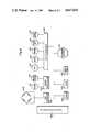
- strain gauge 108Also shown in FIG. 9 is a strain gauge 108. It will be recalled that strain gauge 108 was not shown in the earlier description of gauge assembly 44. As can now be more easily appreciated, it is the strain gauge 108 which is electrically attached to cantilevered strain beam 68. With this attachment the flexures of cantilevered strain beam 68 which are caused by the movement of pressure transmitting member 76 in response to variations in the outer diameter of pumping section 18 will be sensed by the strain gauge 108. Electronically, it can be appreciated that the analog voltage measurements obtained from strain gauge 108 represent a voltage which requires conversion by an A/D converter 110 before it is electrically compatible with microprocessor 100. As shown in FIG. 9, the ciruitry for this electrical connection is provided.
Landscapes
- Health & Medical Sciences (AREA)
- Vascular Medicine (AREA)
- Engineering & Computer Science (AREA)
- Anesthesiology (AREA)
- Biomedical Technology (AREA)
- Heart & Thoracic Surgery (AREA)
- Hematology (AREA)
- Life Sciences & Earth Sciences (AREA)
- Animal Behavior & Ethology (AREA)
- General Health & Medical Sciences (AREA)
- Public Health (AREA)
- Veterinary Medicine (AREA)
- Infusion, Injection, And Reservoir Apparatuses (AREA)
- Reciprocating Pumps (AREA)
Abstract
Description
Claims (20)
Priority Applications (12)
| Application Number | Priority Date | Filing Date | Title |
|---|---|---|---|
| US06/801,987US4617014A (en) | 1985-11-26 | 1985-11-26 | Dual mode I. V. infusion device |
| US06/844,414US4690673A (en) | 1985-11-26 | 1986-03-26 | Dual mode I.V. infusion device with distal sensor |
| AU61546/86AAU580184B2 (en) | 1985-11-26 | 1986-08-18 | Dual mode I.V. infusion device |
| CA000516747ACA1235033A (en) | 1985-11-26 | 1986-08-25 | Dual mode i.v. infusion device |
| JP61212885AJPS62127058A (en) | 1985-11-26 | 1986-09-11 | Vein dripping apparatus |
| CA000521358ACA1258212A (en) | 1985-11-26 | 1986-10-24 | Dual mode i.v. infusion device with distal sensor |
| AU64504/86AAU586594B2 (en) | 1985-11-26 | 1986-10-29 | Dual mode I.V. infusion device with distal sensor |
| JP61273829AJPS62176457A (en) | 1985-11-26 | 1986-11-17 | Vein dripping apparatus |
| EP86309194AEP0225158B1 (en) | 1985-11-26 | 1986-11-25 | Dual mode i.v. infusion device |
| DE8686309194TDE3686558T2 (en) | 1985-11-26 | 1986-11-25 | INTRAVENOUS INFUSION DEVICE WITH TWO APPLICATIONS. |
| DK565286ADK565286A (en) | 1985-11-26 | 1986-11-25 | INTRAVENOST INFUSION SYSTEM WITH TWO WORKS AND WITH A SENSOR DEVICE LOCATED IN THE OUTER |
| AT86309194TATE79771T1 (en) | 1985-11-26 | 1986-11-25 | INTRAVENOUS INFUSION DEVICE WITH TWO APPLICATIONS. |
Applications Claiming Priority (1)
| Application Number | Priority Date | Filing Date | Title |
|---|---|---|---|
| US06/801,987US4617014A (en) | 1985-11-26 | 1985-11-26 | Dual mode I. V. infusion device |
Related Child Applications (1)
| Application Number | Title | Priority Date | Filing Date |
|---|---|---|---|
| US06/844,414Continuation-In-PartUS4690673A (en) | 1985-11-26 | 1986-03-26 | Dual mode I.V. infusion device with distal sensor |
Publications (1)
| Publication Number | Publication Date |
|---|---|
| US4617014Atrue US4617014A (en) | 1986-10-14 |
Family
ID=25182542
Family Applications (1)
| Application Number | Title | Priority Date | Filing Date |
|---|---|---|---|
| US06/801,987Expired - LifetimeUS4617014A (en) | 1985-11-26 | 1985-11-26 | Dual mode I. V. infusion device |
Country Status (4)
| Country | Link |
|---|---|
| US (1) | US4617014A (en) |
| JP (2) | JPS62127058A (en) |
| AU (1) | AU580184B2 (en) |
| CA (1) | CA1235033A (en) |
Cited By (105)
| Publication number | Priority date | Publication date | Assignee | Title |
|---|---|---|---|---|
| US4690673A (en)* | 1985-11-26 | 1987-09-01 | Imed Corporation | Dual mode I.V. infusion device with distal sensor |
| US4710163A (en)* | 1986-06-06 | 1987-12-01 | Ivac Corporation | Detection of fluid flow faults in the parenteral administration of fluids |
| US4731057A (en)* | 1985-08-05 | 1988-03-15 | Nikkiso Co., Ltd. | Transfusion apparatus |
| US4747828A (en)* | 1986-12-09 | 1988-05-31 | Fisher Scientific Group | IV fluid line occlusion detector |
| US4755109A (en)* | 1987-04-03 | 1988-07-05 | Fisher Scientific Company Inc. | Snap-together peristaltic mechanism |
| US4764166A (en)* | 1987-08-17 | 1988-08-16 | Fisher Scientific Company | Ultrasonic air-in-line detector |
| EP0283614A1 (en)* | 1987-02-24 | 1988-09-28 | Imed Corporation | Apparatus for pumping fluids through a tube |
| US4836752A (en)* | 1987-11-02 | 1989-06-06 | Fisher Scientific Company | Partial restriction detector |
| US4854836A (en)* | 1986-02-18 | 1989-08-08 | Baxter International Inc. | Collapsible conduit for linear peristaltic pump and method of making the same |
| US4857048A (en)* | 1987-05-29 | 1989-08-15 | Hewlett-Packard Company | IV pump and disposable flow chamber with flow control |
| US4867744A (en)* | 1987-05-21 | 1989-09-19 | Baxter International Inc. | Peristaltic linear pump with contoured rollers |
| EP0319267A3 (en)* | 1987-12-04 | 1989-11-29 | Pacesetter Infusion Limited Doing Business As Minimed Technologies | Fluid delivery control and monitoring apparatus |
| US4976687A (en)* | 1987-05-11 | 1990-12-11 | James Martin | Apparatus for controlling the supplying of intravenous fluids |
| AU604457B2 (en)* | 1988-06-09 | 1990-12-13 | Imed Corporation | Dual roller peristaltic pump |
| US5018945A (en)* | 1989-12-14 | 1991-05-28 | Baxter International Inc. | Accurate peristaltic pump |
| US5047014A (en)* | 1989-04-15 | 1991-09-10 | B. Braun Melsungen Ag | Medical pump device |
| US5096385A (en)* | 1989-11-08 | 1992-03-17 | Ivac Corporation | Method and system for upstream occlusion detection |
| US5103211A (en)* | 1989-11-02 | 1992-04-07 | Ivac Corporation | Apparatus for detecting fluid line occlusion |
| EP0526962A1 (en)* | 1991-08-05 | 1993-02-10 | Imed Corporation | Two-cycle peristaltic pump with occlusion detector |
| EP0527868A4 (en)* | 1990-05-04 | 1993-09-22 | Block Medical, Inc. | Disposable infusion apparatus with peristaltic pump |
| US5263830A (en)* | 1991-01-23 | 1993-11-23 | Sharp Kabushiki Kaisha | Peristaltic pump assembly |
| US5320503A (en) | 1988-05-17 | 1994-06-14 | Patient Solutions Inc. | Infusion device with disposable elements |
| US5356378A (en)* | 1992-01-22 | 1994-10-18 | Ivac Corporation | Fluid line condition detection |
| US5395320A (en)* | 1992-06-09 | 1995-03-07 | Sabratek Corporation | Programmable infusion pump with interchangeable tubing |
| US5531698A (en)* | 1994-04-15 | 1996-07-02 | Sims Deltec, Inc. | Optical reflection systems and methods for cassette identification fordrug pumps |
| US5554115A (en)* | 1995-04-07 | 1996-09-10 | Abbott Laboratories | Sensor for measuring pressures in a cassette pump proximal and distal to a pumping chamber |
| US5584667A (en) | 1988-05-17 | 1996-12-17 | Davis; David L. | Method of providing uniform flow from an infusion device |
| USD376848S (en) | 1995-03-06 | 1996-12-24 | Sabratek Corporation | Infusion pump cassette |
| US5609575A (en)* | 1994-04-11 | 1997-03-11 | Graseby Medical Limited | Infusion pump and method with dose-rate calculation |
| US5620312A (en)* | 1995-03-06 | 1997-04-15 | Sabratek Corporation | Infusion pump with dual-latching mechanism |
| US5628619A (en)* | 1995-03-06 | 1997-05-13 | Sabratek Corporation | Infusion pump having power-saving modes |
| US5637093A (en)* | 1995-03-06 | 1997-06-10 | Sabratek Corporation | Infusion pump with selective backlight |
| USD380260S (en)* | 1995-03-06 | 1997-06-24 | Sabratek Corporation | Infusion pump |
| US5660529A (en)* | 1994-12-06 | 1997-08-26 | Mcgaw, Inc. | Linear peristaltic pump with reshaping fingers interdigitated with pumping elements |
| US5695473A (en)* | 1994-07-27 | 1997-12-09 | Sims Deltec, Inc. | Occlusion detection system for an infusion pump |
| US5795327A (en)* | 1995-03-06 | 1998-08-18 | Sabratek Corporation | Infusion pump with historical data recording |
| US5803712A (en) | 1988-05-17 | 1998-09-08 | Patient Solutions, Inc. | Method of measuring an occlusion in an infusion device with disposable elements |
| US5807322A (en)* | 1994-03-21 | 1998-09-15 | Graseby Medical Limited | Pumping and pressure detection using flexible tubes |
| US5827223A (en)* | 1995-08-31 | 1998-10-27 | Alaris Medical Systems, Inc. | Upstream occulsion detection system |
| US5853386A (en)* | 1996-07-25 | 1998-12-29 | Alaris Medical Systems, Inc. | Infusion device with disposable elements |
| US5904668A (en)* | 1995-03-06 | 1999-05-18 | Sabratek Corporation | Cassette for an infusion pump |
| US5935099A (en)* | 1992-09-09 | 1999-08-10 | Sims Deltec, Inc. | Drug pump systems and methods |
| EP0959920A4 (en)* | 1995-05-05 | 1999-12-01 | ||
| US6077055A (en)* | 1998-12-03 | 2000-06-20 | Sims Deltec, Inc. | Pump system including cassette sensor and occlusion sensor |
| US6234773B1 (en) | 1994-12-06 | 2001-05-22 | B-Braun Medical, Inc. | Linear peristaltic pump with reshaping fingers interdigitated with pumping elements |
| US6293758B1 (en) | 1998-07-15 | 2001-09-25 | Bredel Hose Pumps B.V. | Peristaltic pump provided with a pressure measurement device to monitor the condition of the hose |
| US20020127114A1 (en)* | 2001-01-28 | 2002-09-12 | Swi Barak | Liquid pump |
| US6468242B1 (en) | 1998-03-06 | 2002-10-22 | Baxter International Inc. | Medical apparatus with patient data recording |
| US20020177821A1 (en)* | 2001-04-04 | 2002-11-28 | Swi Barak | Flow set and a method for identifying the flow set for use with a pump |
| US20030214412A1 (en)* | 2002-05-20 | 2003-11-20 | B. Braun Medical, Inc. | Proper tubing installation testing method and apparatus for a peristaltic pump |
| US20050145010A1 (en)* | 2003-12-31 | 2005-07-07 | Vanderveen Timothy W. | Medication safety enhancement for secondary infusion |
| US20050145008A1 (en)* | 2003-12-31 | 2005-07-07 | Vanderveen Timothy W. | System for detecting the status of a vent associated with a fluid supply upstream of an infusion pump |
| US20050145009A1 (en)* | 2003-12-31 | 2005-07-07 | Vanderveen Timothy W. | Empty container detection using container side pressure sensing |
| US20050214129A1 (en)* | 2004-03-26 | 2005-09-29 | Greene Howard L | Medical infusion pump with closed loop stroke feedback system and method |
| US20070058412A1 (en)* | 2004-03-26 | 2007-03-15 | Wang David T | System and method for improved low flow medical pump delivery |
| US20080015505A1 (en)* | 2001-07-10 | 2008-01-17 | Medrad, Inc. | Infusion pump system for use in mri suites |
| US7347836B2 (en) | 1992-09-09 | 2008-03-25 | Smiths Medical, Inc. | Drug pump systems and methods |
| US20090016915A1 (en)* | 2005-03-30 | 2009-01-15 | Medical Service S.R.L. | Pump, especially for the blood treatment |
| US20110046558A1 (en)* | 2009-08-18 | 2011-02-24 | Peter Gravesen | Medicine delivery device having detachable pressure sensing unit |
| US20110043357A1 (en)* | 2009-08-18 | 2011-02-24 | Greg Peatfield | Methods for detecting failure states in a medicine delivery device |
| US20110318198A1 (en)* | 2010-06-23 | 2011-12-29 | Hospira, Inc. | Fluid Flow Rate Compensation System Using an Integrated Conductivity Sensor to Monitor Tubing Changes |
| US8133197B2 (en) | 2008-05-02 | 2012-03-13 | Smiths Medical Asd, Inc. | Display for pump |
| US8149131B2 (en) | 2006-08-03 | 2012-04-03 | Smiths Medical Asd, Inc. | Interface for medical infusion pump |
| US8250483B2 (en) | 2002-02-28 | 2012-08-21 | Smiths Medical Asd, Inc. | Programmable medical infusion pump displaying a banner |
| WO2012094348A3 (en)* | 2011-01-06 | 2012-09-20 | Carefusion 303, Inc. | An iv pump adapted for generic tubing |
| US8435206B2 (en) | 2006-08-03 | 2013-05-07 | Smiths Medical Asd, Inc. | Interface for medical infusion pump |
| US8504179B2 (en) | 2002-02-28 | 2013-08-06 | Smiths Medical Asd, Inc. | Programmable medical infusion pump |
| WO2013175115A1 (en)* | 2012-05-23 | 2013-11-28 | Physidia | Linear peristaltic pump |
| CN101644567B (en)* | 2008-08-04 | 2014-02-26 | 北京谊安医疗系统股份有限公司 | Method and device for identifying and monitoring injector and injection pump adopting method and device |
| US8858526B2 (en) | 2006-08-03 | 2014-10-14 | Smiths Medical Asd, Inc. | Interface for medical infusion pump |
| US8954336B2 (en) | 2004-02-23 | 2015-02-10 | Smiths Medical Asd, Inc. | Server for medical device |
| US8965707B2 (en) | 2006-08-03 | 2015-02-24 | Smiths Medical Asd, Inc. | Interface for medical infusion pump |
| CN104415417A (en)* | 2013-08-20 | 2015-03-18 | 肖进 | Infusion pump peristaltic device with elastic check valve |
| US9005169B2 (en) | 2007-10-16 | 2015-04-14 | Cequr Sa | Cannula insertion device and related methods |
| US9211378B2 (en) | 2010-10-22 | 2015-12-15 | Cequr Sa | Methods and systems for dosing a medicament |
| US10022498B2 (en) | 2011-12-16 | 2018-07-17 | Icu Medical, Inc. | System for monitoring and delivering medication to a patient and method of using the same to minimize the risks associated with automated therapy |
| US10166328B2 (en) | 2013-05-29 | 2019-01-01 | Icu Medical, Inc. | Infusion system which utilizes one or more sensors and additional information to make an air determination regarding the infusion system |
| US10220132B2 (en) | 2014-12-19 | 2019-03-05 | Fenwal, Inc. | Biological fluid flow control apparatus and method |
| US10342917B2 (en) | 2014-02-28 | 2019-07-09 | Icu Medical, Inc. | Infusion system and method which utilizes dual wavelength optical air-in-line detection |
| US10430761B2 (en) | 2011-08-19 | 2019-10-01 | Icu Medical, Inc. | Systems and methods for a graphical interface including a graphical representation of medical data |
| US10463788B2 (en) | 2012-07-31 | 2019-11-05 | Icu Medical, Inc. | Patient care system for critical medications |
| US10578474B2 (en) | 2012-03-30 | 2020-03-03 | Icu Medical, Inc. | Air detection system and method for detecting air in a pump of an infusion system |
| US10596316B2 (en) | 2013-05-29 | 2020-03-24 | Icu Medical, Inc. | Infusion system and method of use which prevents over-saturation of an analog-to-digital converter |
| WO2020079236A1 (en)* | 2018-10-19 | 2020-04-23 | F. Hoffmann-La Roche Ag | Microdosing |
| US10635784B2 (en) | 2007-12-18 | 2020-04-28 | Icu Medical, Inc. | User interface improvements for medical devices |
| US10656894B2 (en) | 2017-12-27 | 2020-05-19 | Icu Medical, Inc. | Synchronized display of screen content on networked devices |
| US10682460B2 (en) | 2013-01-28 | 2020-06-16 | Smiths Medical Asd, Inc. | Medication safety devices and methods |
| US10850024B2 (en) | 2015-03-02 | 2020-12-01 | Icu Medical, Inc. | Infusion system, device, and method having advanced infusion features |
| US10874793B2 (en) | 2013-05-24 | 2020-12-29 | Icu Medical, Inc. | Multi-sensor infusion system for detecting air or an occlusion in the infusion system |
| US11135360B1 (en) | 2020-12-07 | 2021-10-05 | Icu Medical, Inc. | Concurrent infusion with common line auto flush |
| US20210369954A1 (en)* | 2017-12-19 | 2021-12-02 | Smiths Medical Asd, Inc. | Infusion pump systems and methods for administration sets |
| US11246985B2 (en) | 2016-05-13 | 2022-02-15 | Icu Medical, Inc. | Infusion pump system and method with common line auto flush |
| US11278671B2 (en) | 2019-12-04 | 2022-03-22 | Icu Medical, Inc. | Infusion pump with safety sequence keypad |
| US11324888B2 (en) | 2016-06-10 | 2022-05-10 | Icu Medical, Inc. | Acoustic flow sensor for continuous medication flow measurements and feedback control of infusion |
| US11344673B2 (en) | 2014-05-29 | 2022-05-31 | Icu Medical, Inc. | Infusion system and pump with configurable closed loop delivery rate catch-up |
| US11344668B2 (en) | 2014-12-19 | 2022-05-31 | Icu Medical, Inc. | Infusion system with concurrent TPN/insulin infusion |
| US11484645B2 (en) | 2020-11-18 | 2022-11-01 | Perceptive Medical Inc. | Systems and components for regulating fluid infusion to a patient |
| US20220379014A1 (en)* | 2021-06-01 | 2022-12-01 | Amf Medical Sa | Systems and methods for delivering microdoses of medication |
| US11529458B2 (en) | 2017-12-08 | 2022-12-20 | Amf Medical Sa | Drug delivery device |
| US11679199B2 (en) | 2021-06-01 | 2023-06-20 | Amf Medical Sa | Systems and methods for delivering microdoses of medication |
| US11806502B2 (en) | 2015-11-20 | 2023-11-07 | Tandem Diabetes Care Switzerland Sarl | Micropump |
| US11857757B2 (en) | 2021-06-01 | 2024-01-02 | Tandem Diabetes Care Switzerland Sàrl | Systems and methods for delivering microdoses of medication |
| US11883361B2 (en) | 2020-07-21 | 2024-01-30 | Icu Medical, Inc. | Fluid transfer devices and methods of use |
| US12350233B2 (en) | 2021-12-10 | 2025-07-08 | Icu Medical, Inc. | Medical fluid compounding systems with coordinated flow control |
| USD1091564S1 (en) | 2021-10-13 | 2025-09-02 | Icu Medical, Inc. | Display screen or portion thereof with graphical user interface for a medical device |
Families Citing this family (4)
| Publication number | Priority date | Publication date | Assignee | Title |
|---|---|---|---|---|
| JP2510908B2 (en)* | 1991-07-31 | 1996-06-26 | アトムメディカル株式会社 | Medical liquid pump |
| CA2083555A1 (en)* | 1992-11-23 | 1994-05-24 | David H. Laing | Portable infusion device |
| US20150182697A1 (en)* | 2013-12-31 | 2015-07-02 | Abbvie Inc. | Pump, motor and assembly for beneficial agent delivery |
| CN106730154A (en)* | 2016-12-13 | 2017-05-31 | 安徽乐年健康养老产业有限公司 | A kind of automatic infusion monitor with alarm and method |
Citations (18)
| Publication number | Priority date | Publication date | Assignee | Title |
|---|---|---|---|---|
| US2420148A (en)* | 1943-11-08 | 1947-05-06 | Douglas Aircraft Co Inc | Pressure indicator |
| US2770703A (en)* | 1953-05-28 | 1956-11-13 | Northern Pump Company | Transducer |
| US2885520A (en)* | 1957-01-07 | 1959-05-05 | Statham Instrument Inc | Pressure transducer |
| US3218864A (en)* | 1962-08-07 | 1965-11-23 | Honeywell Inc | Force ratio apparatus |
| US3505634A (en)* | 1967-11-21 | 1970-04-07 | George Von Vick | Differential pressure transducer |
| US3778195A (en)* | 1972-07-20 | 1973-12-11 | G Bamberg | Pump for parenteral injections and the like |
| US3866473A (en)* | 1969-08-04 | 1975-02-18 | Bendix Corp | Pressure measuring transducer |
| US4306460A (en)* | 1978-12-22 | 1981-12-22 | Hitachi, Ltd. | Differential pressure transducer |
| US4309908A (en)* | 1979-09-01 | 1982-01-12 | Hottinger Baldwin Measurements, Inc. | Liquid filled pressure transducer |
| US4345476A (en)* | 1980-07-25 | 1982-08-24 | Bourns Instruments, Inc. | Differential pressure transducer with high compliance, constant stress cantilever beam |
| US4346705A (en)* | 1980-10-09 | 1982-08-31 | Baxter Travenol Laboratories, Inc. | Metering apparatus having rate compensation circuit |
| US4373525A (en)* | 1980-02-12 | 1983-02-15 | Terumo Corporation | Method and apparatus for detecting occlusion in fluid-infusion tube of peristaltic type fluid-infusion pump |
| US4394862A (en)* | 1980-08-25 | 1983-07-26 | Baxter Travenol Laboratories, Inc. | Metering apparatus with downline pressure monitoring system |
| US4468219A (en)* | 1983-12-20 | 1984-08-28 | International Business Machines Corporation | Pump flow rate compensation system |
| US4479797A (en)* | 1981-07-04 | 1984-10-30 | Terumo Corporation | Medication infusion device |
| US4493706A (en)* | 1982-08-12 | 1985-01-15 | American Hospital Supply Corporation | Linear peristaltic pumping apparatus and disposable casette therefor |
| US4526574A (en)* | 1983-05-23 | 1985-07-02 | Baxter Travenol Laboratories, Inc. | Differential occlusion sensing method and apparatus |
| US4563179A (en)* | 1982-04-28 | 1986-01-07 | Sharp Kabushiki Kaisha | Blocking condition detection device in a fluid injection system |
Family Cites Families (1)
| Publication number | Priority date | Publication date | Assignee | Title |
|---|---|---|---|---|
| US4460355A (en)* | 1982-06-11 | 1984-07-17 | Ivac Corporation | Fluid pressure monitoring system |
- 1985
- 1985-11-26USUS06/801,987patent/US4617014A/ennot_activeExpired - Lifetime
- 1986
- 1986-08-18AUAU61546/86Apatent/AU580184B2/ennot_activeCeased
- 1986-08-25CACA000516747Apatent/CA1235033A/ennot_activeExpired
- 1986-09-11JPJP61212885Apatent/JPS62127058A/enactiveGranted
- 1986-11-17JPJP61273829Apatent/JPS62176457A/enactiveGranted
Patent Citations (18)
| Publication number | Priority date | Publication date | Assignee | Title |
|---|---|---|---|---|
| US2420148A (en)* | 1943-11-08 | 1947-05-06 | Douglas Aircraft Co Inc | Pressure indicator |
| US2770703A (en)* | 1953-05-28 | 1956-11-13 | Northern Pump Company | Transducer |
| US2885520A (en)* | 1957-01-07 | 1959-05-05 | Statham Instrument Inc | Pressure transducer |
| US3218864A (en)* | 1962-08-07 | 1965-11-23 | Honeywell Inc | Force ratio apparatus |
| US3505634A (en)* | 1967-11-21 | 1970-04-07 | George Von Vick | Differential pressure transducer |
| US3866473A (en)* | 1969-08-04 | 1975-02-18 | Bendix Corp | Pressure measuring transducer |
| US3778195A (en)* | 1972-07-20 | 1973-12-11 | G Bamberg | Pump for parenteral injections and the like |
| US4306460A (en)* | 1978-12-22 | 1981-12-22 | Hitachi, Ltd. | Differential pressure transducer |
| US4309908A (en)* | 1979-09-01 | 1982-01-12 | Hottinger Baldwin Measurements, Inc. | Liquid filled pressure transducer |
| US4373525A (en)* | 1980-02-12 | 1983-02-15 | Terumo Corporation | Method and apparatus for detecting occlusion in fluid-infusion tube of peristaltic type fluid-infusion pump |
| US4345476A (en)* | 1980-07-25 | 1982-08-24 | Bourns Instruments, Inc. | Differential pressure transducer with high compliance, constant stress cantilever beam |
| US4394862A (en)* | 1980-08-25 | 1983-07-26 | Baxter Travenol Laboratories, Inc. | Metering apparatus with downline pressure monitoring system |
| US4346705A (en)* | 1980-10-09 | 1982-08-31 | Baxter Travenol Laboratories, Inc. | Metering apparatus having rate compensation circuit |
| US4479797A (en)* | 1981-07-04 | 1984-10-30 | Terumo Corporation | Medication infusion device |
| US4563179A (en)* | 1982-04-28 | 1986-01-07 | Sharp Kabushiki Kaisha | Blocking condition detection device in a fluid injection system |
| US4493706A (en)* | 1982-08-12 | 1985-01-15 | American Hospital Supply Corporation | Linear peristaltic pumping apparatus and disposable casette therefor |
| US4526574A (en)* | 1983-05-23 | 1985-07-02 | Baxter Travenol Laboratories, Inc. | Differential occlusion sensing method and apparatus |
| US4468219A (en)* | 1983-12-20 | 1984-08-28 | International Business Machines Corporation | Pump flow rate compensation system |
Cited By (190)
| Publication number | Priority date | Publication date | Assignee | Title |
|---|---|---|---|---|
| US4731057A (en)* | 1985-08-05 | 1988-03-15 | Nikkiso Co., Ltd. | Transfusion apparatus |
| US4690673A (en)* | 1985-11-26 | 1987-09-01 | Imed Corporation | Dual mode I.V. infusion device with distal sensor |
| US4854836A (en)* | 1986-02-18 | 1989-08-08 | Baxter International Inc. | Collapsible conduit for linear peristaltic pump and method of making the same |
| US4710163A (en)* | 1986-06-06 | 1987-12-01 | Ivac Corporation | Detection of fluid flow faults in the parenteral administration of fluids |
| US4747828A (en)* | 1986-12-09 | 1988-05-31 | Fisher Scientific Group | IV fluid line occlusion detector |
| EP0283614A1 (en)* | 1987-02-24 | 1988-09-28 | Imed Corporation | Apparatus for pumping fluids through a tube |
| US4755109A (en)* | 1987-04-03 | 1988-07-05 | Fisher Scientific Company Inc. | Snap-together peristaltic mechanism |
| US4976687A (en)* | 1987-05-11 | 1990-12-11 | James Martin | Apparatus for controlling the supplying of intravenous fluids |
| US4867744A (en)* | 1987-05-21 | 1989-09-19 | Baxter International Inc. | Peristaltic linear pump with contoured rollers |
| US4857048A (en)* | 1987-05-29 | 1989-08-15 | Hewlett-Packard Company | IV pump and disposable flow chamber with flow control |
| US4764166A (en)* | 1987-08-17 | 1988-08-16 | Fisher Scientific Company | Ultrasonic air-in-line detector |
| US4836752A (en)* | 1987-11-02 | 1989-06-06 | Fisher Scientific Company | Partial restriction detector |
| EP0319267A3 (en)* | 1987-12-04 | 1989-11-29 | Pacesetter Infusion Limited Doing Business As Minimed Technologies | Fluid delivery control and monitoring apparatus |
| US5320503A (en) | 1988-05-17 | 1994-06-14 | Patient Solutions Inc. | Infusion device with disposable elements |
| US5803712A (en) | 1988-05-17 | 1998-09-08 | Patient Solutions, Inc. | Method of measuring an occlusion in an infusion device with disposable elements |
| US5584667A (en) | 1988-05-17 | 1996-12-17 | Davis; David L. | Method of providing uniform flow from an infusion device |
| US6742992B2 (en) | 1988-05-17 | 2004-06-01 | I-Flow Corporation | Infusion device with disposable elements |
| US6312227B1 (en) | 1988-05-17 | 2001-11-06 | I-Flow Corp. | Infusion device with disposable elements |
| US6146109A (en) | 1988-05-17 | 2000-11-14 | Alaris Medical Systems, Inc. | Infusion device with disposable elements |
| AU604457B2 (en)* | 1988-06-09 | 1990-12-13 | Imed Corporation | Dual roller peristaltic pump |
| US5047014A (en)* | 1989-04-15 | 1991-09-10 | B. Braun Melsungen Ag | Medical pump device |
| US5103211A (en)* | 1989-11-02 | 1992-04-07 | Ivac Corporation | Apparatus for detecting fluid line occlusion |
| US5096385A (en)* | 1989-11-08 | 1992-03-17 | Ivac Corporation | Method and system for upstream occlusion detection |
| US5018945A (en)* | 1989-12-14 | 1991-05-28 | Baxter International Inc. | Accurate peristaltic pump |
| EP0527868A4 (en)* | 1990-05-04 | 1993-09-22 | Block Medical, Inc. | Disposable infusion apparatus with peristaltic pump |
| US5263830A (en)* | 1991-01-23 | 1993-11-23 | Sharp Kabushiki Kaisha | Peristaltic pump assembly |
| US5217355A (en)* | 1991-08-05 | 1993-06-08 | Imed Corporation | Two-cycle peristaltic pump with occlusion detector |
| EP0526962A1 (en)* | 1991-08-05 | 1993-02-10 | Imed Corporation | Two-cycle peristaltic pump with occlusion detector |
| US5356378A (en)* | 1992-01-22 | 1994-10-18 | Ivac Corporation | Fluid line condition detection |
| US5395320A (en)* | 1992-06-09 | 1995-03-07 | Sabratek Corporation | Programmable infusion pump with interchangeable tubing |
| US7347836B2 (en) | 1992-09-09 | 2008-03-25 | Smiths Medical, Inc. | Drug pump systems and methods |
| US5935099A (en)* | 1992-09-09 | 1999-08-10 | Sims Deltec, Inc. | Drug pump systems and methods |
| US7654976B2 (en) | 1992-09-09 | 2010-02-02 | Smiths Medical Asd, Inc. | Drug pump systems and methods |
| US5807322A (en)* | 1994-03-21 | 1998-09-15 | Graseby Medical Limited | Pumping and pressure detection using flexible tubes |
| US5609575A (en)* | 1994-04-11 | 1997-03-11 | Graseby Medical Limited | Infusion pump and method with dose-rate calculation |
| US5531697A (en)* | 1994-04-15 | 1996-07-02 | Sims Deltec, Inc. | Systems and methods for cassette identification for drug pumps |
| US5531698A (en)* | 1994-04-15 | 1996-07-02 | Sims Deltec, Inc. | Optical reflection systems and methods for cassette identification fordrug pumps |
| US6123686A (en)* | 1994-04-15 | 2000-09-26 | Sims Deltec, Inc. | Systems and methods for cassette identification for drug pumps |
| US5647854A (en)* | 1994-04-15 | 1997-07-15 | Sims Deltec, Inc. | Base plate for a drug pump |
| US5695473A (en)* | 1994-07-27 | 1997-12-09 | Sims Deltec, Inc. | Occlusion detection system for an infusion pump |
| US5660529A (en)* | 1994-12-06 | 1997-08-26 | Mcgaw, Inc. | Linear peristaltic pump with reshaping fingers interdigitated with pumping elements |
| US6234773B1 (en) | 1994-12-06 | 2001-05-22 | B-Braun Medical, Inc. | Linear peristaltic pump with reshaping fingers interdigitated with pumping elements |
| US5888052A (en)* | 1994-12-06 | 1999-03-30 | Mcgraw, Inc. | Linear peristaltic pump with reshaping fingers intedigitated with pumping elements |
| US5628619A (en)* | 1995-03-06 | 1997-05-13 | Sabratek Corporation | Infusion pump having power-saving modes |
| US5637093A (en)* | 1995-03-06 | 1997-06-10 | Sabratek Corporation | Infusion pump with selective backlight |
| USD380260S (en)* | 1995-03-06 | 1997-06-24 | Sabratek Corporation | Infusion pump |
| US5904668A (en)* | 1995-03-06 | 1999-05-18 | Sabratek Corporation | Cassette for an infusion pump |
| US5620312A (en)* | 1995-03-06 | 1997-04-15 | Sabratek Corporation | Infusion pump with dual-latching mechanism |
| US5993420A (en)* | 1995-03-06 | 1999-11-30 | Sabratek Corporation | Cassette for an infusion pump |
| USD376848S (en) | 1995-03-06 | 1996-12-24 | Sabratek Corporation | Infusion pump cassette |
| US5795327A (en)* | 1995-03-06 | 1998-08-18 | Sabratek Corporation | Infusion pump with historical data recording |
| US5791880A (en)* | 1995-03-06 | 1998-08-11 | Sabratek Corporation | Infusion pump having power-saving modes |
| US5766155A (en)* | 1995-03-06 | 1998-06-16 | Sabratek Corporation | Infusion pump with selective backlight |
| US5554115A (en)* | 1995-04-07 | 1996-09-10 | Abbott Laboratories | Sensor for measuring pressures in a cassette pump proximal and distal to a pumping chamber |
| EP0959920A4 (en)* | 1995-05-05 | 1999-12-01 | ||
| US5827223A (en)* | 1995-08-31 | 1998-10-27 | Alaris Medical Systems, Inc. | Upstream occulsion detection system |
| US6358225B1 (en) | 1995-08-31 | 2002-03-19 | Alaris Medical Systems, Inc. | Upstream occlusion detection system |
| US6110153A (en)* | 1996-07-25 | 2000-08-29 | Alaris Medical Systems, Inc. | Infusion device with optical sensor |
| US5853386A (en)* | 1996-07-25 | 1998-12-29 | Alaris Medical Systems, Inc. | Infusion device with disposable elements |
| US6468242B1 (en) | 1998-03-06 | 2002-10-22 | Baxter International Inc. | Medical apparatus with patient data recording |
| US6293758B1 (en) | 1998-07-15 | 2001-09-25 | Bredel Hose Pumps B.V. | Peristaltic pump provided with a pressure measurement device to monitor the condition of the hose |
| US6077055A (en)* | 1998-12-03 | 2000-06-20 | Sims Deltec, Inc. | Pump system including cassette sensor and occlusion sensor |
| US6881043B2 (en)* | 2001-01-28 | 2005-04-19 | Medrad, Inc. | Injection apparatus incorporating clamping and squeezing members for pumping liquid through flexible tubing |
| US20020127114A1 (en)* | 2001-01-28 | 2002-09-12 | Swi Barak | Liquid pump |
| US8025654B2 (en) | 2001-04-04 | 2011-09-27 | Medrad, Inc. | Method of identifying a flow set for use with a pump |
| US20080208124A1 (en)* | 2001-04-04 | 2008-08-28 | Caesarea Medical Electronics Ltd. | Method of identifying a flow set for use with a pump |
| US7384408B2 (en) | 2001-04-04 | 2008-06-10 | Caesarea Medical Electronics Ltd. | Flow set including an identifying key member having two projections cooperating to define a unique code |
| US20020177821A1 (en)* | 2001-04-04 | 2002-11-28 | Swi Barak | Flow set and a method for identifying the flow set for use with a pump |
| US20080015505A1 (en)* | 2001-07-10 | 2008-01-17 | Medrad, Inc. | Infusion pump system for use in mri suites |
| US7540854B2 (en) | 2001-07-10 | 2009-06-02 | Medrad, Inc. | Method of substituting a first fluid delivery device with a second fluid delivery device |
| US8504179B2 (en) | 2002-02-28 | 2013-08-06 | Smiths Medical Asd, Inc. | Programmable medical infusion pump |
| US8250483B2 (en) | 2002-02-28 | 2012-08-21 | Smiths Medical Asd, Inc. | Programmable medical infusion pump displaying a banner |
| US6731216B2 (en) | 2002-05-20 | 2004-05-04 | B. Braun Medical, Inc. | Proper tubing installation testing method and apparatus for a peristaltic pump |
| US20030214412A1 (en)* | 2002-05-20 | 2003-11-20 | B. Braun Medical, Inc. | Proper tubing installation testing method and apparatus for a peristaltic pump |
| US20070271062A1 (en)* | 2003-12-31 | 2007-11-22 | Vanderveen Timothy W | Empty container detection using container side pressure sensing |
| US20050145009A1 (en)* | 2003-12-31 | 2005-07-07 | Vanderveen Timothy W. | Empty container detection using container side pressure sensing |
| US7255683B2 (en) | 2003-12-31 | 2007-08-14 | Cardinal Health 303, Inc. | System for detecting the status of a vent associated with a fluid supply upstream of an infusion pump |
| US7206715B2 (en) | 2003-12-31 | 2007-04-17 | Cardinal Health 303, Inc. | Empty container detection using container side pressure sensing |
| US9039656B2 (en) | 2003-12-31 | 2015-05-26 | Carefusion 303, Inc. | Medication safety enhancement for secondary infusion |
| US20050145010A1 (en)* | 2003-12-31 | 2005-07-07 | Vanderveen Timothy W. | Medication safety enhancement for secondary infusion |
| US7561986B2 (en) | 2003-12-31 | 2009-07-14 | Cardinal Health 303, Inc. | Empty container detection using container side pressure sensing |
| US20070274843A1 (en)* | 2003-12-31 | 2007-11-29 | Cardinal Health 303, Inc. | System for detecting the status of a vent associated with a fluid supply upstream of an infusion pump |
| US8672875B2 (en) | 2003-12-31 | 2014-03-18 | Carefusion 303, Inc. | Medication safety enhancement for secondary infusion |
| US20050145008A1 (en)* | 2003-12-31 | 2005-07-07 | Vanderveen Timothy W. | System for detecting the status of a vent associated with a fluid supply upstream of an infusion pump |
| US8954336B2 (en) | 2004-02-23 | 2015-02-10 | Smiths Medical Asd, Inc. | Server for medical device |
| US20050214129A1 (en)* | 2004-03-26 | 2005-09-29 | Greene Howard L | Medical infusion pump with closed loop stroke feedback system and method |
| US7905710B2 (en) | 2004-03-26 | 2011-03-15 | Hospira, Inc. | System and method for improved low flow medical pump delivery |
| US20070058412A1 (en)* | 2004-03-26 | 2007-03-15 | Wang David T | System and method for improved low flow medical pump delivery |
| US8313308B2 (en) | 2004-03-26 | 2012-11-20 | Hospira, Inc. | Medical infusion pump with closed loop stroke feedback system and method |
| US8545197B2 (en)* | 2005-03-30 | 2013-10-01 | Medical Service S.R.L. | Pump, especially for blood treatment |
| US20090016915A1 (en)* | 2005-03-30 | 2009-01-15 | Medical Service S.R.L. | Pump, especially for the blood treatment |
| US8858526B2 (en) | 2006-08-03 | 2014-10-14 | Smiths Medical Asd, Inc. | Interface for medical infusion pump |
| US10255408B2 (en) | 2006-08-03 | 2019-04-09 | Smiths Medical Asd, Inc. | Interface for medical infusion pump |
| US8149131B2 (en) | 2006-08-03 | 2012-04-03 | Smiths Medical Asd, Inc. | Interface for medical infusion pump |
| US8965707B2 (en) | 2006-08-03 | 2015-02-24 | Smiths Medical Asd, Inc. | Interface for medical infusion pump |
| US10437963B2 (en) | 2006-08-03 | 2019-10-08 | Smiths Medical Asd, Inc. | Interface for medical infusion pump |
| US8952794B2 (en) | 2006-08-03 | 2015-02-10 | Smiths Medical Asd, Inc. | Interface for medical infusion pump |
| US8435206B2 (en) | 2006-08-03 | 2013-05-07 | Smiths Medical Asd, Inc. | Interface for medical infusion pump |
| US9740829B2 (en) | 2006-08-03 | 2017-08-22 | Smiths Medical Asd, Inc. | Interface for medical infusion pump |
| US9968747B2 (en) | 2007-10-16 | 2018-05-15 | Cequr Sa | Cannula insertion device and related methods |
| US9005169B2 (en) | 2007-10-16 | 2015-04-14 | Cequr Sa | Cannula insertion device and related methods |
| US10635784B2 (en) | 2007-12-18 | 2020-04-28 | Icu Medical, Inc. | User interface improvements for medical devices |
| US11488549B2 (en) | 2008-05-02 | 2022-11-01 | Tandem Diabetes Care, Inc. | Display for pump |
| US11580918B2 (en) | 2008-05-02 | 2023-02-14 | Tandem Diabetes Care, Inc. | Display for pump |
| US10726100B2 (en) | 2008-05-02 | 2020-07-28 | Tandem Diabetes Care, Inc. | Display for pump |
| US8133197B2 (en) | 2008-05-02 | 2012-03-13 | Smiths Medical Asd, Inc. | Display for pump |
| CN101644567B (en)* | 2008-08-04 | 2014-02-26 | 北京谊安医疗系统股份有限公司 | Method and device for identifying and monitoring injector and injection pump adopting method and device |
| US10226588B2 (en) | 2009-08-18 | 2019-03-12 | Cequr Sa | Methods for detecting failure states in a medicine delivery device |
| US8672873B2 (en) | 2009-08-18 | 2014-03-18 | Cequr Sa | Medicine delivery device having detachable pressure sensing unit |
| US9039654B2 (en) | 2009-08-18 | 2015-05-26 | Cequr Sa | Medicine delivery device having detachable pressure sensing unit |
| US8547239B2 (en) | 2009-08-18 | 2013-10-01 | Cequr Sa | Methods for detecting failure states in a medicine delivery device |
| US9174009B2 (en) | 2009-08-18 | 2015-11-03 | Cequr Sa | Methods for detecting failure states in a medicine delivery device |
| US9022972B2 (en) | 2009-08-18 | 2015-05-05 | Cequr Sa | Medicine delivery device having detachable pressure sensing unit |
| US10300196B2 (en) | 2009-08-18 | 2019-05-28 | Cequr Sa | Medicine delivery device having detachable pressure sensing unit |
| US9694147B2 (en) | 2009-08-18 | 2017-07-04 | Cequr Sa | Methods for detecting failure states in a medicine delivery device |
| US20110046558A1 (en)* | 2009-08-18 | 2011-02-24 | Peter Gravesen | Medicine delivery device having detachable pressure sensing unit |
| US20110043357A1 (en)* | 2009-08-18 | 2011-02-24 | Greg Peatfield | Methods for detecting failure states in a medicine delivery device |
| US8858185B2 (en)* | 2010-06-23 | 2014-10-14 | Hospira, Inc. | Fluid flow rate compensation system using an integrated conductivity sensor to monitor tubing changes |
| US20110318198A1 (en)* | 2010-06-23 | 2011-12-29 | Hospira, Inc. | Fluid Flow Rate Compensation System Using an Integrated Conductivity Sensor to Monitor Tubing Changes |
| US9211378B2 (en) | 2010-10-22 | 2015-12-15 | Cequr Sa | Methods and systems for dosing a medicament |
| US8771228B2 (en) | 2011-01-06 | 2014-07-08 | Carefusion 303, Inc. | IV pump adapted for generic tubing |
| WO2012094348A3 (en)* | 2011-01-06 | 2012-09-20 | Carefusion 303, Inc. | An iv pump adapted for generic tubing |
| US11972395B2 (en) | 2011-08-19 | 2024-04-30 | Icu Medical, Inc. | Systems and methods for a graphical interface including a graphical representation of medical data |
| US11004035B2 (en) | 2011-08-19 | 2021-05-11 | Icu Medical, Inc. | Systems and methods for a graphical interface including a graphical representation of medical data |
| US12346879B2 (en) | 2011-08-19 | 2025-07-01 | Icu Medical, Inc. | Systems and methods for a graphical interface including a graphical representation of medical data |
| US11599854B2 (en) | 2011-08-19 | 2023-03-07 | Icu Medical, Inc. | Systems and methods for a graphical interface including a graphical representation of medical data |
| US10430761B2 (en) | 2011-08-19 | 2019-10-01 | Icu Medical, Inc. | Systems and methods for a graphical interface including a graphical representation of medical data |
| US11376361B2 (en) | 2011-12-16 | 2022-07-05 | Icu Medical, Inc. | System for monitoring and delivering medication to a patient and method of using the same to minimize the risks associated with automated therapy |
| US10022498B2 (en) | 2011-12-16 | 2018-07-17 | Icu Medical, Inc. | System for monitoring and delivering medication to a patient and method of using the same to minimize the risks associated with automated therapy |
| US10578474B2 (en) | 2012-03-30 | 2020-03-03 | Icu Medical, Inc. | Air detection system and method for detecting air in a pump of an infusion system |
| US11933650B2 (en) | 2012-03-30 | 2024-03-19 | Icu Medical, Inc. | Air detection system and method for detecting air in a pump of an infusion system |
| US10385839B2 (en) | 2012-05-23 | 2019-08-20 | Physidia | Linear peristaltic pump |
| WO2013175115A1 (en)* | 2012-05-23 | 2013-11-28 | Physidia | Linear peristaltic pump |
| RU2599696C2 (en)* | 2012-05-23 | 2016-10-10 | Физидья | Linear peristaltic pump |
| US12280239B2 (en) | 2012-07-31 | 2025-04-22 | Icu Medical, Inc. | Patient care system for critical medications |
| US11623042B2 (en) | 2012-07-31 | 2023-04-11 | Icu Medical, Inc. | Patient care system for critical medications |
| US10463788B2 (en) | 2012-07-31 | 2019-11-05 | Icu Medical, Inc. | Patient care system for critical medications |
| US10682460B2 (en) | 2013-01-28 | 2020-06-16 | Smiths Medical Asd, Inc. | Medication safety devices and methods |
| US10881784B2 (en) | 2013-01-28 | 2021-01-05 | Smiths Medical Asd, Inc. | Medication safety devices and methods |
| US10874793B2 (en) | 2013-05-24 | 2020-12-29 | Icu Medical, Inc. | Multi-sensor infusion system for detecting air or an occlusion in the infusion system |
| US12048831B2 (en) | 2013-05-24 | 2024-07-30 | Icu Medical, Inc. | Multi-sensor infusion system for detecting air or an occlusion in the infusion system |
| US12059551B2 (en) | 2013-05-29 | 2024-08-13 | Icu Medical, Inc. | Infusion system and method of use which prevents over-saturation of an analog-to-digital converter |
| US11433177B2 (en) | 2013-05-29 | 2022-09-06 | Icu Medical, Inc. | Infusion system which utilizes one or more sensors and additional information to make an air determination regarding the infusion system |
| US10596316B2 (en) | 2013-05-29 | 2020-03-24 | Icu Medical, Inc. | Infusion system and method of use which prevents over-saturation of an analog-to-digital converter |
| US11596737B2 (en) | 2013-05-29 | 2023-03-07 | Icu Medical, Inc. | Infusion system and method of use which prevents over-saturation of an analog-to-digital converter |
| US10166328B2 (en) | 2013-05-29 | 2019-01-01 | Icu Medical, Inc. | Infusion system which utilizes one or more sensors and additional information to make an air determination regarding the infusion system |
| CN104415417A (en)* | 2013-08-20 | 2015-03-18 | 肖进 | Infusion pump peristaltic device with elastic check valve |
| US12083310B2 (en) | 2014-02-28 | 2024-09-10 | Icu Medical, Inc. | Infusion system and method which utilizes dual wavelength optical air-in-line detection |
| US10342917B2 (en) | 2014-02-28 | 2019-07-09 | Icu Medical, Inc. | Infusion system and method which utilizes dual wavelength optical air-in-line detection |
| US11344673B2 (en) | 2014-05-29 | 2022-05-31 | Icu Medical, Inc. | Infusion system and pump with configurable closed loop delivery rate catch-up |
| US10220132B2 (en) | 2014-12-19 | 2019-03-05 | Fenwal, Inc. | Biological fluid flow control apparatus and method |
| US11344668B2 (en) | 2014-12-19 | 2022-05-31 | Icu Medical, Inc. | Infusion system with concurrent TPN/insulin infusion |
| US12115337B2 (en) | 2015-03-02 | 2024-10-15 | Icu Medical, Inc. | Infusion system, device, and method having advanced infusion features |
| US10850024B2 (en) | 2015-03-02 | 2020-12-01 | Icu Medical, Inc. | Infusion system, device, and method having advanced infusion features |
| US11806502B2 (en) | 2015-11-20 | 2023-11-07 | Tandem Diabetes Care Switzerland Sarl | Micropump |
| US12201811B2 (en) | 2016-05-13 | 2025-01-21 | Icu Medical, Inc. | Infusion pump system and method with common line auto flush |
| US11246985B2 (en) | 2016-05-13 | 2022-02-15 | Icu Medical, Inc. | Infusion pump system and method with common line auto flush |
| US12076531B2 (en) | 2016-06-10 | 2024-09-03 | Icu Medical, Inc. | Acoustic flow sensor for continuous medication flow measurements and feedback control of infusion |
| US11324888B2 (en) | 2016-06-10 | 2022-05-10 | Icu Medical, Inc. | Acoustic flow sensor for continuous medication flow measurements and feedback control of infusion |
| US11813428B2 (en) | 2017-12-08 | 2023-11-14 | Tandem Diabetes Care Switzerland Sárl | Patch pump device for drug delivery |
| US11529458B2 (en) | 2017-12-08 | 2022-12-20 | Amf Medical Sa | Drug delivery device |
| US20210369954A1 (en)* | 2017-12-19 | 2021-12-02 | Smiths Medical Asd, Inc. | Infusion pump systems and methods for administration sets |
| US11904133B2 (en)* | 2017-12-19 | 2024-02-20 | Smiths Medical Asd, Inc. | Infusion pump systems and methods for administration sets |
| US12333201B2 (en) | 2017-12-27 | 2025-06-17 | Icu Medical, Inc. | Synchronized display of screen content on networked devices |
| US10656894B2 (en) | 2017-12-27 | 2020-05-19 | Icu Medical, Inc. | Synchronized display of screen content on networked devices |
| US11029911B2 (en) | 2017-12-27 | 2021-06-08 | Icu Medical, Inc. | Synchronized display of screen content on networked devices |
| US11868161B2 (en) | 2017-12-27 | 2024-01-09 | Icu Medical, Inc. | Synchronized display of screen content on networked devices |
| US12357748B2 (en) | 2018-10-19 | 2025-07-15 | Hoffmann-La Roche Inc. | Microdosing |
| WO2020079236A1 (en)* | 2018-10-19 | 2020-04-23 | F. Hoffmann-La Roche Ag | Microdosing |
| CN112955197A (en)* | 2018-10-19 | 2021-06-11 | 豪夫迈·罗氏有限公司 | Micro quantitative supply device |
| US11278671B2 (en) | 2019-12-04 | 2022-03-22 | Icu Medical, Inc. | Infusion pump with safety sequence keypad |
| US12268843B2 (en) | 2019-12-04 | 2025-04-08 | Icu Medical, Inc. | Infusion pump with safety sequence keypad |
| US12310921B2 (en) | 2020-07-21 | 2025-05-27 | Icu Medical, Inc. | Fluid transfer devices and methods of use |
| US11883361B2 (en) | 2020-07-21 | 2024-01-30 | Icu Medical, Inc. | Fluid transfer devices and methods of use |
| US11484645B2 (en) | 2020-11-18 | 2022-11-01 | Perceptive Medical Inc. | Systems and components for regulating fluid infusion to a patient |
| US12397105B2 (en) | 2020-11-18 | 2025-08-26 | Perceptive Medical Inc. | Systems and components for regulating fluid infusion to a patient |
| US11135360B1 (en) | 2020-12-07 | 2021-10-05 | Icu Medical, Inc. | Concurrent infusion with common line auto flush |
| US12390586B2 (en) | 2020-12-07 | 2025-08-19 | Icu Medical, Inc. | Concurrent infusion with common line auto flush |
| US11541169B2 (en) | 2021-06-01 | 2023-01-03 | Amf Medical Sa | Applicators for systems and methods for delivering microdoses of medication |
| US11529464B1 (en) | 2021-06-01 | 2022-12-20 | Amf Medical Sa | Systems and methods for monitoring delivery of microdoses of medication |
| US11529461B1 (en) | 2021-06-01 | 2022-12-20 | Amf Medical Sa | Initialization for systems and methods for delivering microdoses of medication |
| US11813382B2 (en) | 2021-06-01 | 2023-11-14 | Tandem Diabetes Care Switzerland Sàrl | Cannulas for systems and methods for delivering microdoses of medication |
| US11712514B2 (en) | 2021-06-01 | 2023-08-01 | Tandem Diabetes Care Switzerland Sàrl | Cannulas for systems and methods for delivering microdoses of medication |
| US11679199B2 (en) | 2021-06-01 | 2023-06-20 | Amf Medical Sa | Systems and methods for delivering microdoses of medication |
| US11529460B1 (en)* | 2021-06-01 | 2022-12-20 | Amf Medical Sa | Systems and methods for delivering microdoses of medication |
| US11857757B2 (en) | 2021-06-01 | 2024-01-02 | Tandem Diabetes Care Switzerland Sàrl | Systems and methods for delivering microdoses of medication |
| US20220379014A1 (en)* | 2021-06-01 | 2022-12-01 | Amf Medical Sa | Systems and methods for delivering microdoses of medication |
| US12397104B2 (en) | 2021-06-01 | 2025-08-26 | Tandem Diabetes Care, Inc. | Systems and methods for delivering microdoses of medication |
| USD1091564S1 (en) | 2021-10-13 | 2025-09-02 | Icu Medical, Inc. | Display screen or portion thereof with graphical user interface for a medical device |
| US12350233B2 (en) | 2021-12-10 | 2025-07-08 | Icu Medical, Inc. | Medical fluid compounding systems with coordinated flow control |
Also Published As
| Publication number | Publication date |
|---|---|
| JPS62127058A (en) | 1987-06-09 |
| JPH0528152B2 (en) | 1993-04-23 |
| AU580184B2 (en) | 1989-01-05 |
| CA1235033A (en) | 1988-04-12 |
| JPH0442943B2 (en) | 1992-07-15 |
| JPS62176457A (en) | 1987-08-03 |
| AU6154686A (en) | 1987-05-28 |
Similar Documents
| Publication | Publication Date | Title |
|---|---|---|
| US4617014A (en) | Dual mode I. V. infusion device | |
| US4690673A (en) | Dual mode I.V. infusion device with distal sensor | |
| US5935106A (en) | Occlusion detection system for an infusion pump | |
| EP0429866B1 (en) | Apparatus and method for measuring pressure in a fluid line for detecting an occlusion in said fluid line | |
| US5103211A (en) | Apparatus for detecting fluid line occlusion | |
| ES2251203T3 (en) | OCLUSION DETECTION SYSTEM. | |
| EP0058167B1 (en) | Metering apparatus with downline pressure monitoring system | |
| US5244463A (en) | Programmable infusion pump | |
| US4382753A (en) | Nonpulsating IV pump and disposable pump chamber | |
| US6648861B2 (en) | Occlusion detection method and system for ambulatory drug infusion pump | |
| US4526574A (en) | Differential occlusion sensing method and apparatus | |
| EP0446897A2 (en) | Volumetric pump with spring-biased cracking valves | |
| EP0447985A1 (en) | Positive displacement pump | |
| WO1993004284A1 (en) | Detecting occlusion of proximal or distal lines of an iv pump | |
| US20240299643A1 (en) | Infusing pumping system including disposable cassette and pump | |
| EP0293241A2 (en) | Intravenous pump with disposable chamber | |
| AU7454981A (en) | Metering apparatus with downline pressure monitoring system |
Legal Events
| Date | Code | Title | Description |
|---|---|---|---|
| AS | Assignment | Owner name:WARNER-LAMBERT COMPANY, 201 TABOR ROAD, MORRIS PLA Free format text:ASSIGNMENT OF ASSIGNORS INTEREST.;ASSIGNORS:CANNON, RAYMOND E.;BLOOMQUIST, TED C.;REEL/FRAME:004487/0954 Effective date:19851126 | |
| AS | Assignment | Owner name:IMED CORPORATION, SAN DIEGO, CA., A CORP OF DE. Free format text:ASSIGNMENT OF ASSIGNORS INTEREST.;ASSIGNOR:WARNER-LAMBERT COMPANY, A DE. CORP;REEL/FRAME:004578/0146 Effective date:19860708 | |
| STCF | Information on status: patent grant | Free format text:PATENTED CASE | |
| AS | Assignment | Owner name:HENLEY INVESTMENTS, INC. Free format text:MERGER;ASSIGNOR:IMED CORPORATION;REEL/FRAME:004669/0518 Effective date:19861222 | |
| AS | Assignment | Owner name:FISHER SCIENTIFIC GROUP INC., 9925 CARROLL CANYON Free format text:ASSIGNMENT OF ASSIGNORS INTEREST.;ASSIGNOR:HENLEY INVESTMENTS, INC.;REEL/FRAME:004717/0583 Effective date:19870331 | |
| FEPP | Fee payment procedure | Free format text:PAYOR NUMBER ASSIGNED (ORIGINAL EVENT CODE: ASPN); ENTITY STATUS OF PATENT OWNER: LARGE ENTITY | |
| FPAY | Fee payment | Year of fee payment:4 | |
| AS | Assignment | Owner name:FISCHER SCIENTIFIC COMPANY, A CORP. OF DE Free format text:ASSIGNMENT OF ASSIGNORS INTEREST.;ASSIGNOR:FISCHER SCIENTIFIC GROUP, INC., A CORP. OF DE.;REEL/FRAME:005278/0534 Effective date:19900402 Owner name:IMED CORPORATION, A CORP. OF DE Free format text:ASSIGNMENT OF ASSIGNORS INTEREST.;ASSIGNOR:FISHER SCIENTIFIC COMPANY, A CORP., OF DE;REEL/FRAME:005278/0559 Effective date:19900402 Owner name:GENERAL ELECTRIC CAPITAL CORPORATION, A CORP. OF N Free format text:SECURITY INTEREST;ASSIGNOR:IMED CORPORATION;REEL/FRAME:005278/0541 Effective date:19900402 | |
| FPAY | Fee payment | Year of fee payment:8 | |
| AS | Assignment | Owner name:IMED CORPORATION, CALIFORNIA Free format text:SECURITY INTEREST;ASSIGNOR:GENERAL ELECTRIC CAPITAL CORPORATION;REEL/FRAME:008454/0006 Effective date:19961126 | |
| AS | Assignment | Owner name:BANKERS TRUST COMPANY, NEW YORK Free format text:SECURITY INTEREST;ASSIGNOR:IVAC HOLDINGS, INC.;REEL/FRAME:008568/0540 Effective date:19961126 | |
| AS | Assignment | Owner name:ALARIS MEDICAL SYSTEMS, INC, CALIFORNIA Free format text:CHANGE OF NAME;ASSIGNOR:IVAC HOLDINGS, INC.;REEL/FRAME:008628/0252 Effective date:19970429 Owner name:IVAC HOLDINGS, INC., CALIFORNIA Free format text:MERGER;ASSIGNOR:IMED CORPORATION;REEL/FRAME:008613/0837 Effective date:19961126 | |
| FPAY | Fee payment | Year of fee payment:12 | |
| AS | Assignment | Owner name:IISBC BANK USA, NEW YORK Free format text:SECURITY INTEREST;ASSIGNOR:ALARIS MEDICAL SYSTEMS, INC.;REEL/FRAME:013403/0338 Effective date:20011016 | |
| AS | Assignment | Owner name:ALARIS MEDICAL SYSTEMS, INC., CALIFORNIA Free format text:CHANGE OF NAME;ASSIGNOR:ALARIS MEDICAL, INC.;REEL/FRAME:014201/0592 Effective date:20030630 Owner name:ALARIS MEDICAL SYSTEMS, INC., CALIFORNIA Free format text:SECURITY AGREEMENT;ASSIGNOR:HSBC BANK USA;REEL/FRAME:014220/0171 Effective date:20030630 Owner name:ALARIS MEDICAL, INC., CALIFORNIA Free format text:MERGER;ASSIGNOR:ALARIS MEDICAL SYSTEMS, INC.;REEL/FRAME:014220/0417 Effective date:20030630 Owner name:CITICORP NORTH AMERICA, INC., NEW YORK Free format text:SECURITY AGREEMENT;ASSIGNOR:ALARIS MEDICAL SYSTEMS, INC.;REEL/FRAME:014220/0315 Effective date:20030630 | |
| AS | Assignment | Owner name:ALARIS MEDICAL SYSTEMS, INC., CALIFORNIA Free format text:RELEASE OF SECURITY AGREEMENT;ASSIGNOR:CITICORP NORTH AMERICA, INC.;REEL/FRAME:015703/0127 Effective date:20040707 |