US4616866A - Vehicle bumper - Google Patents
Vehicle bumperDownload PDFInfo
- Publication number
- US4616866A US4616866AUS06/624,202US62420284AUS4616866AUS 4616866 AUS4616866 AUS 4616866AUS 62420284 AUS62420284 AUS 62420284AUS 4616866 AUS4616866 AUS 4616866A
- Authority
- US
- United States
- Prior art keywords
- fascia
- bumper
- foam
- backing member
- vehicle bumper
- Prior art date
- Legal status (The legal status is an assumption and is not a legal conclusion. Google has not performed a legal analysis and makes no representation as to the accuracy of the status listed.)
- Expired - Lifetime
Links
- 239000006260foamSubstances0.000claimsabstractdescription57
- 210000003195fasciaAnatomy0.000claimsabstractdescription54
- 239000002984plastic foamSubstances0.000claimsdescription10
- 239000004033plasticSubstances0.000claimsdescription8
- 229920003023plasticPolymers0.000claimsdescription8
- 239000002184metalSubstances0.000claimsdescription6
- 238000011065in-situ storageMethods0.000claimsdescription5
- 239000011159matrix materialSubstances0.000claimsdescription3
- 239000002991molded plasticSubstances0.000claimsdescription3
- 229920005830Polyurethane FoamPolymers0.000claims1
- 238000002347injectionMethods0.000claims1
- 239000007924injectionSubstances0.000claims1
- 239000011496polyurethane foamSubstances0.000claims1
- JOYRKODLDBILNP-UHFFFAOYSA-NEthyl urethaneChemical compoundCCOC(N)=OJOYRKODLDBILNP-UHFFFAOYSA-N0.000abstractdescription2
- 230000006835compressionEffects0.000description6
- 238000007906compressionMethods0.000description6
- 238000010521absorption reactionMethods0.000description5
- 239000000463materialSubstances0.000description5
- 238000010079rubber tappingMethods0.000description3
- 239000006096absorbing agentSubstances0.000description2
- 230000008901benefitEffects0.000description2
- 150000001875compoundsChemical class0.000description2
- 238000006073displacement reactionMethods0.000description2
- 238000009826distributionMethods0.000description2
- 239000012530fluidSubstances0.000description2
- 238000004519manufacturing processMethods0.000description2
- 229910000831SteelInorganic materials0.000description1
- 239000000853adhesiveSubstances0.000description1
- 230000001070adhesive effectEffects0.000description1
- 230000008859changeEffects0.000description1
- 239000000470constituentSubstances0.000description1
- 238000010276constructionMethods0.000description1
- 238000005520cutting processMethods0.000description1
- 238000007598dipping methodMethods0.000description1
- 239000000203mixtureSubstances0.000description1
- 238000012986modificationMethods0.000description1
- 230000004048modificationEffects0.000description1
- 238000000465mouldingMethods0.000description1
- 238000007591painting processMethods0.000description1
- 238000002360preparation methodMethods0.000description1
- 230000037452primingEffects0.000description1
- 238000010008shearingMethods0.000description1
- 230000035939shockEffects0.000description1
- 125000006850spacer groupChemical group0.000description1
- 238000005507sprayingMethods0.000description1
- 239000010959steelSubstances0.000description1
- XLYOFNOQVPJJNP-UHFFFAOYSA-NwaterSubstancesOXLYOFNOQVPJJNP-UHFFFAOYSA-N0.000description1
- 238000003466weldingMethods0.000description1
Images


Classifications
- B—PERFORMING OPERATIONS; TRANSPORTING
- B60—VEHICLES IN GENERAL
- B60R—VEHICLES, VEHICLE FITTINGS, OR VEHICLE PARTS, NOT OTHERWISE PROVIDED FOR
- B60R19/00—Wheel guards; Radiator guards, e.g. grilles; Obstruction removers; Fittings damping bouncing force in collisions
- B60R19/02—Bumpers, i.e. impact receiving or absorbing members for protecting vehicles or fending off blows from other vehicles or objects
- B60R19/18—Bumpers, i.e. impact receiving or absorbing members for protecting vehicles or fending off blows from other vehicles or objects characterised by the cross-section; Means within the bumper to absorb impact
- B60R19/22—Bumpers, i.e. impact receiving or absorbing members for protecting vehicles or fending off blows from other vehicles or objects characterised by the cross-section; Means within the bumper to absorb impact containing mainly cellular material, e.g. solid foam
Definitions
- This inventionrelates to an energy-absorbing bumper for vehicles.
- the present inventionhas for its primary object the provision of a vehicle bumper capable of absorbing greater impact forces without damage to the bumper or to the vehicle.
- Another object of this inventionis to provide a shock-absorbing bumper that can be manufactured and assembled economically.
- Still another object of this inventionis to provide a shock-absorbing bumper with sufficient energy management capability to avoid the need for use of fluid shock absorber devices in some cases.
- the presentcontemplates a bumper having a semi-rigid resilient fascia, preferably molded from plastic, and a back-up or mounting member for the bumper spaced from the front face of the fascia, the space therebetween being filled with a resiliently compressible, integral skin plastic foam member molded in situ and integrally bonded to the fascia and the back-up or mounting member.
- the increased energy absorptionis attributed primarily to the compressibility of the foam core, the adhesion of the integral skin in tension.
- the fasciais deformed and the foam core is compressed. This introduces tension in sections of the foam core and the integral skin. Since the foam is adhered to the bumper elements, this tension tends to inhibit deformation and, thus, increases the energy absorbed by the bumper itself through rearward and lateral distribution of the impact load throughout the bumper.
- Another advantage of the present inventionis that the bumper maintains its shape and dimensional integrity when heated in a painting process.
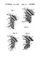
- FIGS. 1-5 and 10are vertical sectional views of various embodiments of bumpers according to the present invention, the upper section of each view showing the bumper components in their normal position and the lower section showing the bumper components in the impacted condition;
- FIGS. 6, 7, 8 and 11are sectional views showing further modifications of the present invention.
- FIG. 9is a fragmentary horizontal sectional view of another embodiment according to the present invention.
- the bumper there illustratedcomprises a fascia member 10 formed to have a generally U-shaped front portion 12 and upper and lower flanges 14 extending rearwardly from the front portion.
- a bumper bar 16extends substantially the full length of fascia 10 and is joined to flanges 14, such as by a linear weld, at 18.
- the volume between the front portion 12 of the fascia 10 and bumper bar 16comprises plastic foam.
- the foamis molded in situ by positioning the fascia 10 and the bumper bar 16 in the desired spaced relationship and introducing the foam in the volume which is bounded, in at least substantial part by the fascia and bumper bar.
- Surface area not bounded by the fascia and bumper barare bounded by core pieces of shapes selected to provide the desired configuration of the exposed foam areas.
- the core piecesare pre-treated with mold release materials.
- a foamable plasticis introduced into the volume and allowed to expand and then cure to a semi-rigid state of desired resilience and compressibility.
- the foamis preferably a resiliently flexible urethane foam which cures with an integral skin.
- the interior surfaces of the fascia 10 and the bumper bar 16may be prepared prior to the introduction of the foamable plastic to enhance bonding. Depending on the materials selected, such surface preparation may involve adhesive application, flame treatment, priming and the like.
- the foam member 20has a resiliently compressible core 22 and an integral skin 24.
- Fascia 10 and bumper bar 16are formed of materials to which the foam member 20 securely adheres when molded therein.
- the integral skin 24 on the foam core 22 and the tenacious bond between the skin 24 and the adjacent surfaces of members 10 and 16are critical features of the present invention. As pointed out above, when the bumper is mounted on the frame of a vehicle, such as by the bolts 26, and is subjected to an impact force, the localized area of the fascia where the force is applied deforms generally to the configuration shown in the lower portion of FIG. 1.
- the central portion of the foam core 22compresses an indicated at 22' and, since the bumper bar 16 is fixedly secured to flanges 14, the rounded front portion 12 of the fascia 10 is distorted into a flat vertical section 12'.
- the flattening of the front facecauses its upper and lower portions to flare outwardly in a vertical direction as indicated at 12'.
- the compression of the foam core 22will absorb a considerable portion of the impact energy, but, at the same time, the energy absorption is increased by the fact that portions of the skin 24 bonded to the fascia 10 are placed in tension.
- the stretching or elongation of the higher density integral skin 24absorbs additional impact energy and this tension tends to inhibit deformation of the fascia, thus further increasing the energy absorption.
- the tension in the skintends to return the fascia to its original contour.
- the bumper illustrated in FIG. 2differs only slightly from that illustrated in FIG. 1 in that the junction between front portion 12 and flanges 14 is formed as a V-shaped notch 28 in which the forwardly extending flanges 29 of the bumper bar are engaged to mechanically interlock fascia 10 and bumper bar 16.
- This connectionserves generally the same function as linear welds 18 in that it prevents the fascia as a whole from shifting rearwardly relative to bumper bar 16 and prevents the flanges 14 from flaring vertically when an impact force is applied to the bumper.
- the bumper barcan be formed of a non-plastic material, e.g. steel, as many plastic foams adhere well to metal.
- Foam member with the integral skin 24absorbs impact forces applied to the bumper in substantially the same manner as described above with respect to FIG. 1.
- flanges 14 of fascia 10are slidably engaged with the opposite flanged ends of bumper bar 16 so that, upon impact, the fascia as a whole can shift rearwardly relative to the bumper bar.
- the form core 22is compressed as at 22' and the upper and lower portions thereof are extruded outwardly and rearwardly as at 22'. This causes the integral skin 24 adjacent the outwardly flared portions 14' of the fascia to stretch.
- a mold release compoundis applied to the inner face of the fascia along the areas designated 30.
- FIGS. 2 and 3In the arrangements illustrated in FIGS. 2 and 3 and in the arrangements hereinafter described the fascia and the back-up member or the bumper bar are held in assembled relation solely by the bond between the integral skin on the foam core and the bumper bar. This reduces considerably the cost of manufacturing and assembling the complete bumper.
- the construction shown in FIG. 3can be employed on those vehicles where rearward displacement and vertical flaring of the flanges 14 of the fascia do not interfere with other components of the vehicle frame or body.
- the bumper bar 16is formed with openings or apertures 32 and the foam member 20 is initially molded so that an extrudate extends through the openings 32 and adheres to the inner faces of flanges 14 as indicated at 34.
- a release compoundis applied to the areas 35 at openings 32.
- the portions 36 of the foam member 20, including the integral skin thereonbecome stretched as shown in the lower portion of FIG. 4. This reduces the extent to which the flanges 14 will flare vertically and also increases the amount of energy absorbed upon impact since a portion of this energy is utilized to stretch the portion 36 and the integral skin thereon.
- the exposed areasmay be sealed with an elastomeric sealer, such as by spraying or dipping, to make the exposed areas impervious to the entry of water.
- the arrangement shown in FIG. 5is capable of withstanding a higher impact load without shearing the foam member 20.
- the fascia 38has a flat front portion 40, as distinguished from the rounded portion 12 of the fascia 10 illustrated in FIGS. 1 through 4. This difference is merely one of ornamentation and does not affect the energy absorbing properties of the bumper.
- the bumper shown in FIG. 5is merely one of ornamentation and does not affect the energy absorbing properties of the bumper.
- the bumper bar 16terminates along its upper and lower edges inwardly of the flanges 14 of the fascia and the foam member 20 is molded between the fascia and the bumper bar so that it extends rearwardly beyond the bumper bar 16 along the upper and lower edges thereof as indicated at 42.
- the vertical spacing between the bumper bar 16 and the flanges 14tends to minimize vertical displacement of the flanges on impact of the bumper.
- the arrangement shown in FIG. 6is somewhat similar to that shown in FIG. 5 except that the bumper bar 44 is formed as a hollow member extending substantially the full length of the bumper.
- Bumper bar 44can be extruded from a semi-rigid plastic or can be formed from a somewhat resilient sheet material.
- the bumper barhas the integral skin foam 46 molded therein simultaneously with the molding of the foam member 20 in the fascia.
- the integral skin foam 46may be selected to have different compressibility than the foam 20 as another means of managing the absorption and distribution of impact loads to the fascia 10.
- the portions 42 of the foam member 20which project rearwardly from the upper and lower edges of bumper bar 44 serve the same purpose as the portions 42 illustrated in FIG. 5.
- the hollow bumper barincreases the section modulus and further enhances the energy absorbing characteristics of the bumper.
- the bumper bars previously shown and describedare replaced by a thin metal tension strap 48 which extends lengthwise of the bumper at least between the two bumper mounting columns or brackets (not shown) on the vehicle frame.
- the tension strap 48is formed with a plurality of openings 50 therein and the foam member 20 is molded in situ so that the tension strap 48 is substantially completely embedded in the foam except at the area surrounding the mounting screws 26.
- the tension strap 48 and the fascia 10are held together solely by the integral skin 24 on the foam member 20.
- foam member 20extends rearwardly beyond the upper and lower edges of the tension strap 48 as at 52.
- FIG. 8the bumper bar 54 is completely embedded in the foam member 20 and the upper and lower edges which are spaced from the flanges of the fascia are inclined rearwardly as at 56.
- the vertical central portion 58 of the foam member 20is subjected to compression, but, at the portions 60 of foam member 20 adjacent the rearwardly inclined portions 56, the forces on the foam member 20 are gradually converted from compression forces to tension forces.
- these rearwardly inclined portionsavoid an abrupt change from compression to tension forces in the member 20 and further inhibit tearing of the foam at these sections.
- FIG. 8shows one of the two mounting columns or brackets 62 on the vehicle frame on which the bumper is mounted.
- FIG. 8shows the use of a separate thin metal tapping plate 64 at each of the two mounting points of the bumper bar on the vehicle frame.
- FIG. 9illustrates a special application of the bumper of the present invention wherein the bumper is adapted for mounting on a vehicle already equipped with a backing member.
- this embodimentutilizes individual metal tapping plates 64 embedded in the foam member 20 and located adjacent each of the mounting brackets for mounting the bumper on the vehicle frame.
- a metal strap 66extending between the two bumper mounting brackets on the vehicle frame functions to provide the required backup for compression of the foam 20.
- the strap 66has two spacers 68 secured thereto as by welding (as at 70).
- the bumperitself simply consists of the fascia 10, the foam member 20 and the two tapping plates 64 encapsulated in the foam as illustrated.
- FIG. 10shows another embodiment of the invention with the added feature of a rib 72 formed integrally with the bumper bar 16.
- the viewalso shows the foam 20 forwardly recessed in the area 74 proximate the vertical extreme of the bumper bar.
- the rib 72is formed as an integral extension of the bumper bar 16 to add rigidity. In its relaxed state it can be canted relative to the vertical dimension of the bumper bar to facilitate deflection upon impact of the fascia 10 as shown in FIG. 10.
- the recess in area 74provides another compression and flow pattern for the plastic foam 20 to absorb and distribute impact loads to the fascia 10.
- FIG. 11is a cross-sectional view of another bumper embodiment illustrating two additional features of the present invention.
- the section or cutting plane line of FIG. 11is offset at the vertical midpoint of the bumper to show the interruption of foam skin proximate the fastener.
- the lower flange 14 of the fascia 10is shown projecting in a generally downward direction forward of the bumper bar 16.
- the foamis made of two constituents to give it a cross-section of varying density and rigidity. That is, in the embodiment of FIG. 11, a pre-molded plastic foam bun 76 of one desired density or rigidity is embedded within a foam matrix 78 molded in situ and of another density or rigidity. This feature of varying cross-sectional density of the foam gives added control over the energy management.
- the inventionalso contemplates the same result achieved by using a homogenous plastic foam of continuously varying or graduated density across the cross-sectional area of the foam.
Landscapes
- Engineering & Computer Science (AREA)
- Mechanical Engineering (AREA)
- Vibration Dampers (AREA)
- Secondary Cells (AREA)
Abstract
Description
Claims (12)
Priority Applications (21)
| Application Number | Priority Date | Filing Date | Title |
|---|---|---|---|
| US06/624,202US4616866A (en) | 1983-12-30 | 1984-06-25 | Vehicle bumper |
| GB08430648AGB2151993B (en) | 1983-12-30 | 1984-12-05 | Vehicle bumper |
| AU36408/84AAU571911B2 (en) | 1983-12-30 | 1984-12-07 | Bumper |
| NL8403785ANL8403785A (en) | 1983-12-30 | 1984-12-13 | VEHICLE BUMPER. |
| FR848419451AFR2557523B1 (en) | 1983-12-30 | 1984-12-19 | VEHICLE BUMPER |
| DK621784ADK160197C (en) | 1983-12-30 | 1984-12-21 | BUMPER FOR TRAILERS |
| DE19843447424DE3447424A1 (en) | 1983-12-30 | 1984-12-24 | VEHICLE BUMPER |
| BE0/214248ABE901392A (en) | 1983-12-30 | 1984-12-27 | VEHICLE BUMPER. |
| ES1984291898UES291898Y (en) | 1983-12-30 | 1984-12-28 | A BUMPER FOR A VEHICLE |
| NO845259ANO159150C (en) | 1983-12-30 | 1984-12-28 | BATTERY FOR VEHICLE. |
| BR8406762ABR8406762A (en) | 1983-12-30 | 1984-12-28 | BUMPER FOR VEHICLE |
| SE8406637ASE8406637L (en) | 1983-12-30 | 1984-12-28 | bumper |
| PT79775APT79775A (en) | 1983-12-30 | 1984-12-28 | Vehicle bumper |
| IT49368/84AIT1178336B (en) | 1983-12-30 | 1984-12-28 | IMPROVEMENTS IN SHOCK ABSORBERS |
| CA000471133ACA1241981A (en) | 1983-12-30 | 1984-12-28 | Vehicle bumper |
| MX203938AMX161152A (en) | 1983-12-30 | 1985-01-02 | DEFENSE IMPROVEMENTS FOR VEHICLES |
| US06/790,942US4586739A (en) | 1984-06-25 | 1985-10-24 | Vehicle bumper |
| US06/791,501US4635984A (en) | 1984-06-25 | 1985-10-25 | Vehicle bumper |
| US06/791,588US4722563A (en) | 1984-06-25 | 1985-10-25 | Vehicle bumper |
| US06/791,436US4613177A (en) | 1984-06-25 | 1985-10-25 | Vehicle bumper |
| US06/792,113US4652031A (en) | 1984-06-25 | 1985-10-28 | Vehicle bumper |
Applications Claiming Priority (2)
| Application Number | Priority Date | Filing Date | Title |
|---|---|---|---|
| US56821583A | 1983-12-30 | 1983-12-30 | |
| US06/624,202US4616866A (en) | 1983-12-30 | 1984-06-25 | Vehicle bumper |
Related Parent Applications (1)
| Application Number | Title | Priority Date | Filing Date |
|---|---|---|---|
| US56821583AContinuation-In-Part | 1983-12-30 | 1983-12-30 |
Related Child Applications (5)
| Application Number | Title | Priority Date | Filing Date |
|---|---|---|---|
| US06/790,942DivisionUS4586739A (en) | 1984-06-25 | 1985-10-24 | Vehicle bumper |
| US06/791,501DivisionUS4635984A (en) | 1984-06-25 | 1985-10-25 | Vehicle bumper |
| US06/791,436DivisionUS4613177A (en) | 1984-06-25 | 1985-10-25 | Vehicle bumper |
| US06/791,588DivisionUS4722563A (en) | 1984-06-25 | 1985-10-25 | Vehicle bumper |
| US06/792,113DivisionUS4652031A (en) | 1984-06-25 | 1985-10-28 | Vehicle bumper |
Publications (1)
| Publication Number | Publication Date |
|---|---|
| US4616866Atrue US4616866A (en) | 1986-10-14 |
Family
ID=27074709
Family Applications (1)
| Application Number | Title | Priority Date | Filing Date |
|---|---|---|---|
| US06/624,202Expired - LifetimeUS4616866A (en) | 1983-12-30 | 1984-06-25 | Vehicle bumper |
Country Status (16)
| Country | Link |
|---|---|
| US (1) | US4616866A (en) |
| AU (1) | AU571911B2 (en) |
| BE (1) | BE901392A (en) |
| BR (1) | BR8406762A (en) |
| CA (1) | CA1241981A (en) |
| DE (1) | DE3447424A1 (en) |
| DK (1) | DK160197C (en) |
| ES (1) | ES291898Y (en) |
| FR (1) | FR2557523B1 (en) |
| GB (1) | GB2151993B (en) |
| IT (1) | IT1178336B (en) |
| MX (1) | MX161152A (en) |
| NL (1) | NL8403785A (en) |
| NO (1) | NO159150C (en) |
| PT (1) | PT79775A (en) |
| SE (1) | SE8406637L (en) |
Cited By (12)
| Publication number | Priority date | Publication date | Assignee | Title |
|---|---|---|---|---|
| US4715645A (en)* | 1986-03-12 | 1987-12-29 | Ford Motor Company | Bumper bar for a motor vehicle |
| US5269574A (en)* | 1992-02-10 | 1993-12-14 | Exxon Chemical Patents Inc. | High performance vehicle bumper |
| US5389316A (en)* | 1991-08-13 | 1995-02-14 | Woodbridge Foam Corporation | Process for producing an energy absorbing panel |
| US6209935B1 (en) | 1999-07-23 | 2001-04-03 | Daimlerchrysler Corporation | Front bumper adjustable fascia |
| US6308999B1 (en) | 1998-07-21 | 2001-10-30 | Alcoa Inc. | Multi-material hybrid bumper |
| US6416094B1 (en)* | 2001-07-27 | 2002-07-09 | Talfourd-Jones Inc. | Energy absorbing bumper |
| US20040140691A1 (en)* | 2001-10-29 | 2004-07-22 | Toshiyuki Horimatsu | Shock absorbing material |
| WO2006017288A3 (en)* | 2004-07-12 | 2007-04-12 | Tumi Inc | Umbrella having an elastomeric strap |
| USRE44893E1 (en) | 2004-03-26 | 2014-05-13 | Hanwha Azdel, Inc. | Fiber reinforced thermoplastic sheets with surface coverings |
| US9725060B1 (en) | 2015-09-03 | 2017-08-08 | Waymo Llc | Reducing surface rigidity of a vehicle |
| US11560107B2 (en) | 2020-07-28 | 2023-01-24 | Honda Motor Co., Ltd. | Impact-absorbing structure |
| US20230088716A1 (en)* | 2021-09-22 | 2023-03-23 | Stark Future, S.L. | Impact protection plate |
Families Citing this family (8)
| Publication number | Priority date | Publication date | Assignee | Title |
|---|---|---|---|---|
| GB8519432D0 (en)* | 1985-08-02 | 1985-09-11 | Ford Motor Co | Vehicle bumper |
| GB2185714B (en)* | 1986-01-25 | 1989-12-20 | Ford Motor Co | Vehicle bumper assembly with mounting bracket connecting strap |
| GB2213786B (en)* | 1987-12-23 | 1992-05-27 | Bothwell P W | Vehicle |
| DE4432082A1 (en)* | 1994-09-09 | 1996-03-14 | Bayer Ag | Safety bumper for cars, |
| GB0119357D0 (en) | 2001-08-08 | 2001-10-03 | Dow Chemical Co | Energy absorption unit |
| DE10211734A1 (en) | 2002-03-14 | 2003-10-02 | Arvinmeritor Gmbh | Composite component, in particular vehicle attachment or vehicle panel |
| DE102004041505A1 (en)* | 2004-08-27 | 2006-03-16 | Audi Ag | Deformation element for vehicle cabins comprises a covering material running from the outer side of a base to the outer sides of the side of the element |
| JP5035658B2 (en) | 2006-01-12 | 2012-09-26 | いすゞ自動車株式会社 | Vehicle under-run protector mounting structure |
Citations (5)
| Publication number | Priority date | Publication date | Assignee | Title |
|---|---|---|---|---|
| US3494607A (en)* | 1967-10-02 | 1970-02-10 | Ford Motor Co | Impact energy absorbing fluid cushion structure |
| US3856613A (en)* | 1972-08-28 | 1974-12-24 | Mccord Corp | Compressible energy absorbing article |
| US4070052A (en)* | 1976-11-15 | 1978-01-24 | Chun Wing Ng | Resilient vehicle bumper |
| US4361352A (en)* | 1979-05-21 | 1982-11-30 | Aisin Seiki Kabushiki Kaisha | Bumper for vehicles |
| US4482180A (en)* | 1981-06-30 | 1984-11-13 | Daimler-Benz Aktiengesellschaft | Bumper for motor vehicles |
Family Cites Families (18)
| Publication number | Priority date | Publication date | Assignee | Title |
|---|---|---|---|---|
| US3721433A (en)* | 1969-11-21 | 1973-03-20 | Collision Devices Inc | Deformable shock-absorbing guard |
| US3666310A (en)* | 1971-01-11 | 1972-05-30 | Gulf & Western Ind Prod Co | Shock absorbing bumper |
| DE2216324A1 (en)* | 1972-04-05 | 1973-10-25 | Gulf & Western Ind Prod Co | Vehicle bumper - slidably connected front and rear plates with interposed foam polyurethane |
| US3787083A (en)* | 1972-06-06 | 1974-01-22 | Raymond Lee Organization Inc | Safety vehicle bumper |
| US3860279A (en)* | 1973-01-15 | 1975-01-14 | Mccord Corp | Resilient energy absorbing bumper assembly |
| US3866963A (en)* | 1973-08-13 | 1975-02-18 | Mccord Corp | Energy absorbing bumper assembly |
| IT1035789B (en)* | 1974-06-21 | 1979-10-20 | Mccord Corp | URETHANE FOAM THAT ABSORBES IMPACT ENERGY IN PARTICULAR FOR BUMPERS OF VEHICLES |
| GB1545098A (en)* | 1975-12-29 | 1979-05-02 | Berol Kemi Ab | Polyurethane foams their preparation and use |
| US4106804A (en)* | 1976-02-26 | 1978-08-15 | Mccord Corporation | Energy absorbing bumper assembly |
| CA1076748A (en)* | 1976-12-02 | 1980-04-29 | Kirby E.L. Flanagan | Impact energy-absorbing urethane foam |
| US4109951A (en)* | 1977-08-18 | 1978-08-29 | Mccord Corporation | Lightweight bumper guards |
| US4328986A (en)* | 1978-04-07 | 1982-05-11 | Ex-Cell-O Corporation | Multi-media energy absorbers (flex straddle) |
| US4268079A (en)* | 1978-05-30 | 1981-05-19 | Toyota Jidosha Kogyo Kabushiki Kaisha | Shock absorbing bumper |
| US4213644A (en)* | 1978-08-17 | 1980-07-22 | Mccord Corporation | Energy-absorbing bumper assembly |
| JPS5636553U (en)* | 1979-08-29 | 1981-04-08 | ||
| JPS607248Y2 (en)* | 1979-09-26 | 1985-03-11 | トヨタ自動車株式会社 | Vehicle impact absorption bumper structure |
| JPS5766047A (en)* | 1980-10-06 | 1982-04-22 | Nissan Motor Co Ltd | Bumper with cushion |
| ES8500151A1 (en)* | 1982-10-21 | 1984-11-01 | Macchi International Spa | Shaped bodies and method for their production |
- 1984
- 1984-06-25USUS06/624,202patent/US4616866A/ennot_activeExpired - Lifetime
- 1984-12-05GBGB08430648Apatent/GB2151993B/ennot_activeExpired
- 1984-12-07AUAU36408/84Apatent/AU571911B2/ennot_activeCeased
- 1984-12-13NLNL8403785Apatent/NL8403785A/ennot_activeApplication Discontinuation
- 1984-12-19FRFR848419451Apatent/FR2557523B1/ennot_activeExpired
- 1984-12-21DKDK621784Apatent/DK160197C/ennot_activeIP Right Cessation
- 1984-12-24DEDE19843447424patent/DE3447424A1/enactiveGranted
- 1984-12-27BEBE0/214248Apatent/BE901392A/ennot_activeIP Right Cessation
- 1984-12-28ESES1984291898Upatent/ES291898Y/ennot_activeExpired
- 1984-12-28BRBR8406762Apatent/BR8406762A/ennot_activeIP Right Cessation
- 1984-12-28SESE8406637Apatent/SE8406637L/enunknown
- 1984-12-28ITIT49368/84Apatent/IT1178336B/enactive
- 1984-12-28NONO845259Apatent/NO159150C/enunknown
- 1984-12-28PTPT79775Apatent/PT79775A/enunknown
- 1984-12-28CACA000471133Apatent/CA1241981A/ennot_activeExpired
- 1985
- 1985-01-02MXMX203938Apatent/MX161152A/enunknown
Patent Citations (5)
| Publication number | Priority date | Publication date | Assignee | Title |
|---|---|---|---|---|
| US3494607A (en)* | 1967-10-02 | 1970-02-10 | Ford Motor Co | Impact energy absorbing fluid cushion structure |
| US3856613A (en)* | 1972-08-28 | 1974-12-24 | Mccord Corp | Compressible energy absorbing article |
| US4070052A (en)* | 1976-11-15 | 1978-01-24 | Chun Wing Ng | Resilient vehicle bumper |
| US4361352A (en)* | 1979-05-21 | 1982-11-30 | Aisin Seiki Kabushiki Kaisha | Bumper for vehicles |
| US4482180A (en)* | 1981-06-30 | 1984-11-13 | Daimler-Benz Aktiengesellschaft | Bumper for motor vehicles |
Cited By (13)
| Publication number | Priority date | Publication date | Assignee | Title |
|---|---|---|---|---|
| US4715645A (en)* | 1986-03-12 | 1987-12-29 | Ford Motor Company | Bumper bar for a motor vehicle |
| US5389316A (en)* | 1991-08-13 | 1995-02-14 | Woodbridge Foam Corporation | Process for producing an energy absorbing panel |
| US5269574A (en)* | 1992-02-10 | 1993-12-14 | Exxon Chemical Patents Inc. | High performance vehicle bumper |
| US6308999B1 (en) | 1998-07-21 | 2001-10-30 | Alcoa Inc. | Multi-material hybrid bumper |
| US6209935B1 (en) | 1999-07-23 | 2001-04-03 | Daimlerchrysler Corporation | Front bumper adjustable fascia |
| US6416094B1 (en)* | 2001-07-27 | 2002-07-09 | Talfourd-Jones Inc. | Energy absorbing bumper |
| US20040140691A1 (en)* | 2001-10-29 | 2004-07-22 | Toshiyuki Horimatsu | Shock absorbing material |
| USRE44893E1 (en) | 2004-03-26 | 2014-05-13 | Hanwha Azdel, Inc. | Fiber reinforced thermoplastic sheets with surface coverings |
| WO2006017288A3 (en)* | 2004-07-12 | 2007-04-12 | Tumi Inc | Umbrella having an elastomeric strap |
| US9725060B1 (en) | 2015-09-03 | 2017-08-08 | Waymo Llc | Reducing surface rigidity of a vehicle |
| US11560107B2 (en) | 2020-07-28 | 2023-01-24 | Honda Motor Co., Ltd. | Impact-absorbing structure |
| US20230088716A1 (en)* | 2021-09-22 | 2023-03-23 | Stark Future, S.L. | Impact protection plate |
| US12062804B2 (en)* | 2021-09-22 | 2024-08-13 | Stark Future, S.L. | Impact protection plate |
Also Published As
| Publication number | Publication date |
|---|---|
| GB8430648D0 (en) | 1985-01-16 |
| CA1241981A (en) | 1988-09-13 |
| BE901392A (en) | 1985-04-16 |
| AU3640884A (en) | 1985-07-04 |
| IT8449368A0 (en) | 1984-12-28 |
| FR2557523B1 (en) | 1989-12-01 |
| DE3447424A1 (en) | 1985-07-11 |
| SE8406637L (en) | 1985-07-01 |
| NO845259L (en) | 1985-07-01 |
| DK621784D0 (en) | 1984-12-21 |
| DE3447424C2 (en) | 1993-02-18 |
| NL8403785A (en) | 1985-07-16 |
| MX161152A (en) | 1990-08-08 |
| DK621784A (en) | 1985-07-01 |
| ES291898U (en) | 1987-01-01 |
| AU571911B2 (en) | 1988-04-28 |
| ES291898Y (en) | 1987-08-16 |
| DK160197C (en) | 1991-07-15 |
| SE8406637D0 (en) | 1984-12-28 |
| NO159150B (en) | 1988-08-29 |
| DK160197B (en) | 1991-02-11 |
| FR2557523A1 (en) | 1985-07-05 |
| GB2151993A (en) | 1985-07-31 |
| BR8406762A (en) | 1985-10-22 |
| GB2151993B (en) | 1988-01-27 |
| PT79775A (en) | 1985-01-01 |
| IT1178336B (en) | 1987-09-09 |
| NO159150C (en) | 1988-12-07 |
Similar Documents
| Publication | Publication Date | Title |
|---|---|---|
| US4613177A (en) | Vehicle bumper | |
| US4616866A (en) | Vehicle bumper | |
| US4722563A (en) | Vehicle bumper | |
| US4586739A (en) | Vehicle bumper | |
| CA1293985C (en) | Vehicle bumper | |
| US4652031A (en) | Vehicle bumper | |
| US5100187A (en) | Vehicle bumper | |
| US3926463A (en) | Shock absorbing buffer assembly | |
| US5114198A (en) | Synthetic resin bumper | |
| US5290078A (en) | Integral fasteners for an energy absorber of a vehicular bumper assembly | |
| US6595502B2 (en) | Bumper system for vehicles | |
| US4861097A (en) | Lightweight composite automotive door beam and method of manufacturing same | |
| US6758507B2 (en) | Energy absorbing external component for vehicle | |
| KR100384571B1 (en) | Resin shock absorber | |
| US4762352A (en) | Synthetic resin bumper assembly | |
| US20110221234A1 (en) | Noise reduction member and system | |
| JPH08119047A (en) | Impact energy absorption structure by automobile interior materials | |
| CA2655942A1 (en) | Structural reinforcement system for automotive vehicles | |
| WO1998026195A1 (en) | Impact absorber made of resin | |
| US4635984A (en) | Vehicle bumper | |
| US3979110A (en) | Energy absorbers | |
| US5711562A (en) | Bumper assembly for vehicles | |
| US4877279A (en) | Stroking fascia for vehicle energy absorbing bumper systems | |
| JPH0891160A (en) | Impact absorbing structural body for vehicle | |
| CN107848474B (en) | Beam for bumper |
Legal Events
| Date | Code | Title | Description |
|---|---|---|---|
| AS | Assignment | Owner name:LADNEY, MICHAEL, JR., GROSSE POINTE SHORES, MI Free format text:ASSIGNMENT OF ASSIGNORS INTEREST.;ASSIGNORS:LOREN, NORMAN;GORDON, WILLIAM E.;REEL/FRAME:004278/0917 Effective date:19840611 | |
| STCF | Information on status: patent grant | Free format text:PATENTED CASE | |
| AS | Assignment | Owner name:MICHIGAN NATIONAL BANK, A NATIONAL BANKING ASSOCIA Free format text:SECURITY INTEREST;ASSIGNOR:LADNEY, MICHAEL;REEL/FRAME:005012/0074 Effective date:19881123 | |
| FEPP | Fee payment procedure | Free format text:PAYOR NUMBER ASSIGNED (ORIGINAL EVENT CODE: ASPN); ENTITY STATUS OF PATENT OWNER: LARGE ENTITY | |
| FPAY | Fee payment | Year of fee payment:4 | |
| AS | Assignment | Owner name:LADNEY, MICHAEL, FLORIDA Free format text:RELEASED BY SECURED PARTY;ASSIGNOR:MICHIGAN NATIONAL BANK;REEL/FRAME:005328/0517 Effective date:19900611 | |
| AS | Assignment | Owner name:MILAD LIMITED PARTNERSHIP, FLORIDA Free format text:ASSIGNMENT OF ASSIGNORS INTEREST.;ASSIGNOR:LADNEY, MICHAEL A/K/A MICHAEL LADNEY, JR.;REEL/FRAME:005461/0503 Effective date:19900824 | |
| AS | Assignment | Owner name:MELEA LIMITED, MICHIGAN Free format text:ASSIGNMENT OF ASSIGNORS INTEREST;ASSIGNOR:MILAD LIMITED PARTNERSHIP;REEL/FRAME:006746/0267 Effective date:19931029 | |
| REMI | Maintenance fee reminder mailed | ||
| FPAY | Fee payment | Year of fee payment:8 | |
| SULP | Surcharge for late payment | ||
| FP | Lapsed due to failure to pay maintenance fee | Effective date:19941019 | |
| FEPP | Fee payment procedure | Free format text:PAT HLDR NO LONGER CLAIMS SMALL ENT STAT AS INDIV INVENTOR (ORIGINAL EVENT CODE: LSM1); ENTITY STATUS OF PATENT OWNER: LARGE ENTITY | |
| FPAY | Fee payment | Year of fee payment:12 |