US4615856A - Method for forming an individually contoured corrective seat for a wheelchair - Google Patents
Method for forming an individually contoured corrective seat for a wheelchairDownload PDFInfo
- Publication number
- US4615856A US4615856AUS06/760,245US76024585AUS4615856AUS 4615856 AUS4615856 AUS 4615856AUS 76024585 AUS76024585 AUS 76024585AUS 4615856 AUS4615856 AUS 4615856A
- Authority
- US
- United States
- Prior art keywords
- seat
- impression
- frame
- buttocks
- bags
- Prior art date
- Legal status (The legal status is an assumption and is not a legal conclusion. Google has not performed a legal analysis and makes no representation as to the accuracy of the status listed.)
- Expired - Lifetime
Links
Images


Classifications
- A—HUMAN NECESSITIES
- A61—MEDICAL OR VETERINARY SCIENCE; HYGIENE
- A61G—TRANSPORT, PERSONAL CONVEYANCES, OR ACCOMMODATION SPECIALLY ADAPTED FOR PATIENTS OR DISABLED PERSONS; OPERATING TABLES OR CHAIRS; CHAIRS FOR DENTISTRY; FUNERAL DEVICES
- A61G5/00—Chairs or personal conveyances specially adapted for patients or disabled persons, e.g. wheelchairs
- A61G5/10—Parts, details or accessories
- A61G5/1043—Cushions specially adapted for wheelchairs
- A—HUMAN NECESSITIES
- A61—MEDICAL OR VETERINARY SCIENCE; HYGIENE
- A61F—FILTERS IMPLANTABLE INTO BLOOD VESSELS; PROSTHESES; DEVICES PROVIDING PATENCY TO, OR PREVENTING COLLAPSING OF, TUBULAR STRUCTURES OF THE BODY, e.g. STENTS; ORTHOPAEDIC, NURSING OR CONTRACEPTIVE DEVICES; FOMENTATION; TREATMENT OR PROTECTION OF EYES OR EARS; BANDAGES, DRESSINGS OR ABSORBENT PADS; FIRST-AID KITS
- A61F5/00—Orthopaedic methods or devices for non-surgical treatment of bones or joints; Nursing devices ; Anti-rape devices
- A61F5/01—Orthopaedic devices, e.g. long-term immobilising or pressure directing devices for treating broken or deformed bones such as splints, casts or braces
- A—HUMAN NECESSITIES
- A61—MEDICAL OR VETERINARY SCIENCE; HYGIENE
- A61G—TRANSPORT, PERSONAL CONVEYANCES, OR ACCOMMODATION SPECIALLY ADAPTED FOR PATIENTS OR DISABLED PERSONS; OPERATING TABLES OR CHAIRS; CHAIRS FOR DENTISTRY; FUNERAL DEVICES
- A61G5/00—Chairs or personal conveyances specially adapted for patients or disabled persons, e.g. wheelchairs
- A61G5/10—Parts, details or accessories
- A61G5/1043—Cushions specially adapted for wheelchairs
- A61G5/1045—Cushions specially adapted for wheelchairs for the seat portion
- A—HUMAN NECESSITIES
- A61—MEDICAL OR VETERINARY SCIENCE; HYGIENE
- A61G—TRANSPORT, PERSONAL CONVEYANCES, OR ACCOMMODATION SPECIALLY ADAPTED FOR PATIENTS OR DISABLED PERSONS; OPERATING TABLES OR CHAIRS; CHAIRS FOR DENTISTRY; FUNERAL DEVICES
- A61G5/00—Chairs or personal conveyances specially adapted for patients or disabled persons, e.g. wheelchairs
- A61G5/10—Parts, details or accessories
- A61G5/1043—Cushions specially adapted for wheelchairs
- A61G5/1048—Cushions specially adapted for wheelchairs for the back-rest
- A—HUMAN NECESSITIES
- A61—MEDICAL OR VETERINARY SCIENCE; HYGIENE
- A61G—TRANSPORT, PERSONAL CONVEYANCES, OR ACCOMMODATION SPECIALLY ADAPTED FOR PATIENTS OR DISABLED PERSONS; OPERATING TABLES OR CHAIRS; CHAIRS FOR DENTISTRY; FUNERAL DEVICES
- A61G5/00—Chairs or personal conveyances specially adapted for patients or disabled persons, e.g. wheelchairs
- A61G5/10—Parts, details or accessories
- A61G5/1091—Cushions, seats or abduction devices
- A—HUMAN NECESSITIES
- A61—MEDICAL OR VETERINARY SCIENCE; HYGIENE
- A61G—TRANSPORT, PERSONAL CONVEYANCES, OR ACCOMMODATION SPECIALLY ADAPTED FOR PATIENTS OR DISABLED PERSONS; OPERATING TABLES OR CHAIRS; CHAIRS FOR DENTISTRY; FUNERAL DEVICES
- A61G5/00—Chairs or personal conveyances specially adapted for patients or disabled persons, e.g. wheelchairs
- A61G5/10—Parts, details or accessories
- A61G5/12—Rests specially adapted therefor, e.g. for the head or the feet
- A61G5/121—Rests specially adapted therefor, e.g. for the head or the feet for head or neck
- B—PERFORMING OPERATIONS; TRANSPORTING
- B29—WORKING OF PLASTICS; WORKING OF SUBSTANCES IN A PLASTIC STATE IN GENERAL
- B29C—SHAPING OR JOINING OF PLASTICS; SHAPING OF MATERIAL IN A PLASTIC STATE, NOT OTHERWISE PROVIDED FOR; AFTER-TREATMENT OF THE SHAPED PRODUCTS, e.g. REPAIRING
- B29C33/00—Moulds or cores; Details thereof or accessories therefor
- B29C33/38—Moulds or cores; Details thereof or accessories therefor characterised by the material or the manufacturing process
- B29C33/3842—Manufacturing moulds, e.g. shaping the mould surface by machining
- B29C33/3857—Manufacturing moulds, e.g. shaping the mould surface by machining by making impressions of one or more parts of models, e.g. shaped articles and including possible subsequent assembly of the parts
- B29C33/3878—Manufacturing moulds, e.g. shaping the mould surface by machining by making impressions of one or more parts of models, e.g. shaped articles and including possible subsequent assembly of the parts used as masters for making successive impressions
- A—HUMAN NECESSITIES
- A61—MEDICAL OR VETERINARY SCIENCE; HYGIENE
- A61G—TRANSPORT, PERSONAL CONVEYANCES, OR ACCOMMODATION SPECIALLY ADAPTED FOR PATIENTS OR DISABLED PERSONS; OPERATING TABLES OR CHAIRS; CHAIRS FOR DENTISTRY; FUNERAL DEVICES
- A61G2200/00—Information related to the kind of patient or his position
- A61G2200/10—Type of patient
- A61G2200/12—Women
- A—HUMAN NECESSITIES
- A61—MEDICAL OR VETERINARY SCIENCE; HYGIENE
- A61G—TRANSPORT, PERSONAL CONVEYANCES, OR ACCOMMODATION SPECIALLY ADAPTED FOR PATIENTS OR DISABLED PERSONS; OPERATING TABLES OR CHAIRS; CHAIRS FOR DENTISTRY; FUNERAL DEVICES
- A61G2200/00—Information related to the kind of patient or his position
- A61G2200/10—Type of patient
- A61G2200/14—Children
- A—HUMAN NECESSITIES
- A61—MEDICAL OR VETERINARY SCIENCE; HYGIENE
- A61G—TRANSPORT, PERSONAL CONVEYANCES, OR ACCOMMODATION SPECIALLY ADAPTED FOR PATIENTS OR DISABLED PERSONS; OPERATING TABLES OR CHAIRS; CHAIRS FOR DENTISTRY; FUNERAL DEVICES
- A61G2210/00—Devices for specific treatment or diagnosis
- A61G2210/10—Devices for specific treatment or diagnosis for orthopedics
- B—PERFORMING OPERATIONS; TRANSPORTING
- B29—WORKING OF PLASTICS; WORKING OF SUBSTANCES IN A PLASTIC STATE IN GENERAL
- B29C—SHAPING OR JOINING OF PLASTICS; SHAPING OF MATERIAL IN A PLASTIC STATE, NOT OTHERWISE PROVIDED FOR; AFTER-TREATMENT OF THE SHAPED PRODUCTS, e.g. REPAIRING
- B29C33/00—Moulds or cores; Details thereof or accessories therefor
- B29C33/38—Moulds or cores; Details thereof or accessories therefor characterised by the material or the manufacturing process
- B29C33/3842—Manufacturing moulds, e.g. shaping the mould surface by machining
- B29C33/3857—Manufacturing moulds, e.g. shaping the mould surface by machining by making impressions of one or more parts of models, e.g. shaped articles and including possible subsequent assembly of the parts
- B29C2033/3871—Manufacturing moulds, e.g. shaping the mould surface by machining by making impressions of one or more parts of models, e.g. shaped articles and including possible subsequent assembly of the parts the models being organic material, e.g. living or dead bodies or parts thereof
- Y—GENERAL TAGGING OF NEW TECHNOLOGICAL DEVELOPMENTS; GENERAL TAGGING OF CROSS-SECTIONAL TECHNOLOGIES SPANNING OVER SEVERAL SECTIONS OF THE IPC; TECHNICAL SUBJECTS COVERED BY FORMER USPC CROSS-REFERENCE ART COLLECTIONS [XRACs] AND DIGESTS
- Y10—TECHNICAL SUBJECTS COVERED BY FORMER USPC
- Y10S—TECHNICAL SUBJECTS COVERED BY FORMER USPC CROSS-REFERENCE ART COLLECTIONS [XRACs] AND DIGESTS
- Y10S297/00—Chairs and seats
- Y10S297/04—Wheelchair
Definitions
- This inventionrelates generally to improvements in wheelchairs, and more particularly, to improvements in correctively, custom molded wheelchair seats which are adapted for growth of individuals using the wheelchair, and for quick release mounting between the seat and wheelchair.
- beanbag type cushionshave been utilized to form contoured impressions of the human body, as shown in U.S. Pat. No. 3,830,896.
- contoured cushionshave not included changes made in the impressions formed for providing corrective positioning to the individual for whom the molded cushion is formed.
- the necessity for filling the beanbag after the individual has been positioned in the forming seatis negated by performing the shape of the backsupporting portion of the cushion while controlling the amount of negative air pressure therein.
- Multimember, modular seating systems for the handicappedhave been previously developed, as shown in U.S. Pat. No. 4,234,228.
- the cushions, disclosed thereinare not custom molded to fit the individual utilizing the seat, and the articulation provided for the chair is one of angular articulation between individual pads, rather than an expansive changeability in the chair.
- Such known articulated seating systems for wheelchairshave been very expensive, and have not provided a means for expanding the size of the seat, or the spatial relation between the buttocks-supporting portion and backsupporting portion thereof, to accomodate the rather rapid growth of children.
- the inventionis directed to a removable seat for use on a wheelchair.
- the seatincludes a seat frame having a substantially vertical backsupporting portion, and a substantially horizontal buttocks-supporting portion with cushion means mounted on the respective frame portion for providing a contoured body receiving surface.
- An inventionresides in the improvement comprising means on the backsupporting portion for vertically adjustably positioning the back portion relative to the buttocks-supporting portion, and means on the buttocks-supporting portion for horizontally adjustably positioning that portion relative to the backsupporting portion.
- the inventionis further directed to a method for forming an individually contoured corrective seat for use by a disabled person.
- the seatis of the type having a frame including a substantially vertical backsupporting portion, and a substantially horizontal buttocks-supporting portion hingedly connected thereto with each portion adapted to retain at least one resilient cushion-like member.
- the methodcomprises the steps of: positioning a human being on a seat-forming frame having back and bottom deformable bags positioned thereon with each bag including a mass of bead-like material therein in order to form impressions on the bags of the back and buttocks respectively of a human being; making corrective changes to at least one of said bags to shape the contour of same to provide for corrective positioning of the human being in the final contoured-corrective seat; evacuating air from the back and bottom bags respectively to interlock said bead-like material into a form retaining condition; forming a positive mold of the back and buttocks by applying a setable mastic material to the impressions on the bags and allowing same to set; positioning the positive to the mold in spaced relation to the back and bottom portions of the seat forming frame to define a cavity therebetween; and filling the cavity with a setable fluid material while allowing same to cure into correctively-contoured back and bottom cushions.
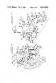
- FIG. 1is a perspective view of a contoured corrective seat assembly constructed in accordance with the present invention, as it appears mounted in a wheelchair.
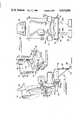
- FIG. 2is an exploded perspective view of the custom-contoured seat assembly shown in FIG. 1.
- FIG. 3is a side-elevational view of the seat assembly of the present invention shown in FIG. 1.
- FIG. 4is a front-elevational view of the seat assembly shown in FIG. 1.
- FIG. 5is a perspective view of the seat frame with the cushions removed therefrom.
- FIG. 6is an enlarged fragmentary elevational view of the lower left quick-connection coupling shown in FIG. 1 with portions cut away to show the seat retaining mechanism.
- FIG. 7is a cross-sectional view taken substantially along lines 7--7 of FIG. 6.
- FIG. 8is an enlarged fragmentary plan view of the chest support bracket shown in FIG. 2.
- FIG. 9is a cross-sectional view taken substantially along lines 9--9 of FIG. 8.
- FIG. 10is an enlarged fragmentary elevational view of the headrest mounting shown in FIG. 2.
- FIG. 11is an enlarged fragmentary plan view of the headrest mounting shown in FIG. 2.
- FIG. 12is a cross-sectional view taken substantially along line 12--12 of FIG. 10.
- FIG. 13is a fragmentary detail view of a portion of the seat frame of FIG. 5 showing frame-bracket alignment and adjustability therebetween.
- FIG. 14is a perspective view of the seat-molding frame and beanbag cushions positioned therein being preformed to accept the seating of an individual therein.
- FIG. 15is a side-elevational view of the seat-molding frame shown in FIG. 14.
- FIG. 16is a rear-elevational view of the seat-molding frame shown in FIG. 14.
- FIG. 17is a perspective view of the seat-molding frame of the invention having an individual positioned thereon with the beanbag being shaped to the contour of that individual.
- FIG. 18is a fragmentary-perspective view of the seat shown in FIG. 17 with seat-contour fixed and plaster-mold strips positioned thereover.
- FIG. 19is a perspective view of the positive-mold impression formed by the plaster gauze strips.
- FIG. 20is a perspective view of a trial-molded seat-shape formed of thermosetting plastic.
- FIG. 21is a perspective view of one of the positive molds shown in FIG. 19 with a mold-frame surrounding same.
- FIG. 22is a perspective view of the mold-frame shown in FIG. 21 with a vinal covering positioned over the mold-frame and having foam material being poured therein.
- FIG. 23is a perspective view of the finished, custom molded cushions of the present invention.
- the improved, custom-formed wheelchair seat 25, constructed in accordance with the present inventionis shown mounted on a wheelchair 26 by means of a plurality of quick-connect trunnion mounts 27--27.
- Seat 25includes a back-supporting frame 33, a buttocks-supporting frame 34, and a pair of L-shape hinge members 35, 36 which maintain the back and buttocks supporting frames in predetermined spatial relation to one another while providing for adjustable spatial and angular relation therebetween.
- the back-supporting frame 33 and buttocks-supporting frame 34are made in predetermined stock sizes and may be identical or differ in size depending on the user's needs.
- back-supporting frame 33includes a generally planar rectangular back or web centersection 37 and opposed vertical flanges 38, 40, respectively, which extend forwardly at right angles from the opposed side boundaries of the central web 37.
- Each flangeincludes thereon toward the top thereof a substantially cylindrical trunnion 29, 29, extending laterally outwardly thereof for quick releasable connection to trunnion mountings 27--27, a plurality of aligned spatially related apertures 43--43, 44--44, respectively, provide for retaining the back-supporting frame to the respective hinges 35-36, respectively, by means of links 45--45 (only one shown) having like threaded apertures 46-47 therein for retaining threaded fasteners 68--68 therein.
- Additional aligned apertures 48--48, 49--49 and 50--50, forming a generally U-shape gridare adapted to retain other members, to be discussed in greater detail below, onto the frame.
- the back-supporting frame flanges 38-40each include a distal cushion-retaining rib 38a, 40a, respectively, extending 90 degrees inwardly from the forward edge of each flange.
- the back-supporting frame 33will maintain a back-supporting cushion positioned therein, be quickly releasably retained by trunnions 28-29 to a wheelchair frame, and be adjustably mounted in a desired spatial and angular relation to through hinges 35-36, a like shaped buttocks-supporting frame member 34.
- the buttocks-supporting frame 34may be identical or substantially similar in shape to the back-supporting frame 33.
- Frame 34includes a central-rectangular, horizontally-positioned web section 52 vertical flanges 53, 54, extending from the opposed side edges thereof, and a pairs of ribs 55-56, extending inwardly from the top distal edges of flanges 53-54, respectively, for retaining a seat cushion positioned centrally therein.
- Each vertical flange 53, 54has a laterally extending trunnion 28, 28, respectively, positioned near the front end of the flange, and a plurality of apertures 59--59 and 61--61, which are adapted to retain the lower portions of hinges 35 and 36 in predetermined adjustable spatial and angular relation to the back-supporting frame 33, the mounting between hinges 35, 36, and buttocks supporting frame is accomplished by threaded fasteners and links 45, shown in connection with the back-supporting frame 33.
- the series of spaced double rows of apertures 62--62, 63--63, and 64--64, roughly in a U-shapeare utilized to mount arm rests and foot rests to the frame, as will be shown in more detail below.
- each L-shaped hinge 35, 36(with hinge 35 shown for explanation) includes a horizontally-extending base 61 and a vertically-extending arm portion 62. Adjacent the distal end of the base 65 are a pair of arcuate slots 67a-67b, adjustably retained by threaded fasteners 67--67. Adjacent the distal end of the upwardly-extending arm member 66 are a second pair of arcuate slots 68a-68b, adjustably retained by threaded fasteners 68--68. An aperture 69 on L-shape hinge 35 may be used as s seat belt mounting, as shown in FIG. 3.
- the dual pivotal mounting of back-supporting frame 33 and the buttocks-supporting frame 34 with relation to hinges 25, 26,provides heretofore unknown amounts of flexibility and adjustability to the shape of the complete seat.
- the plurality of spatially related apertures 43, 44, on back-supporting frame 33, and 59, 61 on buttocks-supporting frame 34allow movement of the vertical frame up and down and the horizontal frame inwardly and outwardly to provide a proper size and shape seat for a user, and for growth of an individual utilizing the seat.
- trunnion mounts 27each include a conventional clamp 30 having dished or oval clamping surfaces which is adapted for selectably releasable fixed mounting to a conventional wheelchair or square-tubed stroller, linking member 31 rotatably mounted to clamp 30, and a quick-release connection composed of a threaded shaft 41, extending normally from link 31 and having a recess 41a on the distal end thereof into which the end of a trunnion 28-29 may be inserted and engaged, and an internally threaded collar 42 which, when extended over the recess 41a and into engagement with the base of trunnion 28, retains the trunnion in the recess.
- a knurled or otherwise roughened outer surface on collar 42provides for hand maneuvering of same along the threads on shaft 41.
- the remainder of the seat of applicant's inventionincludes a custom-formed, back-supporting cushion, generally indicated at 70 and a custom-formed, buttocks-supporting cushion, generally indicated at 71, which removably mount in frame members 33, 34, respectively, and a plurality of peripheral items, including left and right thigh support-arm rest members 72, 73, respectively, which selectably mount onto either the buttocks-supporting frame member 34 or the back-supporting frame member 33, by means of pairs of articulated arm members 74-75, including a base 74a-75a which is adjustable affixable to either seat frame by common threaded fasteners retained through slots in the base, and a pad holding member 74b-75b which is adjustably, swingably mounted to the base in a manner similar to the swingable mounting of chest supporting member 86 discussed below.
- Each arm rest pad and pad holding membermay be selectably released to swing upwardly out of the way of a path for transferring an individual in or out of the seat, and then returned to a body supporting position.
- the upper inwardly dished surfaces 72a, 73a, respectively, of the thigh support-arm rest members 72, 73may be utilized to locate and rest the chair user's arm and elbow thereon while the sloped but substantially vertical side 72b, 73b of each respective arm support is utilized to support the thighs of the user, allowing each ingress and exit when the pads are not swung upwardly out of the way.
- the only tool required for adjustmentis a wrench, and adjustments may be made in the field at the user's situs.
- neck-head brace assembly 78including a contoured neck pad 80 thereon which is adapted to conform to the curvature of the user's neck and head-bottom.
- Pad 80is moulded around a malleable frame (not shown) which is bendable to conform to the user's neck and head shape.
- Neck brace assembly 78further includes an adjustable head-support mounting 81, which is retained on the back side of the back-supporting frame 33 by threaded fasteners 82--82 extending through mounting 81 and apertures 48--48 on frame 33 to be retained by link 83.
- An extension rod 82which is adjustably pivotally mounted at 83 to the back of pad 80 and slidably and selectively, rotatably retained on the top of mounting 81 by clamp 84.
- the double row of apertures 48--48 and 81a-81a, with the spatial distance between apertures 81a being one-half the spatial distance between apertures 48 in both directionsprovide for abundant adjustability, both vertically and laterally. As shown most clearly in FIG. 13, by switching the alignment of apertures from the left vertical column to the right vertical column on mounting 81, the mounting may be adjusted laterally in increments one-half the width of the distance between apertures 48--48.
- a chest or body supporting memberwhich is adjustably mountable on the back of frame 33, includes a curved cushion 87, which like neck support pad 80, includes a malleable frame (not shown), and an articulated mounting linkage 88-90 between the frame 33 and cushion 87.
- the L-shaped base 88 of the articulated mounting linkageincludes a distal foot 88a, including a plurality of elongate mounting slots 88b, in FIG. 2, therethrough similar to those shown in connection with articulated arm rest supports 74-75.
- Base 88is adjustably mounted to back supporting frame 33 by threaded fasteners and link 77 through apertures 49--49, 50--50 in a manner similar to the mounting of the previously noted accessory items.
- Mid-link 90is mounted at one end to L-shape arm 88 by means of pivot pin 91 for horizontal pivotal movement, and is mounted at its opposing end to cushion 87 for rotational movement therebetween around pin 93 with angular adjustment between the cushion and link being variable by means of a cam 92, which is coaxial with and sandwiched between the cushion 87 and mid-link 90.
- a spring loaded stop mechanism 91amounted on mid-link 90 adjacent one end of pin 91, selectably, releasably engages apertures in a flanged sleeve 89, concentrically mounted with pin 91, to allow pivotal movement between base 88 and mid-link 90 when desired.
- cam 92The rotation of cam 92 relative to mid-link 90 approximates 180 degrees and is limited by a pair of arcuate slots 94--94 positioned through mid-link 90 surrounding an aperture for pin 93 in spatial relation thereto. Screws 95--95 mount into the back side of cam 92, ride in slots 94--94 and may be tightened into binding relation with the side edges of the slots when fixed positioning is desired. The opposed distal ends of slots 94--94 provide stops preventing further rotation between the cam 92 and mid-link 90. Pin 93 is threaded into cushion 87 at one of a plurality of threaded apertures to provide for rotational or fixed positioning therebetween and for length adjustment, as desired.
- Loosening screws 95--95 and/or cushion 87 from pin 93allow the cushion 87 to be rotated until the fit of the cushion against the user is proper and comfortable. Then, the screws may be turned to fix the cushion 87 and cam 92 relative the mid-link 90.
- a pair of adjustable foot rests 96--96are mounted by the afore-disclosed threaded fasteners and links (not shown) fastened through apertures 64--64 adjacent the front of buttocks-supporting frame 34 so as to depend therefrom.
- Each foot rest 96includes an adjustable triangulated base 97 which is hinged at its corners and has overlapping distal ends forming the hypotenuse thereof.
- a plurality of apertures 97aare positioned all along the base for providing adjustability to the foot rest.
- a stirrup 98is mounted on the front of base 97 by conventional fasteners and, as a result of the multitude of apertures 98a on the stirrup and base, is adjustable in its vertical positioning.
- stirrup 98may be moved arcuately for user's comfort as desired.
- the corners of triangulated base 97are held together by push pins 99 to provide ease of disassembly and adjustment.
- the new and improved quickly mountable-demountable seat of the present inventionhas been shown and described as it mounts onto a wheelchair of conventional manufacture.
- the improved seat of the present inventionincludes a custom-formed, back-support cushion 60 having a generally rectangular outline sized for being press fit into the back-supporting frame 33.
- Each cushionhas an outer frontal surface 127, preferably formed of a vinyl material, which is heated and stretched into the desired shape to provide a seamless cushion cover.
- the bulk of the cushionis made of polyurethane foam which is poured into the desired shape and expands and sets to produce the custom-moulded cushions 60 and 61 in the shapes desired, as will be disclosed more fully hereafter by explanation of the preferred method of moulding means.
- a bean-bag type moulding apparatusWhen custom moulding the seat cushions 60-61, a bean-bag type moulding apparatus, generally indicated at 100, is used. It includes a back-support moulding frame 101, a buttocks-support moulding frame 102 positioned in slidable and angularly adjustable spatial relation thereto, with both being adjustably mounted on a linkage controlled mounting platform 103.
- hinge mechanisms 104, 105(only one shown), provides adjustable angular and lateral positioning of the back-support moulding frame 101 and the buttocks-support moulding frame 102.
- the back-support moulding frame 101 and buttocks-support moulding frame member 102are slightly larger than the largest of the stock size cushions made in accordance with the present invention which will fit in commercial wheelchairs. Cushions may be made smaller than the framework of the present invention by cutting the size of the mould made in the frame, as will be described in more detail below.
- a first bean-bag 106in this embodiment preferably formed of latex with polyethylene beads (not shown) therein, is mounted on the back-support moulding frame 101, and likewise, a second bean-bag 107, made of identical materials, is mounted horizontally in the buttocks-support moulding frame 102.
- a vacuum systemincludes a manifold 108 mounted on frame platform 103 and having a first vacuum line 110 in fluid communication with the interior of first bean-bag 106.
- the pressure inside first bean-bag 106is controlled by a vacuum generator (not shown) which is attached through air line 111 to manifold 108, and a first control valve 112 in line 90.
- a second vacuum line 113is connected between manifold 108 and second bean-bag 107 and includes a second control valve 114 therein.
- a partial vacuumis drawn through manifold 108 and line 90 into the back-support bean-bag 106.
- the amount of vacuum in the bag 106may be controlled by valve 112 (at about one-half inch Hg) to make the polyethylene beads in the bag 106 highly moveable when the preforming operation begins, and with a vacuum of about 3 inches Hg, the bean bag becomes hard and immobile.
- valve 114is utilized to control a partial vacuum in bean-bag 107 to rough form the bag to the approximate shape of the user, as shown in FIG. 16, cutouts 101a--101a in the web of back-support moulding frame 81 allow adjacent portions of the bean-bag to be pushed outwardly to aid in properly fitting the bag to the trunk area of the user.
- the frame 101is positioned vertically as desired, and an individual for whom custom-molded seat cushions are to be made, is seated on the bean-bags 106, 107.
- the hands of the moulder, the weight of the proposed cushion user, and control valves 112-114are all utilized to move the polyethylene beads in the latex bean-bags 86, 87, to ideally fit the shape of the user. After proper fit has been obtained, any desirable corrective shaping of the cushions is made by the moulder and the corrective shaping may be tested on the proposed user, as desired.
- control valves 112-114are adjusted to a vacuum approximating 3 inches Hg, which hardens the bean-bags 106-107 to prevent additional shape change. Thereafter, the individual for whom the cushions are to be made is lifted off of moulding frame 100 and bean-bags 106 and 107.
- plaster impregnated gauze strips 115, 116are wetted and laid on the bean-bags to make a positive mould of the desired shape of the proposed seat cushion.
- a positive mouldsuch as that shown at 117, 118, in FIG. 19, is lifted off of the bean-bags. If additional corrective changes need be made to positive moulds 117, 118, or if it appears their shape should be changed for any reason, plaster material may be added to or substracted from the positive moulds as desired, such as, by removal of or addition of materials to areas denoted in circular outline at 120 and 121 on positive moulds 117, 118.
- mould positive 117 and mould positive 118are utilized as the surfaces which the contour of the custom-made cushions will follow.
- the latex surface of bean-bags 106-107, together with the polyethylene beads thereundermay, when the bags are drawn to a high vacuum, have a bead-textured surface. This textured surface will translate directly to the positive moulds 117, 118.
- the back-side surfacemay be sanded or otherwise worked to provide a smooth surface for the cushions to be made on.
- a trial surface for the proposed custom-fitted cushionsmay be made by laying a heated sheet of thermoplastic material over the back side of mould positives 117, 118 and allowing same to cool.
- trial shape back-support member 122 and buttocks-support member 123may be formed and held together by mounting 124. If the intended user of the cushions is not located in the immediate geographic area where the cushion-making process is taking place, the trial shels 122, 123 may be shipped inexpensively to any location to determine if the proposed seat shape is proper.
- the trial seatalso has another use, as mounting cups (not shown) or other base materials may be affixed to the shell bottom and the seat may be utilized as a bathing seat for the user of the cushions.
- a mould positive 125which is similar to the mould positive 117, 118, disclosed previously, has been cut to a desired rectangular size and thereafter encircled or placed into a frame 126 having depth which is at least the desired depth of the cushion to be made.
- a sheet of vinyl material 127is heated and vacuformed inside-out over the back side of the plaster positive 125 and framing material 125 until it conforms to the desired cushion shape and outline.
- the material extending over the framemay be utilized to protect the frame from any spills or mess-making procedures.
- polyurethane foam 138is then poured into the frame 126 to a desired depth.
- the foamexpands as it sets and will rise a certain extent.
- the poured fluidseeks all of the corners and cavities of the mould during the filling process.
- the excess vinyl sheet material 107is trimmed and one of the custom-formed, seat cushions is completed and appears as shown at 60 and 61 in FIG. 23, the cushions may be press fit into the respective back-supporting frame 33 and/or buttocks-supporting frame 34 of the custom-formed seat 30 of the present invention.
- One of the advantages of the seat of the present inventionis the expansibility of the seat lengthwise to accommodate growth of the individual for whom the seat is designed, and the expansibility of the seat both lengthwise and widthwise by the relatively inexpensive replacement of one or both custom-formed cushions 60-61, and one or both seat frames if necessary, in the event the individual outgrows the first formed cushions.
- the custom moulding of second or additional cushionsis considerably less expensive than the procurement of a complete new seat should the individual outgrow the seat as originally moulded.
- the custom moulding of seat-back support and buttocks-support cushionsprovides for substantial surface contact between the individual and the seat, thus minimizing pressure sores, which have heretofore been pronounced where point or small area contact between the user and the seat has been found.
- the adjustability and custom forming of the seat assemblyplaces the users in a functional position, which is extremely important in cases of severe deformity.
- the custom-formed seat of the present inventionis affixable to various commercial wheelchairs, such as, those sold under the trade marks Everest and Jennings, and Invacare and Stainless Wheelchairs, as well as McLaren and Pogon Strollers.
Landscapes
- Health & Medical Sciences (AREA)
- Life Sciences & Earth Sciences (AREA)
- Veterinary Medicine (AREA)
- Public Health (AREA)
- General Health & Medical Sciences (AREA)
- Animal Behavior & Ethology (AREA)
- Engineering & Computer Science (AREA)
- Biomedical Technology (AREA)
- Vascular Medicine (AREA)
- Heart & Thoracic Surgery (AREA)
- Orthopedic Medicine & Surgery (AREA)
- Nursing (AREA)
- Otolaryngology (AREA)
- Manufacturing & Machinery (AREA)
- Mechanical Engineering (AREA)
- Mattresses And Other Support Structures For Chairs And Beds (AREA)
Abstract
Description
Claims (3)
Priority Applications (1)
| Application Number | Priority Date | Filing Date | Title |
|---|---|---|---|
| US90/002844AUS4615856B1 (en) | 1983-08-19 | 1985-07-29 | Method for forming an individually contoured corrective seat for a wheelchair |
Applications Claiming Priority (2)
| Application Number | Priority Date | Filing Date | Title |
|---|---|---|---|
| US52486183A | 1983-08-19 | 1983-08-19 | |
| US90/002844AUS4615856B1 (en) | 1983-08-19 | 1985-07-29 | Method for forming an individually contoured corrective seat for a wheelchair |
Related Parent Applications (1)
| Application Number | Title | Priority Date | Filing Date |
|---|---|---|---|
| US52486183ADivision | 1983-08-19 | 1983-08-19 |
Publications (2)
| Publication Number | Publication Date |
|---|---|
| US4615856Atrue US4615856A (en) | 1986-10-07 |
| US4615856B1 US4615856B1 (en) | 1993-12-29 |
Family
ID=27061625
Family Applications (1)
| Application Number | Title | Priority Date | Filing Date |
|---|---|---|---|
| US90/002844AExpired - LifetimeUS4615856B1 (en) | 1983-08-19 | 1985-07-29 | Method for forming an individually contoured corrective seat for a wheelchair |
Country Status (1)
| Country | Link |
|---|---|
| US (1) | US4615856B1 (en) |
Cited By (61)
| Publication number | Priority date | Publication date | Assignee | Title |
|---|---|---|---|---|
| GB2189183A (en)* | 1986-04-21 | 1987-10-21 | Ikeda Bussan Co | Moulding plastic articles |
| US4903690A (en)* | 1988-09-14 | 1990-02-27 | Campbell Clayton J | Spinal orthotic device and method of using same |
| US4951336A (en)* | 1989-04-03 | 1990-08-28 | Pin Dot Products | Contoured support cushions |
| US4998354A (en)* | 1990-06-20 | 1991-03-12 | Pin Dot Products | Mechanical shape sensor |
| US5052068A (en)* | 1989-11-14 | 1991-10-01 | Graebe Robert H | Contoured seat cushion |
| US5060393A (en)* | 1991-03-11 | 1991-10-29 | Pin Dot Products | Apparatus for taking body measurements |
| US5066437A (en)* | 1990-03-19 | 1991-11-19 | Barito Robert W | Method for insulating thermal devices |
| FR2665074A1 (en)* | 1990-07-26 | 1992-01-31 | Thouveny Orthopedie | Orthopaedic apparatus |
| US5193285A (en)* | 1991-08-01 | 1993-03-16 | Pin Dot Products | Mechanical shape sensor and data recorder |
| USD345072S (en) | 1992-01-07 | 1994-03-15 | E. R. Carpenter Company, Inc. | Seat cushion |
| US5294181A (en)* | 1992-01-07 | 1994-03-15 | E. R. Carpenter Company, Inc. | Seat cushion |
| US5328245A (en)* | 1992-10-30 | 1994-07-12 | Thomas J. Marks | Chair having adjustable back support |
| US5449478A (en)* | 1993-05-11 | 1995-09-12 | Gunnell, Inc. | Contoured seating construction and method |
| US5470590A (en)* | 1994-01-31 | 1995-11-28 | University Of Pittsburgh | Reusable die shape for the manufacture of molded cushions |
| FR2737433A1 (en)* | 1995-08-02 | 1997-02-07 | Maillet Orthopedie Sarl | Seat moulding procedure, esp. for orthopaedic seat for handicapped person - uses rigid shell covered by supple film layer and filled with expanding and solidifying foam |
| US5643513A (en)* | 1994-03-15 | 1997-07-01 | Searle; David H. | Method of using a form fit system for shell-type seats as used in high-performance vehicles |
| WO1998053786A3 (en)* | 1997-05-30 | 1999-03-04 | Yves Dignat | Wheelchair with improved suspension |
| WO2001043685A1 (en)* | 1999-12-15 | 2001-06-21 | Rehatechnik Möller Gmbh | Dynamic seat shell |
| EP1046385A3 (en)* | 1999-04-23 | 2001-09-19 | Vassilli s.r.l. | Chair adjustment device |
| US6358459B1 (en)* | 1998-12-29 | 2002-03-19 | Fraunhofer-Gesellschaft zur Förderung der angewandten Forschunge. V. | Method for the production of molded bodies from polymer foam particles |
| US6357829B1 (en)* | 1999-05-04 | 2002-03-19 | Colby Enterprises | Contoured body cushion |
| US6550858B1 (en)* | 2000-09-21 | 2003-04-22 | Lear Corporation | Extricable seat assembly |
| US20030121103A1 (en)* | 2000-02-04 | 2003-07-03 | Wempe Patrick L. | Method for forming a molded cushion |
| US6589467B2 (en)* | 2001-08-10 | 2003-07-08 | Michelle L. Buitenwerf | Method of forming a saddle tree mold |
| US6611980B2 (en) | 2000-02-04 | 2003-09-02 | Patrick L. Wempe | Molded cushion and method of making the same |
| US6829799B2 (en) | 2003-04-04 | 2004-12-14 | Paul J. Kuhn | Ischial tuberosity pressure relief cushion |
| US20050022306A1 (en)* | 2003-07-28 | 2005-02-03 | Hetzel Thomas R. | Reinforced and adjustable contoured seat cushion and method of reinforcing and adjusting the contoured seat cushion |
| US20050022406A1 (en)* | 2003-07-28 | 2005-02-03 | Bieganek Joseph S. | Apparatus and method for evaluating clearance from a contoured seat cushion |
| US20050022305A1 (en)* | 2003-07-28 | 2005-02-03 | Bieganek Joseph S. | Contoured seat cushion and method for offloading pressure from skeletal bone prominences and encouraging proper postural alignment |
| US20050023872A1 (en)* | 2003-07-28 | 2005-02-03 | Hetzel Thomas R. | Modular seat cushion with interlocking human support and base portions and method of creating and using a seat cushion |
| US20050067877A1 (en)* | 2001-09-10 | 2005-03-31 | Honda Access Corporation | Body support assembly |
| US20050235423A1 (en)* | 2003-07-28 | 2005-10-27 | Hetzel Thomas R | Seat cushion with adjustable contour and method of adjusting the contour of a seat cushion |
| US20050268744A1 (en)* | 2004-06-04 | 2005-12-08 | Embach James T | Conformal grasp handle |
| US20060218809A1 (en)* | 2005-03-31 | 2006-10-05 | Carl Bird | Saddle fit system and method |
| US7220376B2 (en) | 2003-07-28 | 2007-05-22 | Aspen Seating, Llc | Individually-contoured seat cushion and shape capturing and fabricating method for seat cushion |
| WO2007094569A1 (en)* | 2006-02-13 | 2007-08-23 | Eugene Medicare Co., Ltd | Customized wheelchair having back plate and seat plate formed to fit body shape and manufacturing method thereof |
| US7380886B1 (en) | 2005-03-24 | 2008-06-03 | David John Copello | Pivot column for a chair armrest or similar mechanism |
| FR2914839A1 (en)* | 2007-04-16 | 2008-10-17 | Jean Christophe Mignard | Individual's e.g. patient, entire body or part of body impression taking device, has right parallelepiped frame supporting on posts of connections connecting attachments of traction pallets, and rollers joined to frame |
| US20090124935A1 (en)* | 2007-11-12 | 2009-05-14 | Staszak Jeffrey R | Bicycle Seat Sizer And Positioning Device |
| US20090320307A1 (en)* | 2008-06-30 | 2009-12-31 | Max Mobility, Llc | Linear measurement apparatus and method |
| US20110241388A1 (en)* | 2009-09-09 | 2011-10-06 | Deborah Muller Kemp | KEMLOK Adult booster seat system |
| US8517469B1 (en) | 2012-09-06 | 2013-08-27 | Aspen Seating, Llc | Three-axis adjustable back support assembly and method |
| US20130221724A1 (en)* | 2011-02-28 | 2013-08-29 | Rebecca FOWLER | Moldable seating system |
| US8567863B2 (en) | 2011-03-02 | 2013-10-29 | Aspen Seating, Llc | Back support, orientation mechanism and method |
| US8584286B2 (en) | 2010-04-27 | 2013-11-19 | Ec Service Inc. | Systems and methods for providing a self deflating cushion |
| US20150015042A1 (en)* | 2009-01-23 | 2015-01-15 | Backjoy Orthotics, Llc | Apparatus and system for dynamically correcting posture |
| US20150298752A1 (en)* | 2014-04-21 | 2015-10-22 | Giant Manufacturing Co. Ltd | Distinguishing system for saddle contacting mode |
| CN105362004A (en)* | 2015-12-10 | 2016-03-02 | 吴绍长 | Wheelchair with cooling and heating effects for old people |
| EP1799076B1 (en)* | 2004-10-15 | 2016-11-30 | The Way to Win Limited | Seat |
| US9812100B1 (en) | 2015-03-09 | 2017-11-07 | David Mobley, LLC | Individually customized musical instrument supports, customized elements, and methods for forming the same |
| US20190210678A1 (en)* | 2017-09-18 | 2019-07-11 | Versal Manufacturing, Inc. | Moldable bicycle saddles, fitting procedures, and related technologies |
| US10421548B2 (en) | 2017-01-24 | 2019-09-24 | The Boeing Company | Configurable vehicle seat and method therefor |
| US10813461B2 (en)* | 2016-05-06 | 2020-10-27 | Equipements Sportifs Keku Inc. | Method for fabricating anatomical cushion and device to capture pressure controlled shape |
| CN112472070A (en)* | 2020-12-31 | 2021-03-12 | 宝鸡爱家家具有限责任公司 | Human body curve measuring instrument and process for customizing mattress by using measuring instrument |
| US11109687B1 (en) | 2020-02-13 | 2021-09-07 | The Boeing Company | Configurable ergonomic pad |
| US11173974B2 (en) | 2017-09-18 | 2021-11-16 | Versal Manufacturing, Inc. | Moldable bicycle saddles, external saddle heaters, fitting procedures, and related technologies |
| US20230092084A1 (en)* | 2020-09-10 | 2023-03-23 | Thuja Innovations Inc. | Thermal comfort wheelchair backrest |
| USD990180S1 (en) | 2021-04-30 | 2023-06-27 | Specialized Bicycle Components, Inc. | Bicycle saddle |
| EP4238543A1 (en) | 2022-03-04 | 2023-09-06 | Amylior Inc. | Machine-assisted method of designing and manufacturing a custom anatomical seat cushion based on anthropometric measurements |
| US11787490B2 (en) | 2019-07-22 | 2023-10-17 | Specialized Bicycle Components, Inc. | Bicycle saddle |
| US12365410B2 (en) | 2017-09-18 | 2025-07-22 | Reform Technologies Inc. | Moldable bicycle saddles, external saddle heaters, fitting procedures, and related technologies |
Citations (2)
| Publication number | Priority date | Publication date | Assignee | Title |
|---|---|---|---|---|
| US3830896A (en)* | 1972-06-08 | 1974-08-20 | Contourpedic Corp | Apparatus and process for forming contoured impressions of the human body |
| US4347213A (en)* | 1980-03-28 | 1982-08-31 | Rogers Jr John E | Method of forming contoured cushion |
- 1985
- 1985-07-29USUS90/002844Apatent/US4615856B1/ennot_activeExpired - Lifetime
Patent Citations (2)
| Publication number | Priority date | Publication date | Assignee | Title |
|---|---|---|---|---|
| US3830896A (en)* | 1972-06-08 | 1974-08-20 | Contourpedic Corp | Apparatus and process for forming contoured impressions of the human body |
| US4347213A (en)* | 1980-03-28 | 1982-08-31 | Rogers Jr John E | Method of forming contoured cushion |
Cited By (94)
| Publication number | Priority date | Publication date | Assignee | Title |
|---|---|---|---|---|
| GB2189183A (en)* | 1986-04-21 | 1987-10-21 | Ikeda Bussan Co | Moulding plastic articles |
| GB2189183B (en)* | 1986-04-21 | 1990-03-28 | Ikeda Bussan Co | Method of molding foamed plastics article |
| US4903690A (en)* | 1988-09-14 | 1990-02-27 | Campbell Clayton J | Spinal orthotic device and method of using same |
| US4951336A (en)* | 1989-04-03 | 1990-08-28 | Pin Dot Products | Contoured support cushions |
| WO1993005682A1 (en)* | 1989-11-14 | 1993-04-01 | Graebe Robert H | Contoured seat cushion |
| US5052068A (en)* | 1989-11-14 | 1991-10-01 | Graebe Robert H | Contoured seat cushion |
| US5066437A (en)* | 1990-03-19 | 1991-11-19 | Barito Robert W | Method for insulating thermal devices |
| US4998354A (en)* | 1990-06-20 | 1991-03-12 | Pin Dot Products | Mechanical shape sensor |
| FR2665074A1 (en)* | 1990-07-26 | 1992-01-31 | Thouveny Orthopedie | Orthopaedic apparatus |
| US5060393A (en)* | 1991-03-11 | 1991-10-29 | Pin Dot Products | Apparatus for taking body measurements |
| US5193285A (en)* | 1991-08-01 | 1993-03-16 | Pin Dot Products | Mechanical shape sensor and data recorder |
| USD345072S (en) | 1992-01-07 | 1994-03-15 | E. R. Carpenter Company, Inc. | Seat cushion |
| US5294181A (en)* | 1992-01-07 | 1994-03-15 | E. R. Carpenter Company, Inc. | Seat cushion |
| US5328245A (en)* | 1992-10-30 | 1994-07-12 | Thomas J. Marks | Chair having adjustable back support |
| US5449478A (en)* | 1993-05-11 | 1995-09-12 | Gunnell, Inc. | Contoured seating construction and method |
| US5470590A (en)* | 1994-01-31 | 1995-11-28 | University Of Pittsburgh | Reusable die shape for the manufacture of molded cushions |
| US5643513A (en)* | 1994-03-15 | 1997-07-01 | Searle; David H. | Method of using a form fit system for shell-type seats as used in high-performance vehicles |
| FR2737433A1 (en)* | 1995-08-02 | 1997-02-07 | Maillet Orthopedie Sarl | Seat moulding procedure, esp. for orthopaedic seat for handicapped person - uses rigid shell covered by supple film layer and filled with expanding and solidifying foam |
| WO1998053786A3 (en)* | 1997-05-30 | 1999-03-04 | Yves Dignat | Wheelchair with improved suspension |
| US6412804B1 (en) | 1997-05-30 | 2002-07-02 | M. Yves Dignat | Wheelchair with improved suspension |
| US6358459B1 (en)* | 1998-12-29 | 2002-03-19 | Fraunhofer-Gesellschaft zur Förderung der angewandten Forschunge. V. | Method for the production of molded bodies from polymer foam particles |
| EP1046385A3 (en)* | 1999-04-23 | 2001-09-19 | Vassilli s.r.l. | Chair adjustment device |
| US6357829B1 (en)* | 1999-05-04 | 2002-03-19 | Colby Enterprises | Contoured body cushion |
| WO2001043685A1 (en)* | 1999-12-15 | 2001-06-21 | Rehatechnik Möller Gmbh | Dynamic seat shell |
| US20030121103A1 (en)* | 2000-02-04 | 2003-07-03 | Wempe Patrick L. | Method for forming a molded cushion |
| US6611980B2 (en) | 2000-02-04 | 2003-09-02 | Patrick L. Wempe | Molded cushion and method of making the same |
| US6550858B1 (en)* | 2000-09-21 | 2003-04-22 | Lear Corporation | Extricable seat assembly |
| US6589467B2 (en)* | 2001-08-10 | 2003-07-08 | Michelle L. Buitenwerf | Method of forming a saddle tree mold |
| US20050067877A1 (en)* | 2001-09-10 | 2005-03-31 | Honda Access Corporation | Body support assembly |
| US7422290B2 (en)* | 2001-09-10 | 2008-09-09 | Honde Access Corporation | Body support assembly |
| US6829799B2 (en) | 2003-04-04 | 2004-12-14 | Paul J. Kuhn | Ischial tuberosity pressure relief cushion |
| US7216388B2 (en) | 2003-07-28 | 2007-05-15 | Aspen Seating, Llc | Contoured seat cushion and method for offloading pressure from skeletal bone prominences and encouraging proper postural alignment |
| US7140057B2 (en) | 2003-07-28 | 2006-11-28 | Aspen Seating, Llc | Reinforced and adjustable contoured seat cushion and method of reinforcing and adjusting the contoured seat cushion |
| US20050022406A1 (en)* | 2003-07-28 | 2005-02-03 | Bieganek Joseph S. | Apparatus and method for evaluating clearance from a contoured seat cushion |
| US20050235423A1 (en)* | 2003-07-28 | 2005-10-27 | Hetzel Thomas R | Seat cushion with adjustable contour and method of adjusting the contour of a seat cushion |
| US7373678B2 (en) | 2003-07-28 | 2008-05-20 | Aspen Seating, Llc | Seat cushion with adjustable contour and method of adjusting the contour of a seat cushion |
| US6990744B2 (en)* | 2003-07-28 | 2006-01-31 | Aspen Seating, Llc | Apparatus and method for evaluating clearance from a contoured seat cushion |
| US20050023872A1 (en)* | 2003-07-28 | 2005-02-03 | Hetzel Thomas R. | Modular seat cushion with interlocking human support and base portions and method of creating and using a seat cushion |
| US7220376B2 (en) | 2003-07-28 | 2007-05-22 | Aspen Seating, Llc | Individually-contoured seat cushion and shape capturing and fabricating method for seat cushion |
| US7395566B2 (en)* | 2003-07-28 | 2008-07-08 | Aspen Seating, Llc | Method of reinforcing and adjusting a contoured seat cushion |
| US20050022305A1 (en)* | 2003-07-28 | 2005-02-03 | Bieganek Joseph S. | Contoured seat cushion and method for offloading pressure from skeletal bone prominences and encouraging proper postural alignment |
| US20070028385A1 (en)* | 2003-07-28 | 2007-02-08 | Hetzel Thomas R | Reinforced and adjustable contoured seat cushion and method of reinforcing and adjusting the contoured seat cushion |
| US20050022306A1 (en)* | 2003-07-28 | 2005-02-03 | Hetzel Thomas R. | Reinforced and adjustable contoured seat cushion and method of reinforcing and adjusting the contoured seat cushion |
| US7895917B2 (en) | 2004-06-04 | 2011-03-01 | Gm Global Technology Operations, Inc. | Conformal grasp handle |
| US20050268744A1 (en)* | 2004-06-04 | 2005-12-08 | Embach James T | Conformal grasp handle |
| EP1799076B1 (en)* | 2004-10-15 | 2016-11-30 | The Way to Win Limited | Seat |
| US7380886B1 (en) | 2005-03-24 | 2008-06-03 | David John Copello | Pivot column for a chair armrest or similar mechanism |
| US20070273185A1 (en)* | 2005-03-31 | 2007-11-29 | Specialized Bicycle Components, Inc. | Saddle fit system and method |
| US20080134533A1 (en)* | 2005-03-31 | 2008-06-12 | Specialized Bicycle Components, Inc. | Saddle fit system and method |
| US7284336B2 (en) | 2005-03-31 | 2007-10-23 | Specialized Bicycle Components, Inc. | Saddle fit system and method |
| US7441343B2 (en) | 2005-03-31 | 2008-10-28 | Specialized Bicycle Components, Inc. | Saddle fit system and method |
| US7448141B2 (en) | 2005-03-31 | 2008-11-11 | Specialized Bicycle Components, Inc. | Saddle fit system and method |
| US20060218809A1 (en)* | 2005-03-31 | 2006-10-05 | Carl Bird | Saddle fit system and method |
| JP2007215998A (en)* | 2006-02-13 | 2007-08-30 | Eugene Medicare Co Ltd | Manufacturing method of customized wheelchair and customized wheelchair |
| WO2007094569A1 (en)* | 2006-02-13 | 2007-08-23 | Eugene Medicare Co., Ltd | Customized wheelchair having back plate and seat plate formed to fit body shape and manufacturing method thereof |
| FR2914839A1 (en)* | 2007-04-16 | 2008-10-17 | Jean Christophe Mignard | Individual's e.g. patient, entire body or part of body impression taking device, has right parallelepiped frame supporting on posts of connections connecting attachments of traction pallets, and rollers joined to frame |
| US20090124935A1 (en)* | 2007-11-12 | 2009-05-14 | Staszak Jeffrey R | Bicycle Seat Sizer And Positioning Device |
| US9314187B2 (en) | 2007-11-12 | 2016-04-19 | Trek Bicycle Corporation | Bicycle seat sizer and positioning device |
| US20090320307A1 (en)* | 2008-06-30 | 2009-12-31 | Max Mobility, Llc | Linear measurement apparatus and method |
| US7841098B2 (en)* | 2008-06-30 | 2010-11-30 | Max Mobility, Llc | Linear measurement apparatus and method |
| US10849428B2 (en) | 2009-01-23 | 2020-12-01 | Backjoy Orthotics, Llc | Apparatus and system for dynamically correcting posture |
| US10034548B2 (en)* | 2009-01-23 | 2018-07-31 | Backjoy Orthotics, Llc | Apparatus and system for dynamically correcting posture |
| US20150015042A1 (en)* | 2009-01-23 | 2015-01-15 | Backjoy Orthotics, Llc | Apparatus and system for dynamically correcting posture |
| US20110241388A1 (en)* | 2009-09-09 | 2011-10-06 | Deborah Muller Kemp | KEMLOK Adult booster seat system |
| US8220873B2 (en)* | 2009-09-09 | 2012-07-17 | Deborah Muller Kemp | KEMLOK adult Booster Seat System |
| US8584286B2 (en) | 2010-04-27 | 2013-11-19 | Ec Service Inc. | Systems and methods for providing a self deflating cushion |
| US9186290B2 (en)* | 2011-02-28 | 2015-11-17 | The Comfort Companies, Inc. | Moldable seating system |
| US20130221724A1 (en)* | 2011-02-28 | 2013-08-29 | Rebecca FOWLER | Moldable seating system |
| US8567863B2 (en) | 2011-03-02 | 2013-10-29 | Aspen Seating, Llc | Back support, orientation mechanism and method |
| US8517469B1 (en) | 2012-09-06 | 2013-08-27 | Aspen Seating, Llc | Three-axis adjustable back support assembly and method |
| US10414454B2 (en)* | 2014-04-21 | 2019-09-17 | Giant Manufacturing Co., Ltd. | Distinguishing system for saddle contacting mode |
| US20150298752A1 (en)* | 2014-04-21 | 2015-10-22 | Giant Manufacturing Co. Ltd | Distinguishing system for saddle contacting mode |
| US9812100B1 (en) | 2015-03-09 | 2017-11-07 | David Mobley, LLC | Individually customized musical instrument supports, customized elements, and methods for forming the same |
| US10283095B1 (en) | 2015-03-09 | 2019-05-07 | David Mobley, LLC | Individually customized musical instrument supports, customized elements and methods for forming the same |
| CN105362004A (en)* | 2015-12-10 | 2016-03-02 | 吴绍长 | Wheelchair with cooling and heating effects for old people |
| US10813461B2 (en)* | 2016-05-06 | 2020-10-27 | Equipements Sportifs Keku Inc. | Method for fabricating anatomical cushion and device to capture pressure controlled shape |
| US11053009B2 (en) | 2017-01-24 | 2021-07-06 | The Boeing Company | Configurable vehicle seat and method therefor |
| US10481588B2 (en)* | 2017-01-24 | 2019-11-19 | The Boeing Company | Configurable vehicle seat and method therefor |
| US11827364B2 (en) | 2017-01-24 | 2023-11-28 | The Boeing Company | Configurable vehicle seat and method therefor |
| US20210253256A1 (en) | 2017-01-24 | 2021-08-19 | The Boeing Company | Configurable vehicle seat and method therefor |
| US10421548B2 (en) | 2017-01-24 | 2019-09-24 | The Boeing Company | Configurable vehicle seat and method therefor |
| US20190210678A1 (en)* | 2017-09-18 | 2019-07-11 | Versal Manufacturing, Inc. | Moldable bicycle saddles, fitting procedures, and related technologies |
| US11173974B2 (en) | 2017-09-18 | 2021-11-16 | Versal Manufacturing, Inc. | Moldable bicycle saddles, external saddle heaters, fitting procedures, and related technologies |
| US11654992B2 (en) | 2017-09-18 | 2023-05-23 | Reform Technologies Inc. | Moldable bicycle saddles, external saddle heaters, fitting procedures, and related technologies |
| US12365410B2 (en) | 2017-09-18 | 2025-07-22 | Reform Technologies Inc. | Moldable bicycle saddles, external saddle heaters, fitting procedures, and related technologies |
| US10399626B2 (en)* | 2017-09-18 | 2019-09-03 | Versal Manufacturing, Inc. | Moldable bicycle saddles, fitting procedures, and related technologies |
| US12084140B2 (en) | 2019-07-22 | 2024-09-10 | Specialized Bicycle Components, Inc. | Bicycle saddle |
| US11787490B2 (en) | 2019-07-22 | 2023-10-17 | Specialized Bicycle Components, Inc. | Bicycle saddle |
| US11109687B1 (en) | 2020-02-13 | 2021-09-07 | The Boeing Company | Configurable ergonomic pad |
| US20230092084A1 (en)* | 2020-09-10 | 2023-03-23 | Thuja Innovations Inc. | Thermal comfort wheelchair backrest |
| US12161591B2 (en)* | 2020-09-10 | 2024-12-10 | Thuja Innovations Inc. | Thermal comfort wheelchair backrest |
| CN112472070A (en)* | 2020-12-31 | 2021-03-12 | 宝鸡爱家家具有限责任公司 | Human body curve measuring instrument and process for customizing mattress by using measuring instrument |
| USD990180S1 (en) | 2021-04-30 | 2023-06-27 | Specialized Bicycle Components, Inc. | Bicycle saddle |
| EP4238543A1 (en) | 2022-03-04 | 2023-09-06 | Amylior Inc. | Machine-assisted method of designing and manufacturing a custom anatomical seat cushion based on anthropometric measurements |
Also Published As
| Publication number | Publication date |
|---|---|
| US4615856B1 (en) | 1993-12-29 |
Similar Documents
| Publication | Publication Date | Title |
|---|---|---|
| US4615856A (en) | Method for forming an individually contoured corrective seat for a wheelchair | |
| US4763951A (en) | Threaded locking coupler | |
| US5551756A (en) | Orthotic wheelchair positioning device and support system | |
| US4993164A (en) | Measuring device | |
| CA1310574C (en) | Vehicle seat with adjustable thigh support | |
| US5690389A (en) | Pneumatic, ball-shaped chair | |
| US4753482A (en) | Customized modular seating system | |
| EP0268746B1 (en) | Shell chair and tilt mechanism | |
| US5660438A (en) | Chair having ergonomic lumbar support cushion | |
| CA1098436A (en) | Obstetric chair | |
| US5452940A (en) | Pressure relief back cushion | |
| US5228747A (en) | Seating system | |
| US5593211A (en) | Deformity back system | |
| US4007962A (en) | Chair with adjustable back | |
| GB1591024A (en) | Support device | |
| WO2003009725A3 (en) | Adjustable seat for watercraft | |
| US20010040402A1 (en) | Adjustable split seat | |
| WO1996012465A1 (en) | Orthotic seat | |
| US5523040A (en) | Method and apparatus for making a custom support | |
| US4852945A (en) | Comprehensive contour chair apparatus | |
| KR101339991B1 (en) | Method of making customized seat | |
| US3843197A (en) | Football helmet stool | |
| CA1230814A (en) | Contoured corrective seats for wheelchair | |
| US6033025A (en) | Notched support pads for cushioning wheelchair seatback | |
| CN205321827U (en) | A kind of back seat with linkage armrest |
Legal Events
| Date | Code | Title | Description |
|---|---|---|---|
| STCF | Information on status: patent grant | Free format text:PATENTED CASE | |
| CC | Certificate of correction | ||
| FPAY | Fee payment | Year of fee payment:4 | |
| RR | Request for reexamination filed | Effective date:19920928 | |
| AS | Assignment | Owner name:PIN DOT PRODUCTS, ILLINOIS Free format text:ASSIGNMENT OF ASSIGNORS INTEREST.;ASSIGNOR:SILVERMAN, MICHAEL W.;REEL/FRAME:006335/0721 Effective date:19921130 | |
| FEPP | Fee payment procedure | Free format text:PAYOR NUMBER ASSIGNED (ORIGINAL EVENT CODE: ASPN); ENTITY STATUS OF PATENT OWNER: LARGE ENTITY | |
| B1 | Reexamination certificate first reexamination | ||
| FPAY | Fee payment | Year of fee payment:8 | |
| AS | Assignment | Owner name:INVACARE CORPORATION, OHIO Free format text:ASSIGNMENT OF ASSIGNORS INTEREST;ASSIGNOR:PIN DOT PRODUCTS;REEL/FRAME:007674/0474 Effective date:19950505 | |
| FEPP | Fee payment procedure | Free format text:PAYER NUMBER DE-ASSIGNED (ORIGINAL EVENT CODE: RMPN); ENTITY STATUS OF PATENT OWNER: LARGE ENTITY Free format text:PAYOR NUMBER ASSIGNED (ORIGINAL EVENT CODE: ASPN); ENTITY STATUS OF PATENT OWNER: LARGE ENTITY | |
| FEPP | Fee payment procedure | Free format text:PAT HLDR NO LONGER CLAIMS SMALL ENT STAT AS SMALL BUSINESS (ORIGINAL EVENT CODE: LSM2); ENTITY STATUS OF PATENT OWNER: LARGE ENTITY | |
| FPAY | Fee payment | Year of fee payment:12 | |
| AS | Assignment | Owner name:INVACARE CORPORATION, OHIO Free format text:ASSIGNMENT OF ASSIGNORS INTEREST;ASSIGNOR:SILVERMAN, MICHAEL W.;REEL/FRAME:009624/0584 Effective date:19980810 |