US4614868A - Fiber optic seam tracking apparatus - Google Patents
Fiber optic seam tracking apparatusDownload PDFInfo
- Publication number
- US4614868A US4614868AUS06/660,354US66035484AUS4614868AUS 4614868 AUS4614868 AUS 4614868AUS 66035484 AUS66035484 AUS 66035484AUS 4614868 AUS4614868 AUS 4614868A
- Authority
- US
- United States
- Prior art keywords
- light
- fiber optic
- optic bundle
- galvanometer
- shaft
- Prior art date
- Legal status (The legal status is an assumption and is not a legal conclusion. Google has not performed a legal analysis and makes no representation as to the accuracy of the status listed.)
- Expired - Lifetime
Links
Images


Classifications
- B—PERFORMING OPERATIONS; TRANSPORTING
- B23—MACHINE TOOLS; METAL-WORKING NOT OTHERWISE PROVIDED FOR
- B23K—SOLDERING OR UNSOLDERING; WELDING; CLADDING OR PLATING BY SOLDERING OR WELDING; CUTTING BY APPLYING HEAT LOCALLY, e.g. FLAME CUTTING; WORKING BY LASER BEAM
- B23K9/00—Arc welding or cutting
- B23K9/12—Automatic feeding or moving of electrodes or work for spot or seam welding or cutting
- B23K9/127—Means for tracking lines during arc welding or cutting
- B23K9/1272—Geometry oriented, e.g. beam optical trading
- B23K9/1274—Using non-contact, optical means, e.g. laser means
- B—PERFORMING OPERATIONS; TRANSPORTING
- B23—MACHINE TOOLS; METAL-WORKING NOT OTHERWISE PROVIDED FOR
- B23Q—DETAILS, COMPONENTS, OR ACCESSORIES FOR MACHINE TOOLS, e.g. ARRANGEMENTS FOR COPYING OR CONTROLLING; MACHINE TOOLS IN GENERAL CHARACTERISED BY THE CONSTRUCTION OF PARTICULAR DETAILS OR COMPONENTS; COMBINATIONS OR ASSOCIATIONS OF METAL-WORKING MACHINES, NOT DIRECTED TO A PARTICULAR RESULT
- B23Q35/00—Control systems or devices for copying directly from a pattern or a master model; Devices for use in copying manually
- B23Q35/04—Control systems or devices for copying directly from a pattern or a master model; Devices for use in copying manually using a feeler or the like travelling along the outline of the pattern, model or drawing; Feelers, patterns, or models therefor
- B23Q35/08—Means for transforming movement of the feeler or the like into feed movement of tool or work
- B23Q35/12—Means for transforming movement of the feeler or the like into feed movement of tool or work involving electrical means
- B23Q35/127—Means for transforming movement of the feeler or the like into feed movement of tool or work involving electrical means using non-mechanical sensing
- B23Q35/128—Sensing by using optical means
Definitions
- This inventionrelates generally to an apparatus for detecting anomales on a workpiece surface, and more particularly, to a sensor for detecting weld groove depth, shape, and location.
- the present inventionis directed to incorporating the advantages and overcoming the problems as set forth above.
- an apparatusis movable in a first direction along a plane "P" for optically detecting anomalies on a surface of a workpiece.
- the apparatusincludes first and second fiber optic bundles, each having first and second ends, and a projected source of light.
- a first meansreceives the projected light and alters the path of the light wherein the light is scanned across the first end of the first fiber optic bundle.
- a second meansimages the light onto substantially a single fiber of the first fiber optic bundle.
- a third meansreceives the light from the second end of the first fiber optic bundle, images the light relative to the workpiece surface, and establishes a spot of light.
- a fourth meansreceives reflected light from the spot and images the light onto the second end of the second fiber optic bundle.
- a fifth meansreceives light from the first end of the second fiber optic bundle and images the light.
- a sixth meansreceives the light from the fifth means and delivers an electrical signal in response to the position of the light.
- Known vision guidance systemsare large, bulky devices which inhibit the mobility of, for example, welding equipment when affixed to the welding head. These guidance systems must necessarily be located in close proximity to the weld groove to insure that the reflected signal may be differentiated from the optical "noise" typically associated with a manufacturing environment and most notably emanating from the welding flash.
- the present apparatusis directed toward maintaining an acceptable energy density, such that removing the guidance system from the immediate area of the weld groove will not adversely affect the signal to noise ratio.
- FIG. 1is a schematic diagram showing the relative positioning of the components of the present apparatus
- FIG. 2is a schematic diagram illustrating the optical system of the present apparatus
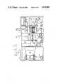
- FIG. 3is a cross-sectional view of the present apparatus
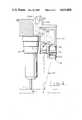
- FIG. 4is a cross-sectional view of the sensor attached directly to the welding head.
- FIG. 5is an end view of a fiber optic bundle.
- FIG. 1illustrates an apparatus 10 movable in a first direction along a plane "P" for optically detecting anomales on the surface of a workpiece 11.
- FIG. 1illustrates the apparatus 10 in approximate relationship to the welding head 13 and workpiece surface 11.
- FIG. 2illustrates the optics of the apparatus 10 in greater detail, and a better appreciation of the instant invention may be had by referring to both FIGS. 1 and 2 in the following discussion.
- the apparatus 10includes first and second fiber optic bundles 12,14, each having first and second ends 16,18;20,22.
- a source of light 24consists, for example, of a laser diode 26 and output optics projecting a 10 mm diameter of monochromatic light having a wavelength of 830 nanometers, a helium-neon (He-Ne) laser 28 projecting a 0.8 mm beam of monochromatic light having a wavelength of 628 nanometers, a first mirror 30 for orthogonally reflecting the He-Ne laser light, and a dichroic mirror 32 for passing the He-Ne laser light and orthogonally reflecting the laser diode light.
- He-Nehelium-neon
- a first means 34receives the projected light and alters the path of the light by linearly scanning the light across the first end 16 of the first fiber optic bundle 12.
- the first means 34includes a galvanometer 36 positioned intermediate the source of light 24 and the first end 16 of the first fiber optic bundle 12.
- the galvanometerhas a shaft 37 angularly positionable relative to the first end 16 of the first fiber optic bundle 12 for varying the angle of incidence of the two collimated light sources 26,28 with a first mirror 38 fixedly attached to the galvanometer shaft.
- the galvanometer 36oscillates the mirror 38 through an angle of 2° under control of a remote processor 39 by varying the amount of current delivered to the galvanometer 36. Varying the angle of incidence causes the light to be reflected in a plane intersecting a second means 40 which focuses the light onto substantially a single fiber of the first fiber optic bundle 12.
- the second means 40includes a spherical lens 42 which has, for example, a 25 mm focal length and is positioned 25 mm from the fiber optic bundle 12.
- the combination of the 25 mm lens and the 830 nm lightwill image the 10 mm diameter laser light down to a diameter of approximately 4 microns, resulting in approximately 95% of the available power being delivered to a single 10 micron fiber. Further, in the event that a laser having a wavelength other than 830 nm is selected, an appropriate adjustment in the positioning and the focal length of the lens 42 will be required to obtain an image of similar dimensions.
- Laser lightis known to have a Gaussian distribution; thus, even a spot which has a 15 micron diameter coaxially imaged onto a 10 micron fiber transmits 70% of the available power through a single fiber. It has been discovered that a substantial portion of the light may be transmitted through a single fiber of the fiber optic bundle 12 by limiting the size of the spot imaged onto the fiber optic bundle. This is important to maintain the energy density of the transmitted light at a sufficiently high level to insure that the light reflected from the workpiece surface 11 is of adequate intensity to be differentiated from the "noise" generated by the arc flash of the welder. That is to say, a high energy density of the laser light is a key ingredient in sustaining a high signal to noise ratio.
- an end view of the fiber optic bundle 12is illustrated and shows the individual fibers arranged in an orthogonal matrix.
- Laser light imaged onto the bundle 12is indicated by the broken line 43 and has a diameter of approximately 30 microns.
- the imageis shown to fall wholly on four fibers and partially onto eight separate fibers. These partially illuminated fibers will not maintain this partial illumination, but will allow the light to diverge and homogeneously illuminate the entire fiber.
- the light projected from the second end 18 of the fiber optic bundlewill be significantly larger than the 30 micron input diameter. Additionally, the light lost in the spaces between the individual fibers becomes more significant as the diameter increases.
- the present apparatus 10will image laser light into a 4 micron spot illustrated by broken line 44.
- a third means 45receives the light from the second end 18 of the first fiber optic bundle 12, images the light relative to a workpiece surface 11, and establishes a spot of light.
- the third means 45includes, for example, a spherical lens 46 positioned adjacent the second end 18 of the first fiber optic bundle 12 and a wedge prism 48 which has first and second surfaces 50,52 defined by first and second intersecting planes 54,56.
- the prism 48is positioned adjacent the spherical lens 46 with the intersection of the planes 54,56 forming a line 58 substantially perpendicular to the plane "P".
- the wedge prism 48is positioned to refract the light at a predetermined angle in a direction toward the welding head 13, positioning the line scan as close as possible to the welding head 13. Similar results could be achieved by positioning the fiber optic cable 12 and the spherical lens 46 at this same predetermined angle and projecting the light toward the workpiece surface without the aid of the wedge prism 48. However, the angular positioning would require that the lens 46 and cable 12 be moved further from the welding head 13, enlarging the packaging requirements of the means 45, and reducing mobility of the welding head 13. Further, a window 60 is positioned intermediate the workpiece surface 11 and the prism 48.
- the window 60is provided to protect the optical surface of the prism 48 from weld splatter and is constructed from sapphire to take advantage of its extreme hardness. This hardness not only discourages the weld splatter from sticking to the window 60, but also, environmental conditions will ultimately result in the window 60 becoming occluded by the collection of particulates carried in the smoke generated by the welding process. Cleaning of the window 60 is, therefor, necessary on a regular basis, and absent the protective window hardness, much care would be required to avoid scratching the window 60. Over a period of time the optical transmissability of the window 60 would deteriorate to such a point that sufficient laser light would be unable to pass through the window 60 and establish a spot of light. Construction of the protective window 60 from sapphire allows the use of readily available cleaning agents (e.g., paper products) without affecting clarity.
- readily available cleaning agentse.g., paper products
- the spot of light established on the workpiece surface 11is reflected in all directions forming a hemisphere of light due to a highly variable coefficient of reflection. A portion of this reflected light is directed to and received by a fourth means 62 where it is imaged onto substantially a single fiber at the second end 22 of the second fiber optic bundle 14.
- the fourth means 62includes, for example, a protective window 64, similar to the window 60, and a spherical lens 66.
- the spherical lens 66is the counterpart to the spherical lens 46, one having the inverse imaging properties of the other and each being positioned the same distance from the ends 18,22 of their respective fiber optic bundles 12,14.
- inverse imaging propertiesare employed to insure that, irrespective of the workpiece surface 11 being within the focal plane of the lens 46, the spot of light imaged onto the workpiece surface 11 will be imaged by the lens 66 into a diameter substantially equal to the internal diameter of a single fiber. For example, if the lens 46 is chosen to provide magnification of 20, then the lens 66 would provide magnification of 1/20. A spot of light formed on the workpiece surface 11 will have a diameter determined by its distance from the focal plane.
- the lens 66counteracts the growth of the projected light and acts to return the diameter to the original diameter as received by the lens 46.
- This diameteris ideally the diameter of a single fiber, but aberrations in the lens prevent the diameter from being returned to its exact original dimensions and some blurring of the image will occur.
- the reflected lightis transmitted through the second fiber optic bundle 14 where a fifth means 68 receives the light from the first end 20 of the second fiber optic bundle 14 and images the light onto a sixth means 70 which delivers an electrical signal to the remote processor 39 in response to the position of the light.
- the fifth means 68includes, for example, a collimating lens 72 positioned adjacent the first end 20 of the second fiber optic bundle 14.
- a seventh means 74receives light from the fifth means 68, scans the light in synchronization with the first means 34, and delivers the light to the sixth means 70.
- the seventh means 74includes, for example, a second galvanometer 76 positioned intermediate the fifth and sixth means 68,70.
- the galvanometer 76has a shaft 78 angularly positionable relative to the first end 20 of the second fiber optic bundle 14 in synchronization with the shaft 37 of the first galvanometer 36.
- a second mirror 80is fixedly attached to and rotatable in unison with the shaft 78 through an angle of 8°, thereby reflecting the collimated light in a plane intersecting the sixth means 70.
- the 8° angular displacement of the mirror 80compensates for the sharper swing induced by the collimating lens 72.
- the receive opticsdiffer from the transmit optics in that the amount of light received is only a small portion of the amount of light transmitted; consequently, optical losses which could be considered inconsequential in the transmit optics become much more significant in the receive optics.
- the collimating lens 72is selected to have a relatively short focal length and a low F number allowing as much light as possible to be conveyed.
- short focal lengths and low F numbersincrease the angular displacement of the collimated light delivered through the collimating lens 72.
- light which is transmitted through the 2° arcis received in an 8° arc.
- Both the galvanometers 36,76are under direct control of the remote processor 39, making the adaptation of the second galvanometer 76 to traverse the 8° arc in synchronization with the 2° arc of the first galvanometer 36 a matter of software control.
- a mirror 82receives the light reflected by the galvanometer mirror 80 and orthogonally reflects the light through a bandpass filter 84 which has a 2 nm wide pass band.
- the filter 84acts to pass only the 830 nm laser light and prevents any false signals from being generated by the "noise" of welding arc flash or any incidental light.
- the width of the bandpass filter pass bandis selected to correspond to the wavelength of the projected laser diode light.
- a change in the wavelength of the laser diode 26must necessarily be associated with an appropriate change in the bandpass filter 84.
- a spherical lens 86has, for example, a focal length of 50 mm and acts to image the filtered light on a silicon photo-diode line array 88.
- the diode line array 88converts the imaged light into a digital signal representing which of the diodes in the array 88 is receiving the filtered light.
- the oscillating mirror 80could be replaced by a stationary mirror and a matrix diode array could be substituted for the line diode array 88. This system would, rather than descan the signal, allow movement in both the x and y coordinates which the remote processor 39 would interpret to extract topographical information about the workpiece surface 11.
- FIG. 3illustrates a portion of the apparatus 10, hereinafter referred to as the optical processor 90.
- the optical processor 90is located on the welding robot, but remotely located from the welding torch.
- Variable current signalsare delivered to the galvonometers 36,76 by the remote processor 39, which is preferably separate from the optical processor 90 and remote from the welding robot.
- the processor 39contains within its memory a software routine for assimilating the digital signals provided by the line diode array 88, determining the weld groove width, depth, and location within the field of view.
- the processor 39will, subsequently, provide control signals to the welding robot to control direction and speed of movement, wire feed rate, welding voltage, etc.
- the software control routinesare not considered part of the present invention and, therefor, have not been disclosed in the instant application.
- the welding robotis not considered to be part of the present invention and may take the form of any commercially available industrial robot.
- the optical processor 90is housed within a sealable container 91 for protecting the optics from the collection of airborne particulates abundantly present in manufacturing type environments.
- the HeNe laser 28is fixedly attached to the container 91 along with a respective power supply 92. Collimated light from the HeNe laser 28 is reflected by the mirror 30 and passed through the dichroic mirror 32.
- the HeNe laseris not intended to affect the intensity of the light reflected from the workpiece surface 11, but is expected to provide a visible indication of the position of the invisible laser diode light.
- the laser diode 26emits monochromatic light of 830 nm which is invisible to the naked eye.
- the laser diode 26receives power from a power supply 94 and delivers light through the collimating lens 33 which is reflected by the dichroic mirror 32.
- the dichroic mirror 32coaxially positions the HeNe and laser diode light such that any adjustments made to the apparatus 10 which affect the visible HeNe light must necessarily similarly affect the invisible laser diode light.
- the light from the dichroic mirror 32is reflected by the scanning mirror 38 and imaged by the spherical lens 42 onto the fiber optic bundle 12.
- a jacking stage 100is positioned about the spherical lens 42 and allows for fine focusing of the transmitted laser light by moving the lens 42 relative to the first end 16 of the first fiber optic bundle 12.
- a rotary stage 96allows the fiber optic bundle 12 to be rotationally positioned, aligning the center points of a row of fibers with the line segment formed by the scanned light.
- the combined adjustability of the rotary and jacking stages (100,96)enables the scanned light to be transmitted along a single row of fibers, serially linking each individual fiber with the projected laser light. The adjustment process would be extremely difficult if the operator were unable to see the imaged laser light; however, commercially available infrared focused viewers will be used during the adjustment process making the 830 nm light visible.
- the reception portion of the optical processor 90also includes a rotary and jacking stage 98,102 to insure that the reflected light is generally swept in a plane perpendicular to the axis of rotation of the descanning mirror 80 and to allow for fine focusing of the received light.
- the collimating lens 72receives the reflected laser light after it has been properly oriented by the rotary and jacking stages 98,102, and delivers collimated light to the oscillating mirror 80. The collimated light is then reflected off of mirrors 80,82, passed through the bandpass filter 84, and imaged by the spherical lens 86 onto the line diode array 88.
- the oscillating motion of the mirror 80 in synchronization with the oscillating mirror 38acts to reflect the collimated light to a single location given that the light reflected from the workpiece remains at a given distance from the optical head. Displacement of the collimated light from the given location indicates that the workpiece surface 11 is a different distance from the optical head.
- the magnitude of the displacementindicates the distance between the optical head and the workpiece surface 11. For example, as the laser light is scanned across the workpiece surface 11, the light will fall into the weld groove and because the transmit and receive optics are angularly displaced from one another, the line segment formed by the laser light on the workpiece surface 11 will appear discontinuous. The points and magnitudes of the discontinuities indicate the location and the depth of the weld groove.
- FIG. 4a portion of the apparatus 10, hereinafter referred to as the optical head 104, is shown in sectional view attached to the welding head 13 by bolts 106,108.
- the fiber optic bundles 12,14enter the optical head 104 through a passage 110 and terminate within the optical head 104 adjacent the spherical lenses 46,64.
- Protective windows 60,66are positioned adjacent a first end 112 of the optical head 104 and the wedge prism 50 is located adjacent the first protective window 60 intermediate the window 60 and lens 46.
- the optical path of the transmitted and reflected lightis indicated by the dashed line 114, illustrating the principle of triangulation.
- the reflected lighttraverses an alternate path and, correspondingly, illuminates an alternate fiber.
- a different diode in the photo diode line array 88is illuminated, indicating to the remote processor 39 that the surface 11 of the workpiece has deviated by a preselected measurable amount.
- the overall dimensions of the optical head 104are shown to be 5 inches in height and projecting 2.5 inches from the welding head 13.
- the small size of the optical head 104allows the welding head 13 to travel into confined areas, such as welding into dead ends where vertical obstructions would contact the optical head 104 before the welding head 13 could reach the end of the weld groove.
- Minimizing the optical head 104reduces the quantity of weld groove which cannot be reached by the welding head 13; however, the small size of the optical head 104 allows the welding head 13 to be tilted at an angle sufficient for finishing the weld into the dead end area, virtually eliminating manual welding of dead end seams.
- the welding head 13In the overall operation of the apparatus 10, assume that the welding head 13 is positioned over a groove in a workpiece 11 and a robot is attempting to guide the welding head 13 along the groove under direction from a remote processor 39.
- the weld groove locationis determined from information provided by the apparatus 10 in the form of digital electrical signals.
- a light source 24provides collimated monochromatic light to an oscillating mirror 38 which scans the light linearly across the end 16 of the first fiber optic bundle 12.
- the bundle 12has been mechanically oriented such that the center line of the scanned light will substantially align the centers of a single linear array of individual fibers in the bundle 12.
- the heightis transmitted out of the linear array of fibers at the second end 18 of the bundle 12 and imaged onto the workpiece surface 11.
- a spot of lightis formed on the workpiece surface 11, but over a period of time the spot is linearly scanned across 2.5 inches of the surface 11.
- a portion of the light reflected by the surface 11is imaged onto the second end 22 of the fiber optic bundle 14 illuminating a preselected fiber in the bundle 14.
- the fiber being illuminatedis determined by both the position of the spot within the linear scan and the distance of the spot from the optical head 13.
- the lightis transmitted through the bundle 14, out the first end 20 of the second bundle 14, and onto an oscillating mirror 80.
- the mirrors 80,38are oscillating in synchronization with one another such that the linear scan induced by the first mirror 38 is nullified by the second mirror 80.
- the workpiece surface 11was perfectly flat, the light reflected by the second mirror would remain perfectly stationary, and illuminating the same photo diode in the photo diode array 88. Variations in the workpiece surface 11 will, therefor, be translated into a displacement of the light on the photo diode array 88.
- a different diode in the array 88will be illuminated and provide a distinct electrical signal to the remote processor 39.
- the magnitude of the variations in the workpiece surfaceare directly proportional to the magnitude of the displacement of the light on the photo diode array 88.
- the digital signals delivered by the array 88contain information on the surface configuration of the workpiece 11.
- the apparatus 10could be used in any type of system requiring visual identification.
- the present apparatus 10could be implemented to identify parts in a manufacturing process, especially their particular orientation, and provide this information to a manipulator for procuring the parts.
- the same apparatus 10could be used in quality control applications for visually inspecting manufactured parts to insure they fall within acceptable tolerances.
- the present apparatus 10is not intended to be limited to the applications exemplified here, but the examples are given merely to clarify the operation of the apparatus 10.
Landscapes
- Engineering & Computer Science (AREA)
- Physics & Mathematics (AREA)
- Mechanical Engineering (AREA)
- Automation & Control Theory (AREA)
- Optics & Photonics (AREA)
- Geometry (AREA)
- Plasma & Fusion (AREA)
- Laser Beam Processing (AREA)
- Length Measuring Devices By Optical Means (AREA)
- Investigating Materials By The Use Of Optical Means Adapted For Particular Applications (AREA)
- Optical Couplings Of Light Guides (AREA)
Abstract
Description
Claims (7)
Priority Applications (8)
| Application Number | Priority Date | Filing Date | Title |
|---|---|---|---|
| US06/660,354US4614868A (en) | 1984-10-12 | 1984-10-12 | Fiber optic seam tracking apparatus |
| JP60500520AJPH0658214B2 (en) | 1984-10-12 | 1985-01-14 | Optical fiber seam detection device |
| PCT/US1985/000049WO1986002452A1 (en) | 1984-10-12 | 1985-01-14 | Fiber optic seam tracking apparatus |
| EP85900868AEP0203073B1 (en) | 1984-10-12 | 1985-01-14 | Fiber optic seam tracking apparatus |
| DE8585900868TDE3580915D1 (en) | 1984-10-12 | 1985-01-14 | STICK TRACKING DEVICE WITH OPTICAL FIBERS. |
| CA000491048ACA1228404A (en) | 1984-10-12 | 1985-09-18 | Fiber optic seam tracking apparatus |
| IT8553930UIT8553930V0 (en) | 1984-10-12 | 1985-10-11 | DEVICE FOR THE OPTICAL DETECTION OF ANOMALIES ON THE SURFACE OF A PIECE PARTICULARLY FOR ARC WELDING ROBOTS |
| IT67864/85AIT1182607B (en) | 1984-10-12 | 1985-10-11 | DEVICE FOR THE OPTICAL DETECTION OF ANOMALIES ON THE SURFACE OF A PIECE PARTICULARLY FOR ARC WELDING ROBOTS |
Applications Claiming Priority (1)
| Application Number | Priority Date | Filing Date | Title |
|---|---|---|---|
| US06/660,354US4614868A (en) | 1984-10-12 | 1984-10-12 | Fiber optic seam tracking apparatus |
Publications (1)
| Publication Number | Publication Date |
|---|---|
| US4614868Atrue US4614868A (en) | 1986-09-30 |
Family
ID=24649194
Family Applications (1)
| Application Number | Title | Priority Date | Filing Date |
|---|---|---|---|
| US06/660,354Expired - LifetimeUS4614868A (en) | 1984-10-12 | 1984-10-12 | Fiber optic seam tracking apparatus |
Country Status (6)
| Country | Link |
|---|---|
| US (1) | US4614868A (en) |
| EP (1) | EP0203073B1 (en) |
| JP (1) | JPH0658214B2 (en) |
| DE (1) | DE3580915D1 (en) |
| IT (2) | IT8553930V0 (en) |
| WO (1) | WO1986002452A1 (en) |
Cited By (29)
| Publication number | Priority date | Publication date | Assignee | Title |
|---|---|---|---|---|
| US4806732A (en)* | 1987-05-14 | 1989-02-21 | Caterpillar Inc. | Multi-power laser seam tracking system |
| US5093553A (en)* | 1991-06-04 | 1992-03-03 | General Dynamics Land Systems, Inc. | Hydrogen concentration detection in weld arc plasma |
| DE4321042C1 (en)* | 1993-06-25 | 1994-09-15 | Univ Schiller Jena | Defect classification device |
| US5400428A (en)* | 1992-05-13 | 1995-03-21 | Spectranetics Corporation | Method and apparatus for linearly scanning energy over an optical fiber array and coupler for coupling energy to the optical fiber array |
| US6097858A (en)* | 1998-06-05 | 2000-08-01 | Astarte Fiber Networks, Inc. | Sensing configuration for fiber optic switch control system |
| US6097860A (en)* | 1998-06-05 | 2000-08-01 | Astarte Fiber Networks, Inc. | Compact optical matrix switch with fixed location fibers |
| US6101299A (en)* | 1998-06-05 | 2000-08-08 | Astarte Fiber Networks, Inc. | Optical switch targeting system |
| US6320993B1 (en) | 1998-06-05 | 2001-11-20 | Astarte Fiber Networks, Inc. | Optical switch pathway configuration using control signals |
| US20020088778A1 (en)* | 1996-10-28 | 2002-07-11 | Lasertech Usa, Llc | Apparatus and method for laser welding bellows based on reference point determining |
| US6466711B1 (en) | 1998-06-05 | 2002-10-15 | Afn, Llc | Planar array optical switch and method |
| US6526194B1 (en) | 1998-06-05 | 2003-02-25 | Herzel Laor | Optical switch for disk drive |
| US6587611B1 (en) | 2000-06-06 | 2003-07-01 | Calient Networks, Inc. | Maintaining path integrity in an optical switch |
| US6610974B1 (en) | 2000-06-05 | 2003-08-26 | Calient Networks, Inc. | Positioning a movable reflector in an optical switch |
| US6728016B1 (en) | 2000-06-05 | 2004-04-27 | Calient Networks, Inc. | Safe procedure for moving mirrors in an optical cross-connect switch |
| US6760506B2 (en) | 1999-06-04 | 2004-07-06 | Herzel Laor | Optical switch and servo mechanism |
| CN1331642C (en)* | 2004-07-15 | 2007-08-15 | 上海交通大学 | Welding robot monocular vision sensor |
| US20100073831A1 (en)* | 2008-09-19 | 2010-03-25 | Schweitzer Iii Edmund O | Protective device with metering and oscillography |
| US20100072352A1 (en)* | 2008-09-19 | 2010-03-25 | Kesler James R | Electro-optical radiation collector for arc flash detection |
| US20100073830A1 (en)* | 2008-09-19 | 2010-03-25 | Schweitzer Iii Edmund O | Secure arc flash detection |
| US20100072355A1 (en)* | 2008-09-19 | 2010-03-25 | Schweitzer Iii Edmund O | Arc flash protection with self-test |
| US20100073013A1 (en)* | 2008-09-19 | 2010-03-25 | Zeller Mark L | Validation of arc flash detection systems |
| US20140009762A1 (en)* | 2012-06-21 | 2014-01-09 | Nikon Corporation | Measurement assembly with fiber optic array |
| US9438028B2 (en) | 2012-08-31 | 2016-09-06 | Schweitzer Engineering Laboratories, Inc. | Motor relay with integrated arc-flash detection |
| WO2016205805A1 (en)* | 2015-06-19 | 2016-12-22 | Ipg Photonics Corporation | Laser welding head with dual movable mirrors providing beam movement |
| WO2017139769A1 (en)* | 2016-02-12 | 2017-08-17 | Ipg Photonics Corporation | Laser cutting head with dual movable mirrors providing beam alignment and/or wobbling movement |
| US10804689B2 (en) | 2016-11-18 | 2020-10-13 | Schweitzer Engineering Laboratories, Inc. | Methods and systems for evaluating arc flash exposure hazard |
| US11837862B2 (en) | 2020-10-09 | 2023-12-05 | Schweitzer Engineering Laboratories, Inc. | Arc-flash sensor using optical fiber |
| US11858842B2 (en) | 2016-09-29 | 2024-01-02 | Nlight, Inc. | Optical fiber bending mechanisms |
| US11886052B2 (en) | 2016-09-29 | 2024-01-30 | Nlight, Inc | Adjustable beam characteristics |
Families Citing this family (1)
| Publication number | Priority date | Publication date | Assignee | Title |
|---|---|---|---|---|
| US4850712A (en)* | 1988-02-01 | 1989-07-25 | Caterpillar Inc. | Method and system for determining surface profile information |
Citations (5)
| Publication number | Priority date | Publication date | Assignee | Title |
|---|---|---|---|---|
| US4208589A (en)* | 1977-01-25 | 1980-06-17 | Schumag Gmbh | Optical scanner |
| US4340302A (en)* | 1978-02-28 | 1982-07-20 | Machida Endoscope Co., Ltd. | Endoscope with sensor |
| US4409477A (en)* | 1981-06-22 | 1983-10-11 | Sanders Associates, Inc. | Scanning optical system |
| US4450339A (en)* | 1982-07-26 | 1984-05-22 | General Electric Company | Welding torch with vision attachment |
| US4473750A (en)* | 1980-07-25 | 1984-09-25 | Hitachi, Ltd. | Three-dimensional shape measuring device |
Family Cites Families (4)
| Publication number | Priority date | Publication date | Assignee | Title |
|---|---|---|---|---|
| AT245335B (en)* | 1963-07-09 | 1966-02-25 | Knapsack Ag | Device for kerf compensation in machine tools |
| JPS5411764A (en)* | 1977-06-29 | 1979-01-29 | Fujitsu Ltd | Surface condition measuring method of disc substrates |
| JPS5970908A (en)* | 1982-10-15 | 1984-04-21 | Olympus Optical Co Ltd | Distance measuring apparatus of endoscope |
| US4491719A (en)* | 1982-12-20 | 1985-01-01 | General Electric Company | Light pattern projector especially for welding |
- 1984
- 1984-10-12USUS06/660,354patent/US4614868A/ennot_activeExpired - Lifetime
- 1985
- 1985-01-14WOPCT/US1985/000049patent/WO1986002452A1/enactiveIP Right Grant
- 1985-01-14JPJP60500520Apatent/JPH0658214B2/ennot_activeExpired - Lifetime
- 1985-01-14EPEP85900868Apatent/EP0203073B1/ennot_activeExpired
- 1985-01-14DEDE8585900868Tpatent/DE3580915D1/ennot_activeExpired - Fee Related
- 1985-10-11ITIT8553930Upatent/IT8553930V0/enunknown
- 1985-10-11ITIT67864/85Apatent/IT1182607B/enactive
Patent Citations (5)
| Publication number | Priority date | Publication date | Assignee | Title |
|---|---|---|---|---|
| US4208589A (en)* | 1977-01-25 | 1980-06-17 | Schumag Gmbh | Optical scanner |
| US4340302A (en)* | 1978-02-28 | 1982-07-20 | Machida Endoscope Co., Ltd. | Endoscope with sensor |
| US4473750A (en)* | 1980-07-25 | 1984-09-25 | Hitachi, Ltd. | Three-dimensional shape measuring device |
| US4409477A (en)* | 1981-06-22 | 1983-10-11 | Sanders Associates, Inc. | Scanning optical system |
| US4450339A (en)* | 1982-07-26 | 1984-05-22 | General Electric Company | Welding torch with vision attachment |
Cited By (52)
| Publication number | Priority date | Publication date | Assignee | Title |
|---|---|---|---|---|
| US4806732A (en)* | 1987-05-14 | 1989-02-21 | Caterpillar Inc. | Multi-power laser seam tracking system |
| US5093553A (en)* | 1991-06-04 | 1992-03-03 | General Dynamics Land Systems, Inc. | Hydrogen concentration detection in weld arc plasma |
| US5400428A (en)* | 1992-05-13 | 1995-03-21 | Spectranetics Corporation | Method and apparatus for linearly scanning energy over an optical fiber array and coupler for coupling energy to the optical fiber array |
| DE4321042C1 (en)* | 1993-06-25 | 1994-09-15 | Univ Schiller Jena | Defect classification device |
| US20020088778A1 (en)* | 1996-10-28 | 2002-07-11 | Lasertech Usa, Llc | Apparatus and method for laser welding bellows based on reference point determining |
| US6097858A (en)* | 1998-06-05 | 2000-08-01 | Astarte Fiber Networks, Inc. | Sensing configuration for fiber optic switch control system |
| US6754409B2 (en) | 1998-06-05 | 2004-06-22 | Afn, Llc | Planar array optical switch and method |
| US6320993B1 (en) | 1998-06-05 | 2001-11-20 | Astarte Fiber Networks, Inc. | Optical switch pathway configuration using control signals |
| US6097860A (en)* | 1998-06-05 | 2000-08-01 | Astarte Fiber Networks, Inc. | Compact optical matrix switch with fixed location fibers |
| US6466711B1 (en) | 1998-06-05 | 2002-10-15 | Afn, Llc | Planar array optical switch and method |
| US6526194B1 (en) | 1998-06-05 | 2003-02-25 | Herzel Laor | Optical switch for disk drive |
| US7483602B2 (en) | 1998-06-05 | 2009-01-27 | Afn, Llc | Planar array optical switch and method |
| US20070053630A1 (en)* | 1998-06-05 | 2007-03-08 | Herzel Laor | Planar array optical switch and method |
| US6101299A (en)* | 1998-06-05 | 2000-08-08 | Astarte Fiber Networks, Inc. | Optical switch targeting system |
| US6760506B2 (en) | 1999-06-04 | 2004-07-06 | Herzel Laor | Optical switch and servo mechanism |
| US6728016B1 (en) | 2000-06-05 | 2004-04-27 | Calient Networks, Inc. | Safe procedure for moving mirrors in an optical cross-connect switch |
| US6610974B1 (en) | 2000-06-05 | 2003-08-26 | Calient Networks, Inc. | Positioning a movable reflector in an optical switch |
| US6587611B1 (en) | 2000-06-06 | 2003-07-01 | Calient Networks, Inc. | Maintaining path integrity in an optical switch |
| CN1331642C (en)* | 2004-07-15 | 2007-08-15 | 上海交通大学 | Welding robot monocular vision sensor |
| US8451572B2 (en) | 2008-09-19 | 2013-05-28 | Schweitzer Engineering Laboratories Inc | Protective device with metering and oscillography |
| US8803069B2 (en) | 2008-09-19 | 2014-08-12 | Schweitzer Engineering Laboratories, Inc. | Electro-optical radiation collector for arc flash detection |
| US20100073830A1 (en)* | 2008-09-19 | 2010-03-25 | Schweitzer Iii Edmund O | Secure arc flash detection |
| WO2010033851A1 (en)* | 2008-09-19 | 2010-03-25 | Schweitzer Engineering Laboratories, Inc. | Electro-optical radiation collector for arc flash detection |
| US20100072355A1 (en)* | 2008-09-19 | 2010-03-25 | Schweitzer Iii Edmund O | Arc flash protection with self-test |
| US20100073013A1 (en)* | 2008-09-19 | 2010-03-25 | Zeller Mark L | Validation of arc flash detection systems |
| US8319173B2 (en) | 2008-09-19 | 2012-11-27 | Schweitzer Engineering Laboratories Inc | Arc flash protection with self-test |
| US20100073831A1 (en)* | 2008-09-19 | 2010-03-25 | Schweitzer Iii Edmund O | Protective device with metering and oscillography |
| US8593769B2 (en) | 2008-09-19 | 2013-11-26 | Schweitzer Engineering Laboratories Inc | Secure arc flash detection |
| US20100072352A1 (en)* | 2008-09-19 | 2010-03-25 | Kesler James R | Electro-optical radiation collector for arc flash detection |
| US8664961B2 (en) | 2008-09-19 | 2014-03-04 | Schweitzer Engineering Laboratories Inc | Validation of arc flash detection systems |
| US8675329B2 (en) | 2008-09-19 | 2014-03-18 | Schweitzer Engineering Laboratories Inc | Protective device with metering and oscillography |
| US8735798B2 (en) | 2008-09-19 | 2014-05-27 | Schweitzer Engineering Laboratories Inc | Electro-optical radiation collector for arc flash detection |
| US9653904B2 (en) | 2008-09-19 | 2017-05-16 | Schweitzer Engineering Laboratories, Inc. | Arc flash protection system with self-test |
| US9046391B2 (en) | 2008-09-19 | 2015-06-02 | Schweitzer Engineering Laboratories, Inc. | Arc flash protection system with self-test |
| US9515475B2 (en) | 2008-09-19 | 2016-12-06 | Schweitzer Engineering Laboratories, Inc. | Electro-optical radiation collector for arc flash detection |
| US20140009762A1 (en)* | 2012-06-21 | 2014-01-09 | Nikon Corporation | Measurement assembly with fiber optic array |
| US9438028B2 (en) | 2012-08-31 | 2016-09-06 | Schweitzer Engineering Laboratories, Inc. | Motor relay with integrated arc-flash detection |
| WO2016205805A1 (en)* | 2015-06-19 | 2016-12-22 | Ipg Photonics Corporation | Laser welding head with dual movable mirrors providing beam movement |
| EP3310518B1 (en) | 2015-06-19 | 2021-06-16 | IPG Photonics Corporation | Laser welding system with a laser welding head having with dual movable mirrors providing beam movement with limited field of view |
| US11964341B2 (en) | 2015-06-19 | 2024-04-23 | Ipg Photonics Corporation | Laser welding head with dual movable mirrors providing beam movement and laser welding systems and methods using same |
| EP3310518A4 (en)* | 2015-06-19 | 2019-04-10 | IPG Photonics Corporation | LASER WELDING HEAD WITH DOUBLE MOBILE MIRRORS PRODUCING BEAM MOVEMENT |
| RU2711996C2 (en)* | 2015-06-19 | 2020-01-23 | АйПиДжи Фотоникс Корпорейшен | Laser welding head with two movable mirrors guiding laser beam, and laser welding system and methods, in which it is used |
| US10751835B2 (en) | 2015-06-19 | 2020-08-25 | Ipg Photonics Corporation | Laser welding head with dual movable mirrors providing beam movement and laser welding systems and methods using same |
| EP3932608A1 (en)* | 2015-06-19 | 2022-01-05 | IPG Photonics Corporation | Laser welding system with a laser welding head having with dual movable mirrors providing beam movement with limited field of view |
| RU2740931C2 (en)* | 2016-02-12 | 2021-01-21 | Айпиджи Фотоникс Корпорэйшн | Laser cutting head with two movable mirrors for beam adjustment and/or oscillatory movement |
| WO2017139769A1 (en)* | 2016-02-12 | 2017-08-17 | Ipg Photonics Corporation | Laser cutting head with dual movable mirrors providing beam alignment and/or wobbling movement |
| US11364572B2 (en) | 2016-02-12 | 2022-06-21 | Ipg Photonics Corporation | Laser cutting head with dual movable mirrors providing beam alignment and/or wobbling movement |
| CN108700736A (en)* | 2016-02-12 | 2018-10-23 | Ipg光子公司 | Laser cutting head with dual movable mirrors providing beam alignment and/or rocking motion |
| US11858842B2 (en) | 2016-09-29 | 2024-01-02 | Nlight, Inc. | Optical fiber bending mechanisms |
| US11886052B2 (en) | 2016-09-29 | 2024-01-30 | Nlight, Inc | Adjustable beam characteristics |
| US10804689B2 (en) | 2016-11-18 | 2020-10-13 | Schweitzer Engineering Laboratories, Inc. | Methods and systems for evaluating arc flash exposure hazard |
| US11837862B2 (en) | 2020-10-09 | 2023-12-05 | Schweitzer Engineering Laboratories, Inc. | Arc-flash sensor using optical fiber |
Also Published As
| Publication number | Publication date |
|---|---|
| JPS62500398A (en) | 1987-02-19 |
| IT8553930V0 (en) | 1985-10-11 |
| DE3580915D1 (en) | 1991-01-24 |
| EP0203073B1 (en) | 1990-12-12 |
| EP0203073A1 (en) | 1986-12-03 |
| EP0203073A4 (en) | 1988-02-23 |
| WO1986002452A1 (en) | 1986-04-24 |
| IT1182607B (en) | 1987-10-05 |
| JPH0658214B2 (en) | 1994-08-03 |
| IT8567864A0 (en) | 1985-10-11 |
Similar Documents
| Publication | Publication Date | Title |
|---|---|---|
| US4614868A (en) | Fiber optic seam tracking apparatus | |
| US5321259A (en) | Imaging device with prism scan element means | |
| US5214538A (en) | Optical apparatus | |
| US5045936A (en) | Laser scanning imaging apparatus and method of ranging | |
| US4673795A (en) | Integrated robotic laser material processing and imaging system | |
| US8410392B2 (en) | Machining device and method for machining material | |
| US20070177470A1 (en) | Distance measuring system | |
| JP2004504586A (en) | A method for contactless measurement of object geometry. | |
| EP1102087B1 (en) | Baseline length variable surface geometry measuring apparatus and range finder | |
| US4502785A (en) | Surface profiling technique | |
| US4761534A (en) | Laser apparatus | |
| JP2582118B2 (en) | Synchronous optical scanning device | |
| US5033845A (en) | Multi-direction distance measuring method and apparatus | |
| JPH08504505A (en) | Method and apparatus for capturing distant images | |
| CA1228404A (en) | Fiber optic seam tracking apparatus | |
| US4611115A (en) | Laser etch monitoring system | |
| KR100240259B1 (en) | Apparatus for measuring three dimension using spherical lens and laser scanner | |
| JPH10267624A (en) | 3D shape measuring device | |
| GB2157419A (en) | Optical sensor for for use in controlling a robot | |
| JPS5813890B2 (en) | Niji Genteki Hikari Henkousouchi | |
| Marszalec et al. | Integration of lasers and fiber optics into robotic systems | |
| EP4332495A1 (en) | Measuring instrument with a scanning absolute distance meter | |
| JPH0124242B2 (en) | ||
| SU1761405A1 (en) | Optical sensor | |
| JPH0334563B2 (en) |
Legal Events
| Date | Code | Title | Description |
|---|---|---|---|
| AS | Assignment | Owner name:CATERPILLAR TRACTOR CO., PORIA, ILL A CA CORP. Free format text:ASSIGNMENT OF ASSIGNORS INTEREST.;ASSIGNOR:ALSTER, LOUIS G.;REEL/FRAME:004339/0518 Effective date:19841210 Owner name:CATERPILLAR TRACTOR CO.,ILLINOIS Free format text:ASSIGNMENT OF ASSIGNORS INTEREST;ASSIGNOR:ALSTER, LOUIS G.;REEL/FRAME:004339/0518 Effective date:19841210 | |
| AS | Assignment | Owner name:CATERPILLAR INC., 100 N.E. ADAMS STREET, PEORIA, I Free format text:ASSIGNMENT OF ASSIGNORS INTEREST.;ASSIGNOR:CATERPILLAR TRACTOR CO., A CORP. OF CA.;REEL/FRAME:004540/0829 Effective date:19860428 | |
| STCF | Information on status: patent grant | Free format text:PATENTED CASE | |
| CC | Certificate of correction | ||
| CC | Certificate of correction | ||
| FPAY | Fee payment | Year of fee payment:4 | |
| FEPP | Fee payment procedure | Free format text:PAYOR NUMBER ASSIGNED (ORIGINAL EVENT CODE: ASPN); ENTITY STATUS OF PATENT OWNER: LARGE ENTITY | |
| FPAY | Fee payment | Year of fee payment:8 | |
| FPAY | Fee payment | Year of fee payment:12 |