US4613021A - Brake disc with removable pads - Google Patents
Brake disc with removable padsDownload PDFInfo
- Publication number
- US4613021A US4613021AUS06/678,233US67823384AUS4613021AUS 4613021 AUS4613021 AUS 4613021AUS 67823384 AUS67823384 AUS 67823384AUS 4613021 AUS4613021 AUS 4613021A
- Authority
- US
- United States
- Prior art keywords
- sectors
- spokes
- core
- sector
- disc
- Prior art date
- Legal status (The legal status is an assumption and is not a legal conclusion. Google has not performed a legal analysis and makes no representation as to the accuracy of the status listed.)
- Expired - Lifetime
Links
- 239000002184metalSubstances0.000claimsdescription9
- 229910052751metalInorganic materials0.000claimsdescription9
- 238000009423ventilationMethods0.000claimsdescription5
- CREMABGTGYGIQB-UHFFFAOYSA-Ncarbon carbonChemical compoundC.CCREMABGTGYGIQB-UHFFFAOYSA-N0.000claimsdescription4
- 239000011203carbon fibre reinforced carbonSubstances0.000claimsdescription4
- 229910010271silicon carbideInorganic materials0.000claimsdescription3
- HMDDXIMCDZRSNE-UHFFFAOYSA-N[C].[Si]Chemical compound[C].[Si]HMDDXIMCDZRSNE-UHFFFAOYSA-N0.000claims1
- 239000002131composite materialSubstances0.000claims1
- 230000035882stressEffects0.000description10
- 239000000463materialSubstances0.000description7
- 229910000831SteelInorganic materials0.000description6
- 239000010959steelSubstances0.000description6
- 238000012423maintenanceMethods0.000description3
- 238000010276constructionMethods0.000description2
- 238000005242forgingMethods0.000description2
- 229910001018Cast ironInorganic materials0.000description1
- 238000005299abrasionMethods0.000description1
- 238000009825accumulationMethods0.000description1
- 230000006978adaptationEffects0.000description1
- 238000004873anchoringMethods0.000description1
- 238000005452bendingMethods0.000description1
- 238000005266castingMethods0.000description1
- 239000000919ceramicSubstances0.000description1
- 230000006835compressionEffects0.000description1
- 238000007906compressionMethods0.000description1
- 238000005336crackingMethods0.000description1
- 230000017525heat dissipationEffects0.000description1
- 238000004519manufacturing processMethods0.000description1
- 230000013011matingEffects0.000description1
- 239000000203mixtureSubstances0.000description1
- 230000021715photosynthesis, light harvestingEffects0.000description1
- 230000001737promoting effectEffects0.000description1
- 230000035939shockEffects0.000description1
- 230000008646thermal stressEffects0.000description1
- 230000004584weight gainEffects0.000description1
- 235000019786weight gainNutrition0.000description1
- 239000013585weight reducing agentSubstances0.000description1
Images

Classifications
- F—MECHANICAL ENGINEERING; LIGHTING; HEATING; WEAPONS; BLASTING
- F16—ENGINEERING ELEMENTS AND UNITS; GENERAL MEASURES FOR PRODUCING AND MAINTAINING EFFECTIVE FUNCTIONING OF MACHINES OR INSTALLATIONS; THERMAL INSULATION IN GENERAL
- F16D—COUPLINGS FOR TRANSMITTING ROTATION; CLUTCHES; BRAKES
- F16D69/00—Friction linings; Attachment thereof; Selection of coacting friction substances or surfaces
- F16D69/02—Composition of linings ; Methods of manufacturing
- F16D69/023—Composite materials containing carbon and carbon fibres or fibres made of carbonizable material
- F—MECHANICAL ENGINEERING; LIGHTING; HEATING; WEAPONS; BLASTING
- F16—ENGINEERING ELEMENTS AND UNITS; GENERAL MEASURES FOR PRODUCING AND MAINTAINING EFFECTIVE FUNCTIONING OF MACHINES OR INSTALLATIONS; THERMAL INSULATION IN GENERAL
- F16D—COUPLINGS FOR TRANSMITTING ROTATION; CLUTCHES; BRAKES
- F16D65/00—Parts or details
- F16D65/02—Braking members; Mounting thereof
- F16D65/12—Discs; Drums for disc brakes
- F16D65/122—Discs; Drums for disc brakes adapted for mounting of friction pads
- F—MECHANICAL ENGINEERING; LIGHTING; HEATING; WEAPONS; BLASTING
- F16—ENGINEERING ELEMENTS AND UNITS; GENERAL MEASURES FOR PRODUCING AND MAINTAINING EFFECTIVE FUNCTIONING OF MACHINES OR INSTALLATIONS; THERMAL INSULATION IN GENERAL
- F16D—COUPLINGS FOR TRANSMITTING ROTATION; CLUTCHES; BRAKES
- F16D65/00—Parts or details
- F16D65/02—Braking members; Mounting thereof
- F16D65/12—Discs; Drums for disc brakes
- F16D65/125—Discs; Drums for disc brakes characterised by the material used for the disc body
- F16D65/126—Discs; Drums for disc brakes characterised by the material used for the disc body the material being of low mechanical strength, e.g. carbon, beryllium; Torque transmitting members therefor
- F—MECHANICAL ENGINEERING; LIGHTING; HEATING; WEAPONS; BLASTING
- F16—ENGINEERING ELEMENTS AND UNITS; GENERAL MEASURES FOR PRODUCING AND MAINTAINING EFFECTIVE FUNCTIONING OF MACHINES OR INSTALLATIONS; THERMAL INSULATION IN GENERAL
- F16D—COUPLINGS FOR TRANSMITTING ROTATION; CLUTCHES; BRAKES
- F16D65/00—Parts or details
- F16D65/02—Braking members; Mounting thereof
- F16D2065/13—Parts or details of discs or drums
- F16D2065/1304—Structure
- F16D2065/1312—Structure circumferentially segmented
Definitions
- This inventionconcerns a disc brake disc consisting of removable friction pads fitted on both sides of a core designed to withstand mechanical stresses.
- the inventionsatisfies this goal by providing a disc core consisting of a hub surrounded with spokes, brake pads consisting of annular sectors with lands and recesses in their inside backs cooperating with the spokes to ensure both radial guidance and angular locking, elastic means for removably, axially mounting the sectors on the core and elastic means for removably, radially mounting the sectors on the core.
- the inventionthus fully separates the friction and heat dissipating function from the mechanical stress transfer function.
- the elastic means for axially and radially mounting the sectors on the one handcomprise hooks located at the ends of the spokes and forming oblique stops against both axial and radial movement, cooperating with mating oblique surfaces on the outer edge of the sectors, and on the other hand comprise elastic rings attached to the hub of the core and bearing elastically on matching oblique surfaces in the inner edge of the sectors.
- the sectors on each side of the corebear axially against one another back to back.
- each sectoris contiguous to a plurality of spokes
- the oblique portion of the outer edge thereofis cut back in line with the hooks of some of said spokes to allow differential expansions to occur freely as the brake is operated.
- each sectorincludes both a radial center slot to cooperate edgewise with the edge walls of a spoke, said slot being deep enough to allow a clearance between the bottom thereof and the flat of the spoke, and two radial half-width slots in the ends of the sector leaving room, with similar clearance, for two other spokes.
- Groovesare provided in the sector backs for internal ventilation.
- the sectors on one side of the coreare circumferentially offset a half-sector's breadth from the sectors on the other side of the core.
- Each sectorcovers two angular spaces between spokes.
- Each discadvantageously comprises six or eight spokes.
- the inventionutilizes:
- friction padsin the form of annular sectors arranged on the faces of the disc and being free to expand both axially and radially and
- the caliper brake shoescan in this case be made of the same material as that used for the disc friction pads.
- Carbon-carbon or carbon-silicon-carbide compositesare the strongest materials available today and afford a high friction coefficient even at high temperatures. In addition, they provide lower abrasion than any conventional lining.
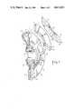
- FIG. 1is a perspective view, partially broken out and exploded, of a brake disc according to the invention
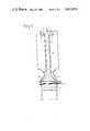
- FIG. 2is a half-cross-sectional view, taken axially, of one of the spokes of the disc core;
- FIG. 3is a detailed of a spoke and its associated disc parts, taken in circular cross section, orthogonally to said spoke;
- FIG. 4is a detailed view taken along line IV--IV of FIG. 3.
- the disccomprises a metal core 1 consisting of six or eight radial arms or spokes 2 spaced equally apart around a center ring 3, which acts as a hub.
- Said spokes 2have a rectangular section (ie. they have top and bottom surfaces 4 and edges 5) and end in a flange 6, shaped as a double hook with points toward the center of the disc establishing an oblique bearing 7 on each side of the core.
- the spokes 2can withstand substantial mechanical stresses and transmit them to the hub 3 which transfers them to the axle attached thereto, but not shown in the drawing.
- the friction padsconsist of sectors 8 (each disc face can have three or four sectors) fitted on each side of the spokes 2 of the metal core 1.
- FIG. 1shows sectors 8 as fitted, attached to both sides of the disc, and in the exploded view, two similar sectors oriented two different ways to show their outside friction surface 11 and their inside, mounting surface or back 10, respectively.
- Said sectors 8are lockably mounted near the ends of the spokes 2 against the spoke flanges 6, being hooked and held both radially and axially by their outer edges.
- the bearing parts 7 of the hooksare inclined at an angle in relation to the axis of the disc ensuring not only a secure holding of the sectors 8, but also easy mounting of the sectors.
- Said oblique bearing surfaces 7 in the flanges 6cooperate with matching oblique bearing surfaces 9 on the outer edge of the sectors 8.
- Back-to-back sectors 8are circumferentially offset by an angle equal to the angular spacing of the spokes (60° or 45°), or stated otherwise, by half the angular breadth of a sector 8.
- This arrangementprovides a good bending strength for the sectors or pads 8 as well as suitable parallelism of the friction surfaces 11 and precludes too-violent contact of the brake shoes with the sectors' chamfered edges 13 (FIG. 3). Furthermore, in bearing on each other, the sector 8 backs 10 are kept from contacting the supporting spokes 2, thus reducing heat transfer to the metal core and promoting spoke ventilation.
- each sector pad 8transmits the friction forces it receives to only one of the spokes 2 of the metal core 1.
- only the center slot 15 of sector pads 8has walls 17 in actual contact with the edges 5 of the nested spoke 2--a feature which allows the pad 8 to work in compression in the same way regardless of the disc's direction of rotation.
- the spokes 2thus alternatingly take up the frictional forces from the sectors on opposite faces of the disc.
- further self-ventilationcan be provided by adding grooves or channels 18 in the backs 10 of the sectors 8.
- each pad 8may come into radial contact with as many as three spoke flanges.
- This arrangementmay not always be compatible with the requirement for unconstrained differential expansion. Therefore, it may be envisaged that, in order to obtain and maintain the same radial contacts between the spoke flanges 6 and the pads 8 in spite of the thermal variations occurring during braking, the inclined bearing surface 9 at the center of the pad (in line with the center slot 15) facing the inclined bearing surface 7 of the flange 6 of the corresponding spoke be provided with a relief, or, alternatively, that the inclined bearing surfaces 9 at the ends of the pad 8 (in line with the end slots 16), facing the inclined bearing surfaces 7 of the flanges 6 of their corresponding spokes be provided with a relief.
- the inclined bearing surface 9 at the center of the padin line with the center slot 15
- the inclined bearing surfaces 9 at the ends of the pad 8in line with the end slots 16
- elastic or spring-like rings 19are brought to bear against a tapered bearing surface 20 machined around the internal periphery of the sector pads 8, the angle of said tapered surface being defined to allow the pads to move freely relative to one another.
- the spring rings 19are supported by the hub ring 3 of the metal core 1 and fastened by bolts 21. They allow the self-centering of the sectors 8 while leaving them free to expand in relation to the core 1, thus avoiding an accumulation of stresses.
- These spring ringsare provided with holes 22 for the bolts 21 and feature radial fingers serving as bent leaf springs the ends whereof push against the tapered bearing surface 20.
- the spring rings 19are type 15CDV6 or 28CDV5 refractory steel drop forgings. Their reproducibility is thus established.
- the disc according to the inventionis perfectly suited for use in railway vehicle brake systems and particularly in high-speed trains.
Landscapes
- Engineering & Computer Science (AREA)
- General Engineering & Computer Science (AREA)
- Mechanical Engineering (AREA)
- Chemical & Material Sciences (AREA)
- Composite Materials (AREA)
- Materials Engineering (AREA)
- Braking Arrangements (AREA)
Abstract
Description
Claims (5)
Applications Claiming Priority (2)
| Application Number | Priority Date | Filing Date | Title |
|---|---|---|---|
| FR8320496AFR2557240B1 (en) | 1983-12-21 | 1983-12-21 | BRAKE DISC WITH REMOVABLE LININGS |
| FR8320496 | 1983-12-21 |
Publications (1)
| Publication Number | Publication Date |
|---|---|
| US4613021Atrue US4613021A (en) | 1986-09-23 |
Family
ID=9295409
Family Applications (1)
| Application Number | Title | Priority Date | Filing Date |
|---|---|---|---|
| US06/678,233Expired - LifetimeUS4613021A (en) | 1983-12-21 | 1984-12-05 | Brake disc with removable pads |
Country Status (6)
| Country | Link |
|---|---|
| US (1) | US4613021A (en) |
| JP (1) | JPS60157529A (en) |
| DE (1) | DE3446872C2 (en) |
| FR (1) | FR2557240B1 (en) |
| GB (1) | GB2151729B (en) |
| IT (1) | IT1178764B (en) |
Cited By (33)
| Publication number | Priority date | Publication date | Assignee | Title |
|---|---|---|---|---|
| US4763762A (en)* | 1987-11-10 | 1988-08-16 | The United States Of America As Represented By The United States National Aeronautics And Space Administration | Preloaded brake disc |
| US4848553A (en)* | 1988-03-29 | 1989-07-18 | Dana Corporation | Friction laminate and disk assembly |
| US4860872A (en)* | 1987-12-15 | 1989-08-29 | Dana Corporation | Friction disc assembly |
| US5052525A (en)* | 1989-09-12 | 1991-10-01 | Ekola Kenneth E | Quick release torque post assembly for web tension brake pads |
| US5332067A (en)* | 1991-06-28 | 1994-07-26 | Carbone Industrie | Disk-brake pad device especially with a carbon-carbon lining |
| US5515953A (en)* | 1991-06-25 | 1996-05-14 | Shinko Denki Kabushiki Kaisha | Frictional force transmitting device used in vacuum |
| US5547717A (en)* | 1992-10-09 | 1996-08-20 | Avco Corporation | Method for densifying and refurbishing brakes |
| DE19652464A1 (en)* | 1996-12-17 | 1998-06-18 | Bayerische Motoren Werke Ag | Compound brake disc |
| EP1150027A1 (en)* | 2000-04-26 | 2001-10-31 | Raybestos Industrie-Produkte GmbH | Clutch plate for a friction clutch |
| FR2812697A1 (en)* | 2000-08-03 | 2002-02-08 | Mannesmann Sachs Ag | CLUTCH DISC |
| US20040173418A1 (en)* | 2001-08-31 | 2004-09-09 | Christoph Saame | Brake disc |
| US20050029060A1 (en)* | 2001-10-02 | 2005-02-10 | Johann Baumgartner | Brake disc for a disc brake |
| US6935470B1 (en) | 2002-12-31 | 2005-08-30 | Robert P. Smith, Jr. | Disk brake |
| US20050205368A1 (en)* | 2002-09-10 | 2005-09-22 | Joakim Gripemark | Supported disc |
| WO2006012604A1 (en)* | 2004-07-22 | 2006-02-02 | Bendix Spicer Foundation Brake, Llc | Disc brake rotor assembly with replaceable wear surfaces |
| US20080135359A1 (en)* | 2006-12-11 | 2008-06-12 | Basirico John T | Brake rotor with ceramic matrix composite friction surface plates |
| US20090139807A1 (en)* | 2007-12-03 | 2009-06-04 | Honeywell International Inc | Brake assembly having multi-piece core and replaceable friction surfaces |
| US20110056777A1 (en)* | 2009-09-08 | 2011-03-10 | Gm Global Technology Operations, Inc. | Bimetallic Brake Rotor |
| US20110142626A1 (en)* | 2009-04-02 | 2011-06-16 | Hanson Jesse M | Serviceable yaw brake disc segments without nacelle removal |
| US9587691B2 (en)* | 2015-01-27 | 2017-03-07 | Goodrich Corporation | Friction disks with floating wear linings |
| US20170184163A1 (en)* | 2015-12-28 | 2017-06-29 | Goodrich Corporation | Plate assemblies including floating wear linings for multi-disk brake systems and methods for reducing vibration in a multi-disk brake system |
| US20170184164A1 (en)* | 2014-05-19 | 2017-06-29 | Tech M3, Inc | Brake Rotor With Working Surface Inserts |
| CN108533649A (en)* | 2017-03-02 | 2018-09-14 | 霍尼韦尔国际公司 | Carbon-carbon composite disc brake component |
| CN108561460A (en)* | 2018-06-07 | 2018-09-21 | 北京天宜上佳高新材料股份有限公司 | A kind of combined type brake disc and brake apparatus |
| US10316908B2 (en)* | 2014-09-10 | 2019-06-11 | Meggitt Aircraft Braking Systems Corporation | Aircraft brake assembly structures for reducing noise |
| US20190368560A1 (en)* | 2013-03-15 | 2019-12-05 | Tech M3, Inc. | Wear resistant braking systems |
| CN111425539A (en)* | 2020-06-11 | 2020-07-17 | 莱州伟辰汽车配件有限公司 | Split assembled brake disc |
| US11125289B2 (en) | 2019-07-03 | 2021-09-21 | Honeywell International Inc. | Brake disc assembly |
| US11235870B2 (en)* | 2018-06-28 | 2022-02-01 | Textron Innovations Inc. | Droop ring with removable wear elements |
| US11384805B2 (en) | 2019-11-21 | 2022-07-12 | Honeywell International Inc. | Brake disc assembly |
| US20230141095A1 (en)* | 2019-10-14 | 2023-05-11 | Volvo Truck Corporation | Brake disc and a vehicle |
| US12203517B2 (en) | 2019-10-14 | 2025-01-21 | Volvo Truck Corporation | Brake disc and a vehicle |
| US12203516B2 (en) | 2019-10-14 | 2025-01-21 | Volvo Truck Corporation | Brake disc and a vehicle |
Families Citing this family (20)
| Publication number | Priority date | Publication date | Assignee | Title |
|---|---|---|---|---|
| DE3762544D1 (en)* | 1986-02-05 | 1990-06-07 | Europ Propulsion | FRICTION SYSTEM FROM COMPOSED FIRE-RESISTANT MATERIALS. |
| DE3722031A1 (en)* | 1987-07-03 | 1989-01-12 | Bayerische Motoren Werke Ag | BRAKE DISC |
| FR2626637B1 (en)* | 1988-02-02 | 1993-04-16 | Carbone Ind | DISC BRAKE FOR ROTATING SHAFT |
| GB2228053B (en)* | 1989-02-08 | 1993-04-14 | Automotive Products Plc | Brake disc |
| DE4027677C2 (en)* | 1990-08-31 | 1994-02-17 | Bayerische Motoren Werke Ag | Brake disc for disc brakes in motor vehicles |
| FR2728945A1 (en)* | 1994-12-28 | 1996-07-05 | Renault Vehicules Ind | Ventilated brake disc, esp. for motor vehicle |
| US5779006A (en)* | 1995-05-24 | 1998-07-14 | The B. F. Goodrich Company | Composite friction disk having replaceable wear faces |
| US5558186A (en)* | 1995-05-24 | 1996-09-24 | The Bfgoodrich Company | Friction disk with renewable wear faces |
| DE19652106C2 (en)* | 1996-12-14 | 1999-04-08 | Mannesmann Sachs Ag | Clutch disc for friction clutches |
| DE19721647C2 (en)* | 1997-05-23 | 2002-06-27 | Deutsch Zentr Luft & Raumfahrt | Solid construction friction unit, in particular brake disc, with several friction bodies |
| DE19842982C2 (en)* | 1998-09-19 | 2000-10-26 | Daimler Chrysler Ag | Brake disc with removable and split friction disc wear pads |
| DE10038490A1 (en)* | 2000-08-08 | 2002-02-21 | Wabco Gmbh & Co Ohg | Full disk brake for a vehicle, has air cooling channels between the brake lining segments to provide cooling air between the rotor disk and the friction disks |
| DE102004038484B3 (en)* | 2004-08-07 | 2006-04-13 | Audi Ag | Disc brake for motor vehicles |
| ITMI20050280A1 (en)* | 2005-02-23 | 2006-08-24 | Sunstar Logistic Singapore Pte Ltd | BRAKE FOR WHEELS OF VEHICLES PROVIDED WITH A BRAKE DISC WITH SECTORS |
| CN102272471B (en)* | 2008-12-12 | 2015-06-17 | 雷·阿贝斯曼 | Modular brake pad |
| WO2010108671A1 (en)* | 2009-03-27 | 2010-09-30 | Faiveley Transport Witten Gmbh | Brake disk |
| DE102013216591A1 (en)* | 2013-02-14 | 2014-08-28 | Continental Teves Ag & Co. Ohg | Internally ventilated brake disk for motor vehicle, has support body with cooling channels for friction ring segments which are provided with friction surface for attachment of friction lining |
| ITUA20163766A1 (en)* | 2016-05-25 | 2017-11-25 | Ferdiam S R L | SUPPORT FOR BRUSH DRAIN BRAKING TRACKS, RELATED BRAKE AND DISC BRAKE ELEMENT |
| WO2024049711A1 (en)* | 2022-08-31 | 2024-03-07 | AscenZ Friction & Brake LLC | Friction element capturing and positioning assembly and methods of manufacturing thereof |
| DE102023123190B4 (en)* | 2023-08-29 | 2025-03-13 | Schaeffler Technologies AG & Co. KG | Braking device with a plurality of brake discs and vehicle with the braking device |
Citations (10)
| Publication number | Priority date | Publication date | Assignee | Title |
|---|---|---|---|---|
| US1625933A (en)* | 1925-04-20 | 1927-04-26 | Magnet Werk Gmbh Eisenach | Friction body for multiple-disk clutches and the like |
| US2485082A (en)* | 1946-05-08 | 1949-10-18 | American Steel Foundries | Composite brake rotor |
| US2708492A (en)* | 1951-05-29 | 1955-05-17 | American Steel Foundries | Brake rotor with removable friction members |
| US2893519A (en)* | 1954-09-27 | 1959-07-07 | Bendix Aviat Corp | Brake assembly |
| US3295641A (en)* | 1965-03-01 | 1967-01-03 | Girling Ltd | Wheels |
| US3403759A (en)* | 1967-02-13 | 1968-10-01 | Bendix Corp | Disc element construction for disc brake |
| US3599766A (en)* | 1969-09-02 | 1971-08-17 | Goodrich Co B F | Segmented friction member for brake or clutch |
| US3759354A (en)* | 1971-03-02 | 1973-09-18 | Dunlop Ltd | Brake disc structure |
| FR2295304A1 (en)* | 1974-12-20 | 1976-07-16 | Girling Ltd | DISC BRAKE IMPROVEMENTS |
| FR2326623A1 (en)* | 1975-10-01 | 1977-04-29 | Girling Ltd | Friction disc for expansion brakes - has projections on faces of linings located in holes in support plate with linings held by spring clips |
Family Cites Families (8)
| Publication number | Priority date | Publication date | Assignee | Title |
|---|---|---|---|---|
| US2767817A (en)* | 1951-09-26 | 1956-10-23 | Clark Equipment Co | Friction disc with removable lining |
| AT284786B (en)* | 1968-09-16 | 1970-09-25 | Degussa | Process for obtaining non-aqueous hydrogen peroxide solutions |
| GB1496341A (en)* | 1974-06-04 | 1977-12-30 | Girling Ltd | Spreading disc brakes |
| CA1060814A (en)* | 1975-09-18 | 1979-08-21 | Goodyear Aerospace Corporation | Rigid segmented brake disk |
| FR2357789A1 (en)* | 1976-07-07 | 1978-02-03 | Pont A Mousson | DISC FOR DISC BRAKE |
| US4132294A (en)* | 1976-07-23 | 1979-01-02 | Poli Off Mecc Spa | Braking disc with replaceable linings, for brake-discs |
| US4297307A (en)* | 1979-06-29 | 1981-10-27 | Union Carbide Corporation | Process for producing carbon-carbon fiber composites suitable for use as aircraft brake discs |
| DE2947606C2 (en)* | 1979-11-26 | 1982-08-19 | Alfred Teves Gmbh, 6000 Frankfurt | Annular friction body, especially for full disc brakes |
- 1983
- 1983-12-21FRFR8320496Apatent/FR2557240B1/ennot_activeExpired
- 1984
- 1984-12-05GBGB08430659Apatent/GB2151729B/ennot_activeExpired
- 1984-12-05USUS06/678,233patent/US4613021A/ennot_activeExpired - Lifetime
- 1984-12-17ITIT24085/84Apatent/IT1178764B/enactive
- 1984-12-21DEDE3446872Apatent/DE3446872C2/ennot_activeExpired - Fee Related
- 1984-12-21JPJP59271639Apatent/JPS60157529A/enactiveGranted
Patent Citations (11)
| Publication number | Priority date | Publication date | Assignee | Title |
|---|---|---|---|---|
| US1625933A (en)* | 1925-04-20 | 1927-04-26 | Magnet Werk Gmbh Eisenach | Friction body for multiple-disk clutches and the like |
| US2485082A (en)* | 1946-05-08 | 1949-10-18 | American Steel Foundries | Composite brake rotor |
| US2708492A (en)* | 1951-05-29 | 1955-05-17 | American Steel Foundries | Brake rotor with removable friction members |
| US2893519A (en)* | 1954-09-27 | 1959-07-07 | Bendix Aviat Corp | Brake assembly |
| US3295641A (en)* | 1965-03-01 | 1967-01-03 | Girling Ltd | Wheels |
| US3403759A (en)* | 1967-02-13 | 1968-10-01 | Bendix Corp | Disc element construction for disc brake |
| US3599766A (en)* | 1969-09-02 | 1971-08-17 | Goodrich Co B F | Segmented friction member for brake or clutch |
| US3759354A (en)* | 1971-03-02 | 1973-09-18 | Dunlop Ltd | Brake disc structure |
| FR2295304A1 (en)* | 1974-12-20 | 1976-07-16 | Girling Ltd | DISC BRAKE IMPROVEMENTS |
| US4018311A (en)* | 1974-12-20 | 1977-04-19 | Girling Limited | Rotor and braking ring disc assembly |
| FR2326623A1 (en)* | 1975-10-01 | 1977-04-29 | Girling Ltd | Friction disc for expansion brakes - has projections on faces of linings located in holes in support plate with linings held by spring clips |
Cited By (56)
| Publication number | Priority date | Publication date | Assignee | Title |
|---|---|---|---|---|
| US4763762A (en)* | 1987-11-10 | 1988-08-16 | The United States Of America As Represented By The United States National Aeronautics And Space Administration | Preloaded brake disc |
| US4860872A (en)* | 1987-12-15 | 1989-08-29 | Dana Corporation | Friction disc assembly |
| US4848553A (en)* | 1988-03-29 | 1989-07-18 | Dana Corporation | Friction laminate and disk assembly |
| US5052525A (en)* | 1989-09-12 | 1991-10-01 | Ekola Kenneth E | Quick release torque post assembly for web tension brake pads |
| US5515953A (en)* | 1991-06-25 | 1996-05-14 | Shinko Denki Kabushiki Kaisha | Frictional force transmitting device used in vacuum |
| US5332067A (en)* | 1991-06-28 | 1994-07-26 | Carbone Industrie | Disk-brake pad device especially with a carbon-carbon lining |
| US5547717A (en)* | 1992-10-09 | 1996-08-20 | Avco Corporation | Method for densifying and refurbishing brakes |
| DE19652464A1 (en)* | 1996-12-17 | 1998-06-18 | Bayerische Motoren Werke Ag | Compound brake disc |
| EP1150027A1 (en)* | 2000-04-26 | 2001-10-31 | Raybestos Industrie-Produkte GmbH | Clutch plate for a friction clutch |
| WO2001081782A1 (en)* | 2000-04-26 | 2001-11-01 | Raybestos Industrie-Produkte Gmbh | Clutch disk for engaging and disengaging friction clutches |
| US6568521B2 (en) | 2000-08-03 | 2003-05-27 | Mannesmann Sachs Ag | Clutch disk |
| FR2812697A1 (en)* | 2000-08-03 | 2002-02-08 | Mannesmann Sachs Ag | CLUTCH DISC |
| GB2365501B (en)* | 2000-08-03 | 2004-10-13 | Mannesmann Sachs Ag | Clutch disc assembly |
| GB2365501A (en)* | 2000-08-03 | 2002-02-20 | Mannesmann Sachs Ag | Mounting a friction lining to a clutch disc using a wedging technique |
| US7040466B2 (en)* | 2001-08-31 | 2006-05-09 | Audi Ag | Brake disc |
| US20040173418A1 (en)* | 2001-08-31 | 2004-09-09 | Christoph Saame | Brake disc |
| US20050029060A1 (en)* | 2001-10-02 | 2005-02-10 | Johann Baumgartner | Brake disc for a disc brake |
| US7228946B2 (en)* | 2001-10-02 | 2007-06-12 | Knorr-Bremse Systeme Fuer Nutzfahrzeuge Gmbh | Brake disc for a disc brake |
| US20050205368A1 (en)* | 2002-09-10 | 2005-09-22 | Joakim Gripemark | Supported disc |
| US7261193B2 (en)* | 2002-09-10 | 2007-08-28 | Haldex Brake Products Ab | Supported disc |
| US6935470B1 (en) | 2002-12-31 | 2005-08-30 | Robert P. Smith, Jr. | Disk brake |
| WO2006012604A1 (en)* | 2004-07-22 | 2006-02-02 | Bendix Spicer Foundation Brake, Llc | Disc brake rotor assembly with replaceable wear surfaces |
| US7159698B2 (en) | 2004-07-22 | 2007-01-09 | Bendix Spicer Foundation Brake, Llc | Disc brake rotor assembly with replaceable wear surfaces |
| US20080135359A1 (en)* | 2006-12-11 | 2008-06-12 | Basirico John T | Brake rotor with ceramic matrix composite friction surface plates |
| US20090139807A1 (en)* | 2007-12-03 | 2009-06-04 | Honeywell International Inc | Brake assembly having multi-piece core and replaceable friction surfaces |
| US8281907B2 (en) | 2007-12-03 | 2012-10-09 | Honeywell International Inc. | Brake assembly having multi-piece core and replaceable friction surfaces |
| US20110142626A1 (en)* | 2009-04-02 | 2011-06-16 | Hanson Jesse M | Serviceable yaw brake disc segments without nacelle removal |
| US8408369B2 (en)* | 2009-09-08 | 2013-04-02 | GM Global Technology Operations LLC | Bimetallic brake rotor |
| DE102010035816B4 (en)* | 2009-09-08 | 2015-02-19 | GM Global Technology Operations LLC (n. d. Ges. d. Staates Delaware) | Two-metal brake rotor |
| US20110056777A1 (en)* | 2009-09-08 | 2011-03-10 | Gm Global Technology Operations, Inc. | Bimetallic Brake Rotor |
| US11624416B2 (en) | 2013-03-15 | 2023-04-11 | Tech M3, Inc. | Wear resistant braking systems |
| US12110933B2 (en) | 2013-03-15 | 2024-10-08 | Tech M3, Inc. | Wear resistant braking systems |
| US10895295B2 (en) | 2013-03-15 | 2021-01-19 | Tech M3, Inc. | Wear resistant braking systems |
| US20190368560A1 (en)* | 2013-03-15 | 2019-12-05 | Tech M3, Inc. | Wear resistant braking systems |
| US20170184164A1 (en)* | 2014-05-19 | 2017-06-29 | Tech M3, Inc | Brake Rotor With Working Surface Inserts |
| US12270443B2 (en)* | 2014-05-19 | 2025-04-08 | Tech M3, Inc. | Brake rotor with working surface inserts |
| US10316908B2 (en)* | 2014-09-10 | 2019-06-11 | Meggitt Aircraft Braking Systems Corporation | Aircraft brake assembly structures for reducing noise |
| US9587691B2 (en)* | 2015-01-27 | 2017-03-07 | Goodrich Corporation | Friction disks with floating wear linings |
| US10544844B2 (en) | 2015-12-28 | 2020-01-28 | Goodrich Corporation | Plate assemblies including floating wear linings for multi-disk brake systems and methods for reducing vibration in a multi-disk brake system |
| US10167912B2 (en) | 2015-12-28 | 2019-01-01 | Goodrich Corporation | Plate assemblies including floating wear linings for multi-disk brake systems and methods for reducing vibration in a multi-disk brake system |
| US9909632B2 (en)* | 2015-12-28 | 2018-03-06 | Goodrich Corporation | Plate assemblies including floating wear linings for multi-disk brake systems and methods for reducing vibration in a multi-disk brake system |
| US20170184163A1 (en)* | 2015-12-28 | 2017-06-29 | Goodrich Corporation | Plate assemblies including floating wear linings for multi-disk brake systems and methods for reducing vibration in a multi-disk brake system |
| CN108533649B (en)* | 2017-03-02 | 2022-02-11 | 霍尼韦尔国际公司 | Carbon-carbon composite disc brake assembly |
| US10094439B2 (en)* | 2017-03-02 | 2018-10-09 | Honeywell International Inc. | Carbon-carbon composite disc brake assembly |
| CN108533649A (en)* | 2017-03-02 | 2018-09-14 | 霍尼韦尔国际公司 | Carbon-carbon composite disc brake component |
| CN108561460A (en)* | 2018-06-07 | 2018-09-21 | 北京天宜上佳高新材料股份有限公司 | A kind of combined type brake disc and brake apparatus |
| CN108561460B (en)* | 2018-06-07 | 2024-02-20 | 北京天宜上佳高新材料股份有限公司 | A combined brake disc and braking device |
| US11235870B2 (en)* | 2018-06-28 | 2022-02-01 | Textron Innovations Inc. | Droop ring with removable wear elements |
| US11746843B2 (en) | 2019-07-03 | 2023-09-05 | Honeywell International Inc. | Brake disc assembly |
| US11125289B2 (en) | 2019-07-03 | 2021-09-21 | Honeywell International Inc. | Brake disc assembly |
| US20230141095A1 (en)* | 2019-10-14 | 2023-05-11 | Volvo Truck Corporation | Brake disc and a vehicle |
| US12203517B2 (en) | 2019-10-14 | 2025-01-21 | Volvo Truck Corporation | Brake disc and a vehicle |
| US12203518B2 (en)* | 2019-10-14 | 2025-01-21 | Volvo Truck Corporation | Brake disc and a vehicle |
| US12203516B2 (en) | 2019-10-14 | 2025-01-21 | Volvo Truck Corporation | Brake disc and a vehicle |
| US11384805B2 (en) | 2019-11-21 | 2022-07-12 | Honeywell International Inc. | Brake disc assembly |
| CN111425539A (en)* | 2020-06-11 | 2020-07-17 | 莱州伟辰汽车配件有限公司 | Split assembled brake disc |
Also Published As
| Publication number | Publication date |
|---|---|
| IT1178764B (en) | 1987-09-16 |
| GB2151729B (en) | 1987-12-09 |
| JPS60157529A (en) | 1985-08-17 |
| IT8424085A0 (en) | 1984-12-17 |
| GB2151729A (en) | 1985-07-24 |
| FR2557240A1 (en) | 1985-06-28 |
| GB8430659D0 (en) | 1985-01-16 |
| DE3446872A1 (en) | 1985-07-11 |
| IT8424085A1 (en) | 1986-06-17 |
| DE3446872C2 (en) | 1996-10-31 |
| JPH0445696B2 (en) | 1992-07-27 |
| FR2557240B1 (en) | 1989-05-19 |
Similar Documents
| Publication | Publication Date | Title |
|---|---|---|
| US4613021A (en) | Brake disc with removable pads | |
| CA1211386A (en) | Disc brake assembly | |
| US6446765B1 (en) | Device for fixing a ventilated brake disk axially on the hub of a motor vehicle wheel | |
| EP0701072B1 (en) | Brake rotor | |
| US4865160A (en) | Dual disk brake | |
| US4878563A (en) | Brake apparatus | |
| US6135247A (en) | Wheel hub and brake disc arrangement for heavy vehicles | |
| EP1395761B1 (en) | A disk-brake disk with air cooling | |
| RU2003101401A (en) | FAST-FIXED DISC BRAKE WITH A SMALL MUTUAL COVERAGE COEFFICIENT | |
| US20070284200A1 (en) | Brake disc assembly and method of construction | |
| US5085295A (en) | Brake rotor and stator discs with multiple rings joined by pins | |
| US3605968A (en) | Segmented friction member for brake or clutch | |
| JP2018538498A (en) | Brake rotor for vehicle | |
| US3726374A (en) | Circular segmented friction member for brake or clutch | |
| US6135248A (en) | Brake disk | |
| US3599766A (en) | Segmented friction member for brake or clutch | |
| US4077501A (en) | Disc for disc brake unit | |
| US20080217116A1 (en) | Parking Brake | |
| JP2009287621A (en) | Disc rotor for disc brake | |
| GB2161560A (en) | Wheel and brake assembly | |
| CN112178092B (en) | Brake disc assembly | |
| US4600090A (en) | Brake lining support in disc brakes | |
| EP3628886B1 (en) | Friction discs with angled stator lugs | |
| GB2172676A (en) | Improvements relating to discs for disc brakes | |
| US2350970A (en) | Rotor |
Legal Events
| Date | Code | Title | Description |
|---|---|---|---|
| AS | Assignment | Owner name:SOCIETE EUROPEENNE DE PROPULSION, 3, AVENUE DU GEN Free format text:ASSIGNMENT OF ASSIGNORS INTEREST.;ASSIGNORS:LACOMBE, ALAIN;VIVES, MICHEL;REEL/FRAME:004342/0377 Effective date:19841123 | |
| STCF | Information on status: patent grant | Free format text:PATENTED CASE | |
| FEPP | Fee payment procedure | Free format text:PAYOR NUMBER ASSIGNED (ORIGINAL EVENT CODE: ASPN); ENTITY STATUS OF PATENT OWNER: LARGE ENTITY | |
| FPAY | Fee payment | Year of fee payment:4 | |
| FEPP | Fee payment procedure | Free format text:PAYER NUMBER DE-ASSIGNED (ORIGINAL EVENT CODE: RMPN); ENTITY STATUS OF PATENT OWNER: LARGE ENTITY Free format text:PAYOR NUMBER ASSIGNED (ORIGINAL EVENT CODE: ASPN); ENTITY STATUS OF PATENT OWNER: LARGE ENTITY | |
| FPAY | Fee payment | Year of fee payment:8 | |
| FPAY | Fee payment | Year of fee payment:12 | |
| AS | Assignment | Owner name:SOCIETE NATIONALE D'ETUDE ET DE CONSTRUCTION DE MO Free format text:MERGER WITH AN EXTRACT FROM THE FRENCH TRADE REGISTER AND ITS ENGLISH TRANSLATION;ASSIGNOR:SOCIETE EUROPEENNE DE PROPULSION;REEL/FRAME:009490/0516 Effective date:19971031 | |
| FEPP | Fee payment procedure | Free format text:PAYER NUMBER DE-ASSIGNED (ORIGINAL EVENT CODE: RMPN); ENTITY STATUS OF PATENT OWNER: LARGE ENTITY Free format text:PAYOR NUMBER ASSIGNED (ORIGINAL EVENT CODE: ASPN); ENTITY STATUS OF PATENT OWNER: LARGE ENTITY | |
| FEPP | Fee payment procedure | Free format text:PAYOR NUMBER ASSIGNED (ORIGINAL EVENT CODE: ASPN); ENTITY STATUS OF PATENT OWNER: LARGE ENTITY Free format text:PAYER NUMBER DE-ASSIGNED (ORIGINAL EVENT CODE: RMPN); ENTITY STATUS OF PATENT OWNER: LARGE ENTITY |