US4611875A - Communication system cross-connect field power adapter - Google Patents
Communication system cross-connect field power adapterDownload PDFInfo
- Publication number
- US4611875A US4611875AUS06/643,446US64344684AUS4611875AUS 4611875 AUS4611875 AUS 4611875AUS 64344684 AUS64344684 AUS 64344684AUS 4611875 AUS4611875 AUS 4611875A
- Authority
- US
- United States
- Prior art keywords
- jack
- plug
- adapter
- contacts
- cord
- Prior art date
- Legal status (The legal status is an assumption and is not a legal conclusion. Google has not performed a legal analysis and makes no representation as to the accuracy of the status listed.)
- Expired - Lifetime
Links
- 238000004891communicationMethods0.000titleclaimsdescription10
- 239000004020conductorSubstances0.000claimsabstractdescription25
- 230000013011matingEffects0.000claimsabstractdescription9
- 238000003780insertionMethods0.000claimsabstractdescription3
- 230000037431insertionEffects0.000claimsabstractdescription3
- 238000000034methodMethods0.000claims2
- 238000005516engineering processMethods0.000abstractdescription5
- 238000002788crimpingMethods0.000description2
- 239000003086colorantSubstances0.000description1
- 239000000463materialSubstances0.000description1
- 239000002184metalSubstances0.000description1
- 230000000717retained effectEffects0.000description1
Images


Classifications
- H—ELECTRICITY
- H01—ELECTRIC ELEMENTS
- H01R—ELECTRICALLY-CONDUCTIVE CONNECTIONS; STRUCTURAL ASSOCIATIONS OF A PLURALITY OF MUTUALLY-INSULATED ELECTRICAL CONNECTING ELEMENTS; COUPLING DEVICES; CURRENT COLLECTORS
- H01R31/00—Coupling parts supported only by co-operation with counterpart
- H01R31/02—Intermediate parts for distributing energy to two or more circuits in parallel, e.g. splitter
- H—ELECTRICITY
- H01—ELECTRIC ELEMENTS
- H01R—ELECTRICALLY-CONDUCTIVE CONNECTIONS; STRUCTURAL ASSOCIATIONS OF A PLURALITY OF MUTUALLY-INSULATED ELECTRICAL CONNECTING ELEMENTS; COUPLING DEVICES; CURRENT COLLECTORS
- H01R13/00—Details of coupling devices of the kinds covered by groups H01R12/70 or H01R24/00 - H01R33/00
- H01R13/02—Contact members
- H01R13/26—Pin or blade contacts for sliding co-operation on one side only
Definitions
- This inventionrelates to an arrangement for providing power to telephone stations and more particularly to such an arrangement where the power is provided via a cross-connect field power adapter plug/jack.
- a power adapter plug/jackwhich is designed to be plugged into the telephone jack positions of a cross-connect field and which has a front plug having eight terminals and a rear jack adapted to receive the standard six terminal cross-connect cord plug.
- the power adapterhas a two conductor cord permanently attached which serves to supply power to two of the eight terminals of the front jack with the other six terminals being connectable to the six terminal cross-connect cord plug.
- the other end of the two conductor cordterminates in a connector adapted for mating with the power take-off position.
- the plug/jack adaptercombines two types of technology to connect the plug, the jack and the power cord.
- Bent wire technologyis used to provide electrical continuity between the six position rear jack and the center six positions of the eight position front plug. Electrical continuity between the two conductor power cord and positions one and eight of the front plug is made using blade insertion technology.
- the two conductorsare inserted from the rear into molded-in channels along the bottom surface of the plug/jack and are pushed in until they emerge from the front of the plug. Individual metal blades are then pushed into each wire, thereby securing the wire ends and providing electric contacts for supplying the power to the station.
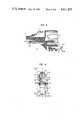
- FIG. 1is a perspective view of the cross-connect power adapter
- FIG. 2is a schematic representation showing one environment in which the adapter can be utilized
- FIG. 3is a sectional view of the power adapter taken through section 3--3 of FIG. 4;
- FIG. 4is a view of the power adapter from the right (rear) side (in relation to FIG. 1);
- FIG. 5is a left side (front) view of the power adapter (in relation to FIG. 1);
- FIG. 6is a bottom view of the power adapter.
- FIG. 7is a sectional view taken through section 7--7 of FIG. 4.
- FIG. 1shows a perspective view of power adapter 10 where front plug-end 11 is adapted for mating with any jack of a cross-connect field in the manner to be discussed. Opposite the plug-end of power adapter 10 there is a jack-end 30 adapted to receive the plug-end 216-1 of double plug-ended cross-connect cord 102.
- Cable 101extends from adapter 10 at a position below jack 30.
- cable 101there are at least two conductors 101A and 101B which, as will be seen, extend through the body of adapter 10 and terminate at contacts 63 and 62, respectively, at the plug-end of the adapter.
- the six contacts of cross-connect cord plug 216-1mate with six contacts within jack 30 which contacts extend through the body of adapter 10 terminating as contacts 50-55 at the plug-end 11 of adapter 10.
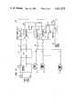
- FIG. 2where central office trunks T1-TN are shown terminating at network interface 210 where the individual trunks are combined into multi-conductor cables which are in turn connected to PBX 211.
- Line 212 from PBX 211are plugged into cross-connect field 215 and are in turn connected to individual jack sets 20, 21.
- Lines L1-LN from each telephone station set S1-SNare also plugged into cross-connect field 215 using different jack sets 22, 23 for termination.
- Each cable 212, 213is connected to a particular jack set 20, 21, 22 and 23 and the cable pairs within the cable are connected to individual jacks. For example, in multiples of eight, the conductors of cable 213 are connected to jacks 22-1, 22-2, 22-3, 22-4 and 22-5.
- a six conductor double plug-ended patch cordsuch as patch cord 216 or 103, is then used to interconnect any jack associated with a station line with any jack associated with a PBX line.
- station jack 22-2is cross-connected to trunk jack 20-4 via double-ended cord 103. The user then, by simply changing one end of the patch cord, may change the association between any PBX (or CO) line and the station.
- adapter 10When it is desired to add power to a telephone station, adapter 10 would be inserted in the connection associated with the station, for example, between the plug-end 216-1 of cross-connect cord 216 and cross-connect jack 23-3. The plug-end of adapter 10 would then be inserted into jack 23-3 and plug 216-1 would be inserted into the jack-end of adapter 10. Auxiliary cord 101 extending from adapter 10 would then be connected to the power take-off point, such as connector 24-2. This connection could be made using the same type of quick connect or any type of plug/jack combination.
- a craftsperson using the power adapterwould then not be required to make any splices and would be able to supply to any station simply by removing one plug (216-1) and reinserting the same plug into adapter 10.
- the craftsperson or customercan easily observe which ones of the telephone stations are obtaining auxiliary power at any given time.
- FIG. 3it will be seen that within jack 30 there exists a number of parallel contacts, such as contacts 51, which are constructed from spring material and which extend from jack-end 30 of adapter 10 through the body of the adapter to plug-end 11. As will be seen, the bottom portion of plug-end 11 is open so that contact can be made with the contacts of a mating jack when plug-end 11 is inserted into the jack.
- contacts 51which are constructed from spring material and which extend from spring material and which extend from spring material and which extend from spring material and which extend from spring material and which extend from spring material and which extend from spring material and which extend from spring material and which extend from spring material and which extend from spring material and which extend from spring material and which extend from spring material and which extend from spring material and which extend from spring material and which extend from spring material and which extend from spring material and which extend from spring material and which extend from spring material and which extend from spring material and which extend from spring material and which extend from spring material and which extend from spring material and which extend from spring material and which extend from spring material and which extend from
- cord 101contains conductors 101A and 101B and is permanently mounted below jack-end 30 and retained by a crimping device.
- Conductors 101A and 101Bextend through the body of adapter 10 for termination at plug-end 11 in the same plane as and parallel to the spring contacts, such as contact 51.
- FIG. 4looking into jack 30, there can be seen six contacts 50-55 separated by insulated separators 40. As discussed above, these contacts are adapted for making electrical contact with the six contacts of the plug-end 216-1 of cross-connect cord 102 (shown in FIG. 1).
- the six contacts 50-55can be seen flanked on either end by contacts 62 and 63 which contacts, as will be seen, are electrically connected to one or the other of conductors 101A and 101B. These conductors 101A and 101B are presented to plug-end 11 via channels 60 from the far end of the connector.
- FIG. 6is a bottom view of adapter 10 showing cable 101 being held by crimping device 601.
- Conductors 101A and 101Bextend from cable 101 and are separated by wedge 501 and forced via channels 60 up the ramp (FIG. 1) and to the outside of the six spring contacts 50-55.
- Blades 62 and 63are inserted from plug-end 11 of adapter 10 and make electrical contact with the ends of conductors 101A and 101B.
- plug-end 11 of adapter 10has a number of contacts n, in this case eight, for connection to the cross-connect field extending to the telephone station. This number n is greater, in this case 2 greater, than the number of contacts in jack-end 30.
- FIG. 7shows a sectional view of the adapter with wire 101B in its channel extended from cable 101 up to nose 11 at the front end of the adapter.
Landscapes
- Coupling Device And Connection With Printed Circuit (AREA)
Abstract
Description
Claims (6)
Priority Applications (1)
| Application Number | Priority Date | Filing Date | Title |
|---|---|---|---|
| US06/643,446US4611875A (en) | 1984-08-23 | 1984-08-23 | Communication system cross-connect field power adapter |
Applications Claiming Priority (1)
| Application Number | Priority Date | Filing Date | Title |
|---|---|---|---|
| US06/643,446US4611875A (en) | 1984-08-23 | 1984-08-23 | Communication system cross-connect field power adapter |
Publications (1)
| Publication Number | Publication Date |
|---|---|
| US4611875Atrue US4611875A (en) | 1986-09-16 |
Family
ID=24580867
Family Applications (1)
| Application Number | Title | Priority Date | Filing Date |
|---|---|---|---|
| US06/643,446Expired - LifetimeUS4611875A (en) | 1984-08-23 | 1984-08-23 | Communication system cross-connect field power adapter |
Country Status (1)
| Country | Link |
|---|---|
| US (1) | US4611875A (en) |
Cited By (71)
| Publication number | Priority date | Publication date | Assignee | Title |
|---|---|---|---|---|
| US4865561A (en)* | 1987-02-20 | 1989-09-12 | Bicc Public Limited Company | PTC adaptor |
| US4925393A (en)* | 1988-09-06 | 1990-05-15 | Independent Technologies, Inc. | 66 Block adapter |
| USD312816S (en) | 1988-06-22 | 1990-12-11 | Turn-Luckily International, Inc. | Electrical connector or similar article |
| DE3930781A1 (en)* | 1989-09-14 | 1991-03-28 | Berker Geb | Cover device for telecommunications plug socket - has insert for receiving plug socket rotatable for alternate fixing angles |
| US5059141A (en)* | 1989-12-08 | 1991-10-22 | Scott Xenophon C | Modem/telephone handset cord adaptor |
| GB2262666A (en)* | 1991-12-18 | 1993-06-23 | Re An Products Limited | Electrical socket |
| USD341815S (en) | 1991-02-22 | 1993-11-30 | Independent Technologies, Inc. | Telecommunications test connector |
| DE4231080C1 (en)* | 1992-09-17 | 1993-12-16 | Vierling Werner Dipl Ing | Coaxial coupling fitted to coaxial angle plug - has screw fitting for assembly with angle plug and coaxial plug connector with projecting inner contact pin |
| US5391094A (en)* | 1992-11-20 | 1995-02-21 | Murata Mfg. Co., Ltd. | Card-type line interface device |
| US5462457A (en)* | 1994-09-22 | 1995-10-31 | The Whitaker Corporation | Overmold strain relief and snag prevention feature |
| US5579425A (en)* | 1995-08-30 | 1996-11-26 | Lucent Technologies Inc. | Anti-snag duplex connector |
| US5638474A (en)* | 1995-08-30 | 1997-06-10 | Lucent Technologies Inc. | Anti-snag latch assembly for a connector |
| US6293707B1 (en) | 1999-02-19 | 2001-09-25 | Lucent Technologies Inc. | Patch panel with pivoting bracket assembly |
| US6302728B1 (en)* | 1998-12-29 | 2001-10-16 | Avaya Technology Corp. | Patch panel with reverse cordage exit patch cord |
| US20030036313A1 (en)* | 2001-08-14 | 2003-02-20 | Harting Kgaa | Plug connector with adapter |
| US6672774B2 (en) | 2001-10-05 | 2004-01-06 | Corning Cable Systems Llc | Post-connectorization boot, connectorized fiber optic cable assembly including same, and related methods |
| US6733341B1 (en)* | 2000-12-19 | 2004-05-11 | Bellsouth Intellectual Property Corporation | Network interface adapter |
| US6773291B1 (en) | 1993-11-12 | 2004-08-10 | Intel Corporation | Compliant communications connectors |
| US20050075012A1 (en)* | 2003-10-06 | 2005-04-07 | Han-Cheng Hsu | Network connector module |
| US20050208816A1 (en)* | 2004-03-19 | 2005-09-22 | Hubbell Incorporated | Snagless telecommunications plug assembly |
| US20050272275A1 (en)* | 2004-06-02 | 2005-12-08 | Graves Alan F | Overlay to permit delivery of telephony and mission-critical data services to hospital-wide points of care |
| US20060046575A1 (en)* | 2004-08-26 | 2006-03-02 | George Allen | Adaptor for making broken connectors serviceable |
| US7074061B1 (en)* | 1993-11-12 | 2006-07-11 | Intel Corporation | Versatile communications connectors |
| WO2007097746A1 (en)* | 2006-02-21 | 2007-08-30 | Allen George S | Adapter for making broken connectors serviceable |
| US20080096435A1 (en)* | 2006-10-20 | 2008-04-24 | James Lowell Mills | Towing vehicle receptacle adaptor |
| US20080261436A1 (en)* | 2007-04-17 | 2008-10-23 | Mc Technology Gmbh | Plug connector |
| US20080311781A1 (en)* | 2007-06-12 | 2008-12-18 | Panduit Corp. | Multi-Position Quick Release Plug Cassette Assembly |
| US20090310928A1 (en)* | 2008-06-12 | 2009-12-17 | Wolf Kluwe | Universal cable bracket |
| US20100215330A1 (en)* | 2009-02-24 | 2010-08-26 | Bartlomiej Sokolowski | Holding Device for a Cable or an Assembly for Use With a Cable |
| US20100322580A1 (en)* | 2009-06-22 | 2010-12-23 | Beamon Hubert B | Fiber Optic Cable Parking Device |
| US20100322582A1 (en)* | 2009-06-19 | 2010-12-23 | Cooke Terry L | High Capacity Fiber Optic Connection Infrastructure Apparatus |
| US20100322579A1 (en)* | 2009-06-19 | 2010-12-23 | Cooke Terry L | High-density fiber optic modules and module housings and related equipment |
| US20100322583A1 (en)* | 2009-06-19 | 2010-12-23 | Cooke Terry L | High Density and Bandwidth Fiber Optic Apparatuses and Related Equipment and Methods |
| US20100322581A1 (en)* | 2009-06-19 | 2010-12-23 | Cooke Terry L | High Fiber Optic Cable Packing Density Apparatus |
| US20110129185A1 (en)* | 2009-11-30 | 2011-06-02 | Lewallen C Paul | Articulated Strain Relief Boot on a Fiber Optic Module and Associated Methods |
| US20110150407A1 (en)* | 2009-12-18 | 2011-06-23 | Beamon Hubert B | Rotary Locking Apparatus for Fiber Optic Equipment Trays and Related Methods |
| US20110188220A1 (en)* | 2010-02-04 | 2011-08-04 | Blackwell Jr Chois A | Communications equipment housings, assemblies, and related alignment features and methods |
| US20110235985A1 (en)* | 2010-03-26 | 2011-09-29 | Cote Monique L | Movable Adapter Panel |
| US8538226B2 (en) | 2009-05-21 | 2013-09-17 | Corning Cable Systems Llc | Fiber optic equipment guides and rails configured with stopping position(s), and related equipment and methods |
| US8542973B2 (en) | 2010-04-23 | 2013-09-24 | Ccs Technology, Inc. | Fiber optic distribution device |
| US8579664B1 (en)* | 2012-10-23 | 2013-11-12 | Google Inc. | Ethernet connector with integrated USB |
| US8660397B2 (en) | 2010-04-30 | 2014-02-25 | Corning Cable Systems Llc | Multi-layer module |
| US8662760B2 (en) | 2010-10-29 | 2014-03-04 | Corning Cable Systems Llc | Fiber optic connector employing optical fiber guide member |
| US8699838B2 (en) | 2009-05-14 | 2014-04-15 | Ccs Technology, Inc. | Fiber optic furcation module |
| US8705926B2 (en) | 2010-04-30 | 2014-04-22 | Corning Optical Communications LLC | Fiber optic housings having a removable top, and related components and methods |
| US8718436B2 (en) | 2010-08-30 | 2014-05-06 | Corning Cable Systems Llc | Methods, apparatuses for providing secure fiber optic connections |
| US8753022B2 (en) | 2010-11-30 | 2014-06-17 | Adc Telecommunications, Inc. | LC connector and method of assembly |
| US8879881B2 (en) | 2010-04-30 | 2014-11-04 | Corning Cable Systems Llc | Rotatable routing guide and assembly |
| US8953924B2 (en) | 2011-09-02 | 2015-02-10 | Corning Cable Systems Llc | Removable strain relief brackets for securing fiber optic cables and/or optical fibers to fiber optic equipment, and related assemblies and methods |
| US8965168B2 (en) | 2010-04-30 | 2015-02-24 | Corning Cable Systems Llc | Fiber management devices for fiber optic housings, and related components and methods |
| US8985862B2 (en) | 2013-02-28 | 2015-03-24 | Corning Cable Systems Llc | High-density multi-fiber adapter housings |
| US8989547B2 (en) | 2011-06-30 | 2015-03-24 | Corning Cable Systems Llc | Fiber optic equipment assemblies employing non-U-width-sized housings and related methods |
| US8995812B2 (en) | 2012-10-26 | 2015-03-31 | Ccs Technology, Inc. | Fiber optic management unit and fiber optic distribution device |
| US9008485B2 (en) | 2011-05-09 | 2015-04-14 | Corning Cable Systems Llc | Attachment mechanisms employed to attach a rear housing section to a fiber optic housing, and related assemblies and methods |
| US9022814B2 (en) | 2010-04-16 | 2015-05-05 | Ccs Technology, Inc. | Sealing and strain relief device for data cables |
| US9038832B2 (en) | 2011-11-30 | 2015-05-26 | Corning Cable Systems Llc | Adapter panel support assembly |
| US9042702B2 (en) | 2012-09-18 | 2015-05-26 | Corning Cable Systems Llc | Platforms and systems for fiber optic cable attachment |
| US9075217B2 (en) | 2010-04-30 | 2015-07-07 | Corning Cable Systems Llc | Apparatuses and related components and methods for expanding capacity of fiber optic housings |
| US9116324B2 (en) | 2010-10-29 | 2015-08-25 | Corning Cable Systems Llc | Stacked fiber optic modules and fiber optic equipment configured to support stacked fiber optic modules |
| US9146362B2 (en) | 2012-09-21 | 2015-09-29 | Adc Telecommunications, Inc. | Insertion and removal tool for a fiber optic ferrule alignment sleeve |
| US9213161B2 (en) | 2010-11-05 | 2015-12-15 | Corning Cable Systems Llc | Fiber body holder and strain relief device |
| US9250409B2 (en) | 2012-07-02 | 2016-02-02 | Corning Cable Systems Llc | Fiber-optic-module trays and drawers for fiber-optic equipment |
| US9279951B2 (en) | 2010-10-27 | 2016-03-08 | Corning Cable Systems Llc | Fiber optic module for limited space applications having a partially sealed module sub-assembly |
| US20160322767A1 (en)* | 2015-04-30 | 2016-11-03 | Foxconn Interconnect Technology Limited | Connector with variable contour |
| US9519118B2 (en) | 2010-04-30 | 2016-12-13 | Corning Optical Communications LLC | Removable fiber management sections for fiber optic housings, and related components and methods |
| US9632270B2 (en) | 2010-04-30 | 2017-04-25 | Corning Optical Communications LLC | Fiber optic housings configured for tool-less assembly, and related components and methods |
| US9645317B2 (en) | 2011-02-02 | 2017-05-09 | Corning Optical Communications LLC | Optical backplane extension modules, and related assemblies suitable for establishing optical connections to information processing modules disposed in equipment racks |
| US9720195B2 (en) | 2010-04-30 | 2017-08-01 | Corning Optical Communications LLC | Apparatuses and related components and methods for attachment and release of fiber optic housings to and from an equipment rack |
| US10094996B2 (en) | 2008-08-29 | 2018-10-09 | Corning Optical Communications, Llc | Independently translatable modules and fiber optic equipment trays in fiber optic equipment |
| US10302874B2 (en) | 2015-05-15 | 2019-05-28 | Commscope Telecommunications (Shanghai) Co., Ltd. | Alignment sleeve assembly and fiber optic adapter |
| US11294136B2 (en) | 2008-08-29 | 2022-04-05 | Corning Optical Communications LLC | High density and bandwidth fiber optic apparatuses and related equipment and methods |
Citations (9)
| Publication number | Priority date | Publication date | Assignee | Title |
|---|---|---|---|---|
| CH175137A (en)* | 1934-05-16 | 1935-02-15 | Molteni Ricardo | Multiple plug. |
| US2316072A (en)* | 1940-12-23 | 1943-04-06 | Whitney Blake Co | Connector plug |
| US3990763A (en)* | 1974-09-03 | 1976-11-09 | Kress Robert N | Telephone cable adapter |
| US4241974A (en)* | 1979-05-02 | 1980-12-30 | Western Electric Company, Inc. | Multi-outlet adapter for modular telephone cords |
| US4295702A (en)* | 1976-08-16 | 1981-10-20 | Bell Telephone Laboratories, Incorporated | Multi-outlet adapter for plug-in telephones |
| US4403821A (en)* | 1979-03-05 | 1983-09-13 | Amp Incorporated | Wiring line tap |
| US4438998A (en)* | 1982-03-05 | 1984-03-27 | Amp Incorporated | Modular plug-dial modular jack adaptor |
| US4462656A (en)* | 1980-11-24 | 1984-07-31 | Siemens Aktiengesellschaft | Installation system of labeled conductors including plugs and connecting centers |
| US4477141A (en)* | 1982-11-19 | 1984-10-16 | At&T Technologies, Inc. | Tricoupler for modular wiring systems |
- 1984
- 1984-08-23USUS06/643,446patent/US4611875A/ennot_activeExpired - Lifetime
Patent Citations (9)
| Publication number | Priority date | Publication date | Assignee | Title |
|---|---|---|---|---|
| CH175137A (en)* | 1934-05-16 | 1935-02-15 | Molteni Ricardo | Multiple plug. |
| US2316072A (en)* | 1940-12-23 | 1943-04-06 | Whitney Blake Co | Connector plug |
| US3990763A (en)* | 1974-09-03 | 1976-11-09 | Kress Robert N | Telephone cable adapter |
| US4295702A (en)* | 1976-08-16 | 1981-10-20 | Bell Telephone Laboratories, Incorporated | Multi-outlet adapter for plug-in telephones |
| US4403821A (en)* | 1979-03-05 | 1983-09-13 | Amp Incorporated | Wiring line tap |
| US4241974A (en)* | 1979-05-02 | 1980-12-30 | Western Electric Company, Inc. | Multi-outlet adapter for modular telephone cords |
| US4462656A (en)* | 1980-11-24 | 1984-07-31 | Siemens Aktiengesellschaft | Installation system of labeled conductors including plugs and connecting centers |
| US4438998A (en)* | 1982-03-05 | 1984-03-27 | Amp Incorporated | Modular plug-dial modular jack adaptor |
| US4477141A (en)* | 1982-11-19 | 1984-10-16 | At&T Technologies, Inc. | Tricoupler for modular wiring systems |
Cited By (124)
| Publication number | Priority date | Publication date | Assignee | Title |
|---|---|---|---|---|
| US4865561A (en)* | 1987-02-20 | 1989-09-12 | Bicc Public Limited Company | PTC adaptor |
| USD312816S (en) | 1988-06-22 | 1990-12-11 | Turn-Luckily International, Inc. | Electrical connector or similar article |
| US4925393A (en)* | 1988-09-06 | 1990-05-15 | Independent Technologies, Inc. | 66 Block adapter |
| DE3930781A1 (en)* | 1989-09-14 | 1991-03-28 | Berker Geb | Cover device for telecommunications plug socket - has insert for receiving plug socket rotatable for alternate fixing angles |
| US5059141A (en)* | 1989-12-08 | 1991-10-22 | Scott Xenophon C | Modem/telephone handset cord adaptor |
| USD341815S (en) | 1991-02-22 | 1993-11-30 | Independent Technologies, Inc. | Telecommunications test connector |
| GB2262666A (en)* | 1991-12-18 | 1993-06-23 | Re An Products Limited | Electrical socket |
| GB2262666B (en)* | 1991-12-18 | 1995-11-01 | Re An Products Limited | Electrical sockets and methods of making same |
| DE4231080C1 (en)* | 1992-09-17 | 1993-12-16 | Vierling Werner Dipl Ing | Coaxial coupling fitted to coaxial angle plug - has screw fitting for assembly with angle plug and coaxial plug connector with projecting inner contact pin |
| US5391094A (en)* | 1992-11-20 | 1995-02-21 | Murata Mfg. Co., Ltd. | Card-type line interface device |
| US6773291B1 (en) | 1993-11-12 | 2004-08-10 | Intel Corporation | Compliant communications connectors |
| US7074061B1 (en)* | 1993-11-12 | 2006-07-11 | Intel Corporation | Versatile communications connectors |
| US6863554B1 (en) | 1993-11-12 | 2005-03-08 | Intel Corporation | PCMCIA compliant communications connectors |
| US6832920B2 (en)* | 1993-11-12 | 2004-12-21 | Intel Corporation | Compliant communications connectors |
| US5600885A (en)* | 1994-09-22 | 1997-02-11 | The Whitaker Corporation | Method of fabricating an overmold onto an electrical cable assembly terminated to a cable |
| US5462457A (en)* | 1994-09-22 | 1995-10-31 | The Whitaker Corporation | Overmold strain relief and snag prevention feature |
| JP3066322B2 (en) | 1995-08-30 | 2000-07-17 | エイ・ティ・アンド・ティ・コーポレーション | Duplex connectors and connectors |
| US5579425A (en)* | 1995-08-30 | 1996-11-26 | Lucent Technologies Inc. | Anti-snag duplex connector |
| AU696201B2 (en)* | 1995-08-30 | 1998-09-03 | At & T Corporation | Anti-snag duplex connector |
| US5638474A (en)* | 1995-08-30 | 1997-06-10 | Lucent Technologies Inc. | Anti-snag latch assembly for a connector |
| US6302728B1 (en)* | 1998-12-29 | 2001-10-16 | Avaya Technology Corp. | Patch panel with reverse cordage exit patch cord |
| US6293707B1 (en) | 1999-02-19 | 2001-09-25 | Lucent Technologies Inc. | Patch panel with pivoting bracket assembly |
| US6733341B1 (en)* | 2000-12-19 | 2004-05-11 | Bellsouth Intellectual Property Corporation | Network interface adapter |
| US20040192115A1 (en)* | 2000-12-19 | 2004-09-30 | Bellsouth Intellectual Property Corporation | Network interface adapter |
| US6866547B2 (en) | 2000-12-19 | 2005-03-15 | Bellsouth Intellectual Property Corporation | Network interface adapter |
| US20030036313A1 (en)* | 2001-08-14 | 2003-02-20 | Harting Kgaa | Plug connector with adapter |
| US6672774B2 (en) | 2001-10-05 | 2004-01-06 | Corning Cable Systems Llc | Post-connectorization boot, connectorized fiber optic cable assembly including same, and related methods |
| US7004765B2 (en)* | 2003-10-06 | 2006-02-28 | Delta Electronics, Inc. | Network connector module |
| US20050075012A1 (en)* | 2003-10-06 | 2005-04-07 | Han-Cheng Hsu | Network connector module |
| US20050208816A1 (en)* | 2004-03-19 | 2005-09-22 | Hubbell Incorporated | Snagless telecommunications plug assembly |
| US7128594B2 (en) | 2004-03-19 | 2006-10-31 | Hubbell Incorporated | Snagless telecommunications plug assembly |
| US20050272275A1 (en)* | 2004-06-02 | 2005-12-08 | Graves Alan F | Overlay to permit delivery of telephony and mission-critical data services to hospital-wide points of care |
| US7220143B2 (en)* | 2004-06-02 | 2007-05-22 | Nortel Networks Limited | Overlay to permit delivery of telephony and mission-critical data services to hospital-wide points of care |
| US7025636B2 (en)* | 2004-08-26 | 2006-04-11 | George Allen | Adaptor for making broken connectors serviceable |
| US20060046575A1 (en)* | 2004-08-26 | 2006-03-02 | George Allen | Adaptor for making broken connectors serviceable |
| WO2007097746A1 (en)* | 2006-02-21 | 2007-08-30 | Allen George S | Adapter for making broken connectors serviceable |
| US7603773B2 (en)* | 2006-10-20 | 2009-10-20 | James Lowell Mills | Towing vehicle receptacle adaptor |
| US20080096435A1 (en)* | 2006-10-20 | 2008-04-24 | James Lowell Mills | Towing vehicle receptacle adaptor |
| US7806727B2 (en)* | 2007-04-17 | 2010-10-05 | Mc Technology Gmbh | Plug connector |
| US20080261436A1 (en)* | 2007-04-17 | 2008-10-23 | Mc Technology Gmbh | Plug connector |
| US20080311781A1 (en)* | 2007-06-12 | 2008-12-18 | Panduit Corp. | Multi-Position Quick Release Plug Cassette Assembly |
| US9203202B2 (en) | 2007-06-12 | 2015-12-01 | Panduit Corp. | Multi-position quick release plug cassette assembly |
| US9640906B2 (en) | 2007-06-12 | 2017-05-02 | Panduit Corp. | Multi-position quick release plug cassette assembly |
| US9893457B2 (en) | 2007-06-12 | 2018-02-13 | Panduit Corp. | Multi-position quick release plug cassette assembly |
| US10038273B2 (en) | 2007-06-12 | 2018-07-31 | Panduit Corp. | Multi-position quick release plug cassette assembly |
| US8167638B2 (en) | 2007-06-12 | 2012-05-01 | Panduit Corp. | Multi-position quick release plug cassette assembly |
| US8602807B2 (en) | 2007-06-12 | 2013-12-10 | Panduit Corp. | Multi-position quick release plug cassette assembly |
| US8425247B2 (en) | 2007-06-12 | 2013-04-23 | Panduit Corp. | Multi-position quick release plug cassette assembly |
| US20090310928A1 (en)* | 2008-06-12 | 2009-12-17 | Wolf Kluwe | Universal cable bracket |
| US7787740B2 (en) | 2008-06-12 | 2010-08-31 | Corning Cable Systems Llc | Universal cable bracket |
| US10606014B2 (en) | 2008-08-29 | 2020-03-31 | Corning Optical Communications LLC | Independently translatable modules and fiber optic equipment trays in fiber optic equipment |
| US9910236B2 (en) | 2008-08-29 | 2018-03-06 | Corning Optical Communications LLC | High density and bandwidth fiber optic apparatuses and related equipment and methods |
| US11609396B2 (en) | 2008-08-29 | 2023-03-21 | Corning Optical Communications LLC | High density and bandwidth fiber optic apparatuses and related equipment and methods |
| US11294135B2 (en) | 2008-08-29 | 2022-04-05 | Corning Optical Communications LLC | High density and bandwidth fiber optic apparatuses and related equipment and methods |
| US10416405B2 (en) | 2008-08-29 | 2019-09-17 | Corning Optical Communications LLC | Independently translatable modules and fiber optic equipment trays in fiber optic equipment |
| US10422971B2 (en) | 2008-08-29 | 2019-09-24 | Corning Optical Communicatinos LLC | High density and bandwidth fiber optic apparatuses and related equipment and methods |
| US9020320B2 (en) | 2008-08-29 | 2015-04-28 | Corning Cable Systems Llc | High density and bandwidth fiber optic apparatuses and related equipment and methods |
| US12072545B2 (en) | 2008-08-29 | 2024-08-27 | Corning Optical Communications LLC | High density and bandwidth fiber optic apparatuses and related equipment and methods |
| US11294136B2 (en) | 2008-08-29 | 2022-04-05 | Corning Optical Communications LLC | High density and bandwidth fiber optic apparatuses and related equipment and methods |
| US10094996B2 (en) | 2008-08-29 | 2018-10-09 | Corning Optical Communications, Llc | Independently translatable modules and fiber optic equipment trays in fiber optic equipment |
| US11754796B2 (en) | 2008-08-29 | 2023-09-12 | Corning Optical Communications LLC | Independently translatable modules and fiber optic equipment trays in fiber optic equipment |
| US11086089B2 (en) | 2008-08-29 | 2021-08-10 | Corning Optical Communications LLC | High density and bandwidth fiber optic apparatuses and related equipment and methods |
| US11092767B2 (en) | 2008-08-29 | 2021-08-17 | Corning Optical Communications LLC | High density and bandwidth fiber optic apparatuses and related equipment and methods |
| US10852499B2 (en) | 2008-08-29 | 2020-12-01 | Corning Optical Communications LLC | High density and bandwidth fiber optic apparatuses and related equipment and methods |
| US10222570B2 (en) | 2008-08-29 | 2019-03-05 | Corning Optical Communications LLC | Independently translatable modules and fiber optic equipment trays in fiber optic equipment |
| US10120153B2 (en) | 2008-08-29 | 2018-11-06 | Corning Optical Communications, Llc | Independently translatable modules and fiber optic equipment trays in fiber optic equipment |
| US10564378B2 (en) | 2008-08-29 | 2020-02-18 | Corning Optical Communications LLC | High density and bandwidth fiber optic apparatuses and related equipment and methods |
| US10126514B2 (en) | 2008-08-29 | 2018-11-13 | Corning Optical Communications, Llc | Independently translatable modules and fiber optic equipment trays in fiber optic equipment |
| US10459184B2 (en) | 2008-08-29 | 2019-10-29 | Corning Optical Communications LLC | High density and bandwidth fiber optic apparatuses and related equipment and methods |
| US10444456B2 (en) | 2008-08-29 | 2019-10-15 | Corning Optical Communications LLC | High density and bandwidth fiber optic apparatuses and related equipment and methods |
| US20100215330A1 (en)* | 2009-02-24 | 2010-08-26 | Bartlomiej Sokolowski | Holding Device for a Cable or an Assembly for Use With a Cable |
| US9059578B2 (en) | 2009-02-24 | 2015-06-16 | Ccs Technology, Inc. | Holding device for a cable or an assembly for use with a cable |
| US8699838B2 (en) | 2009-05-14 | 2014-04-15 | Ccs Technology, Inc. | Fiber optic furcation module |
| US8538226B2 (en) | 2009-05-21 | 2013-09-17 | Corning Cable Systems Llc | Fiber optic equipment guides and rails configured with stopping position(s), and related equipment and methods |
| US9075216B2 (en) | 2009-05-21 | 2015-07-07 | Corning Cable Systems Llc | Fiber optic housings configured to accommodate fiber optic modules/cassettes and fiber optic panels, and related components and methods |
| US8712206B2 (en) | 2009-06-19 | 2014-04-29 | Corning Cable Systems Llc | High-density fiber optic modules and module housings and related equipment |
| US20100322582A1 (en)* | 2009-06-19 | 2010-12-23 | Cooke Terry L | High Capacity Fiber Optic Connection Infrastructure Apparatus |
| US20100322579A1 (en)* | 2009-06-19 | 2010-12-23 | Cooke Terry L | High-density fiber optic modules and module housings and related equipment |
| US8433171B2 (en) | 2009-06-19 | 2013-04-30 | Corning Cable Systems Llc | High fiber optic cable packing density apparatus |
| US20100322583A1 (en)* | 2009-06-19 | 2010-12-23 | Cooke Terry L | High Density and Bandwidth Fiber Optic Apparatuses and Related Equipment and Methods |
| US20100322581A1 (en)* | 2009-06-19 | 2010-12-23 | Cooke Terry L | High Fiber Optic Cable Packing Density Apparatus |
| US20100322580A1 (en)* | 2009-06-22 | 2010-12-23 | Beamon Hubert B | Fiber Optic Cable Parking Device |
| US20110129185A1 (en)* | 2009-11-30 | 2011-06-02 | Lewallen C Paul | Articulated Strain Relief Boot on a Fiber Optic Module and Associated Methods |
| US8625950B2 (en) | 2009-12-18 | 2014-01-07 | Corning Cable Systems Llc | Rotary locking apparatus for fiber optic equipment trays and related methods |
| US20110150407A1 (en)* | 2009-12-18 | 2011-06-23 | Beamon Hubert B | Rotary Locking Apparatus for Fiber Optic Equipment Trays and Related Methods |
| US20110188220A1 (en)* | 2010-02-04 | 2011-08-04 | Blackwell Jr Chois A | Communications equipment housings, assemblies, and related alignment features and methods |
| US20110188815A1 (en)* | 2010-02-04 | 2011-08-04 | Blackwell Jr Chois A | Optical interface cards, assemblies, and related methods, suited for installation and use in antenna system equipment |
| US8593828B2 (en) | 2010-02-04 | 2013-11-26 | Corning Cable Systems Llc | Communications equipment housings, assemblies, and related alignment features and methods |
| US8992099B2 (en) | 2010-02-04 | 2015-03-31 | Corning Cable Systems Llc | Optical interface cards, assemblies, and related methods, suited for installation and use in antenna system equipment |
| US20110235985A1 (en)* | 2010-03-26 | 2011-09-29 | Cote Monique L | Movable Adapter Panel |
| US8913866B2 (en) | 2010-03-26 | 2014-12-16 | Corning Cable Systems Llc | Movable adapter panel |
| US9022814B2 (en) | 2010-04-16 | 2015-05-05 | Ccs Technology, Inc. | Sealing and strain relief device for data cables |
| US8542973B2 (en) | 2010-04-23 | 2013-09-24 | Ccs Technology, Inc. | Fiber optic distribution device |
| US8705926B2 (en) | 2010-04-30 | 2014-04-22 | Corning Optical Communications LLC | Fiber optic housings having a removable top, and related components and methods |
| US8965168B2 (en) | 2010-04-30 | 2015-02-24 | Corning Cable Systems Llc | Fiber management devices for fiber optic housings, and related components and methods |
| US9632270B2 (en) | 2010-04-30 | 2017-04-25 | Corning Optical Communications LLC | Fiber optic housings configured for tool-less assembly, and related components and methods |
| US9075217B2 (en) | 2010-04-30 | 2015-07-07 | Corning Cable Systems Llc | Apparatuses and related components and methods for expanding capacity of fiber optic housings |
| US8879881B2 (en) | 2010-04-30 | 2014-11-04 | Corning Cable Systems Llc | Rotatable routing guide and assembly |
| US9720195B2 (en) | 2010-04-30 | 2017-08-01 | Corning Optical Communications LLC | Apparatuses and related components and methods for attachment and release of fiber optic housings to and from an equipment rack |
| US8660397B2 (en) | 2010-04-30 | 2014-02-25 | Corning Cable Systems Llc | Multi-layer module |
| US9519118B2 (en) | 2010-04-30 | 2016-12-13 | Corning Optical Communications LLC | Removable fiber management sections for fiber optic housings, and related components and methods |
| US8718436B2 (en) | 2010-08-30 | 2014-05-06 | Corning Cable Systems Llc | Methods, apparatuses for providing secure fiber optic connections |
| US9279951B2 (en) | 2010-10-27 | 2016-03-08 | Corning Cable Systems Llc | Fiber optic module for limited space applications having a partially sealed module sub-assembly |
| US9116324B2 (en) | 2010-10-29 | 2015-08-25 | Corning Cable Systems Llc | Stacked fiber optic modules and fiber optic equipment configured to support stacked fiber optic modules |
| US8662760B2 (en) | 2010-10-29 | 2014-03-04 | Corning Cable Systems Llc | Fiber optic connector employing optical fiber guide member |
| US9213161B2 (en) | 2010-11-05 | 2015-12-15 | Corning Cable Systems Llc | Fiber body holder and strain relief device |
| US8753022B2 (en) | 2010-11-30 | 2014-06-17 | Adc Telecommunications, Inc. | LC connector and method of assembly |
| US9223096B2 (en) | 2010-11-30 | 2015-12-29 | Commscope Technologies Llc | LC connector and method of assembly |
| US10481335B2 (en) | 2011-02-02 | 2019-11-19 | Corning Optical Communications, Llc | Dense shuttered fiber optic connectors and assemblies suitable for establishing optical connections for optical backplanes in equipment racks |
| US9645317B2 (en) | 2011-02-02 | 2017-05-09 | Corning Optical Communications LLC | Optical backplane extension modules, and related assemblies suitable for establishing optical connections to information processing modules disposed in equipment racks |
| US9008485B2 (en) | 2011-05-09 | 2015-04-14 | Corning Cable Systems Llc | Attachment mechanisms employed to attach a rear housing section to a fiber optic housing, and related assemblies and methods |
| US8989547B2 (en) | 2011-06-30 | 2015-03-24 | Corning Cable Systems Llc | Fiber optic equipment assemblies employing non-U-width-sized housings and related methods |
| US8953924B2 (en) | 2011-09-02 | 2015-02-10 | Corning Cable Systems Llc | Removable strain relief brackets for securing fiber optic cables and/or optical fibers to fiber optic equipment, and related assemblies and methods |
| US9038832B2 (en) | 2011-11-30 | 2015-05-26 | Corning Cable Systems Llc | Adapter panel support assembly |
| US9250409B2 (en) | 2012-07-02 | 2016-02-02 | Corning Cable Systems Llc | Fiber-optic-module trays and drawers for fiber-optic equipment |
| US9042702B2 (en) | 2012-09-18 | 2015-05-26 | Corning Cable Systems Llc | Platforms and systems for fiber optic cable attachment |
| US9915793B2 (en) | 2012-09-21 | 2018-03-13 | Commscope Technologies Llc | Removal tool for a fiber optic ferrule alignment sleeve |
| US9146362B2 (en) | 2012-09-21 | 2015-09-29 | Adc Telecommunications, Inc. | Insertion and removal tool for a fiber optic ferrule alignment sleeve |
| US8579664B1 (en)* | 2012-10-23 | 2013-11-12 | Google Inc. | Ethernet connector with integrated USB |
| US8995812B2 (en) | 2012-10-26 | 2015-03-31 | Ccs Technology, Inc. | Fiber optic management unit and fiber optic distribution device |
| US8985862B2 (en) | 2013-02-28 | 2015-03-24 | Corning Cable Systems Llc | High-density multi-fiber adapter housings |
| US10096931B2 (en)* | 2015-04-30 | 2018-10-09 | Foxconn Interconnect Technology Limited | Connector with variable contour |
| US20160322767A1 (en)* | 2015-04-30 | 2016-11-03 | Foxconn Interconnect Technology Limited | Connector with variable contour |
| US10302874B2 (en) | 2015-05-15 | 2019-05-28 | Commscope Telecommunications (Shanghai) Co., Ltd. | Alignment sleeve assembly and fiber optic adapter |
Similar Documents
| Publication | Publication Date | Title |
|---|---|---|
| US4611875A (en) | Communication system cross-connect field power adapter | |
| US5588869A (en) | Telecommunications terminal block | |
| US4878848A (en) | 110 Block adapter | |
| US5830005A (en) | Modular plug guide plate | |
| EP0870347B1 (en) | Patch cord connector | |
| EP0743707B1 (en) | Connector modules | |
| US5687213A (en) | Telephone line testing device | |
| US6482039B2 (en) | Normal through jack and method | |
| US4634209A (en) | Modular plug connector | |
| EP0094173A1 (en) | Electrical connector having commoning member | |
| EP0330765A2 (en) | Cross-connection module for a digital telecommunication network | |
| EP0485245A2 (en) | Digital distribution frame module | |
| WO2001043231A2 (en) | Connector plug and insert for twisted pair cables | |
| US5622516A (en) | Insulation displacement terminal with two-wire insertion capability | |
| US4099819A (en) | Modular termination system for telecommunication devices | |
| US4538874A (en) | Modular jack assembly | |
| US4738635A (en) | Apparatus for field assembling a telephone connection apparatus | |
| US4834669A (en) | Patch connector | |
| US6535579B1 (en) | Network interface device with disconnectable half-ringer | |
| AU703800B2 (en) | A modular multiple terminal block for cable connections to a main distributing frame for telecommunication and data lines | |
| US5556307A (en) | Modular telecommunication jack assembly | |
| US4941165A (en) | Hot cut procedure for telecommunications network | |
| GB2216735A (en) | Telephone connector block | |
| US4662701A (en) | Single communication line interconnect | |
| US5624267A (en) | Cross-connect bus |
Legal Events
| Date | Code | Title | Description |
|---|---|---|---|
| AS | Assignment | Owner name:AT&T TECHNOLOGIES, INC., 222 BROADWAY NEW YORK, NY Free format text:ASSIGNMENT OF ASSIGNORS INTEREST.;ASSIGNORS:HARDESTY, EDWIN C.;REICHARD, GEORGE W. JR.;REEL/FRAME:004306/0778;SIGNING DATES FROM 19840716 TO 19840802 Owner name:AT&T INFORMATION SYSTEMS INC., HOLMDEL, NJ 07733 Free format text:ASSIGNMENT OF ASSIGNORS INTEREST.;ASSIGNOR:CLARKE, JOHN E.;REEL/FRAME:004306/0787 Effective date:19840816 | |
| STCF | Information on status: patent grant | Free format text:PATENTED CASE | |
| FEPP | Fee payment procedure | Free format text:PAYOR NUMBER ASSIGNED (ORIGINAL EVENT CODE: ASPN); ENTITY STATUS OF PATENT OWNER: LARGE ENTITY | |
| FPAY | Fee payment | Year of fee payment:4 | |
| FPAY | Fee payment | Year of fee payment:8 | |
| FEPP | Fee payment procedure | Free format text:PAYER NUMBER DE-ASSIGNED (ORIGINAL EVENT CODE: RMPN); ENTITY STATUS OF PATENT OWNER: LARGE ENTITY Free format text:PAYOR NUMBER ASSIGNED (ORIGINAL EVENT CODE: ASPN); ENTITY STATUS OF PATENT OWNER: LARGE ENTITY | |
| FPAY | Fee payment | Year of fee payment:12 | |
| AS | Assignment | Owner name:LUCENT TECHNOLOGIES, INC., NEW JERSEY Free format text:ASSIGNMENT OF ASSIGNORS INTEREST;ASSIGNOR:AT&T CORP.;REEL/FRAME:012754/0365 Effective date:19960329 Owner name:AVAYA TECHNOLOGY CORP., NEW JERSEY Free format text:ASSIGNMENT OF ASSIGNORS INTEREST;ASSIGNOR:LUCENT TECHNOLOGIES INC.;REEL/FRAME:012754/0770 Effective date:20000929 | |
| AS | Assignment | Owner name:BANK OF NEW YORK, THE, NEW YORK Free format text:SECURITY INTEREST;ASSIGNOR:AVAYA TECHNOLOGY CORP.;REEL/FRAME:012762/0160 Effective date:20020405 |