US4611602A - Instrument and method of tubal insufflation - Google Patents
Instrument and method of tubal insufflationDownload PDFInfo
- Publication number
- US4611602A US4611602AUS06/752,132US75213285AUS4611602AUS 4611602 AUS4611602 AUS 4611602AUS 75213285 AUS75213285 AUS 75213285AUS 4611602 AUS4611602 AUS 4611602A
- Authority
- US
- United States
- Prior art keywords
- gas
- housing
- instrument
- dispensing
- probe
- Prior art date
- Legal status (The legal status is an assumption and is not a legal conclusion. Google has not performed a legal analysis and makes no representation as to the accuracy of the status listed.)
- Expired - Fee Related
Links
- 238000000034methodMethods0.000titleabstractdescription10
- CURLTUGMZLYLDI-UHFFFAOYSA-NCarbon dioxideChemical compoundO=C=OCURLTUGMZLYLDI-UHFFFAOYSA-N0.000claimsabstractdescription60
- 210000003101oviductAnatomy0.000claimsabstractdescription32
- 229910002092carbon dioxideInorganic materials0.000claimsabstractdescription30
- 239000001569carbon dioxideSubstances0.000claimsabstractdescription30
- 238000003780insertionMethods0.000claimsabstractdescription4
- 230000037431insertionEffects0.000claimsabstractdescription4
- 230000007246mechanismEffects0.000claimsdescription19
- 239000000523sampleSubstances0.000claimsdescription19
- 210000003679cervix uteriAnatomy0.000claimsdescription8
- 238000007599dischargingMethods0.000claimsdescription8
- 238000004891communicationMethods0.000claimsdescription6
- 239000012530fluidSubstances0.000claimsdescription4
- QSHDDOUJBYECFT-UHFFFAOYSA-NmercuryChemical compound[Hg]QSHDDOUJBYECFT-UHFFFAOYSA-N0.000claimsdescription2
- 229910052753mercuryInorganic materials0.000claimsdescription2
- 230000006835compressionEffects0.000description6
- 238000007906compressionMethods0.000description6
- 239000002775capsuleSubstances0.000description4
- 239000000463materialSubstances0.000description4
- 241000288906PrimatesSpecies0.000description3
- 239000003570airSubstances0.000description3
- 210000003200peritoneal cavityAnatomy0.000description3
- 210000004994reproductive systemAnatomy0.000description3
- 238000007789sealingMethods0.000description3
- 210000004291uterusAnatomy0.000description3
- 208000031481Pathologic ConstrictionDiseases0.000description2
- 230000007423decreaseEffects0.000description2
- 230000000881depressing effectEffects0.000description2
- 239000003814drugSubstances0.000description2
- 229940079593drugDrugs0.000description2
- 210000001215vaginaAnatomy0.000description2
- 206010000060Abdominal distensionDiseases0.000description1
- 241001631457CannulaSpecies0.000description1
- 208000005646PneumoperitoneumDiseases0.000description1
- 230000032683agingEffects0.000description1
- 239000012080ambient airSubstances0.000description1
- 238000010276constructionMethods0.000description1
- 230000000994depressogenic effectEffects0.000description1
- 230000000694effectsEffects0.000description1
- 230000003993interactionEffects0.000description1
- 210000000056organAnatomy0.000description1
- 230000002980postoperative effectEffects0.000description1
- 230000001850reproductive effectEffects0.000description1
- 208000037804stenosisDiseases0.000description1
- 230000036262stenosisEffects0.000description1
- 230000001954sterilising effectEffects0.000description1
- 238000004659sterilization and disinfectionMethods0.000description1
Images


Classifications
- A—HUMAN NECESSITIES
- A61—MEDICAL OR VETERINARY SCIENCE; HYGIENE
- A61M—DEVICES FOR INTRODUCING MEDIA INTO, OR ONTO, THE BODY; DEVICES FOR TRANSDUCING BODY MEDIA OR FOR TAKING MEDIA FROM THE BODY; DEVICES FOR PRODUCING OR ENDING SLEEP OR STUPOR
- A61M25/00—Catheters; Hollow probes
- A61M25/10—Balloon catheters
- A61M25/1018—Balloon inflating or inflation-control devices
- A61M25/10184—Means for controlling or monitoring inflation or deflation
- A61M25/10185—Valves
- A—HUMAN NECESSITIES
- A61—MEDICAL OR VETERINARY SCIENCE; HYGIENE
- A61B—DIAGNOSIS; SURGERY; IDENTIFICATION
- A61B17/00—Surgical instruments, devices or methods
- A61B17/42—Gynaecological or obstetrical instruments or methods
- A—HUMAN NECESSITIES
- A61—MEDICAL OR VETERINARY SCIENCE; HYGIENE
- A61H—PHYSICAL THERAPY APPARATUS, e.g. DEVICES FOR LOCATING OR STIMULATING REFLEX POINTS IN THE BODY; ARTIFICIAL RESPIRATION; MASSAGE; BATHING DEVICES FOR SPECIAL THERAPEUTIC OR HYGIENIC PURPOSES OR SPECIFIC PARTS OF THE BODY
- A61H13/00—Gum massage
- A—HUMAN NECESSITIES
- A61—MEDICAL OR VETERINARY SCIENCE; HYGIENE
- A61M—DEVICES FOR INTRODUCING MEDIA INTO, OR ONTO, THE BODY; DEVICES FOR TRANSDUCING BODY MEDIA OR FOR TAKING MEDIA FROM THE BODY; DEVICES FOR PRODUCING OR ENDING SLEEP OR STUPOR
- A61M25/00—Catheters; Hollow probes
- A61M25/10—Balloon catheters
- A61M25/1018—Balloon inflating or inflation-control devices
- A61M25/10184—Means for controlling or monitoring inflation or deflation
- A61M25/10187—Indicators for the level of inflation or deflation
Definitions
- This inventionrelates to an instrument and method of its use for tubal insufflation of the Fallopian tubes of a female primate.
- U.S. Pat. No. 4,182,328are unsuitable for use in determining the patency of the fallopian tubes of a patient. For instance, there is no part of the mechanism adapted to receive a predetermined quantity of gas, nor is there any means visible for detecting the condition of patency of the Fallopian tubes.
- the inventionis directed to an apparatus and method for injecting carbon dioxide into the Fallopian tube canals of a female.
- An expandable member, and more particularly a balloonis attached to the end of a cannula that is inserted through the cervical opening into the uterine cavity where the balloon is expanded.
- the carbon dioxideis injected into a gas dispensing mechanism having a patency indicator connected therewith for indicating the ratio of gas remaining in the dispensing mechanism as compared with the volume of gas initially introduced therein thus measuring any gas flow from the uterine cavity through the Fallopian tube canals in a given time period.
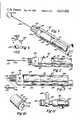
- FIG. 1is a perspective view of an embodiment of my invention
- FIG. 2is a side elevation of the embodiment of my invention
- FIG. 3is a partial side elevation of my invention with the outer housing removed;
- FIG. 4is an end elevation of my invention
- FIG. 5is a side elevation in cross section of my invention taken across lines 5--5 of FIG. 12. disclosing a curved cannula;
- FIG. 6is a sectional side view of the gas dispensing mechanism in a charged condition
- FIG. 7is the same sectional side view of the gas dispensing mechanism in a discharged condition
- FIG. 8is a sectional view of the female reproductive organs prior to the insertion of the cannula into the uterine cavity;
- FIG. 9is a view similar to FIG. 8 with the expanded balloon and cannula inserted into the uterine cavity;
- FIG. 10is a perspective end view of the piston portion of the gas dispensing mechanism
- FIG. 11is a side view of the carbon dioxide charging and discharging device
- FIG. 12is a partial diagramatic end view showing the gas spool valve
- FIG. 13is a partial top plan section showing the spool valve in a gas charging position.
- FIG. 14is a partial top plan section showing the spool valve in a gas discharging position.
- Instrument 20for tubal insufflation of the Fallopian tubes of a female which is operable to transmit a gas into both canals of the Fallopian tubes of the reproductive system of a female.
- Instrument 20has an outer housing 21 that encloses a pump mechanism which has an external plunger handle 22 emerging from the end thereof, the pump being connected to a balloon 23 disposed adjacent the end of a gas dispensing cannula 24. That is, cannula 24 is an elongated flexible probe and is secured to and extends away from the forward end of housing 20 generally along the longitudinal axis of the housing.
- the instrument 20has a check valve 25 secured at the top thereof through which an external gas charging and discharging mechanism 26 may be applied (FIG. 11).
- a spool valve 27is disclosed and is shown in FIG. 13 in a position to receive carbon dioxide under pressure through check valve 25.
- a compression fitting 30is used to help hold cannula 24 and balloon 23 in place within instrument 20.
- housing 20has an inside chamber or cavity 33 that accommodates piston 31 and another internal fitting cylinder assembly 34.
- piston 31slides inside cylinder 33 and cylinder 34 slides insides hollow piston 31.
- the forward end of cylinder 33bears against a fixed transverse wall 35 adjacent the forward end of housing 20.
- Piston 31has a closed forward end 36 that is further defined with a well 37 formed therein.
- the forward facing end of piston 31has an annular outwardly open groove 40 formed therein accommodating a sealing or "O" ring 41 under compression.
- Disposed within piston 31 and secured around well 37is a coiled compression spring 43 that bears against cylinder 34 at the right end portion thereof (FIG. 5).
- "O" ring 41creates a gaseous seal against the inner wall of cylinder 33 when a compressed gas is introduced into an interior cavity or chamber 44 created by the compression of spring 43.
- FIG. 11is directed to the carbon dioxide gas charging mechanism 26 and is designed to accept carbon dioxide capsules 45 that are held in place by housing 46. Upon housing 46 being tightened, it presses the smaller end of capsule 45 into a gas discharge mechanism. The 700 to 900 psi pressure in the capsule is reduced to approximately 10 to 20 psi through the use of a gas valve regulator 47 that discharges the gas through a nozzle 48 that includes an internal check valve.
- FIGS. 5, 13 and 14in which spool valve 27 is disclosed in combination with the other elements through which it works.
- the gas charging and discharging mechanism 26When the gas charging and discharging mechanism 26 is applied to check valve 25, carbon dioxide passes through check valve 25 into a passage 50 which is directly above the spool valve but is shown rotated 90° schematically in FIGS. 13 and 14.
- carbon dioxide reaching passage 50it passes around a reduced diameter concave portion 51 that permits communication with a passageway 52 formed in transverse wall 35.
- the carbon dioxide reaches chamber 44it reacts against compression spring 43 causing piston 31 to move to the right until it reaches the position shown in FIG. 5 where the instrument is fully charged with carbon dioxide.
- a pair of "O" rings 53 and 54are disposed in annular grooves just outside of the annular chamber created by reduced diameter portion 51.
- FIGS. 8 and 9where there is shown a reproductive system of a primate female indicated generally at 60, for receiving the balloon end 23 of cannula 24.
- the reproductive system 60has a uterus 61 joined to a pair of Fallopian tubes 62 and 63, in which the lower part of uterus 61 is integral with a vagina 64.
- Vagina 64has a vaginal cavity 66 and an entrance or vestibule 67, with the opposite end of vaginal cavity 66 being in communication with a cervix 68.
- the cervix 68has a normally closed opening 69 and has a passage from vaginal cavity 66 to the uterine cavity 71.
- the Fallopian tubes 62 and 63have passages which communicate with the uterine cavity 71 and has a top wall or fundus 74 that further includes internal side walls 76 which communicate with cervix 68.
- the uterine cavity 71varies as to size and configuration and is generally flat and somewhat triangular in shape.
- balloon 23has been inserted through cervical opening 69 and is located in uterine cavity 71.
- Balloon 23 and cannula 24may be rotated about the longitudinal axis of cannula 24 during the insertion procedure.
- the cannula 24is partially withdrawn to the general position shown in FIG. 9 where it forms a gaseous seal against inner walls 76 of the uterine cavity 71.
- Balloon 23is constructed such that it is much less resilient and flexible than the balloons of U.S. Pat. No. 4,182,328.
- the function of the present balloonis to provide a pressure seal which prevents air movement through the cervix.
- cannula 24is shown in communication with a pump mechanism 80 that is manually operated through an elongated arm 81 which communicates with element 22.
- Elongated arm 81has an elongated slot 82 formed longitudinally therein that engages a stop member 83 in slot 82, that is anchored to housing 20.
- the length of stroke of plunger 81is controlled through elongated slot 82 and upon push rod 81 being extended internally to its maximum position, a slot 84 formed transversely in the end of push rod 81 may be used to lock the push rod in place.
- cylinder 80 forming a postion of the pumphas a sealing member 85 secured to its end piston member 86 so that upon withdrawal of push rod 81, a vacuum is created in a line 87 leading from cylinder 80 which is in fluid communication with a bore 88 formed in the end of transverse wall 35.
- a collar 90(FIG. 12) is disposed in bore 88 and has a reduced spool diameter 91 formed therein through which a pair of transverse bores 92 and 93 are formed. Also disposed in bore 88 are a pair of "O" rings 94 and 95 that are disposed longitudinally at the innermost end and outermost end of collar 90 where "O" ring 95 is also in communication with a sleeve 96 that also resides in bore 88. Disposed at the outer end of sleeve 96, is a flat circular washer 97 having a central opening therein.
- An elongated longitudinal bore 98lies within cannula 24 and has a side opening 99 that communicates with openings 92 and 93 in spool 90.
- the unique side opening 99 interaction with the double "O" ring sealsprovides a cannula which is easily used.
- the disposable cannulasare merely inserted into compression fittings 30 and collar 90. The fitting 30 is then tightened to create the necessary seals. It will be seen that when plunger 81 is drawn outwardly to the position shown in FIG. 3, a vacuum is created which extends through the longitudinal opening to balloon 23 and thus keeps the balloon in a collapsed state as found in FIG. 8.
- plunger 81Upon being inserted into the uterine cavity, plunger 81 is depressed and locked into position through slot 84 engaging the edge of housing 20 and thus balloon 23 is expanded to the condition shown in FIGS. 1, 5, and 9. Upon a slight withdrawal of cannula 24 and balloon 22, the end of the device will assume the position which is found in FIG. 9.
- the next stepis to discharge the gas into the uterine cavity so that a determination may be made as to the patency of the Fallopian tube canals.
- the spool valveUpon pressing an end cap 100 secured to the end of spool valve 27 by suitable means such as screws, the spool valve is urged until it reaches the condition shown in FIG. 14 wherein an opposite end cap 101 is extended from its position in FIG. 13.
- the spool valve 27Upon spool valve 27 assuming the position of FIG. 14 another spool or reduced diameter portion 102 communicates with passage 55 and 104.
- Portion 102is defined through the use of another "O" ring 103 disposed in an annular groove between "O" ring 57 and valve cap 100.
- the carbon dioxide gas in chamber 44passes through the passageway 55 and communicates with another passageway 104. That is, the carbon dioxide gas is then passed through passageway 104 and further communicates with a central longitudinal passageway 105 formed in cannula 24.
- the emerging orifice 106is formed transversely beyond the end of balloon 23 in cannula 24 so that the opening communicates with fallopian tubes 62 and 63 in the uterine cavity 71. In some sitautions it may also be desirable to curve the end of cannula 24. It will be further noted that when spool valve 27 is in the position shown in FIG.
- the amount of carbon dioxide escaping into the uterine cavitymay be measured and upon measuring the amount of carbon dioxide that escapes into the peritoneal cavity, a determination may then be made as to whether or not the fallopian tube are "Open”, partially occluded or completed "Closed.”
- the discharged instrument 20is fitted with a new cannula 24.
- Gas charge mechanism 26complete with capsule 45, is fitted to check valve 25 until the device is fully charged. Any attempt to recharge the device will cause the spring to compress until "O" ring 41 no longer seals and overpressure is released.
- the deviceautomatically works like a pressure relief valve insuring that the pressure of gas applied through the instrument is never greater than the designed pressure.
- the springcounteracts against gas within chamber 44. Since aging springs only weaken, the construction insures that the pressure delivered by the device will never increase due to a component failure.
- Balloon 23is evacuated by withdrawing piston 86 and plunger 22 as shown in FIG. 3. The instrument is then inserted toward the uterine cavity as shown in FIGS. 8 and 9 until the balloon portion is situated within the cervix. Balloon 23 is then expanded by depressing and locking piston 22. Markings on the shaft of cannula 24 assist in determining proper placement of the balloon.
- the balloonOnce inflated, the balloon seals the uterine cavity from the vaginal cavity. The seal is effective up to a pressure of about 250 mm Hg. The relatively thick, rigid balloon deforms the walls of the cervix in forming the seal.
- the balloonis not capable of expanding toward fundus 74 or over opening 106. It is constructed and arranged to exert a sealing pressure against the cervix rather than to be a deformable balloon which would squeeze into the uterine cavity when filled with sufficient gas.
- Spool valve 27is moved to the test position by depressing end cap 100. Approximately 55 cubic centimeters of carbon dioxide are available to be introduced into the uterine cavity at a pressure of about 200 mm Hg. through openings 106. As the gas enters the uterine cavity, the volume within chamber 44 decreases, and spring 43 rebounds in an effort to keep a constant pressure of about 200 mm Hg.
- the device of the inventionmeasures by a volumetric change. Equal pressure is maintained within the instrument and uterine cavity as long as gas is remaining within chamber 44. This overcomes some of the disadvantages inherent in devices which rely on pressure changes. Those devices may provide misleading results if a slow leak is present. In such cases, the relatively resilient uterine walls contract as volume is lost, with little apparent pressure drop. In contrast, the device of the invention maintains the same pressurized distention of the uterine walls during the test and any change is always seen as loss of gas volume.
- plunger handle 22Upon the test being completed, plunger handle 22 is withdrawn from the instrument, collapsing balloon 23 and permitting the balloon 23 and cannula 24 to be withdrawn from the uterine cavity. It will also be observed that various steps for carrying out the procedural method of determining the patency of the fallopian tubes is established.
Landscapes
- Health & Medical Sciences (AREA)
- Life Sciences & Earth Sciences (AREA)
- Heart & Thoracic Surgery (AREA)
- Animal Behavior & Ethology (AREA)
- Veterinary Medicine (AREA)
- Public Health (AREA)
- General Health & Medical Sciences (AREA)
- Engineering & Computer Science (AREA)
- Biomedical Technology (AREA)
- Surgery (AREA)
- Hematology (AREA)
- Anesthesiology (AREA)
- Pulmonology (AREA)
- Biophysics (AREA)
- Child & Adolescent Psychology (AREA)
- Reproductive Health (AREA)
- Pregnancy & Childbirth (AREA)
- Nuclear Medicine, Radiotherapy & Molecular Imaging (AREA)
- Gynecology & Obstetrics (AREA)
- Medical Informatics (AREA)
- Molecular Biology (AREA)
- Epidemiology (AREA)
- Pain & Pain Management (AREA)
- Physical Education & Sports Medicine (AREA)
- Rehabilitation Therapy (AREA)
- Measuring And Recording Apparatus For Diagnosis (AREA)
- Endoscopes (AREA)
Abstract
Description
Claims (12)
Priority Applications (1)
| Application Number | Priority Date | Filing Date | Title |
|---|---|---|---|
| US06/752,132US4611602A (en) | 1984-07-19 | 1985-07-05 | Instrument and method of tubal insufflation |
Applications Claiming Priority (2)
| Application Number | Priority Date | Filing Date | Title |
|---|---|---|---|
| US63241784A | 1984-07-19 | 1984-07-19 | |
| US06/752,132US4611602A (en) | 1984-07-19 | 1985-07-05 | Instrument and method of tubal insufflation |
Related Parent Applications (1)
| Application Number | Title | Priority Date | Filing Date |
|---|---|---|---|
| US63241784AContinuation-In-Part | 1984-07-19 | 1984-07-19 |
Publications (1)
| Publication Number | Publication Date |
|---|---|
| US4611602Atrue US4611602A (en) | 1986-09-16 |
Family
ID=27091624
Family Applications (1)
| Application Number | Title | Priority Date | Filing Date |
|---|---|---|---|
| US06/752,132Expired - Fee RelatedUS4611602A (en) | 1984-07-19 | 1985-07-05 | Instrument and method of tubal insufflation |
Country Status (1)
| Country | Link |
|---|---|
| US (1) | US4611602A (en) |
Cited By (22)
| Publication number | Priority date | Publication date | Assignee | Title |
|---|---|---|---|---|
| US5377688A (en)* | 1993-04-16 | 1995-01-03 | The Trustees Of Columbia University In The City Of New York | Apparatus and method to objectively measure sensory discrimination thresholds in the upper aero digestive tract |
| US5515860A (en)* | 1993-04-16 | 1996-05-14 | The Trustees Of Columbia University In The City Of New York | Apparatus and method to objectively measure sensory discrimination thresholds in the upper aero digestive tract |
| US6036655A (en)* | 1993-04-16 | 2000-03-14 | The Trustees Of Columbia University In The City Of New York | Apparatus and method to objectively measure sensory discrimination thresholds in the upper aero digestive tract |
| US6355003B1 (en)* | 1993-04-16 | 2002-03-12 | The Trustees Of Columbia University In The City Of New York | Apparatus and method to objectively measure sensory discrimination thresholds in the upper aero digestive tract |
| US6554780B1 (en)* | 1999-11-10 | 2003-04-29 | Novacept | System and method for detecting perforations in a body cavity |
| US6939336B2 (en) | 2000-08-16 | 2005-09-06 | Violetta Silfver | Method and device for treating inter alia the cervix |
| US20050240211A1 (en)* | 2004-04-21 | 2005-10-27 | Stefan Sporri | Apparatus and method for selectably treating a fallopian tube |
| US20060253039A1 (en)* | 2005-05-05 | 2006-11-09 | Mckenna Robert H | Anastomotic ring applier with inflatable members |
| US20080167664A1 (en)* | 2006-12-12 | 2008-07-10 | Cytyc Corporation | Method and apparatus for verifying occlusion of fallopian tubes |
| US20090082622A1 (en)* | 2007-09-26 | 2009-03-26 | Satoshi Takekoshi | Placement method and placement system |
| WO2011100187A1 (en)* | 2010-02-11 | 2011-08-18 | Hollister Incorporated | Inflation cuff with transient-resistant over-pressure preventor |
| US8048101B2 (en) | 2004-02-25 | 2011-11-01 | Femasys Inc. | Methods and devices for conduit occlusion |
| US8048086B2 (en) | 2004-02-25 | 2011-11-01 | Femasys Inc. | Methods and devices for conduit occlusion |
| US8052669B2 (en) | 2004-02-25 | 2011-11-08 | Femasys Inc. | Methods and devices for delivery of compositions to conduits |
| WO2012106474A3 (en)* | 2011-02-04 | 2012-12-13 | Minerva Surgical, Inc. | Methods and systems for evaluating the integrity of a uterine cavity |
| US9238127B2 (en) | 2004-02-25 | 2016-01-19 | Femasys Inc. | Methods and devices for delivering to conduit |
| US20160116365A1 (en)* | 2013-05-07 | 2016-04-28 | Luedolph Management GmbH | Leak test arrangement and leak test method |
| US9554826B2 (en) | 2008-10-03 | 2017-01-31 | Femasys, Inc. | Contrast agent injection system for sonographic imaging |
| US10070888B2 (en) | 2008-10-03 | 2018-09-11 | Femasys, Inc. | Methods and devices for sonographic imaging |
| US20190240466A1 (en)* | 2008-03-31 | 2019-08-08 | Dobrivoje Rajkovic | Disposable Gynecologic Instrument For Dilation Of Body Cavities By Fluid Injection |
| EP3787533A4 (en)* | 2018-05-02 | 2022-06-01 | Femasys, Inc. | CONTROLLED DELIVERY METHODS AND DEVICES |
| US12171463B2 (en) | 2008-10-03 | 2024-12-24 | Femasys Inc. | Contrast agent generation and injection system for sonographic imaging |
Citations (1)
| Publication number | Priority date | Publication date | Assignee | Title |
|---|---|---|---|---|
| US2441237A (en)* | 1946-12-28 | 1948-05-11 | Davies Charles | Tubal insufflator |
- 1985
- 1985-07-05USUS06/752,132patent/US4611602A/ennot_activeExpired - Fee Related
Patent Citations (1)
| Publication number | Priority date | Publication date | Assignee | Title |
|---|---|---|---|---|
| US2441237A (en)* | 1946-12-28 | 1948-05-11 | Davies Charles | Tubal insufflator |
Cited By (60)
| Publication number | Priority date | Publication date | Assignee | Title |
|---|---|---|---|---|
| US5515860A (en)* | 1993-04-16 | 1996-05-14 | The Trustees Of Columbia University In The City Of New York | Apparatus and method to objectively measure sensory discrimination thresholds in the upper aero digestive tract |
| US6036655A (en)* | 1993-04-16 | 2000-03-14 | The Trustees Of Columbia University In The City Of New York | Apparatus and method to objectively measure sensory discrimination thresholds in the upper aero digestive tract |
| US6355003B1 (en)* | 1993-04-16 | 2002-03-12 | The Trustees Of Columbia University In The City Of New York | Apparatus and method to objectively measure sensory discrimination thresholds in the upper aero digestive tract |
| US5377688A (en)* | 1993-04-16 | 1995-01-03 | The Trustees Of Columbia University In The City Of New York | Apparatus and method to objectively measure sensory discrimination thresholds in the upper aero digestive tract |
| US7063670B2 (en) | 1999-11-10 | 2006-06-20 | Cytyc Surgical Products | System and method for detecting perforations in a body cavity |
| US6554780B1 (en)* | 1999-11-10 | 2003-04-29 | Novacept | System and method for detecting perforations in a body cavity |
| US6743184B2 (en) | 1999-11-10 | 2004-06-01 | Novacept | System and method for detecting perforations in a body cavity |
| US6872183B2 (en) | 1999-11-10 | 2005-03-29 | Cytyc Surgical Product | System and method for detecting perforations in a body cavity |
| US6939336B2 (en) | 2000-08-16 | 2005-09-06 | Violetta Silfver | Method and device for treating inter alia the cervix |
| US9238127B2 (en) | 2004-02-25 | 2016-01-19 | Femasys Inc. | Methods and devices for delivering to conduit |
| US8316853B2 (en) | 2004-02-25 | 2012-11-27 | Femasys Inc. | Method and devices for conduit occlusion |
| US9839444B2 (en) | 2004-02-25 | 2017-12-12 | Femasys Inc. | Methods and devices for conduit occlusion |
| US9308023B2 (en) | 2004-02-25 | 2016-04-12 | Femasys Inc. | Methods and devices for conduit occlusion |
| US9220880B2 (en) | 2004-02-25 | 2015-12-29 | Femasys Inc. | Methods and devices for delivery of compositions to conduits |
| US11779372B2 (en) | 2004-02-25 | 2023-10-10 | Femasys Inc. | Methods and devices for conduit occlusion |
| US8048101B2 (en) | 2004-02-25 | 2011-11-01 | Femasys Inc. | Methods and devices for conduit occlusion |
| US8048086B2 (en) | 2004-02-25 | 2011-11-01 | Femasys Inc. | Methods and devices for conduit occlusion |
| US8052669B2 (en) | 2004-02-25 | 2011-11-08 | Femasys Inc. | Methods and devices for delivery of compositions to conduits |
| US10111687B2 (en) | 2004-02-25 | 2018-10-30 | Femasys, Inc. | Methods and devices for conduit occlusion |
| US8316854B2 (en) | 2004-02-25 | 2012-11-27 | Femasys Inc. | Methods and devices for conduit occlusion |
| US9402762B2 (en) | 2004-02-25 | 2016-08-02 | Femasys Inc. | Methods and devices for conduit occlusion |
| US8324193B2 (en) | 2004-02-25 | 2012-12-04 | Femasys Inc. | Methods and devices for delivery of compositions to conduits |
| US9034053B2 (en) | 2004-02-25 | 2015-05-19 | Femasys Inc. | Methods and devices for conduit occlusion |
| US8336552B2 (en) | 2004-02-25 | 2012-12-25 | Femasys Inc. | Methods and devices for conduit occlusion |
| US10292732B2 (en) | 2004-02-25 | 2019-05-21 | Femasys, Inc. | Methods and devices for conduit occlusion |
| US8695606B2 (en) | 2004-02-25 | 2014-04-15 | Femasys Inc. | Methods and devices for conduit occlusion |
| US8726906B2 (en) | 2004-02-25 | 2014-05-20 | Femasys Inc. | Methods and devices for conduit occlusion |
| US20050240211A1 (en)* | 2004-04-21 | 2005-10-27 | Stefan Sporri | Apparatus and method for selectably treating a fallopian tube |
| US20060253039A1 (en)* | 2005-05-05 | 2006-11-09 | Mckenna Robert H | Anastomotic ring applier with inflatable members |
| US7645288B2 (en) | 2005-05-05 | 2010-01-12 | Ethicon Endo-Surgery, Inc. | Anastomotic ring applier with inflatable members |
| US20080167664A1 (en)* | 2006-12-12 | 2008-07-10 | Cytyc Corporation | Method and apparatus for verifying occlusion of fallopian tubes |
| US8181657B2 (en)* | 2007-09-26 | 2012-05-22 | Olympus Medical Systems Corp. | Placement method and placement system |
| US20090082622A1 (en)* | 2007-09-26 | 2009-03-26 | Satoshi Takekoshi | Placement method and placement system |
| US11020574B2 (en)* | 2008-03-31 | 2021-06-01 | Inove Doo Beograd | Disposable gynecologic instrument for dilation of body cavities by fluid injection |
| US20190240466A1 (en)* | 2008-03-31 | 2019-08-08 | Dobrivoje Rajkovic | Disposable Gynecologic Instrument For Dilation Of Body Cavities By Fluid Injection |
| US9554826B2 (en) | 2008-10-03 | 2017-01-31 | Femasys, Inc. | Contrast agent injection system for sonographic imaging |
| US12426923B2 (en) | 2008-10-03 | 2025-09-30 | Femasys Inc. | Methods and devices for sonographic imaging |
| US12171463B2 (en) | 2008-10-03 | 2024-12-24 | Femasys Inc. | Contrast agent generation and injection system for sonographic imaging |
| US11980395B2 (en) | 2008-10-03 | 2024-05-14 | Femasys Inc. | Methods and devices for sonographic imaging |
| US10070888B2 (en) | 2008-10-03 | 2018-09-11 | Femasys, Inc. | Methods and devices for sonographic imaging |
| US11648033B2 (en) | 2008-10-03 | 2023-05-16 | Femasys Inc. | Methods and devices for sonographic imaging |
| US10172643B2 (en) | 2008-10-03 | 2019-01-08 | Femasys, Inc. | Contrast agent generation and injection system for sonographic imaging |
| US10258375B2 (en) | 2008-10-03 | 2019-04-16 | Femasys, Inc. | Methods and devices for sonographic imaging |
| US11154326B2 (en) | 2008-10-03 | 2021-10-26 | Femasys Inc. | Methods and devices for sonographic imaging |
| WO2011100187A1 (en)* | 2010-02-11 | 2011-08-18 | Hollister Incorporated | Inflation cuff with transient-resistant over-pressure preventor |
| US9162042B2 (en) | 2010-02-11 | 2015-10-20 | Hollister Incorporated | Inflation cuff with transient-resistant over-pressure preventor |
| US10932712B2 (en) | 2011-02-04 | 2021-03-02 | Minerva Surgical, Inc. | Methods and systems for evaluating the integrity of a uterine cavity |
| US20170215788A1 (en)* | 2011-02-04 | 2017-08-03 | Minerva Surgical, Inc. | Methods and systems for evaluating the integrity of a uterine cavity |
| US20130158428A1 (en)* | 2011-02-04 | 2013-06-20 | Minerva Surgical, Inc. | Methods and systems for evaluating the integrity of a uterine cavity |
| US9655557B2 (en)* | 2011-02-04 | 2017-05-23 | Minerva Surgical, Inc. | Methods and systems for evaluating the integrity of a uterine cavity |
| WO2012106474A3 (en)* | 2011-02-04 | 2012-12-13 | Minerva Surgical, Inc. | Methods and systems for evaluating the integrity of a uterine cavity |
| US12274557B2 (en) | 2011-02-04 | 2025-04-15 | Minerva Surgical, Inc. | Methods and systems for evaluating the integrity of a uterine cavity |
| US10028696B2 (en)* | 2011-02-04 | 2018-07-24 | Minerva Surgical, Inc. | Methods and systems for evaluating the integrity of a uterine cavity |
| US11903722B2 (en) | 2011-02-04 | 2024-02-20 | Minerva Surgical, Inc. | Methods and systems for evaluating the integrity of a uterine cavity |
| US10073001B2 (en)* | 2013-05-07 | 2018-09-11 | Luedolph Management GmbH | Leak test arrangement and leak test method |
| US20160116365A1 (en)* | 2013-05-07 | 2016-04-28 | Luedolph Management GmbH | Leak test arrangement and leak test method |
| EP4385529A3 (en)* | 2018-05-02 | 2024-09-18 | Femasys, Inc. | Devices for controlled delivery |
| US12127968B2 (en) | 2018-05-02 | 2024-10-29 | Femasys Inc. | Methods and devices for controlled delivery |
| US11744729B2 (en) | 2018-05-02 | 2023-09-05 | Femasys Inc. | Methods and devices for controlled delivery |
| EP3787533A4 (en)* | 2018-05-02 | 2022-06-01 | Femasys, Inc. | CONTROLLED DELIVERY METHODS AND DEVICES |
Similar Documents
| Publication | Publication Date | Title |
|---|---|---|
| US4611602A (en) | Instrument and method of tubal insufflation | |
| US4089337A (en) | Uterine catheter and manipulator with inflatable seal | |
| US4182328A (en) | Dispensing instrument and method | |
| US4439185A (en) | Inflating and deflating device for vascular dilating catheter assembly | |
| US4207891A (en) | Dispensing instrument with supported balloon | |
| US3875939A (en) | Single stroke dispensing method | |
| CA1193929A (en) | Combined uterine injector and manipulative device | |
| USRE29207E (en) | Dispensing method and apparatus | |
| US3850176A (en) | Nasal tampon | |
| US4526196A (en) | Gas pressure measuring and regulating device and method | |
| US4160446A (en) | Apparatus for and method of sterilization by the delivery of tubal-occluding polymer | |
| US3822702A (en) | Dispensing method and apparatus | |
| US3190291A (en) | Self-inflating bag catheter | |
| EP0248759B1 (en) | Dilatation catheter and constant pressure syringe | |
| US20140052063A1 (en) | Apparatus for preventing over inflation of the retention balloon in medical catheters and airway devices | |
| US20080077054A1 (en) | Cervical dilator and methods of use | |
| JPH0352302B2 (en) | ||
| FI62768C (en) | INSTRUMENT FOER INFOERING AV ETT PREPARAT I AEGGLEDARKANALERNA | |
| EP0366292B1 (en) | Single channel balloon uterine injector | |
| JP3021574B2 (en) | Uterus access device | |
| US2839050A (en) | Device for measuring the tonus of the muscular system of the floor of the vagina, pelvis and adjacent areas | |
| US20130245664A1 (en) | Cervical dilator | |
| US20040127931A1 (en) | Cervical dilator | |
| EP3038692A1 (en) | Cervical dilator | |
| US3152592A (en) | Self-inflating bag catheter |
Legal Events
| Date | Code | Title | Description |
|---|---|---|---|
| AS | Assignment | Owner name:BIONEXUS, INC., 5257 NORTH BOULEVARD RALEIGH, NC Free format text:ASSIGNMENT OF ASSIGNORS INTEREST.;ASSIGNOR:BOLDUC, LEE R.;REEL/FRAME:004434/0149 Effective date:19850703 | |
| AS | Assignment | Owner name:DUNCAN, CLAYTON I., 616 MILOWE ROAD, RALEIGH, NC Free format text:MORTGAGE;ASSIGNOR:BIONEXUS, INC., A MN CORP;REEL/FRAME:004608/0919 Effective date:19860925 Owner name:PIROTTE, JOHN K., 14240 WYNDFIELD CIRCLE, RALEIGH, Free format text:MORTGAGE;ASSIGNOR:BIONEXUS, INC., A MN CORP;REEL/FRAME:004608/0919 Effective date:19860925 Owner name:EDWARDS, LUCILLE L., ROUTE 10, BOX 245, CHAPEL HIL Free format text:MORTGAGE;ASSIGNOR:BIONEXUS, INC., A MN CORP;REEL/FRAME:004608/0919 Effective date:19860925 Owner name:WOODY, W. RUFFIN, JR., P.O. BOX 381, ROXBORO, NC Free format text:MORTGAGE;ASSIGNOR:BIONEXUS, INC., A MN CORP;REEL/FRAME:004608/0919 Effective date:19860925 | |
| AS | Assignment | Owner name:PDEW, INC., 4700 HOMEWOOD COURT, SUITE 340, RALEIG Free format text:ASSIGNMENT OF ASSIGNORS INTEREST.;ASSIGNORS:PIROTTE, JOHN, K.,;EDWARDS, LUCILLE L.;WOODY, W., RUFFIN, JR.,;AND OTHERS;REEL/FRAME:004828/0004;SIGNING DATES FROM 19870928 TO 19871216 Owner name:CRX MEDICAL, INC., 5265 NORTH BOULEVARD, RALEIGH, Free format text:ASSIGNMENT OF ASSIGNORS INTEREST.;ASSIGNORS:PIROTTE, JOHN, K.;EDWARDS, LUCILLE;WOODY, W., RUFFIN, JR.;AND OTHERS;REEL/FRAME:004831/0256;SIGNING DATES FROM 19870928 TO 19871210 Owner name:PDEW, INC., A CORP. OF NORTH CAROLINA,NORTH CARO Free format text:ASSIGNMENT OF ASSIGNORS INTEREST;ASSIGNORS:PIROTTE, JOHN, K.,;EDWARDS, LUCILLE L.;WOODY, W., RUFFIN, JR.,;AND OTHERS;SIGNING DATES FROM 19870928 TO 19871216;REEL/FRAME:004828/0004 Owner name:CRX MEDICAL, INC., NORTH A CORP. OF NC.,NEW YORK Free format text:ASSIGNMENT OF ASSIGNORS INTEREST;ASSIGNORS:PIROTTE, JOHN, K.;EDWARDS, LUCILLE;WOODY, W., RUFFIN, JR.;AND OTHERS;SIGNING DATES FROM 19870928 TO 19871210;REEL/FRAME:004831/0256 | |
| FEPP | Fee payment procedure | Free format text:PAYOR NUMBER ASSIGNED (ORIGINAL EVENT CODE: ASPN); ENTITY STATUS OF PATENT OWNER: SMALL ENTITY Free format text:PAT HOLDER CLAIMS SMALL ENTITY STATUS - SMALL BUSINESS (ORIGINAL EVENT CODE: SM02); ENTITY STATUS OF PATENT OWNER: SMALL ENTITY | |
| FPAY | Fee payment | Year of fee payment:4 | |
| REMI | Maintenance fee reminder mailed | ||
| LAPS | Lapse for failure to pay maintenance fees | ||
| FP | Lapsed due to failure to pay maintenance fee | Effective date:19940921 | |
| STCH | Information on status: patent discontinuation | Free format text:PATENT EXPIRED DUE TO NONPAYMENT OF MAINTENANCE FEES UNDER 37 CFR 1.362 |