US4611377A - Interchangeable robot end-of-arm tooling system - Google Patents
Interchangeable robot end-of-arm tooling systemDownload PDFInfo
- Publication number
- US4611377A US4611377AUS06/616,974US61697484AUS4611377AUS 4611377 AUS4611377 AUS 4611377AUS 61697484 AUS61697484 AUS 61697484AUS 4611377 AUS4611377 AUS 4611377A
- Authority
- US
- United States
- Prior art keywords
- tool
- tools
- robot
- adapter
- drill
- Prior art date
- Legal status (The legal status is an assumption and is not a legal conclusion. Google has not performed a legal analysis and makes no representation as to the accuracy of the status listed.)
- Expired - Lifetime
Links
Images


Classifications
- B—PERFORMING OPERATIONS; TRANSPORTING
- B23—MACHINE TOOLS; METAL-WORKING NOT OTHERWISE PROVIDED FOR
- B23Q—DETAILS, COMPONENTS, OR ACCESSORIES FOR MACHINE TOOLS, e.g. ARRANGEMENTS FOR COPYING OR CONTROLLING; MACHINE TOOLS IN GENERAL CHARACTERISED BY THE CONSTRUCTION OF PARTICULAR DETAILS OR COMPONENTS; COMBINATIONS OR ASSOCIATIONS OF METAL-WORKING MACHINES, NOT DIRECTED TO A PARTICULAR RESULT
- B23Q7/00—Arrangements for handling work specially combined with or arranged in, or specially adapted for use in connection with, machine tools, e.g. for conveying, loading, positioning, discharging, sorting
- B23Q7/04—Arrangements for handling work specially combined with or arranged in, or specially adapted for use in connection with, machine tools, e.g. for conveying, loading, positioning, discharging, sorting by means of grippers
- B23Q7/043—Construction of the grippers
- B—PERFORMING OPERATIONS; TRANSPORTING
- B23—MACHINE TOOLS; METAL-WORKING NOT OTHERWISE PROVIDED FOR
- B23Q—DETAILS, COMPONENTS, OR ACCESSORIES FOR MACHINE TOOLS, e.g. ARRANGEMENTS FOR COPYING OR CONTROLLING; MACHINE TOOLS IN GENERAL CHARACTERISED BY THE CONSTRUCTION OF PARTICULAR DETAILS OR COMPONENTS; COMBINATIONS OR ASSOCIATIONS OF METAL-WORKING MACHINES, NOT DIRECTED TO A PARTICULAR RESULT
- B23Q3/00—Devices holding, supporting, or positioning work or tools, of a kind normally removable from the machine
- B23Q3/155—Arrangements for automatic insertion or removal of tools, e.g. combined with manual handling
- B23Q3/1552—Arrangements for automatic insertion or removal of tools, e.g. combined with manual handling parts of devices for automatically inserting or removing tools
- B23Q3/15553—Tensioning devices or tool holders, e.g. grippers
- B—PERFORMING OPERATIONS; TRANSPORTING
- B23—MACHINE TOOLS; METAL-WORKING NOT OTHERWISE PROVIDED FOR
- B23Q—DETAILS, COMPONENTS, OR ACCESSORIES FOR MACHINE TOOLS, e.g. ARRANGEMENTS FOR COPYING OR CONTROLLING; MACHINE TOOLS IN GENERAL CHARACTERISED BY THE CONSTRUCTION OF PARTICULAR DETAILS OR COMPONENTS; COMBINATIONS OR ASSOCIATIONS OF METAL-WORKING MACHINES, NOT DIRECTED TO A PARTICULAR RESULT
- B23Q7/00—Arrangements for handling work specially combined with or arranged in, or specially adapted for use in connection with, machine tools, e.g. for conveying, loading, positioning, discharging, sorting
- B23Q7/04—Arrangements for handling work specially combined with or arranged in, or specially adapted for use in connection with, machine tools, e.g. for conveying, loading, positioning, discharging, sorting by means of grippers
- B23Q7/046—Handling workpieces or tools
- B—PERFORMING OPERATIONS; TRANSPORTING
- B25—HAND TOOLS; PORTABLE POWER-DRIVEN TOOLS; MANIPULATORS
- B25J—MANIPULATORS; CHAMBERS PROVIDED WITH MANIPULATION DEVICES
- B25J13/00—Controls for manipulators
- B25J13/08—Controls for manipulators by means of sensing devices, e.g. viewing or touching devices
- B25J13/081—Touching devices, e.g. pressure-sensitive
- B25J13/082—Grasping-force detectors
- B—PERFORMING OPERATIONS; TRANSPORTING
- B25—HAND TOOLS; PORTABLE POWER-DRIVEN TOOLS; MANIPULATORS
- B25J—MANIPULATORS; CHAMBERS PROVIDED WITH MANIPULATION DEVICES
- B25J15/00—Gripping heads and other end effectors
- B25J15/02—Gripping heads and other end effectors servo-actuated
- B25J15/0253—Gripping heads and other end effectors servo-actuated comprising parallel grippers
- B—PERFORMING OPERATIONS; TRANSPORTING
- B25—HAND TOOLS; PORTABLE POWER-DRIVEN TOOLS; MANIPULATORS
- B25J—MANIPULATORS; CHAMBERS PROVIDED WITH MANIPULATION DEVICES
- B25J15/00—Gripping heads and other end effectors
- B25J15/04—Gripping heads and other end effectors with provision for the remote detachment or exchange of the head or parts thereof
- B25J15/0491—Gripping heads and other end effectors with provision for the remote detachment or exchange of the head or parts thereof comprising end-effector racks
- G—PHYSICS
- G05—CONTROLLING; REGULATING
- G05B—CONTROL OR REGULATING SYSTEMS IN GENERAL; FUNCTIONAL ELEMENTS OF SUCH SYSTEMS; MONITORING OR TESTING ARRANGEMENTS FOR SUCH SYSTEMS OR ELEMENTS
- G05B19/00—Programme-control systems
- G05B19/02—Programme-control systems electric
- G05B19/418—Total factory control, i.e. centrally controlling a plurality of machines, e.g. direct or distributed numerical control [DNC], flexible manufacturing systems [FMS], integrated manufacturing systems [IMS] or computer integrated manufacturing [CIM]
- G05B19/41815—Total factory control, i.e. centrally controlling a plurality of machines, e.g. direct or distributed numerical control [DNC], flexible manufacturing systems [FMS], integrated manufacturing systems [IMS] or computer integrated manufacturing [CIM] characterised by the cooperation between machine tools, manipulators and conveyor or other workpiece supply system, workcell
- G05B19/41825—Total factory control, i.e. centrally controlling a plurality of machines, e.g. direct or distributed numerical control [DNC], flexible manufacturing systems [FMS], integrated manufacturing systems [IMS] or computer integrated manufacturing [CIM] characterised by the cooperation between machine tools, manipulators and conveyor or other workpiece supply system, workcell machine tools and manipulators only, machining centre
- G—PHYSICS
- G05—CONTROLLING; REGULATING
- G05B—CONTROL OR REGULATING SYSTEMS IN GENERAL; FUNCTIONAL ELEMENTS OF SUCH SYSTEMS; MONITORING OR TESTING ARRANGEMENTS FOR SUCH SYSTEMS OR ELEMENTS
- G05B2219/00—Program-control systems
- G05B2219/30—Nc systems
- G05B2219/39—Robotics, robotics to robotics hand
- G05B2219/39468—Changeable hand, tool, code carrier, detector
- Y—GENERAL TAGGING OF NEW TECHNOLOGICAL DEVELOPMENTS; GENERAL TAGGING OF CROSS-SECTIONAL TECHNOLOGIES SPANNING OVER SEVERAL SECTIONS OF THE IPC; TECHNICAL SUBJECTS COVERED BY FORMER USPC CROSS-REFERENCE ART COLLECTIONS [XRACs] AND DIGESTS
- Y02—TECHNOLOGIES OR APPLICATIONS FOR MITIGATION OR ADAPTATION AGAINST CLIMATE CHANGE
- Y02P—CLIMATE CHANGE MITIGATION TECHNOLOGIES IN THE PRODUCTION OR PROCESSING OF GOODS
- Y02P90/00—Enabling technologies with a potential contribution to greenhouse gas [GHG] emissions mitigation
- Y02P90/02—Total factory control, e.g. smart factories, flexible manufacturing systems [FMS] or integrated manufacturing systems [IMS]
- Y—GENERAL TAGGING OF NEW TECHNOLOGICAL DEVELOPMENTS; GENERAL TAGGING OF CROSS-SECTIONAL TECHNOLOGIES SPANNING OVER SEVERAL SECTIONS OF THE IPC; TECHNICAL SUBJECTS COVERED BY FORMER USPC CROSS-REFERENCE ART COLLECTIONS [XRACs] AND DIGESTS
- Y10—TECHNICAL SUBJECTS COVERED BY FORMER USPC
- Y10T—TECHNICAL SUBJECTS COVERED BY FORMER US CLASSIFICATION
- Y10T29/00—Metal working
- Y10T29/49—Method of mechanical manufacture
- Y10T29/49764—Method of mechanical manufacture with testing or indicating
- Y10T29/49771—Quantitative measuring or gauging
Definitions
- This inventionrelates to robotic tooling systems, and more particularly to an end-of-arm tooling system having interchangeable tools and operating under computer control.
- the present inventionis an interchangeable robot end-of-arm tooling system that allows a variety of intelligent tools to be picked up and replaced by a single robot arm and to be operated under independent computer control.
- This systemcombines computer sophistication with interchangeability to allow the end user to apply robotics in more applications.
- the tooling systemincludes a quick change adapter mounted to the robot arm that picks up and replaces any one of a family of manufacturing and assembly tools.
- This system of toolsis intelligent in that an independent computer controller (“preprocessor") provides closed-loop control of the end-of-arm tooling in addition to giving the operator real time feedback as to the performance of the tool.
- preprocessorindependent computer controller
- diagnostic softwareembodied in the overall software system allows all segments of the tooling system to be continuously monitored.
- a manual mode of operationis provided to allow the user to control individual steps of operation.
- FIG. 1is schematic representation of the environment of the invention
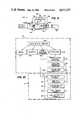
- FIG. 2is a schematic block diagram of the invention
- FIG. 3is a partially broken away side view of a quick change adapter for use in connection with the present invention
- FIG. 4is an end view of the quick change adapter of FIG. 3;
- FIG. 5is a partially broken away side view of a drill for use in connection with the present invention.
- FIG. 6is a side view of a gripper for use in connection with the present invention.
- FIG. 7is a partially broken away side view of the gripper of FIG. 6;
- FIG. 8is a partially broken away side view of a gripper for use in connection with the present invention.
- FIG. 9is a partially broken-away side view of a nutrunner for use in connection with the present invention.
- FIG. 10is a flow chart of software adapted for use in connection with the present invention.
- the present inventionis illustrated in the environment of a factory where complex parts, such as engine block 10, are manufactured.
- Engine block 10is fixed with respect to the factory floor by fixture 12.
- the interchangeable robot end-of-arm tooling system illustrated in FIG. 1is adapted for use with a commercially available robot arm 14.
- robot arm 14could be a Model 776 manufactured by Cincinnati-Milacron of Cincinnati, Ohio.
- Robot arm 14includes a robot controller 16.
- Robot controller 16includes a computerized controller, but the lack in power and sophistication of the standard robot controller supplied with available robot arms precludes all uses of the robot arms other than simple positioning of the end of the arm with dedicated tooling.
- the tooling system of the present inventionincludes a preprocessor 18, which is a computer controller specifically adapted for use with the tooling system.
- Preprocessor 18is connected to the robot controller by means of cable 20.
- a terminal 22, with keyboard and display,is connected to the preprocessor 18 by cable 24.
- Quick change adapter 26is permanently attached to the end of robot arm 14.
- Tool 28is shown attached to the quick change adapter, and in the situation illustrated in FIG. 1, tool 28 is a drill having drill bit 30 positioned to drill a hole in engine block 10.
- a group of cables and hosesgenerally indicated by reference numeral 32, connects quick change adapter 26 to robot controller 16, and supply the quick change adapter 26 with electrical power, compressed air, coolant, and data communications to and from the rest of the system.
- Table 34holds additional tools 36, which, by way of example, could include grippers, nutrunners, or other tools.
- the essential object of this inventionis to enable robot arm 14 to interchange between tools of 28, 36, 38 and 40 and perform tasks using these tools, all by computer control provided by preprocessor 18.
- the systemincludes preprocessor 18, with associated terminal 22, quick change adapter 26, and a number of tools, such as drill 28 and tools 36, 38 and 40.
- preprocessor 18includes CPU board 50, which in the preferred embodiment is a self-contained board designated by model number 3830 and manufactured by ISI Inc. of Sunnyvale Calif.
- CPU board 50is connected to various input/output boards and memory boards.
- Serial I/O board 52is connected to terminal 22 by cable 24.
- serial I/O board 52is a model number 3711 board manufactured by ISI, Inc.
- Preprocessor 18includes RAM 54 and ROM 56.
- the RAMis provided on a model number 3220-1 board manufactured by ISI, Inc.
- the ROMis provided on two model number 7705 boards manufactured by Prolog Corporation of Monterey, Calif. These cards provide 16K bytes of RAM and 128K bytes of ROM.
- Preprocessor 18communicates with the rest of the system through a bank of discrete I/O solid state relays 60.
- relay bank 60comprises four model number PB-24 relay boards manufactured by Opto 22 of Huntington Beach, Calif.
- Relay bank 60is connected to pneumatic interface 58 by means of cable 62.
- the status of the I/O relays in bank 60is read by discrete I/O interface board 64 connected to CPU board 50.
- discrete I/O interface board 64is a model number 7507 board manufactured by Prolog Corp. Certain of the tools in the systems generate analog measurement signals.
- Amplifier 66is used to amplify strain gage type signals, and the preferred embodiment is a model number 3170 board manufactured by Daytronic of Miamisburg, Ohio.
- Piezoelectric signal conditioner 68is provided to analyze signals from these transducers, and in the preferred embodiment, is manufactured by PCB Piezotronics, Inc. of Depew, N.Y.
- the outputs of amplifier 66 and piezoelectric signal conditioner 68are connected to an analog-to-digital converter board 70, which preferably is a model number 3830 board manufactured by ISI, Inc.
- Counter board 72is provided to drive the stepper motors that are included in some of the tools and also to read the speed of rotation from certain pneumatic motors in the tools. In the preferred embodiment, counter board 72 is a model number 7206 manufactured by Prolog Corporation.
- Encoder interface board 74is provided to read linear encoders provided in some tools, and preferably is a unit manufactured by Contemporary Control Systems, Inc. of Downers Grove, Ill.
- stepper controller board 76is provided to enable operation of the stepper motors in the tools.
- stepper controller board 76is a model number MIC8271 board manufactured by Kiowa Corporation of Eden Prairie, Minn.
- Pneumatic interface 58includes a number of electric valves 78 operated by preprocessor 18 through the relay bank 60.
- the pneumatic interfaceis connected to pneumatic pressure source 80.
- the output of each valve 78is connected to quick change adapter 26 by means of a hose 82.
- quick change adapter 26is permanently mounted to end 100 of robot arm 14 by means of a number of bolts 102 through mounting member 104. Attached to mounting member 104 by means of bolts 106 is main body 108. Disposed within an interior cavity 109 of main body 108 is plug member 110, which carries O-ring 112 to seal the interior cavity of main body 108. Piston 114 is mounted within the interior cavity 109 of main body 108 and carries O-ring 116. Piston 114 includes an inner cavity 118 and is adapted to reciprocate within cavity 109 of main body 108. In addition, piston 114 includes a lip portion 120 having a smaller inner diameter than inner cavity 118. Receiver 122 is fixed within a portion of piston 114.
- Receiver 122includes a number of holes 124 which constrain balls 126.
- Spring 128is trapped within cavity 118 of piston 114 and urges piston 114 away from receiver 122.
- Sleeve 130is rotatably mounted upon an outer surface of main body 108.
- Sleeve 130includes a plurality of ports 132 located therein, each of which communicates with a groove 134 in main body 108.
- Each groove 134communicates with a passageway 136 through main body 108.
- O-rings 135separate grooves 134 from each other.
- Flange 138is attached to main body 108, and contains a passageway 140 in communication with each passageway 136.
- Endplate 142is attached to flange 138 by means of screws 144.
- Endplate 142includes a number of holes 146 corresponding to each of passageways 140 in flange 138. Each hole 146 has an inwardly-facing conical wall to trap an O-ring 148 against the outer surface of flange 138 adjacent to each passageway 140. Locator bushing 149 is disposed within flange 138 and endplate 142. Attached to endplate 142 are electrical connectors 150.
- quick change adapter 26enables the system of the present invention to pick up and drop off tools by a pneumatically actuated locking mechanism.
- the locking mechanismis comprised of piston 114, balls 126 and receiver 122.
- One of the ports 132communicates by way of an associated groove 134 with interior cavity 109 between O-rings 112 and 116.
- Application of pneumatic pressure to interior cavity 109 between O-rings 112 and 116causes piston 114 to move against the pressure of spring 128 towards receiver 122. This movement of piston 114 causes lip portion 120 to move away from balls 126, releasing balls 126 for outward movement.
- each of the tools used in the systemincludes a probe 152 having an enlarged end and a locator pin 153 shown in dotted lines in FIG. 3.
- balls 126are released outwardly to enable the enlarged end of probe 152 to pass by balls 126.
- lip portion 120forces balls 126 inwardly to block the probe 152 in receiver 122.
- Locator pin 153 of the desired toolfits into locator bushing 149 and aligns the tool with respect to quick change adapter 26.
- the desired tool to be used in an operationmay require one or more pneumatic connections, depending on the type of the tool. Some tools also require connection to a cutting coolant sypply.
- connectionsare made through ports 132 in sleeve 130, grooves 134 and passageways 136 and 140.
- the desired toolhas a passageway that mates with a particular passageway 140 and associated O-ring 148 when the tool is locked into position.
- Ring 130is rotatable with respect to main body 108, robot arm 14, and the attached tool. Therefore, end 100 of the robot arm 14 and attached tool may be rotated freely with respect to the pneumatic and coolant lines attached to quick change adapter 26 through sleeve 130.
- pneumatic and coolant connectionscan be made through threaded ports in main body 108 and the rotateable sleeve 130 may be omitted.
- Drill 170for use with the system of the present invention is illustrated.
- Drill 170mates with adapter 26 by means of probe 172 and locator pin 173.
- An electrical connector 174is provided to mate with connector 150 on adapter 26.
- Drill bit 176is held in nosepiece 178.
- Preferably, several nosepieces 178 and associated drill bits 176are provided for interchangeable use with drill 170.
- Balls 180removeably fix nosepiece 178 in body 182.
- Rotatably disposed within body 182is spindle assembly 184.
- Spindle assembly 184includes pneumatic motor 186, coupling 188, housing 190, receiver 192, and ball bearings 194 and 196.
- Receiver 192includes a tapered wall 198 to receive drill holder 199.
- Drill bit 176is firmly attached to drillholder 199.
- a slot 200 at the end of drillholder 199interfits with the end of shaft 202.
- Shaft 202is connected to pneumatic motor 186 through coupling 188 and ball bearing 194, while receiver 192 is rotatably mounted within spindle assembly 184 by means of ball bearing 196.
- Ball 204releasably retain drillholder 199 in contact with tapered wall 198 and shaft 202.
- Spindle assembly 184is mounted to cage 206 by means of arm 208 and to body 182 by sliding surfaces 209.
- Arm 208is mounted to ball screw 210 engaging screw 212.
- Screw 212is rotatably mounted in cage 206 and is attached to stepper motor 214.
- Cage 206is mounted to interface plate 174 by means of rods 214 in support 216 and pneumatic cylinder 218. Actuation of pneumatic cylinder 218 causes cage 206 to move away from interface plate 174.
- Thrust transducer 220is mounted between arm 208 and housing 190.
- Linear encoder 222is mounted between stepper motor 214 and arm 208.
- drill 170is mounted to adapter 26.
- a plurality of nosepiece, drillholder and drill bit assembliesare located in table 34.
- the desired nosepiece 178 with associated drill bit 176is picked up by the spindle 184 when cage 206 is actuated outwardly by pneumatic cylinder 218.
- Rotation of the drill bit 176is provided by pneumatic motor 186, and drill thrust is provided by stepper motor 214.
- the depth of drill advancement, or position of the drillis indicated by a linear encoder 222.
- the thrust pressureis provided by a thrust transducer 220. In the preferred embodiment, a high degree of accuracy is obtained by using a template over the workpiece.
- the templatemates with outwardly projecting portion 224 of nosepiece 178 to support the drill 170 and to keep the drill bit 176 from "walking" on the part.
- pneumatic motor 186provides 1.8 horsepower and stepper motor 214 and ball screw 210 provide up to 400 pounds of thrust.
- Stepper motor 214feeds the drill bit 176 into the workpiece at a precise feed rate and also allows it to rapidly advance and retract from the workpiece. The amount of thrust required to advance the drill is monitored to determine when drill bit 176 becomes dull. Under control from the preprocessor 18, dull bits can be automatically changed by selecting alternate nosepiece and drill bit assemblies.
- parts measurement gripper 250includes frame 252 attached to probe 254 for connection with adapter 26. Locator pin 256 and electrical connector 258 are provided as in the tool previously described. Parts measurement gripper 250 is adapted to measure the dimensions of a part 260 (shown in dotted lines) by causing fingers 262 to close and the part 260 to be contacted across the dimension to be measured by measurement pads 264, as shown in FIG. 6. Alternatively, before or after measurement, the part 260 can be gripped and manipulated by causing fingers 262 to close and contacting the part at gripper pads 266.
- measurement pads 264are of a hard material to ensure dimensional accuracy
- gripper pads 266are of a resilient material to enable a firm, nondamaging grip on the part.
- Fingers 262are supported by frame 252 by means of rods 268, bearings 270 and sliders 272.
- Bearings 270are adapted for relative movement with respect to rods 268 and inner surface of sliders 272, such that axial movement of bearings 270 is exactly half the axial movement of the sliders 272.
- Bearings 270are high precision bearings to enable measurement accuracy.
- the sliders 272are connected to one another by extensions 274 and link 276.
- Link 276is pivotally attached to frame 252 at pivot point 278.
- Extensions 274are pivotally and slideably connected to link 276 at attachment points 280.
- frame 250includes a centrally located cylinder block 282.
- Cylinder block 282includes cylinders 284 enclosing pistons 286. Each piston 286 is sealed within cylinder 284 by an O-ring.
- Cylinders 284are pneumatically connected in a crisscross fashion by passageways 288, and the cylinder 284 closest to probe 254 is connected to ports 290 by passageways 292.
- Each slider 272is connected to a piston 286 by means of a rod 294.
- Cover plates 296confine pistons 286 within cylinders 284 and seal rods 294 for slideable movement by means of seal 298.
- a high precision linear encoder 300is provided to sense the distance between the measurement pads 264.
- linear encoder 300is a model 8745 manufactured by Teledyne-Gurley of Troy, N.Y. Presence of a part 260 between fingers 262 is detected by means of infra-red emitter 302 and detector 304 within fingers 262.
- parts measurement gripper 250is attached to adapter 26, and electrical connections and pneumatic connections are facilitated as described above.
- Parts measurement gripper 250is positioned such that part 260 to be measured is located between measurement pads 264.
- Pneumatic pressureis applied to pistons 286 to cause sliders 272 to be pulled inward.
- the position and speed of movement of sliders 272 and attached fingers 262are equalized by link 276 attached to sliders 272 by means of extensions 274.
- Sliders 272are maintained parallel to one another by means of bearings 270 and shafts 268.
- Accurate measurementis accomplished by linear encoder 300. Relative position between measurement pads 264 is sensed by linear encoder 300.
- parts measurement gripper 250is positioned such that part 260 is between gripper pads 266, which allow for high pressure grasping and support of part 260.
- the presence of a part 260 between gripper pad 266is detected by infra-red detector 304, which detects when light received from emitter 302 is interrupted.
- parts measurement gripper 250is capable of gauging machined or fabricated parts to an accuracy of less than 1/1000th of an inch, which enables strict quality control to be maintained within a work cell.
- the parts measurement gripper 250has a lifting capacity of 50 pounds, and fingers 262 have a total travel of 4 inches. Parts measurement gripper 250 is particularly useful in machine load/unload applications where quality control is important.
- parts measurement gripper 250allows the user to eliminate costly gauging systems and thus reduce overall cycle time in a machine load/unload application.
- parts measurement gripper 250may be used to measure each part 260, determine whether the part is within specifications, and then deposit the part in one of two bins depending on whether the part is acceptable or unacceptable.
- a tactile gripper 350includes a frame 352, electrical connector 354, probe 356 and locator pin 358 for connection to adapter 26 as described above.
- Fingers 360include resilient pads 362 for gripping and manipulating objects located between fingers 360. Infra-red emitter 364 and detector 365 are provided to detect the presence of a part as described above with respect to the parts measurement gripper. Located within fingers 360 underneath pads 362 are force transducers 366. Fingers 360 are slideably mounted within frame 352 along bearing surface 368. Each finger 360 is attached to a gear rack 370, which engages an idler gear 372 mounted in block 374 attached to frame 352. One of arms 360 is also connected to ball screw 376, which engages screw 378 rotatably mounted in frame 352.
- Ball screw 378is connected to a stepper motor 380 by means of sprocket 382, belt 384 and sprocket 386.
- the shaft of stepper motor 380is also connected to position transducer 388 by means of gears 382 and 382.
- Located within fingers 360are force transducers 366.
- the tactile gripper 350may be activated to move to a pre-programmed position or force.
- the velocity of finger travelis also programmable.
- a signal trainis provided to stepper motor 380 which drives ball screw 378 and position transducer 380.
- Activation of ball screw 378causes fingers 360 to move in or out with equal velocity and position due to gear racks 370 and idler gear 372.
- Force transducers 366detect the amount of force being applied to a part between fingers 360 and may be used in conjunction with position transducer 380 to close a servo loop for stepper motor 380.
- tactile gripper 350has a ten pound lifting capacity and three inches of fingertip travel. The user can format the tactile gripper 350 to grasp at various speeds until a certain position or grasping force is detected.
- the tactile gripper 250is used in lightweight gripping applications that require force feedback or fingertip positioning feedback.
- nutrunner 420includes frame 422, probe 424, locator pin 426 and electrical connector 428 for connection to adapter 26 as described above.
- Frame 422holds nutrunner 430 by means of clamp elements 432 and screws 434.
- nutrunner unit 430is a Series 8 or 9 unit manufactured by Ingersol-Rand of East Brunswick, N.J.
- the preferred nutrunneris pneumatically operated and includes transducers for determining the torque applied and the amount of rotation.
- the transducers within the nutrunner unit 430are attached to electrical connector 428 by cable 436.
- nutrunner 420provides the user with a large degree of flexibility when choosing the appropriate nutrunner for an application.
- preprocessor 18the user can specify different tensions or torque control to be applied by the nutrunner 420.
- cross threading or other fastener abnormalitycan be detected, to ensure that all nuts are seated properly and precisely to the user's specifications.
- step 500the user chooses the mode of operation of the system from a menu.
- the usermay choose between any of four modes, including manual mode 502, diagnostic mode 504, alter production parameters mode 506 and production mode 508.
- Alter production parameters mode 506is used to set or change the parameters the system will use in production mode 508.
- the initial step 510is to transfer control to robot controller 16.
- Robot controller 16is instructed to move the quick change adapter 26 to a location X in step 512.
- Step 512also includes picking up whatever tool is located at location X. After a tool has been picked up, the robot controller reads the tool identification code which is hardwired into the tool.
- step 514robot controller 16 sends the tool identification code back to the processor 18, where a subroutine is performed to ensure that the proper tool has been picked up picked up in step 516.
- the robot controlleris instructed to position the tool at a location Y in step 518.
- a perform codeis returned to preprocessor 18 in step 520, and the appropriate perform task subroutine is run at step 522.
- the robot controller 16is instructed to return the tool to location X and drop it there.
- FIG. 10is generally illustrative of a typical sequence of steps used in performing a task. Although FIG. 10 illustrates the tool performing only one task before being dropped off, in some applications, the same tool may perform several similar tasks before drop off. The specific steps used in operating the system will now be described in more detail.
- preprocessor 18communicates with the robot controller 16 through the discrete I/O in relay bank 60 and coordinates motions of the attached tool to execute the commands. Discrete I/O allows the preprocessor to communicate with most presently available robot controllers.
- the hardware in the preprocessor 18is modular to allow the user to purchase only those items needed to support the tooling purchased. If, at a later date, the user decides to add additional tooling, the preprocessor 18 can be augmented to support them.
- a preprocessor 18is needed for several reasons. First, most robot controllers do not have sufficient processing power to maintain closed loop control of intelligent tooling. Second, a preprocessor 18 is an effective method of interfacing a tooling system system to many types of presently available robots.
- the useris able to send the preprocessor 18 simple instructions such as "on point, begin drilling” so that the user does not need to concern himself with programming the instructions that run the tools.
- the preprocessor 18will return status information to the robot controller 16 such as "completed drilling, go to next hole”.
- the operating softwareis stored in ROM 56.
- a program listing of the operating softwarehas been submitted as an appendix to this application and is incorporated herein by reference.
- the softwareis composed of subroutines written in "C” or assembler.
- Each toolhas an "ID code” associated with it from 1 to 16 depending upon the number of tools in the work cell.
- the preprocessor 18checks for the proper ID in step 516 before allowing the robot to use the tool so that the robot cannot use the wrong type of tool for a particular task. With each tool ID the user can program up to 16 (or any arbitrary number) of different "formats" that an individual tool can operate under.
- the drillcould have one format which tells the drill to use a particular feed rate and depth control while another format might specify a completely different format of operation such as retract after breakthrough and use a slower feed rate.
- the robot controller 16simply toggles one of 16 discrete I/O lines in cable 20 at step 520 to initiate any one of the 16 different formats.
- the basic concept behind these 16 signalsis the same for all types of tools, although the format for each tool is different depending upon the type of tool.
- the usercan quickly modify the formats at any time. Diagnostics are run continuously while in production. More thorough diagnostics can be run either under robot control or by the user to precisely pin-point a problem. In addition, any tool can be run manually while all relevant sensor information is being displayed on terminal 22 in real time.
- the preprocessor 18In manual mode 502, the preprocessor 18 first asks the user to get the tool to be run manually and to place it in the quick change adapter 26. Once this has been done the preprocessor asks the user if the tool on the arm is what the ID code indicates that it is. If it is the correct one then a menu of commands to run that specific tool are displayed. Each type of tool has a real time display of all sensor information such as pounds of force on a load cell or the position of an encoder. In addition, the user may operate different solenoids from the keyboard and make any motors turn off or on. Basically, the user may check any individual component for either diagnostic or experimental purposes. Specific manual mode of operation for each tool is:
- DRILL-Real time displayof: thrust in both integer value and pounds exerted on the drill bit; real time display of the drill depth in both integer value and inches of drill extension from the nose; present value of ID code; status of part contact; cage extend switch; cage retract switch; drill motor extend switch; drill motor retract switch.
- PARTS MEASUREMENT GRIPPER-Real time displayof: real time display of the finger width encoder in either encoder counts or inches which indicates the distance that the fingers are from one another; present value of ID code; status of fingers fully open or closed switch. Manual opertion of: open or close the gripper to either take a measurement or to grasp a part; release/couple quick change adapter.
- the computerfirst asks the user to get the tool to be run manually and to place it in the quick change adapter 26. Once this has been done the computer asks the user if the tool on the arm is what the ID code indicates that it is. If it is the correct one, then a routine is entered which automatically cycles the tool through its paces. All sensors are checked for correct operation, motors are checked for proper speed and air cylinders are cycled. By turning off and on specific motors and cylinders at different times and comparing the resulting movements with anticipated sensory signals, different actuator and/or sensor faults are discerned. If an error is detected then the operator is notified through the display terminal 22. In addition, each component as it is being tested and the outcome of the test is displayed on the screen. Specific devices tested and the sequence in which this is done are:
- DRILL-Encoder, analog, and motor control circuit boardsare thoroughly tested; drill is fed to the bottom to test drill fully extended switch then it is fed to the top to test the drill fully retracted switch; drill then searches for the encoder zero; then drill is fed to midpoint to test encoder operation; motor air is turned on; cage is extended to test cage fully extended switch; cage is retracted to test cage fully retracted; motor air is turned off.
- PARTS MEASUREMENT GRIPPER-Gripperis opened and open/close limit switch status is checked, gripper is closed to grasp part and open/close limit switch status is checked, gripper is opened and open/close limit status is checked, gripper is closed to take meaurement and determine if fingers are moving at the proper speed and that measurement electronics are operational.
- NUTRUNNER-Initial encoder and analog torque valuesare recorded; nutrunner is started up and maximum torque is stored as nutrunner comes up to speed. Inertia from start up on torque sensor will indicate if analog sensor is reading properly (although not necessarily accurately). Also, encoder angle value is compared to pre start-up value. If torque and encoder did not significantly change then the display notifies the operator which, if any of the sensors are faulty. Status of nutrunner overload sensor is also displayed.
- each toolcan be programmed to operate in any number of ways.
- the robot controller 16simply pulses one of 16 "PERFORM" lines in cable 20 going to the preprocessor 18 in step 520 to indicate how it wishes the tool presently being held by the robot arm to operate. These perform lines are similar among all of the various tools. How the preprocessor 18 handles the toggling of one of these lines depends completely upon which type of tool is currently being held on the robot arm and how the user previously programmed the tool to operate. The formats that can be programmed for each specific tool are listed below. For the robot controller to activate one of these sets of parameters, the proper PERFORM line must be toggled.
- each of the 16 blocks of parametershas a feedrate, drill to depth (set to 0 if not drill to depth), peck drilling stroke (set to 0 if no peck drilling), average thrust while drilling (used for dull and broken bit detection), dull bit detection sensitivity, gauge line to tip of bit, and gauge line to countersink. Also, this block of parameters can be duplicated to another block, and lastly the user can perform a drilling operation using the parameters above as if the system were in production mode.
- the alter parameters modeallows the user to change any one of these dimensions corresponding to a particular status line. After a measurement has been made, the robot can perform different tasks by making decisions based upon these status lines. Also, this block of parameters can be duplicated to another block, and lastly the user can perform a measurement operation using the parameters above as if the system were in production mode.
- NUTRUNNER-Each of the 16 blocks of parametersallows the user to obtain a great deal of control over his nutrunning operation.
- the usermay select either torque control or turn-of-the-nut mode.
- Fastener size, threads per inch, and presence/absence of lubrication on the nutmust also be given by the user for display purposes and calculations when using turn-of-the-nut mode.
- the usercan specify his measurements to be in inch pounds, foot pounds, inch ounces or newton meters.
- the preprocessor 18rapidly changes from one measurement system to another.
- TACTILE GRIPPER-Each of the 16 blocks of parametersallows the user to specify the velocity at which the gripper is to move at, the force that the gripper is to move until (set to 0 if force irrelevant), the position that the gripper is to move to (set to 0 if position irrelevant, usually the case if moving to force). The move will be made until either the force or position occurs, whichever comes first.
- preprocessor 18there are 6 status lines from preprocessor 18 to the robot controller 16. Two are used to indicate that force thresholds have been met, and four are to indicate that position thresholds have been met. The user can set both the upper and lower force thresholds. He may also set each of the two lower position thresholds and the two upper position thresholds. Also, this block of parameters can be duplicated to another block, and lastly the user can perform a gripping operation using the parameters above as if the system were in production mode.
- the robot controller 16pulses one of 16 "PERFORM" lines going to the preprocessor 18 to indicate how it wishes the tool presently being held by the robot arm to operate. Once the user places the system into production mode 508, it remains in that mode until either a fatal error or the user hits the emergency stop at which time the system will go back to the main menu in step 500. While in production mode 508 the 16 PERFORM lines are constantly being monitored as well as PICK UP TOOL or DROP OFF TOOL control lines. Action taken when these lines are toggled in steps 512 or 522 are described below:
- DROP TOOL(Step 524)-Check is made to see if adapter 27 is not disabled; all solenoids and stepper motors are turned off; tool is dropped by retracting the balls 126 in the quick change; a tool "PROCEED" line to robot controller 16 is pulsed to tell robot to move away from droppeden met.
- the usercan set both the upper and lower force thresholds. He may also set each of the two lower position thresholds and the two upper position thresholds. Also, this block of parameters can be duplicated to another block, and lastly the user can perform a gripping operation using the parameters above as if the system were in production mode.
- PICK UP TOOL (Step 512)-Checkis made to see if adapter 26 is not disabled; if there is presently no tool on the robot arm then the adapter 26 is uncoupled to prepare to pick up the tool.
- Robot armis moved to mating position after preprocessor 18 pulses PROCEED line to indicate that all is well and that it is "OK" to get tool.
- preprocessor 18sees the identification code coming in from the adapter 26, the preprocessor grasps the tool with the adapter 26. If a change in the ID code is not seen within several seconds the TOOL CHECK line is pulsed to send the robot into a tool check since the robot probably got hung on the tool while moving to grasp it.
- step 516once the robot has the ID code off of the newly acquired tool, it is matched with the desired ID code coming out of the robot controller 16. If the two do not match up then the robot arm probably has acquired the wrong tool. The robot is sent into a tool check since this is a fatal error which would be difficult for the robot to recover from without operator attention.
- each tooluses the parameters in a different way when one or more lines is pulsed.
- the production mode 508operates in the following manner for each of the end tools:
- DRILL combinations of perform 0 and 1, 2, 3 or 4produce the following:
- Drill production modedoes the following when drilling a hole: First all of the parameters pertaining to the ID code of the drill now on the arm are retrieved from memory and converted into values which are more directly applicable to the sensor circuits and motor controllers (i.e. feedrate is converted from inches per minute to pulses per second at which to drive the stepper motor). Encoder is then zeroed out if it has not been zeroed out by a previous drilling operation by searching for the index mark on the encoder scale while driving the stepper motor and thus drill feed to the top and bottom of travel. Once the zero has been found, all drill bit positions are referenced to this position. The robot begins drilling once the drill bit has been positioned near the tip of the nose.
- the preprocessor 18knows how to do this because the dimensions of the drill are permanently programmed into the software and the user gives the distance from the tip of the bit to a gauge line on the tool holder. Once told to begin drilling the cage is first extended to press the nosepiece flush against the part. If the cage extended switch is tripped then the cage is overextended and the drill most likely did not touch the template (it would probably drill air at this point) in which case the robot would be sent into a tool check. A part contact switch is located on the nosepiece so that nose insertion into the template can be detected. If the nose is not in the template, then two more tries are made. If after the third try insertion is not achieved the robot is told to move to the next hole since the hole was probably poorly programmed.
- the drill bitbegins feeding into the part at the proper feed rate.
- a loopis then entered which monitors the drilling operation. First if for some reason the drill almost over extends, the drill is retracted from the part. Next, emergency stop either from the user or the robot will immediately retract the bit from the part. Next, if this is a drill to depth operation a check is made to see if depth has been reached and if so the loop is exited. Next, if this is a drill to countersink operation a check is made to see if countersink has been reached and if so the loop is exited.
- the drillis retracted from the part to remove any chips. Once the bit has been retracted from the hole it is rapidly fed back in to recommence with the drilling operation.
- this counterexceeds a value which is proportional to feed rate then the drill is dull and is retracted from the part, also, the robot is told to go into a sequence to automatically change out the dull drill bit.
- the loop aboveis continued until one of the conditions occurs. If lothrust did not occur in the above loop then the bit is believed to be broken and the robot is sent over to change out the drill bit.
- the drilleither stops all movement, is sent into a tool check, is sent to change out a drill bit or the robot simply is told to proceed to the next task, normally to drill another hole.
- the PERFORM linesare not set up the same as for other tools. They are "hard wired” to do specific tasks through the software.
- the PERFORM lines and what they doare numbered below:
- the parts measurement gripperis operated with air cylinders. To open and close the grippers high pressure is used to move the grippers. When measurements are to be made lower pressure is used to close the gripper in order to minimize deflection of the fingertips.
- the status lines from the preprocessor 18 to the robot controller 16are updated. Depending upon how the user set up his system these lines will turn on or off depending upon the dimension of the part. Eight of these lines will turn on when a measurement is made which is greater than set by the user. Likewise another eight lines turn on when a measurement is made which is less than that set by the user. The user can make his robot read these lines to make decisions as to what to do with a part.
- there are lines to the robot controller 16which continuously monitor whether the gripper is open or closed or if the infra-red part detection light beam in the fingertips have been tripped.
- NUTRUNNER-The nutrunnerhas many modes of operation. All parameters entered by the user while in the alter production mode 506 are first checked to see that they are valid depending upon the mode that the user wishes that the nuts be run down (torque or turn-of-the-nut), and how the parameters were entered (in tension or torque parameters). If any parameters are invlaid, the user is notified. If it is determined that all parameters are valid, conversion factors and units are calculated. The computer stores all values in inch pounds, these conversion factors are used only when storing values in the alter production parameter mode (to get values into inch pounds), and after a nut has been run down and the results are printed on the terminal 22.
- the target torqueis converted into an analog strain gage threshold value when running nuts in the torque mode.
- the valve shut off time and the inertia of the air motor and nutrunner assemblywill over torque the nut unless the nutrunning system is able to anticipate when to turn off the nutrunner.
- This anticipated over run analog torque valueis subtracted from the target value calculated above so that the nutrunner can "coast” into the proper torque after the motor air supply has been shut off.
- This anticipated over run analog torque valueseed
- seedcan be entered by the user while a nut is being run down. The user can determine a seed through trial and error. After a seed has been entered the nutrunning system will "home in” on a precise anticipated over run analog torque value.
- Every nut that is run downwill adjust this value to compensate for the changing environment (such as tool wear, change in lubrication, quality of bolt, surface finish of assembly, etc.).
- torqueis monitored several thousand times per second. The elapsed time before torque is reached is also measured, and if reached too early it is likely that the bolt has cross threaded. If cross threading is detected, the nutrunning operation will halt immediately and the operator notified.
- the motor air solenoidis turned off when the torque analog shut-off vlaue has been reached.
- Final maximum torque, target torque, fastener size and joint numberare printed after the nut has been run down. After every joint has been made the joint number is incremented. The user's terminal displays the most recent results. If the final torque is not within the window set by the user, the preprocessor 18 will send an error signal to the robot controller and the bad values will be displayed. Lastly, the anticipated torque analog value will be adjusted accordingly.
- Target torque or tensionis converted into an angle to rotate the nut through after it has become “snug" when running nuts in turn-of-the-nut mode.
- An equation relating fastener size, diameter, lubrication, pitch, target torque (or tension), and a constant determined actual parts to be fastenedare used to calculate the angle.
- This anticipated over run anglecan be entered by the user while a nut is being run down.
- the usercan determine a seed through trial and error. After a seed has been entered the nutrunning system will "home in” in a precise anticipated over-run angle. Every nut that is run down will adjust his value to compensate for the changing environment (such as tool wear, change in lubrication, quality of bolt, surface finish of assembly, etc.).
- the torqueis monitored several thousand times per second after the nutrunner is started. The elapsed time before torque is reached is also measured and if reached too early it is likely that the bolt has cross threaded. If cross threading is detected, the nutrunning operation will halt immediately and the operator notified.
- the computerWhen five per cent of the final torque is reached, the computer begins monitoring the angle through which the nutrunner turns. When the angle reaches the target angle less the over-run angle, the solenoid is turned off. Final torque and tension, target torque and tension, fastener size and joint number are printed out after each nut has been run down. The user's screen displays the most recent results. If the final nutrunning results are not within the window set by the user, the preprocessor will send an error signal to the robot controller and the bad values will be printed in reverse video. After every joint has been made the joint number is incremented. Lastly, the anticipated over-run angle will be adjusted accordingly.
- TACTILE GRIPPER-Each block of parameterscontains the speed at which to make a movement, the target position, target fingertip force, and threshold values of force and position which the user may arbitrarily set. All of the PERFORM lines can be used in coordination with one another to obtain a powerful tactile gripping application.
- the stepperbegins movement to the closed position if the force is non-zero. If the force is zero, the user wishes to move to a position, in which case the fingers will move in the proper direction depending upon their present position. If the grippers are moving to a position then movement will stop when the position is reached.
- the gripperIf the gripper is closing on an object to a certain force, then the fingers will be stopped when that force has been reached. If the user wishes to have the gripper move to a position but stop if a force is reached en route, then he must merely program a force and a position to move to. The gripper will close and stop at position or force, whichever comes first. As the gripper is moving several status lines are constantly being updated: gripper open, gripper closed, and if a part has been detected between the light beam sensor in the fingertips. One set of status lines are set aside for the user to determine when force thresholds have been met and another two sets of status lines are used to determine when position thresholds have been met. Each set has a line which will be on if the result is greater than the user's threshold and the other will be on if the result is less than the user's threshold.
Landscapes
- Engineering & Computer Science (AREA)
- Mechanical Engineering (AREA)
- Robotics (AREA)
- General Engineering & Computer Science (AREA)
- Manufacturing & Machinery (AREA)
- Quality & Reliability (AREA)
- Physics & Mathematics (AREA)
- General Physics & Mathematics (AREA)
- Automation & Control Theory (AREA)
- Human Computer Interaction (AREA)
- Manipulator (AREA)
Abstract
Description
Claims (12)
Priority Applications (3)
| Application Number | Priority Date | Filing Date | Title |
|---|---|---|---|
| US06/616,974US4611377A (en) | 1984-06-04 | 1984-06-04 | Interchangeable robot end-of-arm tooling system |
| US06/728,763US4676142A (en) | 1984-06-04 | 1985-04-30 | Adapter with modular components for a robot end-of-arm interchangeable tooling system |
| US07/110,686USRE32854E (en) | 1984-06-04 | 1987-10-20 | Adapter with modular components for a robot end-of-arm interchangeable tooling system |
Applications Claiming Priority (1)
| Application Number | Priority Date | Filing Date | Title |
|---|---|---|---|
| US06/616,974US4611377A (en) | 1984-06-04 | 1984-06-04 | Interchangeable robot end-of-arm tooling system |
Related Child Applications (2)
| Application Number | Title | Priority Date | Filing Date |
|---|---|---|---|
| US06/728,763Continuation-In-PartUS4676142A (en) | 1984-06-04 | 1985-04-30 | Adapter with modular components for a robot end-of-arm interchangeable tooling system |
| US07/110,686Continuation-In-PartUSRE32854E (en) | 1984-06-04 | 1987-10-20 | Adapter with modular components for a robot end-of-arm interchangeable tooling system |
Publications (1)
| Publication Number | Publication Date |
|---|---|
| US4611377Atrue US4611377A (en) | 1986-09-16 |
Family
ID=24471763
Family Applications (1)
| Application Number | Title | Priority Date | Filing Date |
|---|---|---|---|
| US06/616,974Expired - LifetimeUS4611377A (en) | 1984-06-04 | 1984-06-04 | Interchangeable robot end-of-arm tooling system |
Country Status (1)
| Country | Link |
|---|---|
| US (1) | US4611377A (en) |
Cited By (53)
| Publication number | Priority date | Publication date | Assignee | Title |
|---|---|---|---|---|
| EP0288148A1 (en)* | 1987-04-16 | 1988-10-26 | General Motors Corporation | Quick-disconnect coupling for a work tool at a machine |
| EP0288744A1 (en)* | 1987-03-31 | 1988-11-02 | Asea Brown Boveri Ab | Coupling device in an industrial robot |
| FR2619740A1 (en)* | 1987-08-25 | 1989-03-03 | Aerospatiale | Gripper device which can be fitted to a robot |
| US4809747A (en)* | 1987-07-31 | 1989-03-07 | General Motors Corporation | Quick disconnect device |
| US4865375A (en)* | 1988-05-31 | 1989-09-12 | Amp Incorporated | Gripper head |
| FR2636876A1 (en)* | 1988-09-29 | 1990-03-30 | Peugeot | Automated industrial production line |
| US4961035A (en)* | 1988-02-04 | 1990-10-02 | Hitachi, Ltd. | Rotational angle control of screw tightening |
| EP0406108A1 (en)* | 1989-06-28 | 1991-01-02 | Societe Nationale D'etude Et De Construction De Moteurs D'aviation "Snecma" | Toolholder for a machine tool having an automatic connection device |
| US5222778A (en)* | 1990-11-28 | 1993-06-29 | Hofmann Maschinenbau Gmbh | Workpiece gripping apparatus |
| FR2718993A1 (en)* | 1994-04-22 | 1995-10-27 | Borcea Nicky | Improved synchronous transmission gripper assembly. |
| EP0716906A1 (en)* | 1994-12-12 | 1996-06-19 | Numation, Inc. | Fluid actuated gripper |
| US5624364A (en)* | 1993-09-04 | 1997-04-29 | Kuka Schweissanlagen & Roboter Gmbh | Tool change device for manipulators |
| US5848859A (en)* | 1997-01-08 | 1998-12-15 | The Boeing Company | Self normalizing drill head |
| US6491612B1 (en) | 2000-10-23 | 2002-12-10 | Ati Industrial Automation, Inc. | Stud welding tool changer |
| US6538461B2 (en)* | 2001-05-01 | 2003-03-25 | Sun Microsystems, Inc. | System and method for testing integrated passive components in a printed circuit board |
| US20030217440A1 (en)* | 2002-05-23 | 2003-11-27 | Jurgen Gyongyosi | Hose clamp for clamping a hose on a pipe by means of a spring band whose end sections in the spread-apart state are lockable and a release device for the hose clamp |
| US20040028507A1 (en)* | 2002-07-23 | 2004-02-12 | Peter Massaro | Robotically manipulable tool with on-board processor |
| US20060253222A1 (en)* | 2005-04-21 | 2006-11-09 | Edward Kachnic | Auxiliary communication interface system and method thereof |
| WO2008040426A1 (en)* | 2006-09-29 | 2008-04-10 | Abb Ag | Method for increasing safety when operating a robot |
| US20100189526A1 (en)* | 2009-01-23 | 2010-07-29 | Martin Robert M | System and method for broaching a workpiece |
| EP2275217A1 (en)* | 2009-07-18 | 2011-01-19 | Sterman Technische Systeme GmbH | Device for clamping a workpiece |
| US20110130878A1 (en)* | 2008-07-23 | 2011-06-02 | Estudios De Ingenieria Adaptada, S.L. | Head for positioning a tool on irregular surfaces |
| US8000837B2 (en) | 2004-10-05 | 2011-08-16 | J&L Group International, Llc | Programmable load forming system, components thereof, and methods of use |
| US20110318159A1 (en)* | 2010-06-29 | 2011-12-29 | Mikkel Verner Krogh | Arrangement for Lifting a Tower Wall Portion of a Wind Turbine and Method for Lifting a Tower Wall Portion of a Wind Turbine |
| US20120018941A1 (en)* | 2010-07-20 | 2012-01-26 | Acme Manufacturing Company | Direct clamp gripper and part adapter system for gripper |
| WO2013038032A1 (en)* | 2011-09-16 | 2013-03-21 | Gmtk Multi-Process Machining S.A. | Device for exchanging components in horizontal lathes and manipulator |
| US20130166071A1 (en)* | 2011-12-22 | 2013-06-27 | Kuka Systems Gmbh | Processing tool and processing method |
| DE202012101120U1 (en) | 2012-03-29 | 2013-07-16 | Kuka Systems Gmbh | processing device |
| US20130212883A1 (en)* | 2012-02-20 | 2013-08-22 | Airbus Operations S.L. | Riveting device for aircraft fuselages |
| CN103433928A (en)* | 2013-08-28 | 2013-12-11 | 深圳市海目星激光科技有限公司 | Mechanical arm and tool fast switching equipment |
| US20140135989A1 (en)* | 2012-11-09 | 2014-05-15 | Zagar Inc. | Industrial robot system having sensor assembly |
| US20140363223A1 (en)* | 2013-06-06 | 2014-12-11 | Seiko Epson Corporation | Attaching and detaching device and robot |
| US20160144508A1 (en)* | 2014-11-21 | 2016-05-26 | Canon Kabushiki Kaisha | Control device for motor drive device, control device for multi-axial motor, and control method for motor drive device |
| WO2016081443A1 (en)* | 2014-11-18 | 2016-05-26 | Apex Brands, Inc. | System and method of robotic positioning of multiple tools |
| WO2016105672A1 (en) | 2014-12-22 | 2016-06-30 | Qualcomm Incorporated | System and method for dynamic robot manipulator selection |
| US20170087676A1 (en)* | 2015-09-29 | 2017-03-30 | Fanuc Corporation | Method of machining workpiece by cooperation of machine tool and robot |
| NO341203B1 (en)* | 2015-06-12 | 2017-09-11 | West Drilling Products As | Drill deck system and method for performing fully automated work operations on a drill deck |
| USRE47220E1 (en) | 2001-11-19 | 2019-02-05 | Wildcat Licensing Llc | Method for monitoring proper fastening of an article of assembly at more than one location |
| US10271914B2 (en) | 2015-02-11 | 2019-04-30 | University Of Utah Research Foundation | Microsurgical tool adapters, systems and related methods |
| US10395446B2 (en)* | 2016-05-04 | 2019-08-27 | Tecat Performance Systems, Llc | Integrated wireless data system for avionics performance indication |
| CN110788879A (en)* | 2018-08-02 | 2020-02-14 | 上海快点机器人科技有限公司 | Safe use control system and method for automatic quick-change device |
| WO2020056362A1 (en)* | 2018-09-13 | 2020-03-19 | The Charles Stark Draper Laboratory, Inc. | Food-safe, washable interface for exchanging tools |
| CN111251333A (en)* | 2020-01-20 | 2020-06-09 | 深圳赛文博特智能科技有限公司 | Robot function module and automatic identification method and automatic identification system thereof |
| US20210019452A1 (en)* | 2012-03-06 | 2021-01-21 | Vecna Technologies, Inc. | Robot for Loading and Securing Articles Thereto |
| CN112496731A (en)* | 2020-12-15 | 2021-03-16 | 苏州隆裕达金属制品有限公司 | Manipulator arm screw machine |
| US11090574B2 (en) | 2019-06-07 | 2021-08-17 | Universal City Studios Llc | Electromagnetic animated figure control system |
| CN114083560A (en)* | 2021-11-18 | 2022-02-25 | 国网湖南省电力有限公司 | Quick joint changing device for tail end of robot arm and application method thereof |
| US11400595B2 (en)* | 2015-01-06 | 2022-08-02 | Nexus Robotics Llc | Robotic platform with area cleaning mode |
| CN115070079A (en)* | 2022-07-18 | 2022-09-20 | 南通佳景健康科技股份有限公司 | Hydrotherapy massage pond hole-carving processing robot based on laser positioning |
| US20220331990A1 (en)* | 2021-04-16 | 2022-10-20 | Dexterity, Inc. | Robotic tray gripper |
| US11498171B2 (en) | 2017-10-30 | 2022-11-15 | Nitta Corporation | Automatic tool exchange coupler and automatic tool exchange apparatus |
| US20220410412A1 (en)* | 2020-02-06 | 2022-12-29 | Beckhoff Automation Gmbh | Arm module, robot arm and industrial robot |
| US11745956B2 (en) | 2021-03-29 | 2023-09-05 | Dexterity, Inc. | Tray handling autonomous robot |
Citations (26)
| Publication number | Priority date | Publication date | Assignee | Title |
|---|---|---|---|---|
| US30132A (en)* | 1860-09-25 | Improvement in hay-rakes | ||
| US3661051A (en)* | 1969-03-18 | 1972-05-09 | Unimation Inc | Programmed manipulator apparatus |
| US3845284A (en)* | 1972-03-16 | 1974-10-29 | Tokyo Shibaura Electric Co | Positioning apparatus |
| US3877831A (en)* | 1972-06-13 | 1975-04-15 | Ernest J Maroschak | Method of apparatus for drilling holes in tubes |
| US3885295A (en)* | 1972-05-08 | 1975-05-27 | Unimation Inc | Programmed manipulator arrangement for assembling randomly oriented parts |
| US3909923A (en)* | 1972-12-14 | 1975-10-07 | Toyoda Machine Works Ltd | Numerically controlled machine tool with miscellaneous function control circuit to reduced unproductive periods to a minimum |
| US3920972A (en)* | 1974-07-16 | 1975-11-18 | Cincinnati Milacron Inc | Method and apparatus for programming a computer operated robot arm |
| US4011437A (en)* | 1975-09-12 | 1977-03-08 | Cincinnati Milacron, Inc. | Method and apparatus for compensating for unprogrammed changes in relative position between a machine and workpiece |
| US4046263A (en)* | 1976-07-29 | 1977-09-06 | General Motors Corporation | Tool changing apparatus for a multi-axis manipulator |
| US4092719A (en)* | 1975-09-03 | 1978-05-30 | Ing. C. Olivetti & C., S.P.A. | Autoadaptive working center for programmable automation |
| US4132938A (en)* | 1976-04-19 | 1979-01-02 | Tokico Limited | Playback type industrial robot |
| US4162573A (en)* | 1977-05-02 | 1979-07-31 | Modulus Corporation | Assembly apparatus |
| USRE30132E (en) | 1973-07-09 | 1979-10-30 | Unimation, Inc. | Program control system for manipulator |
| US4227853A (en)* | 1979-02-06 | 1980-10-14 | Spar Aerospace Limited | Manipulator wrist tool interface |
| US4240016A (en)* | 1978-02-10 | 1980-12-16 | Fujitsu Fanuc Limited | Positioning device for an industrial robot |
| US4243923A (en)* | 1979-01-22 | 1981-01-06 | Massachusetts Institute Of Technology | Servo-controlled mobility device |
| US4281447A (en)* | 1979-03-01 | 1981-08-04 | Mcdonnell Douglas Corporation | Detachable tool interface system for a robot |
| US4283764A (en)* | 1979-10-12 | 1981-08-11 | Nordson Corporation | Manually programmable robot with power-assisted motion during programming |
| US4305130A (en)* | 1979-05-29 | 1981-12-08 | University Of Rhode Island | Apparatus and method to enable a robot with vision to acquire, orient and transport workpieces |
| GB2092776A (en)* | 1980-12-30 | 1982-08-18 | Fujitsu Fanuc Ltd | Method of sensing abnormal condition in robot control apparatus |
| US4362978A (en)* | 1980-10-27 | 1982-12-07 | Unimation, Inc. | Control system for manipulator apparatus |
| US4369563A (en)* | 1965-09-13 | 1983-01-25 | Molins Limited | Automated machine tool installation with storage means |
| US4374349A (en)* | 1980-09-01 | 1983-02-15 | Fujitsu Fanuc Limited | Control system for an industrial robot |
| US4398720A (en)* | 1981-01-05 | 1983-08-16 | California R & D Center | Robot computer chess game |
| US4409718A (en)* | 1981-06-15 | 1983-10-18 | Diffracto, Ltd. | Electro-optical and robotic casting quality assurance |
| US4488241A (en)* | 1981-12-08 | 1984-12-11 | Zymark Corporation | Robot system with interchangeable hands |
- 1984
- 1984-06-04USUS06/616,974patent/US4611377A/ennot_activeExpired - Lifetime
Patent Citations (27)
| Publication number | Priority date | Publication date | Assignee | Title |
|---|---|---|---|---|
| US30132A (en)* | 1860-09-25 | Improvement in hay-rakes | ||
| US4369563B1 (en)* | 1965-09-13 | 1986-05-13 | ||
| US4369563A (en)* | 1965-09-13 | 1983-01-25 | Molins Limited | Automated machine tool installation with storage means |
| US3661051A (en)* | 1969-03-18 | 1972-05-09 | Unimation Inc | Programmed manipulator apparatus |
| US3845284A (en)* | 1972-03-16 | 1974-10-29 | Tokyo Shibaura Electric Co | Positioning apparatus |
| US3885295A (en)* | 1972-05-08 | 1975-05-27 | Unimation Inc | Programmed manipulator arrangement for assembling randomly oriented parts |
| US3877831A (en)* | 1972-06-13 | 1975-04-15 | Ernest J Maroschak | Method of apparatus for drilling holes in tubes |
| US3909923A (en)* | 1972-12-14 | 1975-10-07 | Toyoda Machine Works Ltd | Numerically controlled machine tool with miscellaneous function control circuit to reduced unproductive periods to a minimum |
| USRE30132E (en) | 1973-07-09 | 1979-10-30 | Unimation, Inc. | Program control system for manipulator |
| US3920972A (en)* | 1974-07-16 | 1975-11-18 | Cincinnati Milacron Inc | Method and apparatus for programming a computer operated robot arm |
| US4092719A (en)* | 1975-09-03 | 1978-05-30 | Ing. C. Olivetti & C., S.P.A. | Autoadaptive working center for programmable automation |
| US4011437A (en)* | 1975-09-12 | 1977-03-08 | Cincinnati Milacron, Inc. | Method and apparatus for compensating for unprogrammed changes in relative position between a machine and workpiece |
| US4132938A (en)* | 1976-04-19 | 1979-01-02 | Tokico Limited | Playback type industrial robot |
| US4046263A (en)* | 1976-07-29 | 1977-09-06 | General Motors Corporation | Tool changing apparatus for a multi-axis manipulator |
| US4162573A (en)* | 1977-05-02 | 1979-07-31 | Modulus Corporation | Assembly apparatus |
| US4240016A (en)* | 1978-02-10 | 1980-12-16 | Fujitsu Fanuc Limited | Positioning device for an industrial robot |
| US4243923A (en)* | 1979-01-22 | 1981-01-06 | Massachusetts Institute Of Technology | Servo-controlled mobility device |
| US4227853A (en)* | 1979-02-06 | 1980-10-14 | Spar Aerospace Limited | Manipulator wrist tool interface |
| US4281447A (en)* | 1979-03-01 | 1981-08-04 | Mcdonnell Douglas Corporation | Detachable tool interface system for a robot |
| US4305130A (en)* | 1979-05-29 | 1981-12-08 | University Of Rhode Island | Apparatus and method to enable a robot with vision to acquire, orient and transport workpieces |
| US4283764A (en)* | 1979-10-12 | 1981-08-11 | Nordson Corporation | Manually programmable robot with power-assisted motion during programming |
| US4374349A (en)* | 1980-09-01 | 1983-02-15 | Fujitsu Fanuc Limited | Control system for an industrial robot |
| US4362978A (en)* | 1980-10-27 | 1982-12-07 | Unimation, Inc. | Control system for manipulator apparatus |
| GB2092776A (en)* | 1980-12-30 | 1982-08-18 | Fujitsu Fanuc Ltd | Method of sensing abnormal condition in robot control apparatus |
| US4398720A (en)* | 1981-01-05 | 1983-08-16 | California R & D Center | Robot computer chess game |
| US4409718A (en)* | 1981-06-15 | 1983-10-18 | Diffracto, Ltd. | Electro-optical and robotic casting quality assurance |
| US4488241A (en)* | 1981-12-08 | 1984-12-11 | Zymark Corporation | Robot system with interchangeable hands |
Non-Patent Citations (6)
| Title |
|---|
| "Fig. 2.3 TV Robot Drilling Unit Schematic". |
| Fig. 2.3 TV Robot Drilling Unit Schematic .* |
| General Dynamics Corp., "A Proposal for Intelligent Task Automation", Aug. 13, 1982. |
| General Dynamics Corp., A Proposal for Intelligent Task Automation , Aug. 13, 1982.* |
| Mosaic, "Automating the Assembly Line", vol. 7, No. 5, Sep./Oct. 1976. |
| Mosaic, Automating the Assembly Line , vol. 7, No. 5, Sep./Oct. 1976.* |
Cited By (98)
| Publication number | Priority date | Publication date | Assignee | Title |
|---|---|---|---|---|
| EP0288744A1 (en)* | 1987-03-31 | 1988-11-02 | Asea Brown Boveri Ab | Coupling device in an industrial robot |
| EP0288148A1 (en)* | 1987-04-16 | 1988-10-26 | General Motors Corporation | Quick-disconnect coupling for a work tool at a machine |
| US4793053A (en)* | 1987-04-16 | 1988-12-27 | General Motors Corporation | Quick disconnect device |
| US4809747A (en)* | 1987-07-31 | 1989-03-07 | General Motors Corporation | Quick disconnect device |
| FR2619740A1 (en)* | 1987-08-25 | 1989-03-03 | Aerospatiale | Gripper device which can be fitted to a robot |
| US4961035A (en)* | 1988-02-04 | 1990-10-02 | Hitachi, Ltd. | Rotational angle control of screw tightening |
| EP0344954A1 (en)* | 1988-05-31 | 1989-12-06 | The Whitaker Corporation | Gripper head |
| US4865375A (en)* | 1988-05-31 | 1989-09-12 | Amp Incorporated | Gripper head |
| FR2636876A1 (en)* | 1988-09-29 | 1990-03-30 | Peugeot | Automated industrial production line |
| EP0406108A1 (en)* | 1989-06-28 | 1991-01-02 | Societe Nationale D'etude Et De Construction De Moteurs D'aviation "Snecma" | Toolholder for a machine tool having an automatic connection device |
| FR2649027A1 (en)* | 1989-06-28 | 1991-01-04 | Snecma | TOOL HOLDER FOR A MACHINE TOOL ASSOCIATED WITH AN AUTOMATIC CONNECTION DEVICE |
| US5002444A (en)* | 1989-06-28 | 1991-03-26 | S.N.E.C.M.A. (Societe Nationale D'etude Et De Construction De Mateurs D'aviation) | Machine tool holder with automatic hook-up |
| US5222778A (en)* | 1990-11-28 | 1993-06-29 | Hofmann Maschinenbau Gmbh | Workpiece gripping apparatus |
| US5624364A (en)* | 1993-09-04 | 1997-04-29 | Kuka Schweissanlagen & Roboter Gmbh | Tool change device for manipulators |
| FR2718993A1 (en)* | 1994-04-22 | 1995-10-27 | Borcea Nicky | Improved synchronous transmission gripper assembly. |
| EP0716906A1 (en)* | 1994-12-12 | 1996-06-19 | Numation, Inc. | Fluid actuated gripper |
| US5595413A (en)* | 1994-12-12 | 1997-01-21 | Numation, Inc. | Fluid actuated gripper |
| US5848859A (en)* | 1997-01-08 | 1998-12-15 | The Boeing Company | Self normalizing drill head |
| US6491612B1 (en) | 2000-10-23 | 2002-12-10 | Ati Industrial Automation, Inc. | Stud welding tool changer |
| US6538461B2 (en)* | 2001-05-01 | 2003-03-25 | Sun Microsystems, Inc. | System and method for testing integrated passive components in a printed circuit board |
| USRE47232E1 (en) | 2001-11-19 | 2019-02-12 | Wildcat Licensing Llc | Assembly system for monitoring proper fastening of an article of assembly at more than one location |
| USRE47220E1 (en) | 2001-11-19 | 2019-02-05 | Wildcat Licensing Llc | Method for monitoring proper fastening of an article of assembly at more than one location |
| US6918161B2 (en) | 2002-05-23 | 2005-07-19 | Rasmussen Gmbh | Hose clamp for clamping a hose on a pipe by means of a spring band whose end sections in the spread-apart state are lockable and a release device for the hose clamp |
| EP1365185A3 (en)* | 2002-05-23 | 2003-12-03 | Rasmussen GmbH | Hose spring clamp, of which the end portions can be locked in expanded state, and release apparatus |
| US20030217440A1 (en)* | 2002-05-23 | 2003-11-27 | Jurgen Gyongyosi | Hose clamp for clamping a hose on a pipe by means of a spring band whose end sections in the spread-apart state are lockable and a release device for the hose clamp |
| US20040028507A1 (en)* | 2002-07-23 | 2004-02-12 | Peter Massaro | Robotically manipulable tool with on-board processor |
| US8000837B2 (en) | 2004-10-05 | 2011-08-16 | J&L Group International, Llc | Programmable load forming system, components thereof, and methods of use |
| US20060253222A1 (en)* | 2005-04-21 | 2006-11-09 | Edward Kachnic | Auxiliary communication interface system and method thereof |
| US7917247B2 (en)* | 2005-04-21 | 2011-03-29 | Edward Kachnic | Auxiliary communication interface system and method thereof |
| DE102006046759B4 (en)* | 2006-09-29 | 2018-05-17 | Abb Ag | Method for increasing the safety during operation of a robot |
| US20090271036A1 (en)* | 2006-09-29 | 2009-10-29 | Abb Patent Gmbh | Method for increasing safety when operating a robot |
| WO2008040426A1 (en)* | 2006-09-29 | 2008-04-10 | Abb Ag | Method for increasing safety when operating a robot |
| US20110130878A1 (en)* | 2008-07-23 | 2011-06-02 | Estudios De Ingenieria Adaptada, S.L. | Head for positioning a tool on irregular surfaces |
| US8914153B2 (en)* | 2008-07-23 | 2014-12-16 | Estudios De Ingenieria Adaptada, S.L. | Head for positioning a tool on irregular surfaces |
| WO2010085625A1 (en)* | 2009-01-23 | 2010-07-29 | Federal Broach Holdings, Llc | A system and method for broaching a workpiece |
| US20100189526A1 (en)* | 2009-01-23 | 2010-07-29 | Martin Robert M | System and method for broaching a workpiece |
| EP2275217A1 (en)* | 2009-07-18 | 2011-01-19 | Sterman Technische Systeme GmbH | Device for clamping a workpiece |
| US8764082B2 (en)* | 2010-06-29 | 2014-07-01 | Siemens Aktiengesellschaft | Arrangement for lifting a tower wall portion of a wind turbine and method for lifting a tower wall portion of a wind turbine |
| US20110318159A1 (en)* | 2010-06-29 | 2011-12-29 | Mikkel Verner Krogh | Arrangement for Lifting a Tower Wall Portion of a Wind Turbine and Method for Lifting a Tower Wall Portion of a Wind Turbine |
| US20120018941A1 (en)* | 2010-07-20 | 2012-01-26 | Acme Manufacturing Company | Direct clamp gripper and part adapter system for gripper |
| WO2013038032A1 (en)* | 2011-09-16 | 2013-03-21 | Gmtk Multi-Process Machining S.A. | Device for exchanging components in horizontal lathes and manipulator |
| US9061419B2 (en)* | 2011-12-22 | 2015-06-23 | Kuka Systems Gmbh | Processing tool and processing method |
| US20130166071A1 (en)* | 2011-12-22 | 2013-06-27 | Kuka Systems Gmbh | Processing tool and processing method |
| RU2616477C2 (en)* | 2012-02-20 | 2017-04-17 | Эйрбас Оперейшнз, С.Л. | Device for riveting of aircraft fuselage |
| US20130212883A1 (en)* | 2012-02-20 | 2013-08-22 | Airbus Operations S.L. | Riveting device for aircraft fuselages |
| US9296076B2 (en)* | 2012-02-20 | 2016-03-29 | Airbus Operations S.L. | Riveting device for aircraft fuselages |
| US20210019452A1 (en)* | 2012-03-06 | 2021-01-21 | Vecna Technologies, Inc. | Robot for Loading and Securing Articles Thereto |
| DE202012101120U1 (en) | 2012-03-29 | 2013-07-16 | Kuka Systems Gmbh | processing device |
| US20140135989A1 (en)* | 2012-11-09 | 2014-05-15 | Zagar Inc. | Industrial robot system having sensor assembly |
| US9086271B2 (en)* | 2012-11-09 | 2015-07-21 | Recognition Robotics, Inc. | Industrial robot system having sensor assembly |
| US9862097B2 (en) | 2012-11-09 | 2018-01-09 | Recognition Robotics, Inc. | Industrial robot system having sensor assembly |
| US20140363223A1 (en)* | 2013-06-06 | 2014-12-11 | Seiko Epson Corporation | Attaching and detaching device and robot |
| US10046465B2 (en)* | 2013-06-06 | 2018-08-14 | Seiko Epson Corporation | Attaching and detaching device and robot |
| CN103433928B (en)* | 2013-08-28 | 2016-12-28 | 深圳市海目星激光科技有限公司 | A kind of robot tool is switched fast equipment |
| CN103433928A (en)* | 2013-08-28 | 2013-12-11 | 深圳市海目星激光科技有限公司 | Mechanical arm and tool fast switching equipment |
| WO2016081443A1 (en)* | 2014-11-18 | 2016-05-26 | Apex Brands, Inc. | System and method of robotic positioning of multiple tools |
| US10046400B2 (en) | 2014-11-18 | 2018-08-14 | Apex Brands, Inc. | System and method of robotic positioning of multiple tools |
| US20160144508A1 (en)* | 2014-11-21 | 2016-05-26 | Canon Kabushiki Kaisha | Control device for motor drive device, control device for multi-axial motor, and control method for motor drive device |
| US10029366B2 (en)* | 2014-11-21 | 2018-07-24 | Canon Kabushiki Kaisha | Control device for motor drive device, control device for multi-axial motor, and control method for motor drive device |
| US20180297196A1 (en)* | 2014-11-21 | 2018-10-18 | Canon Kabushiki Kaisha | Control device for motor drive device, control device for multi-axial motor, and control method for motor drive device |
| US11148282B2 (en)* | 2014-11-21 | 2021-10-19 | Canon Kabushiki Kaisha | Control device for motor drive device, control device for multi-axial motor, and control method for motor drive device |
| US9475198B2 (en) | 2014-12-22 | 2016-10-25 | Qualcomm Incorporated | System and method for dynamic robot manipulator selection |
| WO2016105672A1 (en) | 2014-12-22 | 2016-06-30 | Qualcomm Incorporated | System and method for dynamic robot manipulator selection |
| US11400595B2 (en)* | 2015-01-06 | 2022-08-02 | Nexus Robotics Llc | Robotic platform with area cleaning mode |
| US10271914B2 (en) | 2015-02-11 | 2019-04-30 | University Of Utah Research Foundation | Microsurgical tool adapters, systems and related methods |
| NO341203B1 (en)* | 2015-06-12 | 2017-09-11 | West Drilling Products As | Drill deck system and method for performing fully automated work operations on a drill deck |
| US9937594B2 (en)* | 2015-09-29 | 2018-04-10 | Fanuc Corporation | Method of machining workpiece by cooperation of machine tool and robot |
| US20170087676A1 (en)* | 2015-09-29 | 2017-03-30 | Fanuc Corporation | Method of machining workpiece by cooperation of machine tool and robot |
| US20190333299A1 (en)* | 2016-05-04 | 2019-10-31 | Tecat Performance Systems, Llc | Integrated wireless data system for avionics performance indication |
| US10748358B2 (en)* | 2016-05-04 | 2020-08-18 | Tecat Performance Systems, Llc | Integrated wireless data system for avionics performance indication |
| US10395446B2 (en)* | 2016-05-04 | 2019-08-27 | Tecat Performance Systems, Llc | Integrated wireless data system for avionics performance indication |
| US11498171B2 (en) | 2017-10-30 | 2022-11-15 | Nitta Corporation | Automatic tool exchange coupler and automatic tool exchange apparatus |
| CN110788879B (en)* | 2018-08-02 | 2023-01-31 | 上海快点机器人科技有限公司 | Safe use control system and method for automatic quick-change device |
| CN110788879A (en)* | 2018-08-02 | 2020-02-14 | 上海快点机器人科技有限公司 | Safe use control system and method for automatic quick-change device |
| US11607810B2 (en) | 2018-09-13 | 2023-03-21 | The Charles Stark Draper Laboratory, Inc. | Adaptor for food-safe, bin-compatible, washable, tool-changer utensils |
| US11648669B2 (en) | 2018-09-13 | 2023-05-16 | The Charles Stark Draper Laboratory, Inc. | One-click robot order |
| US11872702B2 (en) | 2018-09-13 | 2024-01-16 | The Charles Stark Draper Laboratory, Inc. | Robot interaction with human co-workers |
| US11673268B2 (en) | 2018-09-13 | 2023-06-13 | The Charles Stark Draper Laboratory, Inc. | Food-safe, washable, thermally-conductive robot cover |
| US11628566B2 (en) | 2018-09-13 | 2023-04-18 | The Charles Stark Draper Laboratory, Inc. | Manipulating fracturable and deformable materials using articulated manipulators |
| WO2020056362A1 (en)* | 2018-09-13 | 2020-03-19 | The Charles Stark Draper Laboratory, Inc. | Food-safe, washable interface for exchanging tools |
| US11597087B2 (en) | 2018-09-13 | 2023-03-07 | The Charles Stark Draper Laboratory, Inc. | User input or voice modification to robot motion plans |
| US11597084B2 (en) | 2018-09-13 | 2023-03-07 | The Charles Stark Draper Laboratory, Inc. | Controlling robot torque and velocity based on context |
| US20200086503A1 (en)* | 2018-09-13 | 2020-03-19 | The Charles Stark Draper Laboratory, Inc. | Food-Safe, Washable Interface For Exchanging Tools |
| US11571814B2 (en) | 2018-09-13 | 2023-02-07 | The Charles Stark Draper Laboratory, Inc. | Determining how to assemble a meal |
| US11597085B2 (en) | 2018-09-13 | 2023-03-07 | The Charles Stark Draper Laboratory, Inc. | Locating and attaching interchangeable tools in-situ |
| US11597086B2 (en)* | 2018-09-13 | 2023-03-07 | The Charles Stark Draper Laboratory, Inc. | Food-safe, washable interface for exchanging tools |
| US11090574B2 (en) | 2019-06-07 | 2021-08-17 | Universal City Studios Llc | Electromagnetic animated figure control system |
| CN111251333A (en)* | 2020-01-20 | 2020-06-09 | 深圳赛文博特智能科技有限公司 | Robot function module and automatic identification method and automatic identification system thereof |
| US20220410412A1 (en)* | 2020-02-06 | 2022-12-29 | Beckhoff Automation Gmbh | Arm module, robot arm and industrial robot |
| US12109690B2 (en)* | 2020-02-06 | 2024-10-08 | Beckhoff Automation Gmbh | Arm module, robot arm and industrial robot |
| CN112496731A (en)* | 2020-12-15 | 2021-03-16 | 苏州隆裕达金属制品有限公司 | Manipulator arm screw machine |
| US11745956B2 (en) | 2021-03-29 | 2023-09-05 | Dexterity, Inc. | Tray handling autonomous robot |
| US20220331990A1 (en)* | 2021-04-16 | 2022-10-20 | Dexterity, Inc. | Robotic tray gripper |
| US11731287B2 (en)* | 2021-04-16 | 2023-08-22 | Dexterity, Inc. | Robotic tray gripper |
| US12115655B2 (en) | 2021-04-16 | 2024-10-15 | Dexterity, Inc. | Robotic tray gripper |
| CN114083560A (en)* | 2021-11-18 | 2022-02-25 | 国网湖南省电力有限公司 | Quick joint changing device for tail end of robot arm and application method thereof |
| CN115070079A (en)* | 2022-07-18 | 2022-09-20 | 南通佳景健康科技股份有限公司 | Hydrotherapy massage pond hole-carving processing robot based on laser positioning |
| CN115070079B (en)* | 2022-07-18 | 2024-05-28 | 南通佳景健康科技股份有限公司 | Hydrotherapy massage pool routing processing robot based on laser positioning |
Similar Documents
| Publication | Publication Date | Title |
|---|---|---|
| US4611377A (en) | Interchangeable robot end-of-arm tooling system | |
| CN113825598B (en) | Object gripping system and method | |
| US4534006A (en) | Operating arm unit controlled by a computer system | |
| DE102008062622B4 (en) | Method and device for entering commands into a controller of a manipulator | |
| US4715773A (en) | Method and apparatus for repositioning a mislocated object with a robot hand | |
| US4305028A (en) | System for evaluating the capability of a work-performing robot to reproduce a programmed series of motions | |
| US5332275A (en) | Microgripper | |
| US4378959A (en) | Apparatus for performing work functions | |
| EP1711317B1 (en) | Machine vision controlled robot tool system | |
| Cho et al. | Robotic assembly: a synthesizing overview | |
| EP2359205A1 (en) | Method and device for inputting commands into a control of a manipulator | |
| DE112021000986B4 (en) | Robot system | |
| EP0052367B1 (en) | Assembling or processing system | |
| WO1995014278A1 (en) | Intelligent machining and manufacturing | |
| CN112770874A (en) | Robot-manual guiding apparatus | |
| Klas et al. | The kit gripper: A multi-functional gripper for disassembly tasks | |
| Sidiropoulos et al. | Safe and effective collaboration with a high-payload robot: A framework integrating novel hardware and software modules | |
| DE102020206568A1 (en) | Programming system for hand-guided programming of a movement of an industrial robot, industrial robot with such a programming system and method for hand-guided programming of a movement of an industrial robot | |
| WO2017080649A2 (en) | Sensitive robots using sensor technology arranged before the first robot axis | |
| USRE32854E (en) | Adapter with modular components for a robot end-of-arm interchangeable tooling system | |
| Shoham | A Textbook of Robotics 1: Basic Concepts | |
| WO2020094878A1 (en) | Robot and method for controlling the movement of a robot | |
| CA1194295A (en) | Method and apparatus for gaging surfaces of a workpiece | |
| Welyhorsky et al. | Neuro-fuzzy grasp control for a teleoperated five finger anthropomorphic robotic hand | |
| Hong | Knowledge-based diagnosis of drill conditions |
Legal Events
| Date | Code | Title | Description |
|---|---|---|---|
| AS | Assignment | Owner name:EOA SYSTEMS INC., 15054 BELTWAY DRIVE DALLAS TEXAS Free format text:ASSIGNMENT OF ASSIGNORS INTEREST.;ASSIGNORS:MC CORMICK, PETER E.;CRAWFORD, KEITH R.;REEL/FRAME:004314/0399 Effective date:19840601 Owner name:EOA SYSTEMS INC., A CORP OF TEXAS,TEXAS Free format text:ASSIGNMENT OF ASSIGNORS INTEREST;ASSIGNORS:MC CORMICK, PETER E.;CRAWFORD, KEITH R.;REEL/FRAME:004314/0399 Effective date:19840601 | |
| AS | Assignment | Owner name:EOA SYSTEMS, INC.,TEXAS Free format text:ASSIGNMENT OF ASSIGNORS INTEREST;ASSIGNORS:MC CORMICK, PETER E.;EDWARDS, RICK C.;CRAWFORD, KEITH R.;SIGNING DATES FROM 19840731 TO 19840801;REEL/FRAME:004340/0217 Owner name:EOA SYSTEMS, INC., 15054 BELTWAY DRIVE, DALLAS, TX Free format text:ASSIGNMENT OF ASSIGNORS INTEREST.;ASSIGNORS:MC CORMICK, PETER E.;EDWARDS, RICK C.;CRAWFORD, KEITH R.;REEL/FRAME:004340/0217;SIGNING DATES FROM 19840731 TO 19840801 | |
| STCF | Information on status: patent grant | Free format text:PATENTED CASE | |
| FEPP | Fee payment procedure | Free format text:PAYOR NUMBER ASSIGNED (ORIGINAL EVENT CODE: ASPN); ENTITY STATUS OF PATENT OWNER: LARGE ENTITY | |
| CC | Certificate of correction | ||
| FPAY | Fee payment | Year of fee payment:4 | |
| REMI | Maintenance fee reminder mailed | ||
| FPAY | Fee payment | Year of fee payment:8 | |
| SULP | Surcharge for late payment | ||
| FEPP | Fee payment procedure | Free format text:PAT HLDR NO LONGER CLAIMS SMALL ENT STAT AS NONPROFIT ORG (ORIGINAL EVENT CODE: LSM3); ENTITY STATUS OF PATENT OWNER: LARGE ENTITY | |
| REMI | Maintenance fee reminder mailed | ||
| FPAY | Fee payment | Year of fee payment:12 | |
| SULP | Surcharge for late payment | ||
| AS | Assignment | Owner name:DELAWARE CAPITAL FORMATION, INC., DELAWARE Free format text:ASSIGNMENT OF ASSIGNORS INTEREST;ASSIGNOR:EOA SYSTEMS, INC.;REEL/FRAME:009756/0637 Effective date:19990205 |